EP0804899B1 - Blood pressure monitor apparatus - Google Patents
Blood pressure monitor apparatus Download PDFInfo
- Publication number
- EP0804899B1 EP0804899B1 EP97107236A EP97107236A EP0804899B1 EP 0804899 B1 EP0804899 B1 EP 0804899B1 EP 97107236 A EP97107236 A EP 97107236A EP 97107236 A EP97107236 A EP 97107236A EP 0804899 B1 EP0804899 B1 EP 0804899B1
- Authority
- EP
- European Patent Office
- Prior art keywords
- pulse
- blood pressure
- wave
- blood
- monitor
- Prior art date
- Legal status (The legal status is an assumption and is not a legal conclusion. Google has not performed a legal analysis and makes no representation as to the accuracy of the status listed.)
- Expired - Lifetime
Links
Images


Classifications
-
- A—HUMAN NECESSITIES
- A61—MEDICAL OR VETERINARY SCIENCE; HYGIENE
- A61B—DIAGNOSIS; SURGERY; IDENTIFICATION
- A61B5/00—Measuring for diagnostic purposes; Identification of persons
- A61B5/02—Detecting, measuring or recording pulse, heart rate, blood pressure or blood flow; Combined pulse/heart-rate/blood pressure determination; Evaluating a cardiovascular condition not otherwise provided for, e.g. using combinations of techniques provided for in this group with electrocardiography or electroauscultation; Heart catheters for measuring blood pressure
- A61B5/021—Measuring pressure in heart or blood vessels
- A61B5/022—Measuring pressure in heart or blood vessels by applying pressure to close blood vessels, e.g. against the skin; Ophthalmodynamometers
- A61B5/0225—Measuring pressure in heart or blood vessels by applying pressure to close blood vessels, e.g. against the skin; Ophthalmodynamometers the pressure being controlled by electric signals, e.g. derived from Korotkoff sounds
- A61B5/02255—Measuring pressure in heart or blood vessels by applying pressure to close blood vessels, e.g. against the skin; Ophthalmodynamometers the pressure being controlled by electric signals, e.g. derived from Korotkoff sounds the pressure being controlled by plethysmographic signals, e.g. derived from optical sensors
Definitions
- the present invention relates to a blood pressure monitor apparatus which monitors a blood pressure of a living subject based on each of heartbeat-synchronous pulses.
- a blood pressure monitor apparatus which monitors a blood pressure of a living subject for a considerably long time includes a cuff being worn on a body portion of the subject and a blood pressure measuring device which periodically measures a blood pressure value of the subject by changing a pressing-pressure of the cuff.
- the blood pressure values measured by the blood pressure measuring device enjoy high reliability.
- a blood pressure monitor apparatus including a blood pressure measuring device for measuring a blood pressure value of a living subject based on a variation of a pulse-synchronous wave obtained while a pressing pressure of a cuff is changed, a pressure pulse-wave sensor adapted to be pressed on an artery of the subject for detecting a pressure pulse wave produced from the artery of the subject, a pressure pulse wave-blood pressure relationship determining means for determining, at a predetermined period, a pressure pulse wave-blood pressure relationship between magnitude of pressure pulse wave and blood pressure, based on the pressure pulse wave detected by the pulse wave sensor and the blood pressure value measured by the blood pressure measuring device, by starting the blood pressure measuring device at the predetermined period, and a monitor blood pressure determining means for successively determining a monitor blood-pressure value based on an actual pressure pulse wave detected by the pressure pulse-wave sensor, according to the pressure pulse wave-blood pressure relationship.
- the blood pressure monitor apparatus is capable of determining a monitor blood-pressure value based on each of heartbeat-synchronous pulses, thereby performing the blood pressure monitor without any delay.
- the pressure pulse-wave sensor on the artery of the subject for detecting the pressure pulse-wave produced from the artery of the subject.
- the sensor has to be set on the skin of the subject right above the artery, such as the skin of a wrist. Therefore, the use of the sensor may be limited depending on the affected part of the subject.
- the pressure pulse wave sensor is set with the help of a band, the pressure pulse-wave signal may be changed because the pressing state of the sensor may be changed due to, e.g. the body movement of the subject and accordingly an accurate blood pressure monitor may not be performed.
- CH-A-557 671 discloses an apparatus for a continuous and indirect blood pressure measurement. Means are provided for a continuous measurement of the bloodflow and the results thereof are periodically compared with measurement results of an intermittendly operating indirect blood pressure measurement means for periodically calibrating the first measurement results.
- WO-A-920 396 discloses a blood pressure determining apparatus including: a blood pressure measuring device using a cuff; a volume pulse wave detecting device; pulse-wave area calculating means for successively calculating an area which is defined by a waveform of each of pulses of the volume pulse wave detected by the volume pulse wave detecting device; pulse wave area-blood pressure relationship determining means for determining a relationship between pulse-wave area and blood pressure, based on the calculated pulse-wave area value and the measured blood pressure value, when the blood pressure value is measured; and blood pressure determining means for successively determining a monitor-blood-pressure value of the subject, based on each of pulse-wave area values successively calculated by the pulse-wave area calculating means, according to the pulse wave area-blood pressure relationship.
- the output of a photoplethysmograph is calibrated to the patient using the blood pressure measuring device including the cuff.
- An area between the diastolic voltage Vd which corresponds to the diastolic blood pressure, and a waveform function f(t) which is output by the photoplethysmograph is calculated.
- a relationship between blood pressure and area is determined and stored.
- blood pressure values are determined, according to the stored relationship, based on only an area value calculated from the photoplethysmograph output.
- a problem of the apparatus according to WO-A-920 396 is, however, that the measured or obtained blood pressure value is still influenced by individual differences such as the speed of pulse or intensity of pulse of the subject.
- a blood pressure monitor apparatus comprising: a blood pressure measuring device which includes a cuff adapted to be pressed on an artery of a living subject and measures a blood pressure value of the subject by changing a pressing pressure of the cuff; and a volume pulse wave detecting device which detects a volume pulse wave of the subject; the blood pressure monitor apparatus being characterised by further comprising: normalised pulse-wave area calculating means for successively calculating an area which is defined by a waveform of each of heartbeat-synchronous pulses of the volume pulse wave detected by the volume pulse wave detecting device and is normalised based on a period and an amplitude of the each pulse of the volume pulse wave; pulse wave area-blood pressure relationship determining means for determining a relationship between pulse-wave area and blood pressure, based on a normalised pulse-wave area value calculated by the normalised pulse-wave area calculating means and a blood pressure value measured by the blood pressure measuring device, when the blood pressure value is measured; and monitor blood pressure determining means for successively determining
- a normalised pulse-wave area value is calculated by normalising the pulse-wave area which is defined by a waveform of each of pulses of the volume pulse wave, based on a period and an amplitude of the each pulse of the volume pulse wave. Furthermore, a relationship between pulse-wave area and blood pressure, based on the normalised pulse-wave area value and the measured blood pressure value, is determined when the blood pressure value is measured. Finally, a monitor-blood-pressure value of the subject is determined, based on each of normalised pulse-wave area values, according to the pulse wave area-blood pressure relationship.
- the obove means for normalising a pulse-wave area which is defined by each of pulses of the volume pulse wave, based on a period and an amplitude of each pulse of the volume pulse wave provides the benefit that the value obtained from said means is not influenced by individual differences such as the speed of pulse or intensity of pulse of the subject. Therefore, the apparatus of the invention can obtain more reliable monitor blood-pressure values in comparison with the prior art, e.g. WO-A-920 396.
- the blood pressure monitor apparatus can obtain the monitor blood-pressure value based on each of heartbeat-synchronous pulses, so that the apparatus need not carry out the blood pressure measurements at an unnecessarily short interval for improving the accuracy of the blood pressure monitor operation.
- the frequency of pressing of the cuff is decreased and the distress of the subject is minimized.
- the volume pulse-wave sensor can be easily worn on the subject. Since the signal detected by the sensor is not affected by the body movement of the subject or the like, the blood pressure monitor apparatus can continue the blood pressure monitor operation with accuracy.
- the monitor blood pressure apparatus further comprises monitor-blood-pressure abnormality judging means for judging whether each of the monitor-blood-pressure values successively determined by the monitor blood pressure determining means does not fall in a reference range, and controlling, when a negative judgment is made, the blood pressure measuring device to start a blood pressure measuring operation.
- the blood pressure measuring device starts a blood pressure measuring operation so as to update the pulse wave area-blood pressure relationship. Accordingly, the blood pressure monitor apparatus can automatically obtain the blood pressure value measured with higher reliability upon detection of the blood pressure abnormality and can raise the reliability of the monitor blood-pressure values obtained after the detection of the abnormality.
- the blood pressure monitor apparatus further comprises an indicating device which indicates a trend graph of the monitor-blood-pressure values successively determined by the monitor blood pressure determining means.
- an indicating device which indicates a trend graph of the monitor-blood-pressure values successively determined by the monitor blood pressure determining means.
- the indicating device comprises means for indicating that the negative judgement is made by the monitor-blood-pressure abnormality judging means.
- the medical person can easily recognize the monitor-blood-pressure abnormality and accurately grasp the condition of the subject or the operating state of the blood pressure monitor apparatus.
- the volume pulse wave detecting device comprises a photoelectric pulse-wave sensor including a light-emitting and a light-receiving element, the light-emitting element emitting, toward a skin of the subject, a light having a wavelength which can be reflected by hemoglobin present in blood of the skin, the light-receiving element receiving the light scattered by the hemoglobin from the skin, the photoelectric pulse-wave sensor outputting a photoelectric pulse wave signal representing an instantaneous blood volume in capillaries of the skin.
- the light emitted from the light-emitting element may be a red or an infrared light.
- a volume-pulse-wave area e.g., photo-electric-pulse-wave area
- the photoelectric pulse wave is obtained from a light reflected by, or transmitted through, a tissue of the subject when the light which has a wavelength capable of being reflected by hemoglobin present in blood of the tissue is emitted toward the tissue.
- the volume pulse wave detecting device comprises an impedance pulse-wave sensor including at least two electrodes being set on different locations of the skin of the subject at a predetermined interval, the impedance pulse-wave sensor outputting an impedance pulse-wave signal representing an instantaneous blood volume in a tissue of the skin located between said two electrodes.
- BP monitor apparatus 8 embodying the present invention.
- the BP monitor apparatus 8 includes a cuff which has a belt-like cloth bag and a rubber bag accommodated in the cloth bag and which is adapted to be wound around an upper arm 12 of a patient, for example, and a pressure sensor 14, a selector valve 16 and an air pump 18 each of which is connected to the cuff 10 via a piping 20.
- the selector valve 16 is selectively placed in an inflation position in which the selector valve 16 permits a pressurized air to be supplied to the cuff 10, a slow-deflation position in which the selector valve 16 permits the pressurized air to be slowly discharged from the cuff 10, and a quick-deflation position in which the selector valve 16 permits the pressurized air to be quickly discharged from the cuff 10.
- the pressure sensor 14 detects an air pressure in the cuff 10, and supplies a pressure signal SP representative of the detected pressure to each of a static pressure filter circuit 22 and a pulse-wave filter circuit 24.
- the static pressure filter circuit 22 includes a low-pass filter and extracts, from the pressure signal SP, a static component contained in the signal SP, i.e., cuff pressure signal SK representative of the static cuff pressure P C .
- the cuff pressure signal SK is supplied to an electronic control device 28 via an analog-to-digital (A/D) converter 26.
- the pulse-wave filter circuit 24 includes a band-pass filter and extracts, from the pressure signal SP, an oscillating component having predetermined frequencies, i.e., pulse-wave signal SM 1 .
- the pulse-wave signal SM 1 is supplied to the electronic control device 28 via an A/D converter 29.
- the pulse-wave signal SM 1 represents an oscillatory pressure wave which is produced from a brachial artery (not shown) of the patient in synchronism with the heartbeat of the patient and is propagated to the cuff 10.
- the cuff 10, the pressure sensor 14, and the pulse-wave filter circuit 24 cooperate with one another to function as a cuff pulse-wave sensor.
- the electronic control device 28 is provided by a so-called microcomputer including a central processing unit (CPU) 30, a read only memory (ROM) 32, a random access memory (RAM) 34 and an input-and-output (I/O) port (not shown).
- the CPU 30 processes signals according to control programs pre-stored in the ROM 32 by utilizing a temporary-storage function of the RAM 34, supplies drive signals to the selector valve 16 and the air pump 18 through the I/O port, and outputs a display signal to a display device 36 through the I/O port.
- the BP monitor apparatus 8 further includes a photoelectric pulse-wave sensor 40 which has a known construction.
- the photoelectric pulse-wave sensor 40 functions as a volume pulse-wave sensor.
- the sensor 40 includes a housing 42 which is capable of accommodating a body portion (e.g., finger) of a living subject therein.
- the housing 42 is provided with a light-emitting element 44 and a light-receiving element 46 which are opposed to each other on predetermined locations of an inner surface of the housing.
- the light-emitting element 44 emits, toward the finger of the subject, a red or an infrared light having a wavelength which can be reflected by hemoglobin present in blood of the finger, and the light-receiving element 46 receives the light transmitted through the finger.
- the sensor 40 outputs a photoelectric pulse wave signal SM 2 representative of an instantaneous amount of the hemoglobin, that is, instantaneous blood volume in the finger.
- the signal SM 2 oscillates or pulsates in synchronism with the heartbeat of the subject.
- the signal SM 2 is supplied to the control device 28 via an A/D converter 48.
- Fig. 2 illustrates essential functions of the electronic control device 28 of the present BP monitor apparatus 8.
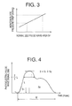
- a cuff pressure regulating means 72 changes a pressing pressure of the cuff 10 according to a well-known blood pressure measuring method during a blood pressure measurement of a blood pressure measuring device 70, which periodically starts a blood pressure measuring operation for calibrating pulse wave area-blood pressure relationship shown in Fig. 3.
- the cuff pressure regulating means 72 increases the cuff pressure to a target value (e.g., 180 mmHg) which is greater than a systolic blood pressure value of the subject, and then slowly decreases it at the rate of about 3 mmHg/sec while a blood pressure measuring algorithm is carried out.
- a target value e.g. 180 mmHg
- the cuff pressure regulating means 72 releases the pressure of the cuff 10.
- the blood pressure measuring device 70 measures a systolic, a mean and a diastolic blood pressure value, BP SYS , BP MEAN , BP DIA , of the patient, according to a well-known oscillometric method, based on a variation of respective magnitudes of heartbeat-synchronous pulses of the pulse-wave signal SM 1 obtained while the cuff pressure is slowly changed, and controls the display device 36 so as to indicate the measured blood pressure values.
- the photoelectric pulse-wave sensor 40 detects a photoelectric pulse wave from the finger of the subject which is accommodated in the housing 42 thereof and outputs the photoelectric pulse wave signal SM 2 representative of the detected photoelectric pulse wave.
- the photoelectric pulse-wave sensor 40 corresponds to the volume pulse-wave sensor.
- a normalized pulse-wave area calculating means 74 successively calculates an area S F which is defined by a waveform of each of heartbeat-synchronous pulses of the photoelectric pulse wave (or signal SM 2 ) and is normalized based on a period and an amplitude of the each pulse of the photoelectric pulse wave. More specifically, as shown in Fig.
- the waveform of each pulse of the photoelectric pulse wave is defined by a series of data points indicative of respective magnitudes of the photoelectric pulse-wave signal SM 2 which are input to the control device 28 at a predetermined interval such as several milliseconds to several tens of milliseconds.
- the normalized pulse-wave area S F is a dimensionless value indicative of a ratio of the pulse-wave area S to an area defined by the period W and the amplitude L of each pulse of the photoelectric pulse wave. In other cases, a symbol %MAP may be used in place of the symbol S F .
- a pulse wave area-blood pressure relationship determining means 76 determines, in advance, a relationship between pulse-wave area and blood pressure, based on a normalized pulse-wave area value S F calculated by the normalized pulse-wave area calculating means 74 and a blood pressure value (one of a systolic, a mean, and a diastolic blood pressure value, BP SYS , BP MEAN , BP DIA ) measured by the blood pressure measuring device 70, when the blood pressure value is measured by the device 70.
- a blood pressure value one of a systolic, a mean, and a diastolic blood pressure value, BP SYS , BP MEAN , BP DIA
- the constants ⁇ , ⁇ in the expression are both determined as values for the specific subject.
- the one or two constants ⁇ , ⁇ in the expression is or are corrected each time a blood pressure measurement is carried out by the blood pressure measuring device 70.
- systolic monitor blood-pressure values are successively determined.
- mean monitor blood-pressure values are successively determined; and in the case where one or more diastolic blood pressure values BP DIA are used to determine the expression, diastolic monitor blood-pressure values are successively determined
- Fig. 5 is a flow chart representing an operation of the electronic control device 28 of the BP monitor apparatus 8.
- the control of the CPU 30 begins with Step SA1 of the flow chart of Fig. 5, where counters and registers (not shown) are reset.
- Step SA1 is followed by Step SA2 to quickly increase the cuff pressure for a blood pressure measurement, by switching the selector valve 16 to the inflation position and operating the air pump 18.
- Step SA2 corresponds to the cuff pressure regulating means 72.
- Step SA3 corresponding to the normalized pulse-wave area calculating means 74.
- Step SA3 is followed by Step SA4 to judge whether or not the cuff pressure P C is equal to or greater than a predetermined target value P CM (e.g., 180 mmHg). If a negative judgment is made at Step SA4, the control of the CPU 30 goes back to Step SA2 so as to continue the increasing of the cuff pressure P C . On the other hand, if a positive judgment is made at Step SA4, the control of the CPU 30 goes to Step SA5 to carry out a blood pressure measuring algorithm. More specifically, the air pump 18 is stopped and the selector valve 16 is switched to the slow-deflation position where the selector valve 16 permits the pressurized air to be slowly discharged from the cuff 10.
- P CM e.g. 180 mmHg
- a systolic blood pressure BP SYS , a mean blood pressure value BP MEAN , and a diastolic blood pressure value BP DIA are determined, according to a well known oscillometric type blood pressure determining algorithm, based on a variation of respective amplitudes of pulses of the pulse wave represented by the pulse-wave signal SM 1 obtained while the cuff pressure is slowly decreased at a predetermined rate of 3 mmHg/sec, and a pulse rate is determined based on an interval of successive two pulses of the pulse wave.
- Step SA5 corresponds to part of the blood pressure measuring device 70.
- Step SA6 corresponds to the pulse wave area-blood pressure relationship determining means 76.
- Step SA6 is followed by Step SA7 to judge whether or not one pulse of the photoelectric pulse wave has been read in. If a negative judgment is made at Step SA7, the control of the CPU 30 waits until a positive judgment is made at Step SA7. If a positive judgment is made at Step SA7, the control of the CPU 30 goes to Step SA8 corresponding to the normalized pulse-wave area calculating means 74. At Step SA8, the CPU 30 calculates a normalized pulse-wave area S F based on the waveform of the one pulse of the photoelectric pulse wave read in at Step SA7 in the same manner as carried out at Step SA3.
- Step SA9 corresponds to the monitor blood pressure determining means 78.
- a predetermined period e.g. 15 to 20 minutes
- the monitor blood-pressure values VRBP are successively determined by the monitor blood pressure determining means 78 (Step SA9), based on the normalized pulse-wave area values S F successively obtained from the respective waveforms of heartbeat-synchronous pulses of the photoelectric pulse wave detected by the photoelectric pulse-wave sensor 40, according to the pulse wave area-blood pressure relationship determined by the pulse wave area-blood pressure relationship determining means 76.
- the BP monitor apparatus 8 can obtain a monitor blood-pressure value from each of heartbeat-synchronous pulses of the signal SM 2 , so that the apparatus need not carry out the blood pressure measurements at an unnecessarily short interval for improving the accuracy of the blood pressure monitor operation.
- the frequency of pressing of the cuff is decreased and the distress of the subject is minimized.
- the photoelectric pulse-wave sensor 40 can be easily worn on the subject. Since the signal SM 2 detected by the sensor 40 is not affected by the body movement of the subject or the like, the BP monitor apparatus 8 can continue the blood pressure monitor operation with accuracy.
- the normalized pulse-wave area S F is obtained by normalizing the pulse-wave area S defined by the waveform of each pulse of the photoelectric pulse wave, based on the period W and the amplitude L of the waveform of the pulse of the photoelectric pulse wave. Accordingly, the normalized pulse-wave area S F is not influenced by the change of the heart rate, body temperature, or the like, of the subject, whereby the BP monitor apparatus 8 can obtain reliable monitor blood-pressure values VRBP.
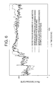
- Fig. 6 shows respective trend graphs of the monitor blood pressure VRBP (systolic blood pressure), a blood pressure SBP (systolic blood pressure) and another monitor blood pressure AMPBP (systolic blood pressure), which are indicated at solid line, one-dot chain line and broken line, respectively.
- the monitor blood-pressure values VRBP are determined or estimated based on the normalized pulse-wave area values S F .
- the blood pressure values SBP are measured by an A-LINE method in which a pressure in a blood vessel of the subject is directly measured by utilizing a catheter.
- The- monitor blood-pressure values AMPBP are determined or estimated based on respective amplitudes AMP of heartbeat-synchronous pulses of the photoelectric pulse wave, according to a predetermined relationship between pulse amplitude and blood pressure.
- Fig. 7 shows a correlation between monitor blood pressure VRBP and blood pressure SBP.
- Fig. 8 shows a correlation between monitor blood pressure AMPBP and blood pressure BP.
- the monitor blood pressure VRBP estimated based on the normalized pulse-wave area S F faithfully follows the blood pressure SBP measured by the A-LINE method, in comparison with the monitor blood pressure AMPBP estimated based on the pulse amplitude AMP. That is, the monitor blood pressure VRBP enjoys a higher correlation with the true blood pressure SBP, than the monitor blood pressure AMPBP, and done not change so largely as time passes. Accordingly, in the BP monitor apparatus 8 which determines the monitor blood pressure VRBP based on the normalized pulse-wave area S F , the need to update the pulse wave area-blood pressure relationship by operating the blood pressure measuring device 70 is minimized.
- Fig. 7 data points indicative of the correlation between the monitor blood pressure VRBP and the blood pressure SBP are more normally distributed on the upper and lower side of the straight line (indicated at solid line) representative of the correlation coefficient, in comparison with those of Fig. 8 which shows the correlation between the monitor blood pressure AMPBP and the blood pressure SBP.
- a blood pressure of the subject can be estimated with high accuracy. That is, the BP monitor apparatus 8 can obtain monitor blood-pressure values VRBP with high reliability.
- the trend graph of the monitor blood-pressure values VRBP successively determined by the monitor blood pressure determining means 78 is indicated on the display device 36, so that a doctor can easily recognize any change of the blood-pressure values and can accurately diagnose the patient.
- Fig. 9 is a block diagram for explaining essential functions of an electronic control device 28 of a BP monitor apparatus to which the second embodiment is applied and which has the same hardware construction as that of the prior embodiment shown in Fig. 1.
- Fig. 10 is a flow chart representing a control program according to which the apparatus of Fig. 9 is operated.
- the electronic control device 28 shown in Fig. 9 is different from the electronic control device 28 shown in Fig. 2 in that the former device 28 additionally includes a monitor-blood-pressure abnormality judging means 80 and Steps SA11 and SA12.
- the reference range is a criterion for judging that the blood pressure of the subject has been abnormally changed. For example, in the case where systolic blood pressure values are determined as the monitor blood-pressure values VRBP, the reference range may be the range of 90 to 180 mmHg.
- the photoelectric pulse-wave sensor 40 is employed, so that the apparatus 8 can monitor the blood pressure of the subject without any delay, based on the monitor blood-pressure value VRBP determined for each of heartbeat-synchronous pulses, whereby the same effects as those of the prior embodiment are obtained.
- the monitor-blood-pressure abnormality judging means 80 Steps SA11 and SA12
- a blood pressure measuring operation of the blood pressure measuring device 70 Step SA5
- the pulse wave area-blood pressure relationship determining means 76 Step SA6.
- the BP monitor apparatus can automatically obtain a blood pressure value with higher reliability upon detection of the blood pressure abnormality, and the reliability of the monitor blood-pressure values obtained after the detection of the abnormality is raised.
- Fig. 11 is a block diagram for explaining essential functions of an electronic control device 28 of a BP monitor apparatus to which the third embodiment is applied and which has the same hardware construction as that of the first embodiment shown in Fig. 1.
- Fig. 12 is a flow chart representing a control program according to which the apparatus of Fig. 11 is operated.
- the electronic control device 28 shown in Fig. 11 is different from the electronic device 28 shown in Fig. 2 in that the former device 28 carries out a blood pressure monitor method different from that carried out by the latter device 28.
- the BP monitor apparatus identifies an abnormal blood-pressure change of the subject, when a change ⁇ D of the normalized pulse-wave area values S F exceeds a reference value ⁇ while the blood pressure measurement using the cuff 10 is not carried out.
- the apparatus starts a blood pressure measuring operation using the cuff 10.
- a blood pressure measuring device 82 starts, at a predetermined period T B , a blood pressure measuring operation using the cuff 10 in the same manner as that in which the BP measuring device 70 does in the prior embodiments, and indicates the measured blood pressure values on the display device 36.
- a pulse-wave area change calculating means 84 calculates a change ⁇ D of the normalized pulse-wave area values S F successively calculated by the normalized pulse-wave area calculating means 74.
- the change ⁇ D may be a rate or amount of change of the current normalized pulse-wave area value S F from a moving average of the normalized pulse-wave area values S F , or the normalized pulse-wave area value S F calculated in the prior blood pressure measurement of the blood pressure measuring device 82.
- a blood-pressure change identifying means 86 identifies an abnormal blood-pressure change of the subject when the change ⁇ D of the normalized pulse-wave area values S F is greater than the reference value ⁇ .
- the blood pressure change identifying means 86 controls the display device 36 to indicate the abnormal blood-pressure change, and controls the pressure measuring device 82 to start a blood pressure measuring operation.
- the blood-pressure change identifying means 86 functions as a blood pressure measurement starting means for starting a blood pressure measuring operation when the change ⁇ D of the normalized pulse-wave area values S F is greater than the reference value ⁇ .
- Step SB1 the CPU 30 carries out an initializing operation in the same manner as carried out at Step SA1.
- Step SB2 is followed by Step SB2 to judge whether or not a photoelectric pulse wave has been detected. If a negative judgment is made at Step SB2, the control of the CPU 30 goes to Step SB3.
- Step SB3 the CPU 30 judges whether or not the predetermined period T B has passed after the prior blood pressure measurement was carried out at Step SB8.
- the period T B may be a relatively long period such as ten and several minutes to several tens of minutes. If a negative judgment is made at Step SB3, the present routine is terminated and the control of the CPU 30 goes back to Step SB1.
- Step SB3 If a positive judgment is made at Step SB3, the control of the CPU goes to Step SB8 to carry out a blood pressure measurement using the cuff 10 according to an oscillometric method, output the measured systolic and diastolic blood pressure values BP SYS , BP DIA , and terminate the present routine.
- Step SB2 If a positive judgment is made at Step SB2, the control of the CPU 30 goes to Step SB4 to read in the photoelectric pulse wave detected by the photoelectric pulse-wave sensor 40.
- Step SB4 is followed by Step SB5 to calculate a normalized pulse-wave area S F in the same manner as carried out at Step SA8.
- Step SB5 corresponds to the pulse-wave area calculating means 74.
- Step SB5 is followed by Step SB6 to calculate a change ⁇ D of the normalized pulse-wave area value S F .
- Step SB6 corresponds to the pulse-wave area change calculating means 84.
- Step SB6 is followed by Step SB7 to judge whether or not the change ⁇ D of the normalized pulse-wave area value S F is equal to or greater than the reference value ⁇ .
- Step SB7 corresponds to the blood-pressure change identifying means 86.
- the reference value ⁇ is experimentally obtained in advance as a criterion for identifying an abnormal blood-pressure change of the subject.
- Step SB7 If a negative judgment is made at Step SB7, the control of the CPU 30 goes to Step SB3. If a positive judgment is made at Step SB7, the control of the CPU 30 goes to Step SB8.
- Step SB8 the CPU 30 starts a blood pressure measuring operation and controls the display device 36 to indicate the abnormal blood-pressure change in characters or symbols together with the measured blood pressure value.
- the normalized pulse-wave area value S F is calculated by the normalized pulse-wave area calculating meals 74 (Step SB5).
- a change ⁇ D of the normalized pulse-wave area values S F is calculated by the pulse-wave area change calculating means 84 (Step SB6).
- the abnormal blood-pressure change of the subject is identified by the blood-pressure change identifying means 86 (Step SB7), when the change ⁇ D of the normalized pulse-wave area value S F is greater than the reference value ⁇ .
- the BP monitor apparatus can identify the abnormal blood-pressure change of the subject based on the change of the normalized pulse-wave area value S F calculated for each pulse of the photoelectric pulse wave.
- the present apparatus need not carry out the blood pressure measurements at an unnecessarily short interval for improving the accuracy of the blood pressure monitor operation, whereby the frequency of pressing of the cuff 10 is decreased and the distress of the subject is minimized.
- the photoelectric pulse-wave sensor 40 can be easily worn on the body portion of the subject. Since the signal detected by the sensor 40 is not changed by the body movement of the subject or the like, the BP monitor apparatus can continue the blood pressure monitor operation with accuracy.
- the blood-pressure change identifying means 86 controls the blood pressure measuring device 82 to start a blood pressure measuring operation upon identification of the abnormal blood-pressure change of the subject.
- the blood pressure measurement of the blood pressure measuring device 82 is carried out, so that the BP monitor apparatus can automatically obtain a blood pressure value with high reliability.
- Fig. 13 shows a BP monitor apparatus which employs a photoelectric pulse wave detecting probe 90 (hereinafter, referred to as the "probe") as part of a pulse oximeter 88 for measuring an oxygen saturation in blood of a living subject.
- the probe 90 functions as the volume pulse-wave sensor.
- the probe 90 is adapted to be set on a body surface 38 of the subject, e.g., a forehead of a patient, with the help of a band (not shown) such that the probe 90 closely contacts the body surface 38.
- the probe 90 includes a container-like housing 92 which opens in a certain direction, a first and a second group of light emitting elements 94a, 94b, such as LEDs (light emitting diodes), which are disposed on an outer peripheral portion of an inner bottom surface of the housing 92 (hereinafter, referred to as the light emitting elements 94 in the case where the first and second groups of light emitting elements 94a, 94b need not be discriminated from each other), a light receiving element 96, such as a photodiode or a phototransister, which is disposed on a central portion of the inner bottom surface of the housing 92, a transparent resin 98 which is integrally disposed in the housing 92 to cover the light emitting elements 94 and the light receiving element 96, and an annular shade member 100 which is disposed between the light emitting elements 94 and the light receiving element 96, for preventing the lights emitted toward the body surface 38 by the light emitting elements 94 and reflected from the body surface 38, from
- the first and second groups of light emitting elements 94a, 94b emit a red light having about 660nm wavelength and an infrared light having about 800 nm wavelength, respectively.
- the first and second light emitting elements 94a, 94b alternately emit the red and infrared lights at a predetermined frequency, according to a drive current supplied from a drive circuit 101.
- the lights emitted toward the body surface 38 by the light emitting elements 94 are reflected from a body tissue of the subject where a dense capillaries occur, and the reflected lights are received by the common light receiving element 96.
- the light receiving element 96 outputs, through a low-pass filter 102, a photoelectric pulse-wave signal SM 3 representative of an amount of the received light.
- the light receiving element 96 is connected to the low-pass filter 102 via an amplifier or the like.
- the low-pass filter 102 eliminates, from the photoelectric pulse-wave signal SM 3 input thereto, noise having frequencies higher than that of a pulse wave, and outputs the noise-free signal SM 3 , to a demultiplexer 104.
- the demultiplexer 104 is alternately switched according to signals supplied thereto from the electronic control device 28 in synchronism with the light emissions of the first and second light emitting element 94a, 94b.
- the demultiplexer 104 successively supplies, to an I/O port (not shown) of an electronic control device 112 of the pulse oximeter 88, an electric signal SM R representative of the red light through a sample-and-hold circuit 106 and an A/D converter 109, and an electric signal SM IR representative of the infrared light through a sample-and-hold circuit 108 and an A/D converter 110.
- the two sample-and-hold circuits 106, 108 hold the electric signals SM R , SM IR input thereto, respectively, and do not output those current signals to the A/D converters 109, 110, before the prior signals SM R , SM IR are completely converted by the A/D converters 109, 110, respectively.
- the electronic control device 112 is connected to a display device (not shown) so as to display the measured blood oxygen saturation.
- the electronic control device 112 is provided by a microcomputer including a central processing unit (CPU) 114, a random access memory (RAM) 116 and a read only memory (ROM) 118.
- the electronic control device 112 mutually communicate information with the electronic control device 28.
- the CPU 114 performs a blood oxygen saturation measurement, by utilizing the temporary storage function of the RAM 116 according to the programs pre-stored in the ROM 118, calculates an oxygen saturation based on the electric signals SM R , SM IR , controls the display device to indicate the measured oxygen saturation, and outputs, as the volume pulse wave, the electric signal SM R or SM IR representative of a waveform similar to that shown in Fig. 4 to the electronic control device 28.
- the blood oxygen saturation is determined based on an actual ratio ⁇ (V dR - V SR )/(V dR + V SR ) ⁇ / ⁇ (V dIR - V SIR )/(V dIR + V SIR ) ⁇ , according to a predetermined relationship between ratio ⁇ (V dR - V SR )/(V dR + V SR ) ⁇ / ⁇ (V dIR - V SIR )/(V dIR + V SIR ) ⁇ and blood oxygen saturation.
- the blood oxygen saturation determining method is disclosed in U.S. Patent No. 5,131,391.
- the values V dR , V SR respectively represent an upper and a lower peak value of a waveform of one pulse of the photoelectric pulse wave obtained from the red light
- the values V dIR , V SIR respectively represent an upper and a lower peak value of a waveform of one pulse of the photoelectric pulse wave obtained from the infrared light.
- V dR - V SR , V dIR - V SIR respectively represent amplitudes of alternating current components of the respective photoelectric pulse waves obtained from the red and the infrared lights.
- the values, V dR + V SR , V dIR + V SIR' respectively represent double the respective amplitudes of direct current components of the respective photoelectric pulse waves obtained from the red and the infrared lights.
- the photoelectric pulse-wave sensor 40 or the blood oxygen saturation detecting probe 90 which output the electric signals SM R , SM IR are employed as the volume pulse-wave sensor
- an impedance pulse-wave sensor which outputs an impedance pulse-wave signal may be employed.
- the impedance pulse-wave sensor includes at least two electrodes being set on different locations of a skin of a living subject at a predetermined interval, and outputs the impedance pulse-wave signal representing an instantaneous blood volume in a tissue of the skin located between the two electrodes.
- a blood pressure of a living subject is monitored based on a normalized pulse-wave area value S F successively calculated for each pulse of the photoelectric pulse wave.
- the blood pressure of the subject may be monitored, based on a normalized pulse-wave area value S F calculated every second pulse of the photoelectric pulse wave, or at an interval such as several seconds to several tens of seconds.
- a blood pressure of a living subject is monitored based on a normalized pulse-wave area value S F .
- the normalized pulse-wave area value S F is calculated by normalizing a first pulse-wave area S 1 defined by the waveform of a pulse of the photoelectric pulse wave between a rising point and an upper peak point of the waveform shown in Fig. 4.
- the normalized second pulse-wave area is calculated by normalizing a second pulse-wave area S 2 which corresponds to the rest that the first pulse-wave area S 1 is taken away from the pulse-wave area S.
- a normalized value I/W which is obtained by normalizing a width I between two points on the waveform which correspond to L ⁇ (2/3) may be employed.
- the BP monitor apparatus may calculate a value relating to an area defined by a waveform of each of heartbeat-synchronous pulses of the volume pulse wave, or a value representative of a sharpness of an upper peak of the waveform of each pulse of the volume pulse wave.
- a quadratic or higher polynomial expression may be employed, and one or more correcting terms may be added if necessary.
- the blood pressure measuring devices 70, 82 measure a blood pressure value of a living subject based on a variation of the pulse wave produced while the cuff pressure P C is slowly decreased.
- the blood pressure measuring devices may measure a blood pressure value of the subject based on a variation of a pulse wave produced while the cuff pressure P C is slowly increased.
- the blood pressure measuring devices 70, 82 employ the so-called oscillometric method to measure a blood pressure value of a living subject based on a variation of a pressure pulse wave produced while the cuff pressure P C is changed.
- the blood pressure measuring devices may employ a so-called Korotokoff-sound method to determine a blood pressure value of the subject based on the pressing pressure of the cuff 10 at the time of occurrence or disappearance of Korotokoff-sounds.
Landscapes
- Health & Medical Sciences (AREA)
- Life Sciences & Earth Sciences (AREA)
- Vascular Medicine (AREA)
- Cardiology (AREA)
- Biomedical Technology (AREA)
- Heart & Thoracic Surgery (AREA)
- Physiology (AREA)
- Biophysics (AREA)
- Pathology (AREA)
- Engineering & Computer Science (AREA)
- Ophthalmology & Optometry (AREA)
- Physics & Mathematics (AREA)
- Medical Informatics (AREA)
- Molecular Biology (AREA)
- Surgery (AREA)
- Animal Behavior & Ethology (AREA)
- General Health & Medical Sciences (AREA)
- Public Health (AREA)
- Veterinary Medicine (AREA)
- Measuring Pulse, Heart Rate, Blood Pressure Or Blood Flow (AREA)
Description
Claims (7)
- A blood pressure monitor apparatus comprising:a blood pressure measuring device (10, 14, 22, 24, 70, 72, SA5) which includes a cuff (10) adapted to be pressed on an artery of a living subject and measures a blood pressure value of the subject by changing a pressing pressure of the cuff; anda volume pulse wave detecting device (40) which detects a volume pulse wave of the subject, the blood pressure monitor apparatus being characterised by further comprising:normalised pulse-wave area calculating means (74, SA3, SA8) for successively calculating an area which is defined by a waveform of each of heartbeat-synchronous pulses of the volume pulse wave detected by said volume pulse wave detecting device and is normalised based on a period (W) and an amplitude (L) of said each pulse of the volume pulse wave;pulse wave area-blood pressure relationship determining means (76, SA6) for determining a relationship between pulse-wave area and blood pressure, based on a normalised pulse-wave area value calculated by said normalised pulse-wave area calculating means and a blood pressure value measured by said blood pressure measuring device, when said blood pressure value is measured; andmonitor blood pressure determining means (78, SA9) for successively determining a monitor-blood-pressure value of the subject, based on each of normalised pulse-wave area values successively calculated by said normalised pulse-wave area calculating means, according to the pulse wave area-blood pressure relationship determined by said pulse wave area-blood pressure relationship determining means.
- The blood pressure monitor apparatus according to claim 1, further comprising monitor-blood-pressure abnormality judging means (80, SA11) for judging whether each of the monitor-blood-pressure values successively determined by said monitor blood pressure determining means does not fall in a reference range, and controlling, when a negative judgment is made, said blood pressure measuring device to start a blood pressure measuring operation.
- The blood pressure monitor apparatus according to claim 1 or claim 2, further comprising an indicating device (36, SA9) which indicates a trend graph of the monitor-blood-pressure values successively determined by said monitor blood pressure determining means.
- The blood pressure monitor apparatus according to claim 3, wherein said indicating device comprises means (SA12) for indicating that said negative judgment is made by said monitor-blood-pressure abnormality judging means.
- The blood pressure monitor apparatus according to anyone of claims 1-4, wherein said volume pulse wave detecting device comprises a photoelectric pulse-wave sensor (90) including a light-emitting and a light-receiving element, the light-emitting element emitting, toward a skin of the subject, a light having a wavelength which can be reflected by hemoglobin present in blood of the skin, the light-receiving element receiving the light scattered by the hemoglobin from the skin, said photoelectric pulse-wave sensor outputting a photoelectric pulse wave signal representing an instantaneous blood volume in capillaries of the skin.
- The blood pressure monitor apparatus according to anyone of claims 1-4, wherein said volume pulse wave detecting device comprises an impedance pulse-wave sensor including at least two electrodes being set on different locations of the skin of the subject at a predetermined interval, said impedance pulse-wave sensor outputting an impedance pulse-wave signal representing an instantaneous blood volume in a tissue of the skin located between said two electrodes.
- The blood pressure monitor apparatus according to claim 1, wherein said normalised pulse-wave area calculating means calculates a normalised pulse-wave area value SF according to the following expression:
Priority Applications (1)
| Application Number | Priority Date | Filing Date | Title |
|---|---|---|---|
| EP01130723A EP1195132B1 (en) | 1996-05-02 | 1997-04-30 | Blood pressure monitor apparatus |
Applications Claiming Priority (3)
| Application Number | Priority Date | Filing Date | Title |
|---|---|---|---|
| JP11159096 | 1996-05-02 | ||
| JP111590/96 | 1996-05-02 | ||
| JP11159096A JP3666987B2 (en) | 1996-05-02 | 1996-05-02 | Blood pressure monitoring device |
Related Child Applications (1)
| Application Number | Title | Priority Date | Filing Date |
|---|---|---|---|
| EP01130723.8 Division-Into | 2001-12-21 |
Publications (2)
| Publication Number | Publication Date |
|---|---|
| EP0804899A1 EP0804899A1 (en) | 1997-11-05 |
| EP0804899B1 true EP0804899B1 (en) | 2002-09-11 |
Family
ID=14565230
Family Applications (2)
| Application Number | Title | Priority Date | Filing Date |
|---|---|---|---|
| EP97107236A Expired - Lifetime EP0804899B1 (en) | 1996-05-02 | 1997-04-30 | Blood pressure monitor apparatus |
| EP01130723A Expired - Lifetime EP1195132B1 (en) | 1996-05-02 | 1997-04-30 | Blood pressure monitor apparatus |
Family Applications After (1)
| Application Number | Title | Priority Date | Filing Date |
|---|---|---|---|
| EP01130723A Expired - Lifetime EP1195132B1 (en) | 1996-05-02 | 1997-04-30 | Blood pressure monitor apparatus |
Country Status (5)
| Country | Link |
|---|---|
| US (1) | US5776071A (en) |
| EP (2) | EP0804899B1 (en) |
| JP (1) | JP3666987B2 (en) |
| DE (2) | DE69723743D1 (en) |
| ES (1) | ES2183040T3 (en) |
Families Citing this family (89)
| Publication number | Priority date | Publication date | Assignee | Title |
|---|---|---|---|---|
| JP3666987B2 (en) * | 1996-05-02 | 2005-06-29 | コーリンメディカルテクノロジー株式会社 | Blood pressure monitoring device |
| JP3208066B2 (en) * | 1996-08-01 | 2001-09-10 | 日本コーリン株式会社 | Blood pressure monitoring device |
| JP3412439B2 (en) * | 1997-03-12 | 2003-06-03 | ミノルタ株式会社 | Non-magnetic one-component negatively charged color developer |
| JP3330079B2 (en) * | 1998-05-12 | 2002-09-30 | 日本コーリン株式会社 | Non-invasive continuous blood pressure estimation device |
| JP3213278B2 (en) * | 1998-05-12 | 2001-10-02 | 日本コーリン株式会社 | Non-invasive continuous blood pressure estimation device |
| US6036652A (en) * | 1998-05-12 | 2000-03-14 | Colin Corporation | Blood pressure estimating apparatus and method |
| JP3840816B2 (en) * | 1998-10-02 | 2006-11-01 | オムロンヘルスケア株式会社 | Blood pressure monitoring device |
| JP2000107146A (en) * | 1998-10-07 | 2000-04-18 | Nippon Colin Co Ltd | Blood pressure monitoring device |
| JP2000126142A (en) * | 1998-10-29 | 2000-05-09 | Nippon Colin Co Ltd | Non-regard blood continuous blood pressure estimating device |
| JP2000135202A (en) * | 1998-10-30 | 2000-05-16 | Nippon Colin Co Ltd | Blood pressure moitoring device |
| JP2000157499A (en) | 1998-11-27 | 2000-06-13 | Nippon Colin Co Ltd | Blood pressure monitoring device |
| US6120459A (en) * | 1999-06-09 | 2000-09-19 | Nitzan; Meir | Method and device for arterial blood pressure measurement |
| US9248306B2 (en) | 1999-09-30 | 2016-02-02 | Physio-Control, Inc. | Pulse detection apparatus, software, and methods using patient physiological signals |
| US20040039419A1 (en) * | 1999-09-30 | 2004-02-26 | Stickney Ronald E. | Apparatus, software, and methods for cardiac pulse detection using a piezoelectric sensor |
| US20030109790A1 (en) * | 2001-12-06 | 2003-06-12 | Medtronic Physio-Control Manufacturing Corp. | Pulse detection method and apparatus using patient impedance |
| US6440082B1 (en) | 1999-09-30 | 2002-08-27 | Medtronic Physio-Control Manufacturing Corp. | Method and apparatus for using heart sounds to determine the presence of a pulse |
| GB2356252B (en) * | 1999-11-12 | 2004-02-25 | Micro Medical Ltd | Apparatus for measuring the shape of an arterial pressure pulse in a person |
| US6519490B1 (en) * | 1999-12-20 | 2003-02-11 | Joseph Wiesel | Method of and apparatus for detecting arrhythmia and fibrillation |
| AU2001221391A1 (en) | 2000-01-26 | 2001-08-07 | Vsm Medtech Ltd. | Continuous blood pressure monitoring method and apparatus |
| DE60037718D1 (en) * | 2000-02-21 | 2008-02-21 | Critikon Co | Automatic blood pressure monitoring |
| JP2001286521A (en) * | 2000-04-10 | 2001-10-16 | Nippon Colin Co Ltd | Vein thrombus embolism preventing device |
| JP3429487B2 (en) * | 2000-10-30 | 2003-07-22 | 日本コーリン株式会社 | Atherosclerosis evaluation device |
| JP2002172095A (en) * | 2000-12-06 | 2002-06-18 | K & S:Kk | Pulse measurement device |
| WO2003001180A2 (en) | 2001-06-20 | 2003-01-03 | Purdue Research Foundation | Body-member-illuminating pressure cuff for noninvasive optical measurement |
| US6893401B2 (en) * | 2001-07-27 | 2005-05-17 | Vsm Medtech Ltd. | Continuous non-invasive blood pressure monitoring method and apparatus |
| US6953435B2 (en) | 2001-12-10 | 2005-10-11 | Kabushiki Gaisha K -And- S | Biological data observation apparatus |
| JP3706841B2 (en) * | 2002-04-16 | 2005-10-19 | 株式会社ケーアンドエス | Biological data measuring device |
| WO2003071938A1 (en) * | 2002-02-22 | 2003-09-04 | Datex-Ohmeda, Inc. | Monitoring physiological parameters based on variations in a photoplethysmographic signal |
| US6709402B2 (en) | 2002-02-22 | 2004-03-23 | Datex-Ohmeda, Inc. | Apparatus and method for monitoring respiration with a pulse oximeter |
| US6896661B2 (en) * | 2002-02-22 | 2005-05-24 | Datex-Ohmeda, Inc. | Monitoring physiological parameters based on variations in a photoplethysmographic baseline signal |
| US6702752B2 (en) | 2002-02-22 | 2004-03-09 | Datex-Ohmeda, Inc. | Monitoring respiration based on plethysmographic heart rate signal |
| US6805673B2 (en) | 2002-02-22 | 2004-10-19 | Datex-Ohmeda, Inc. | Monitoring mayer wave effects based on a photoplethysmographic signal |
| JP2003250772A (en) * | 2002-03-01 | 2003-09-09 | Nippon Colin Co Ltd | Device for determining normal pulse wave velocity information and device for measuring pulse wave velocity information |
| US20040039420A1 (en) * | 2002-08-26 | 2004-02-26 | Medtronic Physio-Control Manufacturing Corp. | Apparatus, software, and methods for cardiac pulse detection using accelerometer data |
| US20040116969A1 (en) | 2002-08-26 | 2004-06-17 | Owen James M. | Pulse detection using patient physiological signals |
| US7810359B2 (en) | 2002-10-01 | 2010-10-12 | Nellcor Puritan Bennett Llc | Headband with tension indicator |
| US7698909B2 (en) | 2002-10-01 | 2010-04-20 | Nellcor Puritan Bennett Llc | Headband with tension indicator |
| US7569018B1 (en) | 2003-02-18 | 2009-08-04 | Purdue Research Foundation | Apparatus and method for noninvasively detecting the quality of cardiac pumping |
| US7047056B2 (en) | 2003-06-25 | 2006-05-16 | Nellcor Puritan Bennett Incorporated | Hat-based oximeter sensor |
| US7455643B1 (en) * | 2003-07-07 | 2008-11-25 | Nellcor Puritan Bennett Ireland | Continuous non-invasive blood pressure measurement apparatus and methods providing automatic recalibration |
| US8412297B2 (en) | 2003-10-01 | 2013-04-02 | Covidien Lp | Forehead sensor placement |
| US7164938B2 (en) * | 2004-06-21 | 2007-01-16 | Purdue Research Foundation | Optical noninvasive vital sign monitor |
| US8116839B1 (en) | 2005-02-25 | 2012-02-14 | General Electric Company | System for detecting potential probe malfunction conditions in a pulse oximeter |
| US7403806B2 (en) | 2005-06-28 | 2008-07-22 | General Electric Company | System for prefiltering a plethysmographic signal |
| CN100496388C (en) * | 2005-08-31 | 2009-06-10 | 深圳迈瑞生物医疗电子股份有限公司 | Device for calculating blood pressure by using signal transformation |
| WO2007046283A1 (en) * | 2005-10-18 | 2007-04-26 | Sharp Kabushiki Kaisha | Bioinformation acquiring device and bioinformation acquiring method |
| EP2139387A4 (en) * | 2007-03-28 | 2013-11-06 | Kaz Inc | Arterial blood pressure monitor with a liquid filled cuff |
| JP4971041B2 (en) * | 2007-06-11 | 2012-07-11 | 株式会社デンソー | Blood pressure measuring device, program, and recording medium |
| US8660799B2 (en) | 2008-06-30 | 2014-02-25 | Nellcor Puritan Bennett Ireland | Processing and detecting baseline changes in signals |
| US20090326386A1 (en) * | 2008-06-30 | 2009-12-31 | Nellcor Puritan Bennett Ireland | Systems and Methods for Non-Invasive Blood Pressure Monitoring |
| US8398556B2 (en) | 2008-06-30 | 2013-03-19 | Covidien Lp | Systems and methods for non-invasive continuous blood pressure determination |
| US8506498B2 (en) | 2008-07-15 | 2013-08-13 | Nellcor Puritan Bennett Ireland | Systems and methods using induced perturbation to determine physiological parameters |
| US8257274B2 (en) | 2008-09-25 | 2012-09-04 | Nellcor Puritan Bennett Llc | Medical sensor and technique for using the same |
| US8364220B2 (en) | 2008-09-25 | 2013-01-29 | Covidien Lp | Medical sensor and technique for using the same |
| US9314168B2 (en) * | 2008-09-30 | 2016-04-19 | Nellcor Puritan Bennett Ireland | Detecting sleep events using localized blood pressure changes |
| US9687161B2 (en) | 2008-09-30 | 2017-06-27 | Nellcor Puritan Bennett Ireland | Systems and methods for maintaining blood pressure monitor calibration |
| US8532751B2 (en) | 2008-09-30 | 2013-09-10 | Covidien Lp | Laser self-mixing sensors for biological sensing |
| US9301697B2 (en) | 2008-09-30 | 2016-04-05 | Nellcor Puritan Bennett Ireland | Systems and methods for recalibrating a non-invasive blood pressure monitor |
| US9078609B2 (en) * | 2008-10-02 | 2015-07-14 | Nellcor Puritan Bennett Ireland | Extraction of physiological measurements from a photoplethysmograph (PPG) signal |
| US8216136B2 (en) | 2009-03-05 | 2012-07-10 | Nellcor Puritan Bennett Llc | Systems and methods for monitoring heart rate and blood pressure correlation |
| US8515515B2 (en) | 2009-03-25 | 2013-08-20 | Covidien Lp | Medical sensor with compressible light barrier and technique for using the same |
| US8781548B2 (en) | 2009-03-31 | 2014-07-15 | Covidien Lp | Medical sensor with flexible components and technique for using the same |
| US9198582B2 (en) | 2009-06-30 | 2015-12-01 | Nellcor Puritan Bennett Ireland | Determining a characteristic physiological parameter |
| US8290730B2 (en) | 2009-06-30 | 2012-10-16 | Nellcor Puritan Bennett Ireland | Systems and methods for assessing measurements in physiological monitoring devices |
| US20110021929A1 (en) * | 2009-07-27 | 2011-01-27 | Nellcor Puritan Bennett Ireland | Systems and methods for continuous non-invasive blood pressure monitoring |
| US8628477B2 (en) | 2009-07-31 | 2014-01-14 | Nellcor Puritan Bennett Ireland | Systems and methods for non-invasive determination of blood pressure |
| US9220440B2 (en) * | 2009-09-21 | 2015-12-29 | Nellcor Puritan Bennett Ireland | Determining a characteristic respiration rate |
| US9066660B2 (en) | 2009-09-29 | 2015-06-30 | Nellcor Puritan Bennett Ireland | Systems and methods for high-pass filtering a photoplethysmograph signal |
| US8463347B2 (en) * | 2009-09-30 | 2013-06-11 | Nellcor Puritan Bennett Ireland | Systems and methods for normalizing a plethysmograph signal for improved feature analysis |
| US9451887B2 (en) | 2010-03-31 | 2016-09-27 | Nellcor Puritan Bennett Ireland | Systems and methods for measuring electromechanical delay of the heart |
| US8898037B2 (en) | 2010-04-28 | 2014-11-25 | Nellcor Puritan Bennett Ireland | Systems and methods for signal monitoring using Lissajous figures |
| JP2011234876A (en) * | 2010-05-10 | 2011-11-24 | K & S:Kk | Blood pressure measuring instrument |
| US9408542B1 (en) | 2010-07-22 | 2016-08-09 | Masimo Corporation | Non-invasive blood pressure measurement system |
| US8825428B2 (en) | 2010-11-30 | 2014-09-02 | Neilcor Puritan Bennett Ireland | Methods and systems for recalibrating a blood pressure monitor with memory |
| US9357934B2 (en) | 2010-12-01 | 2016-06-07 | Nellcor Puritan Bennett Ireland | Systems and methods for physiological event marking |
| US9259160B2 (en) | 2010-12-01 | 2016-02-16 | Nellcor Puritan Bennett Ireland | Systems and methods for determining when to measure a physiological parameter |
| US9060695B2 (en) | 2011-11-30 | 2015-06-23 | Covidien Lp | Systems and methods for determining differential pulse transit time from the phase difference of two analog plethysmographs |
| JP5844187B2 (en) | 2012-03-23 | 2016-01-13 | 富士フイルム株式会社 | Image analysis apparatus and method, and program |
| US8951204B2 (en) * | 2012-05-04 | 2015-02-10 | The Guy P. Curtis And Frances L. Curtis Trust | Method for using a pulse oximetry signal to monitor blood pressure |
| EP2869764B1 (en) | 2012-07-06 | 2023-07-26 | Orsense Ltd. | System and method for measuring blood parameters |
| EP2992820B1 (en) * | 2014-08-11 | 2023-05-10 | Tata Consultancy Services Limited | Measuring blood pressure |
| JP5997865B1 (en) * | 2014-10-20 | 2016-09-28 | 浜松ホトニクス株式会社 | Blood pressure measurement method, blood pressure measurement device, blood pressure measurement program, and recording medium for recording the program |
| US11172891B2 (en) | 2015-02-09 | 2021-11-16 | Nitto Denko Corporation | Method and apparatus for deriving mean arterial pressure of a subject |
| WO2017117375A1 (en) * | 2015-12-29 | 2017-07-06 | Lifeq Global Limited | Non-invasive measurement of ambulatory blood pressure |
| JP6176693B1 (en) * | 2016-11-07 | 2017-08-09 | 株式会社ケーアンドエス | Blood pressure measurement device |
| JP2021052811A (en) * | 2017-12-26 | 2021-04-08 | 株式会社タニタ | Blood pressure measuring device |
| KR20200040563A (en) * | 2018-10-10 | 2020-04-20 | 삼성전자주식회사 | Apparatus and method for estimating blood pressure |
| US11167145B2 (en) | 2019-10-30 | 2021-11-09 | Guy P. Curtis And Frances L. Curtis Trust | System and method for indirect measurement of ventricular contractility |
| US20230293117A1 (en) * | 2022-03-17 | 2023-09-21 | Microlife Corporation | Method for estimating blood pressures using photoplethysmography signal analysis and system using the same |
Family Cites Families (22)
| Publication number | Priority date | Publication date | Assignee | Title |
|---|---|---|---|---|
| CH557671A (en) * | 1973-09-03 | 1975-01-15 | Pestalozzi Andreas | Continuous indirect blood pressure measuring system - uses peripheral blood flow calibrated intermittently by indirect pressure measurement |
| JPS59197238A (en) * | 1983-04-25 | 1984-11-08 | 株式会社日本コ−リン | Automatic hemomanometer apparatus |
| US4669485A (en) * | 1984-02-17 | 1987-06-02 | Cortronic Corporation | Apparatus and method for continuous non-invasive cardiovascular monitoring |
| JP2664918B2 (en) * | 1988-02-23 | 1997-10-22 | コーリン電子株式会社 | Blood pressure monitoring device |
| US4889133A (en) * | 1988-05-25 | 1989-12-26 | Protocol Systems, Inc. | Method for noninvasive blood-pressure measurement by evaluation of waveform-specific area data |
| JP2688512B2 (en) * | 1988-12-28 | 1997-12-10 | コーリン電子株式会社 | Blood pressure monitoring device |
| JP2745467B2 (en) * | 1989-05-29 | 1998-04-28 | オムロン株式会社 | Electronic sphygmomanometer |
| JP2766317B2 (en) * | 1989-06-22 | 1998-06-18 | コーリン電子株式会社 | Pulse oximeter |
| US5140990A (en) * | 1990-09-06 | 1992-08-25 | Spacelabs, Inc. | Method of measuring blood pressure with a photoplethysmograph |
| US5269310A (en) * | 1990-09-06 | 1993-12-14 | Spacelabs Medical, Inc. | Method of measuring blood pressure with a plethysmograph |
| US5241964A (en) * | 1990-10-31 | 1993-09-07 | Medwave, Incorporated | Noninvasive, non-occlusive method and apparatus which provides a continuous indication of arterial pressure and a beat-by-beat characterization of the arterial system |
| JPH04367648A (en) * | 1991-06-14 | 1992-12-18 | Colleen Denshi Kk | Blood pressure monitor device |
| JP3188535B2 (en) * | 1992-11-04 | 2001-07-16 | ウエダアヴァンセ株式会社 | Blood pressure measurement device |
| US5533511A (en) * | 1994-01-05 | 1996-07-09 | Vital Insite, Incorporated | Apparatus and method for noninvasive blood pressure measurement |
| US5497779A (en) * | 1994-03-08 | 1996-03-12 | Colin Corporation | Pulse wave detecting apparatus |
| US5590649A (en) * | 1994-04-15 | 1997-01-07 | Vital Insite, Inc. | Apparatus and method for measuring an induced perturbation to determine blood pressure |
| JP3445655B2 (en) * | 1994-05-12 | 2003-09-08 | 日本コーリン株式会社 | Blood pressure monitoring device |
| JP3318727B2 (en) * | 1994-06-06 | 2002-08-26 | 日本光電工業株式会社 | Pulse wave transit time sphygmomanometer |
| JP3602875B2 (en) * | 1994-10-11 | 2004-12-15 | コーリンメディカルテクノロジー株式会社 | Blood pressure monitoring device |
| DE69532610T2 (en) * | 1994-10-13 | 2004-08-05 | Masimo Corp., Irvine | AUTOMATICALLY ACTIVATED BLOOD PRESSURE MEASURING DEVICE |
| JP3599819B2 (en) * | 1995-03-27 | 2004-12-08 | コーリンメディカルテクノロジー株式会社 | Biological information monitoring device |
| JP3666987B2 (en) * | 1996-05-02 | 2005-06-29 | コーリンメディカルテクノロジー株式会社 | Blood pressure monitoring device |
-
1996
- 1996-05-02 JP JP11159096A patent/JP3666987B2/en not_active Expired - Fee Related
-
1997
- 1997-04-25 US US08/845,478 patent/US5776071A/en not_active Expired - Lifetime
- 1997-04-30 DE DE69723743T patent/DE69723743D1/en not_active Expired - Lifetime
- 1997-04-30 EP EP97107236A patent/EP0804899B1/en not_active Expired - Lifetime
- 1997-04-30 EP EP01130723A patent/EP1195132B1/en not_active Expired - Lifetime
- 1997-04-30 DE DE69715290T patent/DE69715290T2/en not_active Expired - Fee Related
- 1997-04-30 ES ES97107236T patent/ES2183040T3/en not_active Expired - Lifetime
Also Published As
| Publication number | Publication date |
|---|---|
| ES2183040T3 (en) | 2003-03-16 |
| DE69715290D1 (en) | 2002-10-17 |
| JP3666987B2 (en) | 2005-06-29 |
| DE69723743D1 (en) | 2003-08-28 |
| US5776071A (en) | 1998-07-07 |
| JPH09294728A (en) | 1997-11-18 |
| EP1195132A1 (en) | 2002-04-10 |
| EP1195132B1 (en) | 2003-07-23 |
| DE69715290T2 (en) | 2003-07-31 |
| EP0804899A1 (en) | 1997-11-05 |
Similar Documents
| Publication | Publication Date | Title |
|---|---|---|
| EP0804899B1 (en) | Blood pressure monitor apparatus | |
| US6022320A (en) | Blood pressure monitor apparatus | |
| EP0993803B1 (en) | Blood-pressure monitoring apparatus | |
| US5752920A (en) | Blood pressure monitor apparatus | |
| US5743857A (en) | Blood pressure monitor apparatus | |
| EP0990418B1 (en) | Blood-pressure monitoring apparatus | |
| US6027453A (en) | Blood pressure monitoring apparatus and method | |
| US6827688B2 (en) | Blood pressure monitor | |
| US6645155B2 (en) | Blood pressure monitor apparatus | |
| US6027455A (en) | Blood pressure estimating apparatus and method | |
| US6036651A (en) | Blood pressure estimating apparatus and method | |
| US6251081B1 (en) | Blood-pressure monitoring apparatus | |
| US6527725B1 (en) | Blood pressure estimating apparatus | |
| US6036652A (en) | Blood pressure estimating apparatus and method | |
| EP1157658A1 (en) | Blood pressure monitor apparatus | |
| EP1356764A2 (en) | Living subject monitoring apparatus | |
| US6482163B2 (en) | Postoperative-condition evaluating apparatus | |
| US6500127B1 (en) | Blood pressure monitor apparatus | |
| JP3911843B2 (en) | Blood pressure monitoring device | |
| JPH11299750A (en) | Blood pressure monitor device |
Legal Events
| Date | Code | Title | Description |
|---|---|---|---|
| PUAI | Public reference made under article 153(3) epc to a published international application that has entered the european phase |
Free format text: ORIGINAL CODE: 0009012 |
|
| AK | Designated contracting states |
Kind code of ref document: A1 Designated state(s): DE ES FR GB |
|
| 17P | Request for examination filed |
Effective date: 19971216 |
|
| 17Q | First examination report despatched |
Effective date: 19990326 |
|
| GRAG | Despatch of communication of intention to grant |
Free format text: ORIGINAL CODE: EPIDOS AGRA |
|
| GRAG | Despatch of communication of intention to grant |
Free format text: ORIGINAL CODE: EPIDOS AGRA |
|
| GRAH | Despatch of communication of intention to grant a patent |
Free format text: ORIGINAL CODE: EPIDOS IGRA |
|
| GRAH | Despatch of communication of intention to grant a patent |
Free format text: ORIGINAL CODE: EPIDOS IGRA |
|
| GRAA | (expected) grant |
Free format text: ORIGINAL CODE: 0009210 |
|
| AK | Designated contracting states |
Kind code of ref document: B1 Designated state(s): DE ES FR GB |
|
| REG | Reference to a national code |
Ref country code: GB Ref legal event code: FG4D |
|
| REF | Corresponds to: |
Ref document number: 69715290 Country of ref document: DE Date of ref document: 20021017 |
|
| ET | Fr: translation filed | ||
| REG | Reference to a national code |
Ref country code: ES Ref legal event code: FG2A Ref document number: 2183040 Country of ref document: ES Kind code of ref document: T3 |
|
| PGFP | Annual fee paid to national office [announced via postgrant information from national office to epo] |
Ref country code: ES Payment date: 20030428 Year of fee payment: 7 |
|
| PGFP | Annual fee paid to national office [announced via postgrant information from national office to epo] |
Ref country code: FR Payment date: 20030429 Year of fee payment: 7 |
|
| PGFP | Annual fee paid to national office [announced via postgrant information from national office to epo] |
Ref country code: GB Payment date: 20030430 Year of fee payment: 7 |
|
| PGFP | Annual fee paid to national office [announced via postgrant information from national office to epo] |
Ref country code: DE Payment date: 20030625 Year of fee payment: 7 |
|
| PLBE | No opposition filed within time limit |
Free format text: ORIGINAL CODE: 0009261 |
|
| STAA | Information on the status of an ep patent application or granted ep patent |
Free format text: STATUS: NO OPPOSITION FILED WITHIN TIME LIMIT |
|
| 26N | No opposition filed |
Effective date: 20030612 |
|
| REG | Reference to a national code |
Ref country code: GB Ref legal event code: 732E |
|
| PG25 | Lapsed in a contracting state [announced via postgrant information from national office to epo] |
Ref country code: GB Free format text: LAPSE BECAUSE OF NON-PAYMENT OF DUE FEES Effective date: 20040430 |
|
| PG25 | Lapsed in a contracting state [announced via postgrant information from national office to epo] |
Ref country code: ES Free format text: LAPSE BECAUSE OF NON-PAYMENT OF DUE FEES Effective date: 20040503 |
|
| PG25 | Lapsed in a contracting state [announced via postgrant information from national office to epo] |
Ref country code: DE Free format text: LAPSE BECAUSE OF NON-PAYMENT OF DUE FEES Effective date: 20041103 |
|
| GBPC | Gb: european patent ceased through non-payment of renewal fee |
Effective date: 20040430 |
|
| PG25 | Lapsed in a contracting state [announced via postgrant information from national office to epo] |
Ref country code: FR Free format text: LAPSE BECAUSE OF NON-PAYMENT OF DUE FEES Effective date: 20041231 |
|
| REG | Reference to a national code |
Ref country code: FR Ref legal event code: ST |
|
| REG | Reference to a national code |
Ref country code: ES Ref legal event code: FD2A Effective date: 20040503 |