EP0804745B1 - Process and device for non-contact measurement of speed on surfaces - Google Patents
Process and device for non-contact measurement of speed on surfaces Download PDFInfo
- Publication number
- EP0804745B1 EP0804745B1 EP95937837A EP95937837A EP0804745B1 EP 0804745 B1 EP0804745 B1 EP 0804745B1 EP 95937837 A EP95937837 A EP 95937837A EP 95937837 A EP95937837 A EP 95937837A EP 0804745 B1 EP0804745 B1 EP 0804745B1
- Authority
- EP
- European Patent Office
- Prior art keywords
- signal
- frequency
- speed
- pass filter
- signal power
- Prior art date
- Legal status (The legal status is an assumption and is not a legal conclusion. Google has not performed a legal analysis and makes no representation as to the accuracy of the status listed.)
- Expired - Lifetime
Links
Images

Classifications
-
- G—PHYSICS
- G01—MEASURING; TESTING
- G01C—MEASURING DISTANCES, LEVELS OR BEARINGS; SURVEYING; NAVIGATION; GYROSCOPIC INSTRUMENTS; PHOTOGRAMMETRY OR VIDEOGRAMMETRY
- G01C22/00—Measuring distance traversed on the ground by vehicles, persons, animals or other moving solid bodies, e.g. using odometers, using pedometers
-
- G—PHYSICS
- G01—MEASURING; TESTING
- G01S—RADIO DIRECTION-FINDING; RADIO NAVIGATION; DETERMINING DISTANCE OR VELOCITY BY USE OF RADIO WAVES; LOCATING OR PRESENCE-DETECTING BY USE OF THE REFLECTION OR RERADIATION OF RADIO WAVES; ANALOGOUS ARRANGEMENTS USING OTHER WAVES
- G01S13/00—Systems using the reflection or reradiation of radio waves, e.g. radar systems; Analogous systems using reflection or reradiation of waves whose nature or wavelength is irrelevant or unspecified
- G01S13/02—Systems using reflection of radio waves, e.g. primary radar systems; Analogous systems
- G01S13/50—Systems of measurement based on relative movement of target
- G01S13/58—Velocity or trajectory determination systems; Sense-of-movement determination systems
- G01S13/60—Velocity or trajectory determination systems; Sense-of-movement determination systems wherein the transmitter and receiver are mounted on the moving object, e.g. for determining ground speed, drift angle, ground track
-
- G—PHYSICS
- G01—MEASURING; TESTING
- G01S—RADIO DIRECTION-FINDING; RADIO NAVIGATION; DETERMINING DISTANCE OR VELOCITY BY USE OF RADIO WAVES; LOCATING OR PRESENCE-DETECTING BY USE OF THE REFLECTION OR RERADIATION OF RADIO WAVES; ANALOGOUS ARRANGEMENTS USING OTHER WAVES
- G01S15/00—Systems using the reflection or reradiation of acoustic waves, e.g. sonar systems
- G01S15/02—Systems using the reflection or reradiation of acoustic waves, e.g. sonar systems using reflection of acoustic waves
- G01S15/50—Systems of measurement, based on relative movement of the target
- G01S15/58—Velocity or trajectory determination systems; Sense-of-movement determination systems
- G01S15/60—Velocity or trajectory determination systems; Sense-of-movement determination systems wherein the transmitter and receiver are mounted on the moving object, e.g. for determining ground speed, drift angle, ground track
-
- G—PHYSICS
- G01—MEASURING; TESTING
- G01S—RADIO DIRECTION-FINDING; RADIO NAVIGATION; DETERMINING DISTANCE OR VELOCITY BY USE OF RADIO WAVES; LOCATING OR PRESENCE-DETECTING BY USE OF THE REFLECTION OR RERADIATION OF RADIO WAVES; ANALOGOUS ARRANGEMENTS USING OTHER WAVES
- G01S13/00—Systems using the reflection or reradiation of radio waves, e.g. radar systems; Analogous systems using reflection or reradiation of waves whose nature or wavelength is irrelevant or unspecified
- G01S13/02—Systems using reflection of radio waves, e.g. primary radar systems; Analogous systems
- G01S13/50—Systems of measurement based on relative movement of target
- G01S13/58—Velocity or trajectory determination systems; Sense-of-movement determination systems
- G01S13/583—Velocity or trajectory determination systems; Sense-of-movement determination systems using transmission of continuous unmodulated waves, amplitude-, frequency-, or phase-modulated waves and based upon the Doppler effect resulting from movement of targets
-
- G—PHYSICS
- G01—MEASURING; TESTING
- G01S—RADIO DIRECTION-FINDING; RADIO NAVIGATION; DETERMINING DISTANCE OR VELOCITY BY USE OF RADIO WAVES; LOCATING OR PRESENCE-DETECTING BY USE OF THE REFLECTION OR RERADIATION OF RADIO WAVES; ANALOGOUS ARRANGEMENTS USING OTHER WAVES
- G01S15/00—Systems using the reflection or reradiation of acoustic waves, e.g. sonar systems
- G01S15/02—Systems using the reflection or reradiation of acoustic waves, e.g. sonar systems using reflection of acoustic waves
- G01S15/50—Systems of measurement, based on relative movement of the target
- G01S15/58—Velocity or trajectory determination systems; Sense-of-movement determination systems
- G01S15/586—Velocity or trajectory determination systems; Sense-of-movement determination systems using transmission of continuous unmodulated waves, amplitude-, frequency-, or phase-modulated waves and based upon the Doppler effect resulting from movement of targets
Definitions
- the present invention relates to a method and a device for non-contact speed measurement on surfaces, especially for ski speed measurement on snow surfaces.
- Ski speed measurement has a number of disadvantages on. They are either very prone to failure or inaccurate, due to the mechanical processes used. Further it is not possible to find the necessary speed range to cover completely.
- US-A-4,757,714 discloses a speed sensor and a data display attached to a helmet.
- a transmitter is attached to a ski and sends ultrasound or electromagnetic waves towards the stationary Medium over which a skier moves.
- a computer calculates the speed of the skis from the Doppler shift of the reflected signal and activated a display unit to show the speed.
- An advantage of the present invention is that the time required for this is measured simultaneously while driving can be, so that a calculation of the distance traveled Route is possible. Furthermore, the maximum values reached for the speed to be saved, and the Average speed can be calculated.
- Another advantage of the present invention is that compensation for the angular dependence of the Doppler effect is possible with only one converter, so the system can be produced much cheaper than a system that has a Janus arrangement of two transducers.
- Measurements according to the Doppler principle are based on the fact that a diffuse reflection of a radiated signal, e.g. B. one Sound signal that occurs on the surface to be measured. This Reflection is particularly pronounced when the Wavelength of the signal is of the same order of magnitude like the roughness of the irradiated surface.
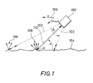
- Fig. 1 are the arrangement of an ultrasonic transducer and the emitted or reflected signals are shown.
- the ultrasonic transducer 100 has a broad radiation characteristic with an opening angle ⁇ .
- the converter 100 sends ultrasonic signals 102 in the area of its opening angle ⁇ off. These emitted signals 102 hit one rough surface 104 and are reflected on it. Dependent from the angular adjustment of the converter the emitted signals 102 at an angle a surface 104.
- the signals 102 striking the rough surface 104 are reflected on this. It is about a diffuse reflection of the signal on surface 104, as shown by reference numeral 108. On Portion 110 of the reflected signals is from converter 100 receive.
- the converter 100 be sufficiently wide Has sensitivity characteristic, that is, the half the opening angle ⁇ / 2 of the transducer is greater than that Irradiation angle ⁇ , so that the diffuse reflection of Signals 102 on the surface of a spectral portion of the Doppler shift Signal exists that from the radiation angle is independent. This is the highest frequency component that occurs in the Doppler spectrum. This frequency component represents is a direct measure of speed.
- the acquisition of the spectral component and the derivation of the speed can be done by a variety of methods become. Such methods include, for example conventional spectral analysis methods or the Fourier transformation on.
- the steps of acquiring the spectral component and deriving the speed comprise a plurality of substeps.
- a first sub-step a lower one Cut-off frequency of a high-pass filter set to a frequency which is greater than the frequency of the radiated Signal 102, and the received signal 110 is replaced by the Filtered high pass filter.
- the next step is the signal power at the output of the high-pass filter is detected and with a predetermined signal power compared.
- the signal power is less than that predetermined signal power, becomes the lower limit frequency of the high-pass filter is lowered by a predetermined value and the steps of filtering, capturing and comparing are repeated.
- the set lower Limit frequency of the high-pass filter output In the event that the signal power is greater than or equal to that is the specified signal power, the set lower Limit frequency of the high-pass filter output, and this is converted into a quantity that represents the speed.
- a fluctuation occurs due to the constant movement of the ski the distance between the transducer 100 and the snow surface on.
- these can Fluctuations after high pass filtering of the received signal 102 by amplifying the filtered signal using a Balanced amplifier with automatic gain control become.
- this is on a Display device displayed.
- the steps of capturing the Spectral component, the derivation of the speed and the Displaying this speed can be done in one place which is spaced from transducer 100.
- the one for speed measurement required data, for example by means of an electromagnetic transmission to a separately arranged unit, which can be found on Wrist or as a head-up display in the skier's helmet located.
- display units can also be used that directly are attached to the ski.
- the detection and discharge device shown in FIG. 2, which are designated in their entirety by reference number 200 is the spectral component with the highest Frequency that exceeds a predetermined energy value, from the Doppler spectrum of the received signal 110 to grasp and the speed from the frequency of the derived spectral component.
- SC filter switched capacitor filter
- This high-pass filter 202 has a lower cut-off frequency f x , which is adjustable.
- the lower limit frequency is set via a voltage-controlled clock oscillator 204, the voltage of which is controlled by a sawtooth voltage generator 206 and a square-wave voltage generator 208.
- the generators 206 and 208 also apply their voltages to a conversion and display unit 210.
- the received signal 110 is applied to the high-pass filter 202 and that present at the output of the high-pass filter 202 Signal is through a low pass filter 212 and a squaring circuit 214 to an input of a comparator circuit 216 created.
- the comparator 216 compares the signal power present at its input with a predetermined signal power. As soon as the applied signal power exceeds the predetermined signal power, the comparator 216 switches and the conversion and display unit 210 converts the limit frequency f x set on the high-pass filter 202 into the speed and displays it.
- the detection and derivation device 200 can additionally a so-called amplifier with automatic gain control include (not shown in Fig. 2), the between the high pass filter 202 and the low pass filter 212 is switched. This amplifier serves fluctuations compensate for the distance between the transducer and the surface, that occur constantly while using a ski.
- Fig. 3 shows a further embodiment of the invention Device in which the received signal 110 was mixed down into the baseband and to a speed dependent Amplifier is applied to the weight received signal depending on the speed. This ensures that the detection and discharge device 200 signals are always created that are in the have essentially the same level.
- the through the Device 200 calculated speed is on the amplifier 300 for weighting the next received signal fed back via a line 302.
- the conversion and display unit 210 described above records the travel times according to a further exemplary embodiment, so that a calculation of the distance traveled is possible. There is also a storage of the maximum speeds and from that a calculation of the average speed possible.
- FIG. 4a shows the front section of a ski 400, the converter 100 is arranged at the tip 402 thereof. Further the opening angle ⁇ of the converter 100 is shown.
- the Transducer 100 can either be placed on top of the ski be so that a hole in the ski must be provided to not to hinder radiation from the transducer 100, or transducer 100 can be located directly on the underside of the ski tip be arranged.
- the acquisition and discharge device 200 can be on the top of the ski tip.
- the detection and derivation device 200 can also be removed be arranged by the converter 100, for example from be carried to the skier.
- Fig. 4b shows another way of attaching the Converter 100.
- converter 100 at the rear 404 of the ski 400 arranged. So that the converter 100 radiate freely can, it must be arranged at the very end of the ski 400. If this arrangement is the ski most of the time in contact with the ground possible because the problem of drifts of the received Signal then does not occur.
- the spectral component is not included the highest frequency that has a given energy value exceeds the basis for calculating the speed, but it is the spectral component with the lowest frequency that has a given energy value exceeds.
- the signal power present at the output of filter 202 is compared with a given signal power. If the signal power is less than the specified one Signal power, the upper cutoff frequency of the Filters 202 increased by a predetermined value and the previous steps are repeated. If the signal power greater than or equal to the specified signal power the set upper limit frequency of the Filters 202 output and converted to a size that represents the speed.
- the present invention not on the use of a high-pass filter or low-pass filter for capturing the spectral components of interest of the Doppler spectrum of the received signal is limited.
- the use of a bandpass filter with one setting the corresponding cut-off frequency or center frequency also possible.
Landscapes
- Engineering & Computer Science (AREA)
- Radar, Positioning & Navigation (AREA)
- Remote Sensing (AREA)
- Physics & Mathematics (AREA)
- General Physics & Mathematics (AREA)
- Computer Networks & Wireless Communication (AREA)
- Acoustics & Sound (AREA)
- Radar Systems Or Details Thereof (AREA)
- Measurement Of Velocity Or Position Using Acoustic Or Ultrasonic Waves (AREA)
- Analysing Materials By The Use Of Radiation (AREA)
Abstract
Description
Die vorliegende Erfindung bezieht sich auf ein Verfahren und eine Vorrichtung zur berührungslosen Geschwindigkeitsmessung auf Oberflächen, insbesondere zur Ski-Geschwindigkeitsmessung auf Schneeoberflächen.The present invention relates to a method and a device for non-contact speed measurement on surfaces, especially for ski speed measurement on snow surfaces.
Mit der zunehmenden Verbreitung des Skifahrens als Breitensport wächst die Nachfrage nach bestimmten Geräten für diesen Massensport, die eine Aussage über eine erbrachte Leistung ermöglichen. Im allgemeinen ist es für einen Sportler wünschenswert, seine Leistung kontrollieren zu können und hierfür aussagekräftige Daten zur Verfügung zu haben. Insbesondere sind nach Ableistung eines bestimmten Pensums Aussagen über die gefahrene Strecke, über die durchschnittliche Geschwindigkeit, über die höchste gefahrene Geschwindigkeit usw. sowohl für Abfahrtskifahrer als auch für Langläufer von Interesse.With the increasing spread of skiing as a popular sport the demand for certain devices for this grows Mass sport, which is a statement of an achievement enable. Generally it is for an athlete desirable to be able to control its performance and to have meaningful data available for this. In particular are statements after a certain amount of work has been done over the distance traveled, over the average Speed, above the highest speed traveled etc. for downhill skiers as well as for cross-country skiers from Interest.
Bisher existieren auf dem Markt keine Systeme, die einem Skifahrer diese Daten bereitstellen. Bekannte Verfahren zur Ski-Geschwindigkeitsmessung weisen eine Vielzahl von Nachteilen auf. Sie sind entweder sehr störanfällig oder ungenau, aufgrund der verwendeten mechanischen Verfahren. Ferner ist es nicht möglich, den notwendigen Geschwindigkeitsbereich vollständig abzudecken.So far there are no systems on the market that Provide skiers with this information. Known methods for Ski speed measurement have a number of disadvantages on. They are either very prone to failure or inaccurate, due to the mechanical processes used. Further it is not possible to find the necessary speed range to cover completely.
Für andere Anwendungen der Geschwindigkeitsmessung sind Verfahren nach dem Ultraschall-Doppler-Prinzip bekannt. Bei diesen Verfahren tritt jedoch das Problem der Abhängigkeit der dopplerverschobenen Frequenz vom Winkel zwischen dem Ultraschall-Wandler und der sich am Wandler vorbeibewegenden Oberfläche, deren Geschwindigkeit gemessen werden soll, auf.There are methods for other speed measurement applications known according to the ultrasound Doppler principle. At However, these methods encounter the problem of dependency the Doppler shifted frequency from the angle between the ultrasound transducer and the one moving past the converter Surface whose speed is to be measured.
Im Stand der Technik wird vorgeschlagen, zur Kompensation dieser Auswirkung eine sogenannte Janus-Anordnung zu verwenden, mit deren Hilfe die Winkelabhängigkeit kompensiert werden kann. Diese Anordnung hat den Nachteil, daß zwei Ultraschall-Wandler notwendig sind, die einen festen Winkel zueinander einschließen. Dies verursacht einerseits höhere Kosten und andererseits treten, vor allem bei einem nach hinten gerichteten Wandler, leichter Verwehungen des Schalls auf. Solche Verwehungen beeinträchtigen eine genaue Messung von höheren Geschwindigkeiten.In the prior art it is proposed for compensation to use a so-called Janus arrangement, with the help of which the angle dependency is compensated can. This arrangement has the disadvantage that two ultrasonic transducers are necessary that have a fixed angle to each other lock in. On the one hand, this causes higher ones Costs and on the other hand occur, especially with one rear-facing transducer, slight drifts of sound on. Such drifts interfere with an accurate measurement of higher speeds.
Die US-A-4,757,714 offenbart einen Geschwindigkeitssensor und eine auf einem Helm befestigte Datenanzeige. Ein Sender ist an einem Ski befestigt und sendet Ultraschall- oder elektromagnetische Wellen in Richtung des stationären Mediums aus, über das sich ein Skifahrer bewegt. Ein Element des selben Senders oder ein getrennter Wandler erfaßt Wellen, die von dem stationären Medium reflektiert werden. Ein Computer berechnet die Geschwindigkeit der Ski aus der Dopplerverschiebung des reflektierten Signals und aktiviert eine Anzeigeeinheit, um die Geschwindigkeit anzuzeigen.US-A-4,757,714 discloses a speed sensor and a data display attached to a helmet. A transmitter is attached to a ski and sends ultrasound or electromagnetic waves towards the stationary Medium over which a skier moves. An element of the same transmitter or a separate converter Waves that are reflected by the stationary medium. A computer calculates the speed of the skis from the Doppler shift of the reflected signal and activated a display unit to show the speed.
Es ist die Aufgabe der vorliegenden Erfindung, ein Verfahren und eine Vorrichtung zur berührungslosen Geschwindigkeitsmessung auf Oberflächen, insbesondere zur Ski-Geschwindigkeitsmessung auf Schneeoberflächen, zu schaffen, die eine genaue Messung der Geschwindigkeit über den erforderlichen Geschwindigkeitsbereich ermöglichen, die eine geringe Störanfälligkeit aufweisen, wobei die Vorrichtung auf einfache Art und Weise mit niedrigen Kosten herstellbar ist, und bei denen keine Verwehungen des Schalls auftreten.It is the object of the present invention, a method and a device for non-contact speed measurement on surfaces, especially for ski speed measurement on snow surfaces, to create one accurate measurement of speed over the required Allow speed range that is low susceptibility to interference have, the device with in a simple manner low cost is producible, and with no drifts of sound occur.
Diese Aufgabe wird durch ein Verfahren nach Anspruch 1 und nach Anspruch 3 und durch eine Vorrichtung nach Anspruch 12 und nach Anspruch 13 gelöst. This object is achieved by a method according to claim 1 and according to claim 3 and by a device according to claim 12 and solved according to claim 13.
Die vorliegende Erfindung schafft ein Verfahren zur berührungslosen
Geschwindigkeitsmessung auf Oberflächen, insbesondere
zur Ski-Geschwindigkeitsmessung auf Schneeoberflächen,
mit folgenden Schritten:
Die vorliegende Erfindung schafft eine Vorrichtung zur berührungslosen
Geschwindigkeitsmessung auf Oberflächen, insbesondere
zur Ski-Geschwindigkeitsmessung auf Schneeoberflächen,
mit
Die vorliegende Erfindung schafft ein Verfahren zur berührungslosen
Geschwindigkeitsmessung auf Oberflächen, insbesondere
zur Ski-Geschwindigkeitsmesseung auf Schneeoberflächen,
mit folgenden Verfahrensschritten:
Die vorliegende Erfindung schafft eine Vorrichtung zur berührungslosen
Geschwindigkeitsmessung auf Oberflächen, insbesondere
zur Ski-Geschwindigkeitsmessung auf Schneeoberflächen,
mit
Ein Vorteil der vorliegenden Erfindung besteht darin, daß gleichzeitig während des Fahrens die dazu benötigte Zeit gemessen werden kann, so daß eine Berechnung der zurückgelegten Strecke möglich ist. Ferner können die erreichten Maximalwerte für die Geschwindigkeit gespeichert werden, und die Durchschnittsgeschwindigkeit kann berechnet werden.An advantage of the present invention is that the time required for this is measured simultaneously while driving can be, so that a calculation of the distance traveled Route is possible. Furthermore, the maximum values reached for the speed to be saved, and the Average speed can be calculated.
Ein weiterer Vorteil der vorliegenden Erfindung besteht darin, daß eine Kompensation der Winkelabhängigkeit des Dopplereffekts mit nur einem Wandler möglich ist, so daß das System wesentlich kostengünstiger hergestellt werden kann als ein System, das eine Janus-Anordnung von zwei Wandlern aufweist.Another advantage of the present invention is that compensation for the angular dependence of the Doppler effect is possible with only one converter, so the system can be produced much cheaper than a system that has a Janus arrangement of two transducers.
Weitere Ausgestaltungen der vorliegenden Erfindung sind in den Unteransprüchen definiert.Further refinements of the present invention are in the sub-claims defined.
Anhand der beiliegenden Zeichnungen werden nachfolgend bevorzugte Ausführungsbeispiele der vorliegenden Erfindung näher erläutert. Es zeigen:
- Fig. 1
- eine Darstellung der Anordnung des Ultraschallwandlers und der abgestrahlten und reflektierten Signale;
- Fig. 2
- ein Blockdiagramm der Erfassungs- und Ableiteinrichtung gemäß einem Ausführungsbeispiel der vorliegenden Erfindung;
- Fig. 3
- ein Blockdiagramm eines weiteren Ausführungsbeispiels der erfindungsgemäßen Vorrichtung; und
- Fig. 4a
- und 4b eine Anordnung der erfindungsgemäßen Vorrichtung auf einem Ski.
- Fig. 1
- a representation of the arrangement of the ultrasonic transducer and the emitted and reflected signals;
- Fig. 2
- a block diagram of the detection and deriving device according to an embodiment of the present invention;
- Fig. 3
- a block diagram of another embodiment of the device according to the invention; and
- Fig. 4a
- and FIG. 4b an arrangement of the device according to the invention on a ski.
Messungen nach dem Dopplerprinzip basieren darauf, daß eine diffuse Reflexion eines abgestrahlten Signals, z. B. eines Schallsignals, an der zu messenden Oberfläche auftritt. Diese Reflexion ist dann besonders stark ausgeprägt, wenn die Wellenlänge des Signals in der gleichen Größenordnung ist wie die Rauhigkeit der bestrahlten Oberfläche.Measurements according to the Doppler principle are based on the fact that a diffuse reflection of a radiated signal, e.g. B. one Sound signal that occurs on the surface to be measured. This Reflection is particularly pronounced when the Wavelength of the signal is of the same order of magnitude like the roughness of the irradiated surface.
Für Schneeoberflächen ist bei gewalzten Pisten mit einer Auflage von kleinen Brocken mit Durchmessern von einigen Millimetern bis zu wenigen Zentimetern zu rechnen, so daß sich hier beispielsweise der Einsatz von Ultraschall mit Frequenzen von ca. 40 kHz bis 200 kHz optimal eignet.For snow surfaces with rolled slopes is one Edition of small chunks with diameters of a few To calculate millimeters to a few centimeters, so that the use of ultrasound, for example Frequencies from approx. 40 kHz to 200 kHz are ideal.
In Fig. 1 sind die Anordnung eines Ultraschallwandlers und
die abgestrahlten bzw. reflektierten Signale dargestellt.
Der Ultraschallwandler 100 weist eine breite Abstrahlcharakteristik
mit einem Öffnungswinkel auf. Der Wandler 100
sendet Ultraschallsignale 102 im Bereich seines Öffnungswinkels
aus. Diese abgestrahlten Signale 102 treffen auf eine
rauhe Oberfläche 104 und werden an dieser reflektiert. Abhängig
von der winkelmäßigen Einstellung des Wandlers treffen
die abgestrahlten Signale 102 unter einem Winkel a auf
der Oberfläche 104 auf.In Fig. 1 are the arrangement of an ultrasonic transducer and
the emitted or reflected signals are shown.
The
Wie es in Fig. 1 durch den Pfeil 106 dargestellt ist, erfolgt
die Abstrahlung des Wandlers 100 in der Fahrtrichtung.As shown in FIG. 1 by
Die auf die rauhe Oberfläche 104 auftreffenden Signale 102
werden an dieser reflektiert. Es handelt sich hierbei um
eine diffuse Reflexion des Signals an der Oberfläche 104,
wie dies durch das Bezugszeichen 108 dargestellt ist. Ein
Teil 110 der reflektierten Signale wird von dem Wandler 100
empfangen.The
Zur Durchführung des erfindungsgemäßen Verfahrens ist es
zwingend, daß der Wandler 100 eine ausreichend breite
Empfindlichkeitscharakteristik aufweist, das heißt, daß der
halbe Öffnungswinkel /2 des Wandlers größer ist als der
Bestrahlungswinkel α, so daß bei der diffusen Reflexion der
Signale 102 an der Oberfläche ein Spektralanteil des dopplerverschobenen
Signals existiert, der vom Bestrahlungswinkel
unabhängig ist. Dies ist der höchste, auftretende Frequenzanteil
im Dopplerspektrum. Dieser Frequenzanteil stellt
ein direktes Maß für die Geschwindigkeit dar.It is to carry out the method according to the invention
imperative that the
Nachdem im vorhergehenden die Voraussetzungen zur Realisierung der vorliegenden Erfindung kurz dargelegt wurden, folgt nun eine Beschreibung des erfindungsgemäßen Verfahrens.After the prerequisites for realization of the present invention briefly follows now a description of the method according to the invention.
In einem ersten Schritt wird ein Signal 102 mit einer festen
Frequenz in Fahrtrichtung und unter einem Bestrahlungswinkel
α abgestrahlt, wobei der Bestrahlungswinkel α kleiner ist
als ein halber Öffnungswinkel 6/2 des Wandlers 100. Nach dem
Empfangen des an der Oberfläche 104 reflektierten Signals
110, das bezüglich des abgestrahlten Signals 102 dopplerverschoben
ist, wird der Spektralanteil mit der höchsten Frequenz,
der einen vorgegebenen Energiewert übersteigt, aus
dem Dopplerspektrum des empfangenen Signals 110 erfaßt und
die Geschwindigkeit wird aus der Frequenz des erfaßten Spektralanteils
abgeleitet.In a first step, a
Die Erfassung des Spektralanteils und die Ableitung der Geschwindigkeit kann durch eine Mehrzahl von Verfahren durchgeführt werden. Solche Verfahren schließen beispielsweise herkömmliche Spektralanalyseverfahren oder die Fouriertransformation ein.The acquisition of the spectral component and the derivation of the speed can be done by a variety of methods become. Such methods include, for example conventional spectral analysis methods or the Fourier transformation on.
Nachfolgend wird ein Verfahren gemäß einem bevorzugten Ausführungsbeispiel der vorliegenden Erfindung näher beschrieben.The following is a method according to a preferred embodiment of the present invention described in more detail.
Die Schritte des Erfassens des Spektralanteils und des Ableitens
der Geschwindigkeit umfassen eine Mehrzahl von Teilschritten.
In einem ersten Teilschritt wird eine untere
Grenzfrequenz eines Hochpaßfilters auf eine Frequenz eingestellt,
die größer ist als die Frequenz des abgestrahlten
Signals 102, und das empfangene Signal 110 wird durch das
Hochpaßfilter gefiltert. Dieses Hochpaßfilter kann gemäß
einem Ausführungsbeispiel der vorliegenden Erfindung ein sogenanntes
SC-Hochpaßfilter sein (SC-Filter = Schalterkondensatorfilter).The steps of acquiring the spectral component and deriving
the speed comprise a plurality of substeps.
In a first sub-step, a lower one
Cut-off frequency of a high-pass filter set to a frequency
which is greater than the frequency of the radiated
In einem nächsten Schritt wird die Signalleistung am Ausgang des Hochpaßfilters erfaßt und mit einer vorgegebenen Signalleistung verglichen.The next step is the signal power at the output of the high-pass filter is detected and with a predetermined signal power compared.
In dem Fall, in dem die Signalleistung kleiner ist als die vorgegebene Signalleistung, wird die untere Grenzfrequenz des Hochpaßfilters um einen vorbestimmten Wert erniedrigt und die Schritte des Filterns, Erfassens und Vergleichens werden wiederholt.In the case where the signal power is less than that predetermined signal power, becomes the lower limit frequency of the high-pass filter is lowered by a predetermined value and the steps of filtering, capturing and comparing are repeated.
Für den Fall, daß die Signalleistung größer oder gleich der vorgegebenen Signalleistung ist, wird die eingestellte untere Grenzfrequenz des Hochpaßfilters ausgegeben, und diese wird in eine Größe umgewandelt, die die Geschwindigkeit darstellt.In the event that the signal power is greater than or equal to that is the specified signal power, the set lower Limit frequency of the high-pass filter output, and this is converted into a quantity that represents the speed.
Durch die ständige Bewegung des Skis tritt eine Schwankung
des Abstandes zwischen dem Wandler 100 und der Schneeoberfläche
auf.A fluctuation occurs due to the constant movement of the ski
the distance between the
Gemäß einem weiteren Ausführungsbeispiel können diese
Schwankungen nach dem Hochpaßfiltern des empfangenen Signals
102 durch Verstärken des gefilterten Signals mittels eines
Verstärkers mit automatischer Verstärkungsregelung ausgeglichen
werden.According to a further exemplary embodiment, these can
Fluctuations after high pass filtering of the received
Unabhängig davon, welche Art der Erfassung des Spektralanteils
gewählt wird, kann vor dem Schritt des Erfassens dieses
Spektralanteils das empfangene Signal 110 in das Basisband
hinuntergemischt und das empfangene Signal 110 kann
durch ein geschwindigkeitsabhängiges Verstärken derart gewichtet
werden, daß beim Erfassen des Spektralanteils immer
Signale anliegen, die im wesentlichen den gleichen Pegel
aufweisen.Regardless of what type of acquisition of the spectral component
can be selected before the step of capturing this
Spectral component received
Nach der Ableitung der Geschwindigkeit wird diese auf einer
Anzeigevorrichtung angezeigt. Die Schritte des Erfassens des
Spektralanteils, des Ableitens der Geschwindigkeit und des
Anzeigens dieser Geschwindigkeit können an einem Ort erfolgen,
der von dem Wandler 100 beabstandet ist. Die zur Geschwindigkeitsmessung
erforderlichen Daten können beispielsweise
mittels einer elektromagnetischen Übertragung an eine
getrennt angeordnete Einheit vermittelt werden, die sich am
Handgelenk oder als Head-Up-Display im Helm des Skifahrers
befindet.After the derivation of the speed, this is on a
Display device displayed. The steps of capturing the
Spectral component, the derivation of the speed and the
Displaying this speed can be done in one place
which is spaced from
Wenn eine solche entfernte Anordnung nicht erwünscht ist, können auch Anzeigeeinheiten verwendet werden, die direkt auf dem Ski angebracht sind.If such a remote arrangement is not desired, display units can also be used that directly are attached to the ski.
Anhand der Fig. 2 wird nun ein Blockdiagramm einer Erfassungs- und Ableiteinrichtung gemäß einem bevorzugten Ausführungsbeispiel der vorliegenden Erfindung näher beschrieben.2, a block diagram of a detection and discharge device according to a preferred embodiment of the present invention described in more detail.
Die in Fig. 2 dargestellte Erfassungs- und Ableiteinrichtung,
die in ihrer Gesamtheit mit dem Bezugszeichen 200 bezeichnet
ist, dient dazu, den Spektralanteil mit der höchsten
Frequenz, der einen vorgegebenen Energiewert übersteigt,
aus dem Dopplerspektrum des empfangenen Signals 110
zu erfassen, und die Geschwindigkeit aus der Frequenz des
empfangenen Spektralanteils abzuleiten.The detection and discharge device shown in FIG. 2,
which are designated in their entirety by
Die Einrichtung 200 umfaßt ein sogenanntes SC-Hochpaßfilter
202 (SC-Filter = Schalterkondensatorfilter). Dieses Hochpaßfilter
202 weist eine untere Grenzfrequenz fx auf, die einstellbar
ist. Die Einstellung der unteren Grenzfrequenz erfolgt
über einen spannungsgesteuerten Taktoszillator 204,
dessen Spannung durch einen Sägezahnspannungsgenerator 206
und einen Rechteckspannungsgenerator 208 gesteuert wird. Die
Generatoren 206 und 208 legen ihre Spannungen ebenfalls an
eine Umwandlungs- und Anzeigeeinheit 210 an.The
An das Hochpaßfilter 202 wird das empfangene Signale 110 angelegt
und das am Ausgang des Hochpaßfilters 202 anliegende
Signal wird über ein Tiefpaßfilter 212 und über eine Quadriererschaltung
214 an einen Eingang einer Komparatorschaltung
216 angelegt.The received
Der Komparator 216 vergleicht die an seinem Eingang anliegende
Signalleistung mit einer vorgegebenen Signalleistung.
Sobald die anliegende Signalleistung die vorgegebene Signalleistung
überschreitet, schaltet der Komparator 216 und die
Umwandlungs- und Anzeigeeinheit 210 wandelt die am Hochpaßfilter
202 eingestellte Grenzfrequenz fx in die Geschwindigkeit
um und zeigt diese an.The
Die Erfassungs- und Ableiteinrichtung 200 kann zusätzlich
einen sogenannten Verstärker mit automatischer Verstärkungsregelung
einschließen (in Fig. 2 nicht dargestellt), der
zwischen das Hochpaßfilter 202 und das Tiefpaßfilter 212
geschaltet ist. Dieser Verstärker dient dazu, Schwankungen
des Abstandes zwischen dem Wandler und der Oberfläche auszugleichen,
die während der Benutzung eines Skis ständig auftreten.The detection and
Fig. 3 zeigt ein weiteres Ausführungsbeispiel der erfindungsgemäßen
Vorrichtung, bei dem das empfangene Signal 110
in das Basisband hinuntergemischt wurde und an einen geschwindigkeitsabhängigen
Verstärker angelegt wird, um das
empfangene Signal abhängig von der Geschwindigkeit zu gewichten.
Dies stellt sicher, daß an die Erfassungs- und Ableiteinrichtung
200 immer Signale angelegt werden, die im
wesentlichen einen gleichen Pegel aufweisen. Die durch die
Einrichtung 200 berechnete Geschwindigkeit wird an dem Verstärker
300 zur Gewichtung des nächsten empfangenen Signals
über eine Leitung 302 zurückgeführt.Fig. 3 shows a further embodiment of the invention
Device in which the received
Die oben beschriebene Umwandlungs- und Anzeigeeinheit 210
erfaßt gemäß einem weiteren Ausführungsbeispiel die Fahrzeiten,
so daß eine Berechnung der zurückgelegten Strecke
möglich ist. Ferner ist eine Speicherung der Maximalgeschwindigkeiten
und daraus eine Berechnung der Durchschnittsgeschwindigkeit
möglich.The conversion and
In Fig. 4a ist der vordere Abschnitt eines Skis 400 gezeigt,
an dessen Spitze 402 der Wandler 100 angeordnet ist. Ferner
ist der Öffnungswinkel des Wandlers 100 dargestellt. Der
Wandler 100 kann entweder auf der Oberseite des Ski angeordnet
sein, so daß ein Loch im Ski vorgesehen sein muß, um
eine Abstrahlung des Wandlers 100 nicht zu behindern, oder
der Wandler 100 kann unmittelbar an der Unterseite der Skispitze
angeordnet sein. Die Erfassungs- und Ableiteinrichtung
200 kann sich auf der Oberseite der Skispitze befinden.
Die Erfassungs- und Ableiteinrichtung 200 kann auch entfernt
vom Wandler 100 angeordnet sein, sie kann zum Beispiel von
dem Skifahrer getragen werden.4a shows the front section of a
Fig. 4b zeigt eine weitere Möglichkeit der Anbringung des
Wandlers 100. Hier ist der Wandler 100 am hinteren Teil 404
des Skis 400 angeordnet. Damit der Wandler 100 frei strahlen
kann, muß er ganz am Ende des Skis 400 angeordnet sein. Wenn
der Ski die meiste Zeit Kontakt zum Boden hat, ist diese Anordnung
möglich, da das Problem von Verwehungen des empfangenen
Signals hierbei dann nicht auftritt.Fig. 4b shows another way of attaching the
Es wird darauf hingewiesen, daß in diesem Fall die Dopplerfrequenz zu niedrigen Frequenzen, verglichen mit der Sendefrequenz, verschoben wird.It should be noted that in this case the Doppler frequency too low frequencies compared to the transmission frequency, is moved.
In diesem Fall ist jedoch nicht derjenige Spektralanteil mit der höchsten Frequenz, der einen vorgegebenen Energiewert übersteigt, die Grundlage zur Berechnung der Geschwindigkeit, sondern es ist derjenige Spektralanteil mit der niedrigsten Frequenz, der einen vorgegebenen Energiewert übersteigt.In this case, however, the spectral component is not included the highest frequency that has a given energy value exceeds the basis for calculating the speed, but it is the spectral component with the lowest frequency that has a given energy value exceeds.
Dies bedeutet für das oben beschriebene Ausführungsbeispiel,
daß anstelle eines Hochpaßfilters ein Tiefpaßfilter verwendet
wird. Dessen Grenzfrequenz wird auf eine Frequenz eingestellt,
die niedriger ist als die Frequenz des abgestrahlten
Signals. Die am Ausgang des Filters 202 anliegende Signalleistung
wird mit einer vorgegebenen Signalleistung verglichen.
Falls die Signalleistung kleiner ist als die vorgegebene
Signalleistung, wird die obere Grenzfrequenz des
Filters 202 um einen vorbestimmten Wert erhöht und die
vorangegangenen Schritte werden wiederholt. Falls die Signalleistung
größer oder gleich der vorgegebenen Signalleistung
ist, wird die eingestellte obere Grenzfrequenz des
Filters 202 ausgegeben und in eine Größe umgewandelt, die
die Geschwindigkeit darstellt.For the exemplary embodiment described above, this means
that uses a low-pass filter instead of a high-pass filter
becomes. Its cutoff frequency is set to a frequency
which is lower than the frequency of the radiated
Signal. The signal power present at the output of
Alle im vorhergehenden, mit Bezug auf einen Wandler 100, der
in Fahrtrichtung abstrahlt, gemachten Ausführungen gelten
auf gleiche Weise für den Wandler 100 aus Fig. 4b, der entgegengesetzt
der Fahrtrichtung abstrahlt.All of the foregoing, with reference to a
Obwohl die oben beschriebenen Ausführungsbeispiele im Zusammenhang mit einem Ultraschallwandler beschrieben wurden, ist es offensichtlich, daß abhängig von der Oberfläche auch andere Einrichtungen zu der Erzeugung von Signalen und zum Aufnehmen von reflektierten Signalen, die dopplerverschoben sind, geeignet sind.Although the above-described embodiments are related with an ultrasound transducer it is obvious that depending on the surface also others Devices for generating signals and for recording of reflected signals that are shifted Doppler, are suitable.
Es wird darauf hingewiesen, daß die vorliegende Erfindung nicht auf die Verwendung eines Hochpaßfilters oder Tiefpaßfilters zum Erfassen der interessierenden Spektralanteile des Dopplerspektrums des empfangenen Signals beschränkt ist. Die Verwendung eines Bandpaßfilters mit einer Einstellung der entsprechenden Grenzfrequenz bzw. Mittenfrequenz ist ebenfalls möglich. It should be noted that the present invention not on the use of a high-pass filter or low-pass filter for capturing the spectral components of interest of the Doppler spectrum of the received signal is limited. The use of a bandpass filter with one setting the corresponding cut-off frequency or center frequency also possible.
Es wird darauf hingewiesen, daß es zur Ausführung des erfindungsgemäßen Verfahrens oder der erfindungsgemäßen Vorrichtung erforderlich ist, temperaturstabile und robuste Bauelemente zu verwenden, die die beim Skifahren auftretenden Minustemperaturen und Erschütterungen ohne Schaden überstehen.It should be noted that it is for the execution of the invention Method or the device according to the invention is required, temperature stable and robust To use components that occur when skiing Freezing temperatures and shocks without damage survive.
Claims (26)
- A method for non-contactual speed measurement on surfaces, in particular for skiing speed measurement on snow surfaces, comprising the following method steps:a) radiating a signal (102) of a fixed frequency in the direction of motion (106) at an irradiation angle (α), the irradiation angle (α) being smaller than a half aperture angle (Θ/2) of a means (100) radiating the signal (102);b) receiving a signal (110) reflected at the surface (104) which is Doppler-shifted with respect to the radiated signal (102);c) detecting the spectral portion with the highest frequency, and which exceeds a specified energy value, from the Doppler spectrum of the received signal (110); andd) deducing the speed from the frequency of the detected spectral portion.
- A method according to claim 1, characterized in
that detecting the spectral portion and deducing the speed comprises the following steps:c1) setting a lower threshold frequency (fx) of a high-pass filter to a frequency which is greater than the frequency of the radiated signal (102);c2) high-pass filtering of the received signal (110);c3) detecting the signal power at the output of the high-pass filter (202); andc4) comparing the signal power with a specified signal power;c4.1) if the signal power is smaller than the specified signal power:c4.1.1) reducing the lower threshold frequency (fx) of the high-pass filter (202) by a predetermined value; andc4.1.2) repeating the steps c2) to c4);c4.2) if the signal power is greater than or equal to the specified signal power:c4.2.1) outputting the lower threshold frequency (fx) which has been set for the high-pass filter (202); andc4.2.2) converting the lower threshold frequency (fx) which has been output to a quantity representing the speed. - A method for non-contactual speed measurement on surfaces, in particular for skiing speed measurement on snow surfaces, comprising the following method steps:a) radiating a signal (102) of a fixed frequency against the direction of motion at an irradiation angle (α), the irradiation angle (α) being smaller than a half aperture angle (Θ/2) of a means (100) radiating the signal;b) receiving a signal (110) reflected at the surface (104) which is Doppler-shifted with respect to the radiated signal (102);c) detecting the spectral portion with the lowest frequency, and which exceeds a specified energy value, from the Doppler spectrum of the received signal; andd) deducing the speed from the frequency of the detected spectral portion.
- A method according to claim 3, characterized in
that detecting the spectral portion and deducing the speed comprises the following steps:c1) setting an upper threshold frequency (fx) of a low-pass filter (202) to a frequency which is smaller than the frequency of the radiated signal (102);c2) low-pass filtering of the received signal (110);c3) detecting the signal power at the output of the low-pass filter (202); andc4) comparing the signal power with a specified signal power;c4.1) if the signal power is smaller than the specified signal power:c4.2) if the signal power is greater than or equal to the specified signal power:c4.1.1) increasing the upper threshold frequency (fx) of the low-pass filter (202) by a predetermined value; andc4.1.2) repeating the steps c2) to c4);c4.2.1) outputting the upper threshold frequency (fx) which has been set for the low-pass filter (202); andc4.2.2) converting the upper threshold frequency which has been output to a quantity representing the speed. - A method according to claim 2 or 4, characterized by the following method step before the step c2):
amplifying the received signal using an amplifier with automatic gain control so as to compensate for the fluctuations in the distance between the means radiating the signal (100) and the surface (104). - A method according to claim 2, 4 or 5, characterized in
that the high-pass filter (202) or the low-pass filter is implemented by means of a switched capacitor filter. - A method according to claim 1 or 3, characterized in
that the step of detecting the spectral portion and deducing the speed involves a Fourier transform. - A method according to one of the claims 1 to 7, characterized by the following method steps before the step c):down-converting the received signal (110) to the baseband; andweighting the received signal (110) using a speed-dependent amplification (300), so that signals with essentially the same levels are always available for detecting the spectral portion.
- A method according to one of the claims 1 to 8, characterized by the following method step:e) displaying the measured speed on a display device (210).
- A method according to claim 9, characterized in
that step e) occurs at a location which is at a distance from the device (100) radiating the signal. - A method according to one of the claims 1 to 10, characterized inthat the radiated signal (102) is an ultrasonic signal; andthat the means (100) radiating the signal is an ultrasonic transducer.
- A device for non-contactual speed measurement on surfaces, in particular for skiing speed measurement on snow surfaces, characterized bya means (100) for radiating a signal (102) of fixed frequency in the direction of motion at an irradiation angle (α) and for receiving a Doppler-shifted signal (110) reflected at the surface (104), the irradiation angle (α) being smaller than a half aperture angle (Θ/2) of the means (100);a means (200) for detecting the spectral portion with the highest frequency, and which exceeds a specified energy value, from the Doppler spectrum of the received signal (110); anda means for deducing the speed from the frequency of the detected spectral portion.
- A device according to claim 12, characterized in
that the detection and deduction means (200) exhibits the following features:a high-pass filter (202), whose lower threshold frequency (fx) can be set and to which the received signal (110) can be applied, for which, starting at the threshold frequency (fx), which is higher than the frequency of the radiated signal (102), the threshold frequency (fx) can be reduced progressively until a signal power present at the output of the high-pass filter (202) exceeds a specified signal power;a comparator (216), which compares the signal power with the specified signal power;a conversion means (210) for converting a frequency at which the signal power at the high-pass filter output exceeds a specified signal power to a speed, anda display means (210) for displaying the speed. - A device for non-contactual speed measurement on surfaces, in particular for skiing speed measurement on snow surfaces, characterized bya means (100) for radiating a signal (102) of fixed frequency against the direction of motion at an irradiation angle (α) and for receiving a Doppler-shifted signal (110) reflected at the surface (104), the irradiation angle (α) being smaller than a half aperture angle (Θ/2) of the means (100);a means (200) for detecting the spectral portion with the lowest frequency, and which exceeds a specified energy value, from the Doppler spectrum of the received signal (110); anda means for deducing the speed from the frequency of the detected spectral portion.
- A device according to claim 14, characterized in
that the detection and deduction means (200) exhibits the following features:a low-pass filter (202), whose upper threshold frequency (fx) can be set and to which the received signal (110) can be applied, for which, starting at a threshold frequency (fx), which is lower than the frequency of the radiated signal (102), the threshold frequency (fx) can be increased progressively until a signal power present at the output of the low-pass filter (202) exceeds a specified signal power;a comparator (216), which compares the signal power with the specified signal power;a conversion means (210) for converting a frequency at which the signal power at the low-pass filter output exceeds the specified signal power to the speed; anda display means (210) for displaying the speed. - A device according to claim 13 or 15, characterized in thatthe threshold frequency (fx) of the high-pass filter (202) or the low-pass filter can be set by a voltage-controlled timing oscillator (204), which can be set via a sawtooth voltage generator (206) and a square-wave voltage generator (208), the generators (206, 208) being connected to the unit (210).a low-pass filter (212) and a squaring circuit (214) are circuited between the high-pass filter (202) or low-pass filter and the comparator (206).
- A device according to claim 13, 15 or 16 characterized in
that the output of the high-pass filter (202) is connected to an input of an amplifier with automatic gain control which compensates for fluctuations in the distance between the radiation means (100) and the surface (104). - A device according to claim 13, 15, 16 or 17, characterized in
that the high-pass filter (202) or low-pass filter takes the form of a switched capacitor filter. - A device according to claim 12 or 14, characterized in
that the means for detecting the spectral portions (200) performs a Fourier transform. - A device according to one of the claims 12 to 19, characterized bya downward-conversion means for transposing the received signal (110) to the baseband; anda speed-dependent amplifier (300) for weighting the received signal (110) so that signals with essentially the same levels are always present at the input of the means (200);where the downward-conversion means and the speed-dependent amplifier (300) are circuited between the radiation means and the means (200).
- A device according to one of the claims 12 to 20, characterized in
that the radiation means (100) and the means (200) for detecting the spectral portion and the means for deducing the speed are spatially separated fom one another. - A device according to one of the claims 12 to 21, characterized inthat the radiation means (100) is an ultrasonic transducer; andthat the radiated signal (102) is an ultrasonic signal.
- A device according to one of the claims 12 to 22, characterized in
that the receiving and deduction means (200) makes possible a calculation of the course covered, storage of the maximum speeds, a calculation of the average speed and a measurement of the travel time. - A ski (400), which exhibits a device according to one of the claims 12 or 13 and 16 to 23 when referring back to claim 11 or 12, characterized inthat the radiation means (100) is located in the neighbourhood of the ski tip (402) on the upper side of the ski, an opening being provided in the ski tip which makes it possible to radiate and receive signals in the direction of the snow surface; andthat the detection and deduction means (200) are located at a distance from the radiating means (100) on the ski (400) or may be carried by a user of the ski.
- A ski (400), which exhibits a device according to one of the claims 12 or 13 and 16 to 23 when referring back to claim 12 or 13, characterized inthat the radiation means (100) is located in the neighbourhood of the ski tip (402) on its lower side; andthat the detection and deduction means (200) are located at a distance from the radiating means (100) on the ski (400) or may be carried by a user of the ski.
- A ski (400), which exhibits a device according to one of the claims 14 or 15 and 16 to 23 when referring back to claim 14 or 15, characterized inthat the radiation means (100) is located on the upper side of the ski (400) at its rear end (404); andthat the detection and deduction means (200) are located at a distance from the radiating means (100) on the ski (400) or may be carried by a user of the ski.
Applications Claiming Priority (3)
| Application Number | Priority Date | Filing Date | Title |
|---|---|---|---|
| DE19501228A DE19501228C2 (en) | 1995-01-17 | 1995-01-17 | Method and device for non-contact speed measurement on surfaces |
| DE19501228 | 1995-01-17 | ||
| PCT/EP1995/004172 WO1996022549A1 (en) | 1995-01-17 | 1995-10-24 | Process and device for non-contact measurement of speed on surfaces |
Publications (3)
| Publication Number | Publication Date |
|---|---|
| EP0804745A1 EP0804745A1 (en) | 1997-11-05 |
| EP0804745B1 true EP0804745B1 (en) | 2000-01-26 |
| EP0804745B2 EP0804745B2 (en) | 2007-11-14 |
Family
ID=7751664
Family Applications (1)
| Application Number | Title | Priority Date | Filing Date |
|---|---|---|---|
| EP95937837A Expired - Lifetime EP0804745B2 (en) | 1995-01-17 | 1995-10-24 | Process and device for non-contact measurement of speed on surfaces |
Country Status (4)
| Country | Link |
|---|---|
| EP (1) | EP0804745B2 (en) |
| AT (1) | ATE189314T1 (en) |
| DE (2) | DE19501228C2 (en) |
| WO (1) | WO1996022549A1 (en) |
Families Citing this family (2)
| Publication number | Priority date | Publication date | Assignee | Title |
|---|---|---|---|---|
| GB9726719D0 (en) * | 1997-12-18 | 1998-02-18 | Bolton School | A ski speedometer |
| DE19914486C1 (en) * | 1999-03-30 | 2000-05-18 | Fraunhofer Ges Forschung | Arrangement for contactless speed measurement of an object moving across a surface detects component of combined Doppler spectrum with highest or lowest frequency and power level exceeding defined value |
Family Cites Families (4)
| Publication number | Priority date | Publication date | Assignee | Title |
|---|---|---|---|---|
| US4231039A (en) * | 1978-12-28 | 1980-10-28 | Glymar | Radar speedometer |
| US4660050A (en) * | 1983-04-06 | 1987-04-21 | Trw Inc. | Doppler radar velocity measurement horn |
| US4757714A (en) * | 1986-09-25 | 1988-07-19 | Insight, Inc. | Speed sensor and head-mounted data display |
| GB2276055B (en) † | 1993-03-12 | 1997-02-19 | Univ York | Speed measurement |
-
1995
- 1995-01-17 DE DE19501228A patent/DE19501228C2/en not_active Expired - Lifetime
- 1995-10-24 DE DE59507715T patent/DE59507715D1/en not_active Expired - Lifetime
- 1995-10-24 AT AT95937837T patent/ATE189314T1/en active
- 1995-10-24 WO PCT/EP1995/004172 patent/WO1996022549A1/en active IP Right Grant
- 1995-10-24 EP EP95937837A patent/EP0804745B2/en not_active Expired - Lifetime
Also Published As
| Publication number | Publication date |
|---|---|
| DE19501228A1 (en) | 1996-08-01 |
| DE59507715D1 (en) | 2000-03-02 |
| EP0804745B2 (en) | 2007-11-14 |
| DE19501228C2 (en) | 1997-02-20 |
| EP0804745A1 (en) | 1997-11-05 |
| WO1996022549A1 (en) | 1996-07-25 |
| ATE189314T1 (en) | 2000-02-15 |
Similar Documents
| Publication | Publication Date | Title |
|---|---|---|
| DE3204874C2 (en) | Passive method for obtaining target data from a sound source | |
| DE112013004908B4 (en) | Object detection device | |
| DE60306559T2 (en) | Method and device for determining air turbulence by means of bistatic measurements | |
| AT508562B1 (en) | 3-D MEASUREMENT DEVICE | |
| EP0775321B1 (en) | Speedometer | |
| EP0076232B1 (en) | Method and device for electro-optically measuring distances | |
| DE202006021074U1 (en) | Determination of intrinsic momentum parameters of a sports ball | |
| DE19928915A1 (en) | Procedure for determining visibility | |
| DE10231597A1 (en) | Method and radar system for determining the directional angle of radar objects | |
| EP0204295A2 (en) | Measuring device for determining wind direction and wind speed in the atmosphere | |
| EP2392944A1 (en) | Radar sensor and method for detection precipitation with a radar sensor | |
| EP3575816A1 (en) | Device for measuring the flow velocity of a medium | |
| EP0635731B1 (en) | Method for determining visibility distance in thick fog and visibility sensor | |
| DE60225642T2 (en) | Method for determining the azimuth of a target by means of an ASR radar | |
| DD229481A5 (en) | METHOD OF REMOTE MEASUREMENT AND DISTANCE METER FOR CARRYING OUT THE METHOD | |
| EP1084422B1 (en) | Device and method for contactlessly measuring speed on surfaces | |
| DE2706309C2 (en) | Arrangement for measuring the cloud height | |
| EP0804745B1 (en) | Process and device for non-contact measurement of speed on surfaces | |
| DE102021002239A1 (en) | Doppler lidar for detecting wind and/or vortex situations | |
| DE102018220001B4 (en) | object detection device | |
| DE19962949A1 (en) | Device for scanning radiation-based surface condition detection, in particular of streets | |
| DE3203788A1 (en) | DEVICE IN A DISTANCE MEASURING SYSTEM | |
| DE60112809T2 (en) | METHOD FOR MEASURING THE POINT-BLANK CONTROL TIME OF A PLANE | |
| DE19725904C2 (en) | Device for recording movement parameters when skiing | |
| EP0378751B1 (en) | Laser altimeter |
Legal Events
| Date | Code | Title | Description |
|---|---|---|---|
| PUAI | Public reference made under article 153(3) epc to a published international application that has entered the european phase |
Free format text: ORIGINAL CODE: 0009012 |
|
| 17P | Request for examination filed |
Effective date: 19970128 |
|
| AK | Designated contracting states |
Kind code of ref document: A1 Designated state(s): AT CH DE FR GB IT LI NL SE |
|
| GRAG | Despatch of communication of intention to grant |
Free format text: ORIGINAL CODE: EPIDOS AGRA |
|
| GRAG | Despatch of communication of intention to grant |
Free format text: ORIGINAL CODE: EPIDOS AGRA |
|
| GRAH | Despatch of communication of intention to grant a patent |
Free format text: ORIGINAL CODE: EPIDOS IGRA |
|
| 17Q | First examination report despatched |
Effective date: 19990112 |
|
| GRAH | Despatch of communication of intention to grant a patent |
Free format text: ORIGINAL CODE: EPIDOS IGRA |
|
| GRAA | (expected) grant |
Free format text: ORIGINAL CODE: 0009210 |
|
| ITF | It: translation for a ep patent filed |
Owner name: JACOBACCI & PERANI S.P.A. |
|
| AK | Designated contracting states |
Kind code of ref document: B1 Designated state(s): AT CH DE FR GB IT LI NL SE |
|
| REF | Corresponds to: |
Ref document number: 189314 Country of ref document: AT Date of ref document: 20000215 Kind code of ref document: T |
|
| REG | Reference to a national code |
Ref country code: CH Ref legal event code: EP |
|
| ET | Fr: translation filed | ||
| REF | Corresponds to: |
Ref document number: 59507715 Country of ref document: DE Date of ref document: 20000302 |
|
| GBT | Gb: translation of ep patent filed (gb section 77(6)(a)/1977) |
Effective date: 20000320 |
|
| PLBQ | Unpublished change to opponent data |
Free format text: ORIGINAL CODE: EPIDOS OPPO |
|
| PLBI | Opposition filed |
Free format text: ORIGINAL CODE: 0009260 |
|
| PLBF | Reply of patent proprietor to notice(s) of opposition |
Free format text: ORIGINAL CODE: EPIDOS OBSO |
|
| 26 | Opposition filed |
Opponent name: SPORTS INSTRUMENTS USA, INC., Effective date: 20001023 |
|
| NLR1 | Nl: opposition has been filed with the epo |
Opponent name: SPORTS INSTRUMENTS USA, INC., |
|
| PLBF | Reply of patent proprietor to notice(s) of opposition |
Free format text: ORIGINAL CODE: EPIDOS OBSO |
|
| PLBF | Reply of patent proprietor to notice(s) of opposition |
Free format text: ORIGINAL CODE: EPIDOS OBSO |
|
| REG | Reference to a national code |
Ref country code: GB Ref legal event code: IF02 |
|
| RAP2 | Party data changed (patent owner data changed or rights of a patent transferred) |
Owner name: FRAUNHOFER-GESELLSCHAFT ZUR FOERDERUNG DERANGEWAND |
|
| NLT2 | Nl: modifications (of names), taken from the european patent patent bulletin |
Owner name: FRAUNHOFER-GESELLSCHAFT ZUR FOERDERUNG DER |
|
| REG | Reference to a national code |
Ref country code: CH Ref legal event code: PFA Owner name: FRAUNHOFER-GESELLSCHAFT ZUR FOERDERUNG DER ANGEWA Free format text: FRAUNHOFER-GESELLSCHAFT ZUR FOERDERUNG DER ANGEWANDTEN FORSCHUNG E.V.#LEONRODSTRASSE 54#80636 MUENCHEN (DE) -TRANSFER TO- FRAUNHOFER-GESELLSCHAFT ZUR FOERDERUNG DER ANGEWANDTEN FORSCHUNG E.V.#HANSASTRASSE 27 C#80686 MUENCHEN (DE) |
|
| PLAY | Examination report in opposition despatched + time limit |
Free format text: ORIGINAL CODE: EPIDOSNORE2 |
|
| PLBC | Reply to examination report in opposition received |
Free format text: ORIGINAL CODE: EPIDOSNORE3 |
|
| PLAY | Examination report in opposition despatched + time limit |
Free format text: ORIGINAL CODE: EPIDOSNORE2 |
|
| PLBC | Reply to examination report in opposition received |
Free format text: ORIGINAL CODE: EPIDOSNORE3 |
|
| PLAY | Examination report in opposition despatched + time limit |
Free format text: ORIGINAL CODE: EPIDOSNORE2 |
|
| RAP2 | Party data changed (patent owner data changed or rights of a patent transferred) |
Owner name: FRAUNHOFER-GESELLSCHAFT ZUR FOERDERUNG DER ANGEWAN |
|
| NLT2 | Nl: modifications (of names), taken from the european patent patent bulletin |
Owner name: FRAUNHOFER-GESELLSCHAFT ZUR Effective date: 20070117 |
|
| PUAH | Patent maintained in amended form |
Free format text: ORIGINAL CODE: 0009272 |
|
| STAA | Information on the status of an ep patent application or granted ep patent |
Free format text: STATUS: PATENT MAINTAINED AS AMENDED |
|
| 27A | Patent maintained in amended form |
Effective date: 20071114 |
|
| AK | Designated contracting states |
Kind code of ref document: B2 Designated state(s): AT CH DE FR GB IT LI NL SE |
|
| REG | Reference to a national code |
Ref country code: SE Ref legal event code: RPEO |
|
| REG | Reference to a national code |
Ref country code: CH Ref legal event code: AEN Free format text: AUFRECHTERHALTUNG DES PATENTES IN GEAENDERTER FORM |
|
| NLR2 | Nl: decision of opposition |
Effective date: 20071114 |
|
| NLR3 | Nl: receipt of modified translations in the netherlands language after an opposition procedure | ||
| GBTA | Gb: translation of amended ep patent filed (gb section 77(6)(b)/1977) | ||
| ET3 | Fr: translation filed ** decision concerning opposition | ||
| PGFP | Annual fee paid to national office [announced via postgrant information from national office to epo] |
Ref country code: CH Payment date: 20141024 Year of fee payment: 20 Ref country code: DE Payment date: 20141024 Year of fee payment: 20 Ref country code: FR Payment date: 20141021 Year of fee payment: 20 Ref country code: GB Payment date: 20141024 Year of fee payment: 20 Ref country code: SE Payment date: 20141024 Year of fee payment: 20 |
|
| PGFP | Annual fee paid to national office [announced via postgrant information from national office to epo] |
Ref country code: AT Payment date: 20141022 Year of fee payment: 20 Ref country code: NL Payment date: 20141023 Year of fee payment: 20 |
|
| PGFP | Annual fee paid to national office [announced via postgrant information from national office to epo] |
Ref country code: IT Payment date: 20141023 Year of fee payment: 20 |
|
| REG | Reference to a national code |
Ref country code: DE Ref legal event code: R071 Ref document number: 59507715 Country of ref document: DE |
|
| REG | Reference to a national code |
Ref country code: NL Ref legal event code: MK Effective date: 20151023 |
|
| REG | Reference to a national code |
Ref country code: CH Ref legal event code: PL |
|
| REG | Reference to a national code |
Ref country code: GB Ref legal event code: PE20 Expiry date: 20151023 |
|
| REG | Reference to a national code |
Ref country code: AT Ref legal event code: MK07 Ref document number: 189314 Country of ref document: AT Kind code of ref document: T Effective date: 20151024 Ref country code: SE Ref legal event code: EUG |
|
| PG25 | Lapsed in a contracting state [announced via postgrant information from national office to epo] |
Ref country code: GB Free format text: LAPSE BECAUSE OF EXPIRATION OF PROTECTION Effective date: 20151023 |