EP0803996A1 - Optical network having protection configuration - Google Patents
Optical network having protection configuration Download PDFInfo
- Publication number
- EP0803996A1 EP0803996A1 EP97200878A EP97200878A EP0803996A1 EP 0803996 A1 EP0803996 A1 EP 0803996A1 EP 97200878 A EP97200878 A EP 97200878A EP 97200878 A EP97200878 A EP 97200878A EP 0803996 A1 EP0803996 A1 EP 0803996A1
- Authority
- EP
- European Patent Office
- Prior art keywords
- network
- optical
- connection
- access
- protection
- Prior art date
- Legal status (The legal status is an assumption and is not a legal conclusion. Google has not performed a legal analysis and makes no representation as to the accuracy of the status listed.)
- Granted
Links
Images


Classifications
-
- H—ELECTRICITY
- H04—ELECTRIC COMMUNICATION TECHNIQUE
- H04Q—SELECTING
- H04Q11/00—Selecting arrangements for multiplex systems
- H04Q11/0001—Selecting arrangements for multiplex systems using optical switching
- H04Q11/0062—Network aspects
- H04Q11/0067—Provisions for optical access or distribution networks, e.g. Gigabit Ethernet Passive Optical Network (GE-PON), ATM-based Passive Optical Network (A-PON), PON-Ring
-
- H—ELECTRICITY
- H04—ELECTRIC COMMUNICATION TECHNIQUE
- H04B—TRANSMISSION
- H04B10/00—Transmission systems employing electromagnetic waves other than radio-waves, e.g. infrared, visible or ultraviolet light, or employing corpuscular radiation, e.g. quantum communication
- H04B10/03—Arrangements for fault recovery
- H04B10/032—Arrangements for fault recovery using working and protection systems
-
- H—ELECTRICITY
- H04—ELECTRIC COMMUNICATION TECHNIQUE
- H04Q—SELECTING
- H04Q11/00—Selecting arrangements for multiplex systems
- H04Q11/0001—Selecting arrangements for multiplex systems using optical switching
- H04Q11/0062—Network aspects
- H04Q11/0071—Provisions for the electrical-optical layer interface
-
- H—ELECTRICITY
- H04—ELECTRIC COMMUNICATION TECHNIQUE
- H04Q—SELECTING
- H04Q11/00—Selecting arrangements for multiplex systems
- H04Q11/0001—Selecting arrangements for multiplex systems using optical switching
- H04Q11/0062—Network aspects
- H04Q2011/0079—Operation or maintenance aspects
- H04Q2011/0081—Fault tolerance; Redundancy; Recovery; Reconfigurability
Definitions
- the invention lies in the field of protection systems for networks, such as passive optical networks. More in particular, it relates to a passive optical network having a protection configuration for applying a protection principle based on multiple accessibility, such as the principle of dual homing.
- PONs passive optical networks
- FTTC far-transmitter
- FTTH far-transmitter
- Said known network comprises a tree-shaped branching of optical connections, hereinafter called access network, which is provided with a large number (up to approx.
- the splitting up is effected in two stages, i.e., a first stage (1:16) directly at the connection to the feed network and a second stage (1:128) nearer the subscriber connections.
- the lengths of the optical connections in the access network are relatively short ( ⁇ 10 km).
- the length of the feed network may rather vary (0 - 100 km), depending on the position of the main station.
- optical signal amplifiers at two locations in the optical connections, optical signal amplifiers, namely, a feeder repeater halfway through the feed network and a splitter repeater in the coupling of the feed network to the access network.
- optical signal amplifiers at two locations in the optical connections, optical signal amplifiers, namely, a feeder repeater halfway through the feed network and a splitter repeater in the coupling of the feed network to the access network.
- Such an optical network is vulnerable, however, when optical connections fail, namely, all the more vulnerable in the event of a larger number of connections and a longer feed network. Particularly a fibre or cable breakage in the feed network will have serious consequences.
- the known technique makes use thereof by applying a protection configuration in which the feed network and the first stage of the access network are duplicated, and the accepted principle of dual homing (see, e.g., reference [2]) is applied, with the redundant feed network leading to a second access node, which offers a second main station access to the network or also offers the same main station a second access to the network.
- An optical network having such a protection configuration proportionally is still costly, especially in geographical situations in which the probability of failure occurring in the duplicated part of the network, and the redundant part of the network being actually used, is slight.
- each connection in a distribution area is also accessible from a main station by way of a protection fibre connection which runs through an adjacent distribution area.
- an operational fibre connection in a distribution area is also used as a protection fibre connection for an adjacent distribution area, with a WDM [wavelength division multiplex] technique having a separate wavelength, being applied to the protection signal transport.
- WDM wavelength division multiplex
- Reference [4] describes a protection switching system which comprises pairs of (electrical) telecommunication modules for processing or switching telecommunication signals. Each pair comprises an operational module and a standby module. The system further comprises monitoring and switching means for switching over to the standby module upon failure of the corresponding operational module with, as long as the standby module is standby, the latter monitoring the operation of the operational module.
- the pairs of telecommunication modules may be connected to one another by means of optical-fibre connections. If, according to such a protection technique, an optical network, such as the PON described above, is provided with a protection configuration with, e.g., the feed network and the first stage of the access network forming the duplicated modules, for said optical network there also apply the drawbacks already referred to.
- the object of the invention is to supply a passive optical-connection network provided with a protection configuration for applying a protection principle based on multiple accessibility, such as the principle of dual homing, which does not have the above drawback of the known technique.
- This is achieved by applying a specific protection coupling between two or more neighbouring similar optical networks which each comprise a feed network and an access network (whether phased or not).
- the protection coupling is such that corresponding parts, such as the feed network and possibly also a first stage of the access network of a neighbouring similar optical network, may be used multiply in failure situations.
- an optical-connection network according to the preamble of claim 1, of a type as disclosed in reference [1], according to the invention is characterised as in claim 1.
- the operational connection by way of one of the feed networks actually fails, and is actually switched over by the protection switching means to the protection connection by way of the other feed network, such admittedly involves a loss of capacity per network connection, since in this case both groups of network connections must be served by way of one and the same feed network (in the event of groups with the same numbers of connections, the loss is 50%). Still, all connections continue to be operable, while a duplication of costly network parts may be omitted.
- the signal transport may be controlled on the basis of priority. Such a control, however, is not part of the present invention.
- an optical-connection network according to the preamble of claim 7, according to the invention is characterised as in claim 7.
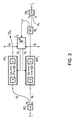
- the optical-connection network comprises two subnetworks 1 and 2.
- the subnetwork 1 (2) comprises an access node 1.1 (2.1), a feed network 1.2 (2.2), and an access network 1.3 (2.3).
- the feed network 1.2 (2.2) in this example consists of an optical-fibre connection 1.5 (2.5), which is coupled to a first end 1.6 (2.6) having the access node 1.1 (2.1), and is connected to a second end 1.7 (2.7) having an access port 1.8 (2.8) of the access network 1.3 (2.3).
- an optical amplifier not shown in the fibre connection 1.5 (2.5).
- the access port 1.8 (2.8) of the access network 1.3 (2.3) is formed by a coupling member consisting of a splitting part 1.10 (2.10) and a switching part 1.11 (2.11).
- the access network 1.3 (2.3) is a tree-shapedly branched passive network for optical-fibre connections to a group G1 (G2) of network connections 1.12 (2.12).
- the group G1 (G2) comprises M subgroups G1.1,--,G1.M (G2.1,--,G2.M) of network connections 1.12 (2.12) to fibre connections of tree-shapedly branched passive network parts 1.13 (2.13), hereinafter called subtrees, of the access network 1.3 (2.3).
- Each subtree 1.13 (2.13) has its own access port, which is formed by a splitting member 1.14 (2.14) having a first input port 1.15 (2.15) and a second input port 1.16 (2.16), and having two or more output ports 1.17 (2.17) by which fibre connections 1.18 (2.18) are coupled to the network connections 1.12 (2.12) of a subgroup in question.
- the splitting part 1.10 (2.10) of the access port 1.8 (2.8) is a passive optical (1:2M) splitter having 2M outputs 1.19 (2.19).
- the switching part 1.11 (2.11) provides for two sets s1 and s2 each having M optical signal switches 1.20 (2.20), hereinafter called switches 1.20 (2.20) for short.
- switches may be combined with amplifiers (not shown).
- the switches are included in the outputs 1.19 (2.19), one per output.
- a first set u 1 of M outputs 1.19 (2.19), in which the switches of the set s1 have already been included, is coupled, by way of optical-fibre connections 1.22 (2.22), to the first input ports 1.15 (2.15) of the M splitting members 1.14 (2.14).
- a second set u 2 of M outputs 1.19 (2.19), in which the switches of the set s2 are included, is coupled, by way of optical-fibre connections 1.23 (2.23) to the second input ports 1.16 (2.16) of the splitting members 2.14 (1.14) of the other subnetwork 2 (1).
- the other subnetwork 2 (1) is in fact extended to a tree-shapedly branched passive optical network having an increased number of network connections, in this case the network connections of both groups G1 and G2.
- the subnetwork 2 (1) therefore continues to be operational, while the group G1 (G2) of network connections becomes accessible by way of a protection path which was formed by switching over the switches 2.20 (1.20) of the second set s2 by way of the access node 2.1 (1.1), the optical-fibre connection 2.5 (1.5), the access port 2.8 (1.8), and the fibre connections 2.23 (1.23) to the second input ports 1.16 (2.16) of the access ports 1.14 (2.14) of the subtrees 1.13 (2.13).
- a main station HS1 and HS2 which transmits the signals to be transported over the subnetworks in the direction of the network connections.
- the two main stations are coupled, possibly by way of other main stations, to make protection possible on the basis of the dual-homing principle.
- the main station HS1 (HS2) in question provides the signal distribution for the subnetwork 1 (2) in question.
- the sets in question of switches s1 and s2 in the access ports 1.8 and 2.8 may be such that the switching over may be done manually as soon as any signal failure is established.
- monotoring and control means which monitor the presence of signal traffic on every fibre connection 1.22 and 2.22 between the access ports 1.8 and 2.8 and the first input ports 1.15 and 2.15 of the access ports 1.14 and 2.14 and, upon detection of the failure of the signal traffic on any of the said connections 1.22 and 2.22, provide the switching over to the protection path in question (see below under the description of FIG. 2).
- the two subnetworks 1 and 2 have a cross bridging by way of the fibre connections 1.23 and 2.23, but for the rest should preferably be fully separated geographically with a view to protection. At any rate, the various sets of switches and the associated control members in the access ports 1.8 and 2.8 should have separate power supplies.
- the set s1 of switches in the access port 1.8 (2.8) may also be replaced by a single switch in the access network 1.2 (2.2) or in the access node 1.1 (2.1).
- the location of the set in the switching part 1.11 (2.11) of the access port 1.8 (2.8) may still offer an additional protection advantage.
- the monitoring and control means are arranged in such a manner that, upon failure in a connection path between the access node and an access port 1.14 (2.14) of a subtree 1.13 (2.13), it may be distinguished whether the failure is, or is not, the result of a failure exclusively in one of the connection paths from the set s1 of switches by way of the fibre connections 1.22 (2.22) up to the access ports 1.14 (2.14).
- the switches of both sets s1 are set at the open position (position st2), and the switches of both sets s2 at the closed position (position st1).
- connection network in which, basically without capacity loss, the signal traffic intended for the group G1 (G2) of network connections of the one subnetwork 1 (2) may be led entirely by way of the access node 2.1 (1.1) and the access network 2.2 (1.2) of the other subnetwork 1 (2).
- the main stations HS1 and HS2 may be distributive stations, such as for CATV [cable television].
- the subnetworks are passive optical networks having unidirectional optical connections, as shown in FIG. 1.
- the optical connections in the subnetworks between the access nodes and the network connections should be bi-directional.
- the fibre connections of each subnetwork are preferably used bi-directionally, with the available switches and amplifiers having to be constructed bi-directionally (see below under the description of FIG. 3).
- FIG. 2 shows a part of the protection configuration of an optical-connection network comprising N ⁇ 2 subnetworks.
- the figure shows only optical terminals F j , F k , and F n for second ends (such as the second ends 1.7 and 2.7 in FIG.
- connection F j constitutes the input to an optical splitter SC j , which is provided with two outputs u 1 and u 2 .
- connection T j constitutes the output of an optical combinator CS j , which is provided with two inputs i 1 and i 2 (corresponding to the inputs 1.15 (2.15) and 1.16 (2.16) in FIG. 1).
- the output u 1 of the splitter SC j and the input i 1 of the combinator CS j are coupled by way of an operational optical connection w j , in which there is included an optical switch WS j .
- the output u 2 of the splitter SC j and the input i 2 of the combinator CS k of the subnetwork k are coupled by way of an optical protection connection p j , in which there is included an optical switch PS j .
- the switches WS j and PS j are, by way of (electrical) drive connections b1 and b2, separately switchable from a control member C j .
- an uncoupling member M j which, by way of an uncoupling output a, supplies a part of the optical-signal power (e.g., 10%) in the operational connection w j to the control member C j .
- the control members C j and C k of the subnetworks j and k which are optically coupled by way of the protection connection p j , are coupled by way of an electrical connection c kj .
- said electrical connection may be constructed either as a direct connection between the consecutive control members, as drawn in the figure, or by way of a central control member.
- the protection configuration of FIG. 2 operates as follows. In the event of undisturbed operation, the switches WS j are in a closed position, as drawn, and continue to be in said position for as long as each control member C j , by way of the uncoupling member M j , detects sufficient signal power in the operational connection w j .
- the control member C k detects too little or no longer any signal power on the operational connection w k by way of the uncoupling member M k , the switch WS k is set at the open position and, by way of the connection c kj and the control member C j , the switch PS j in the corresponding protection connection p j is set at the closed position.
- the group Gk of network connections is again accessible, this time over a protection path which is formed by closing the switch PS j by way of the feed network of the j-th subnetwork and the protection connection p j to the access port connected to the terminal T k of the access network of the k-th subnetwork.
- a protection connection p j (1 ⁇ k ⁇ j ⁇ N)
- the protection connection p k is coupled to the second input i 2 of the combinator CS n , and the control members C k and C n are coupled by way of a connection c nk .
- the protection connection p k is coupled to the second input i 2 of the combinator CS j , and the protection configuration is fully equivalent to that of the exemplary embodiment according to FIG. 1.
- optical splitters SC j and the optical combinators CS j splitters and combinators having three, four etc. outputs and inputs, respectively, and these are coupled to one another in a corresponding manner, apart from over an operational connection, also over two, three etc. protection connections, in such a manner that each splitter is coupled to the combinators of three, four etc. different subnetworks.
- the protection configuration may basically continue to be the same.
- the functions of the splitters SC j and the combinators CS j are inverted when using passive components, so that said components may continue to be unchanged.
- the optical switching means applied whether combined with amplifiers or not, must be suitable for bi-directional operation.
- FIG. 3 there is schematically shown a part of the protection configuration as depicted in FIG. 2, in which the optical switches WS j and PS j are replaced by bi-directional versions, namely, optical switches WS' j and PS' j .
- optical switches applied are preferably combined with optical amplifiers.
- an optical on/off signal switch and an optical amplifier there may be applied, e.g., an erbium-doped fibre amplifier (EDFA).
- EDFA erbium-doped fibre amplifier
- a bi-directional version of such an EDFA applied as switch is disclosed, e.g., in reference [5].
- SCLA semiconductor laser amplifier
Landscapes
- Engineering & Computer Science (AREA)
- Computer Networks & Wireless Communication (AREA)
- Physics & Mathematics (AREA)
- Electromagnetism (AREA)
- Signal Processing (AREA)
- Optical Communication System (AREA)
- Gyroscopes (AREA)
Abstract
Description
- The invention lies in the field of protection systems for networks, such as passive optical networks. More in particular, it relates to a passive optical network having a protection configuration for applying a protection principle based on multiple accessibility, such as the principle of dual homing.
- Developments are increasingly going in a direction of applying passive optical networks (PONs) to the access network, with optical-fibre connections being pulled through to near the subscriber (FTTC [fibre to the curb] or FTTH [fibre to the home]). Configurations for such an access network based on a PON for providing narrow- and wide-band communication between a main station and a large number of linked-up subscribers are known per se, such as, e.g., from reference [1] (see below under C. for more details with respect to the references). Said known network comprises a tree-shaped branching of optical connections, hereinafter called access network, which is provided with a large number (up to approx. 2000) of branchings (or splittings-up) at the subscriber connection side, and a trunk-shaped open feeder, hereinafter called feed network, to an access node of the optical network, where a main station is located. In the access network, the splitting up is effected in two stages, i.e., a first stage (1:16) directly at the connection to the feed network and a second stage (1:128) nearer the subscriber connections. The lengths of the optical connections in the access network are relatively short (< 10 km). The length of the feed network may rather vary (0 - 100 km), depending on the position of the main station. To be capable, at the subscriber connection side, of detecting signals of sufficient strength, signal amplification is required in view of the high degree of splitting-up in the access network, and depending on the length of, in particular, the feed network. Therefore, in the known configuration there are included, at two locations in the optical connections, optical signal amplifiers, namely, a feeder repeater halfway through the feed network and a splitter repeater in the coupling of the feed network to the access network. Such an optical network is vulnerable, however, when optical connections fail, namely, all the more vulnerable in the event of a larger number of connections and a longer feed network. Particularly a fibre or cable breakage in the feed network will have serious consequences. To minimise the consequences of failure of connections in the feed network as a result of cable breakage or equipment failure, the entire network might be duplicated. This is very costly, however, and not strictly necessary. In fact, as a cable breakage or equipment failure in the network occurs at a location closer to the subscriber side, where the access network is further split up, the size of the consequences will decrease. The known technique makes use thereof by applying a protection configuration in which the feed network and the first stage of the access network are duplicated, and the accepted principle of dual homing (see, e.g., reference [2]) is applied, with the redundant feed network leading to a second access node, which offers a second main station access to the network or also offers the same main station a second access to the network. An optical network having such a protection configuration, however, proportionally is still costly, especially in geographical situations in which the probability of failure occurring in the duplicated part of the network, and the redundant part of the network being actually used, is slight.
- In reference [3] there are disclosed self-healing architectures for "fiber-in-the-loop" (FITL) networks having a relatively small number of connections. In a first version, every connection in a distribution area is also accessible from a main station by way of a protection fibre connection which runs through an adjacent distribution area. In a second version, an operational fibre connection in a distribution area is also used as a protection fibre connection for an adjacent distribution area, with a WDM [wavelength division multiplex] technique having a separate wavelength, being applied to the protection signal transport. Said known self-healing architectures are not or hardly suitable for tree-shapedly branched optical networks having large numbers of network connections.
- Reference [4] describes a protection switching system which comprises pairs of (electrical) telecommunication modules for processing or switching telecommunication signals. Each pair comprises an operational module and a standby module. The system further comprises monitoring and switching means for switching over to the standby module upon failure of the corresponding operational module with, as long as the standby module is standby, the latter monitoring the operation of the operational module. The pairs of telecommunication modules may be connected to one another by means of optical-fibre connections. If, according to such a protection technique, an optical network, such as the PON described above, is provided with a protection configuration with, e.g., the feed network and the first stage of the access network forming the duplicated modules, for said optical network there also apply the drawbacks already referred to.
- The object of the invention is to supply a passive optical-connection network provided with a protection configuration for applying a protection principle based on multiple accessibility, such as the principle of dual homing, which does not have the above drawback of the known technique. This is achieved by applying a specific protection coupling between two or more neighbouring similar optical networks which each comprise a feed network and an access network (whether phased or not). Here, the protection coupling is such that corresponding parts, such as the feed network and possibly also a first stage of the access network of a neighbouring similar optical network, may be used multiply in failure situations.
- For this purpose, an optical-connection network according to the preamble of
claim 1, of a type as disclosed in reference [1], according to the invention is characterised as inclaim 1. If the operational connection by way of one of the feed networks actually fails, and is actually switched over by the protection switching means to the protection connection by way of the other feed network, such admittedly involves a loss of capacity per network connection, since in this case both groups of network connections must be served by way of one and the same feed network (in the event of groups with the same numbers of connections, the loss is 50%). Still, all connections continue to be operable, while a duplication of costly network parts may be omitted. Moreover, as long as the protection connection is in use from the main station, which is connected to the access node of the protection connection at a higher network level, the signal transport may be controlled on the basis of priority. Such a control, however, is not part of the present invention. - The protection principle of the invention is more generally applicable as well. For this purpose, an optical-connection network according to the preamble of claim 7, according to the invention is characterised as in claim 7.
- Further embodiments of the optical-connection networks according to the invention are summarised in the subclaims.
-
- [1] I. Van de Voorde and G. Van der Plas, "The evolution of optical access networks towards large split, wide range passive optical networks", 7th IEEE Workshop on optical access networks, 24-28 Sept. 1995, pp. 9.1-1/10;
- [2] T.-H. Wu, "Fiber Network Service Survivability", Artech House, Boston/London, 1992, section 3.2 "Dual-Homing Architectures", pp. 83-85, and section 3.5 "Optical Dual-Homing Architectures", pp. 100-108;
- [3] V.K. Bhagavath et al., "Novel self-healing fiber-in-the-loop architectures", OFC '94 Technical Digest, paper TuE1, pp. 16-18;
- [4] US-A-5,408,462;
- [5] US-A-5,365,368;
- [6] M. Janson, et al., "Monolithically integrated 2x2 InGaAsP/InP laser amplifier gate switch arrays", Electron. Lett., 9th April 1992, Vol. 28, No. 8, pp. 776-778.
- The references referred to above are considered incorporated in the present application.
- The invention will be further explained by means of a description of an exemplary embodiment, with reference being made to a drawing comprising the following figures:
- FIG. 1
- schematically shows a first embodiment of the optical-connection network having a protection configuration according to the invention;
- FIG. 2
- schematically shows a part of the protection configuration of a second embodiment of the optical-connection network according to the invention;
- FIG. 3
- schematically shows a part of the protection configuration for a bi-directional variant of the connection network according to FIG. 2.
- According to a first exemplary embodiment, as schematically shown in FIG. 1, the optical-connection network comprises two
subnetworks - In undisturbed operation, when the two subnetworks are fully operational, the switches 1.20 and 2.20 of the sets s1 in the switching parts 1.11 and 2.11 of the access ports 1.8 and 2.8 of both
subnetworks - To each of the access nodes 1.1 and 2.1 of the
subnetworks subnetwork 2. The sets in question of switches s1 and s2 in the access ports 1.8 and 2.8 may be such that the switching over may be done manually as soon as any signal failure is established. Preferably, however, to each access port 1.8 and 2.8 there are added monotoring and control means, which monitor the presence of signal traffic on every fibre connection 1.22 and 2.22 between the access ports 1.8 and 2.8 and the first input ports 1.15 and 2.15 of the access ports 1.14 and 2.14 and, upon detection of the failure of the signal traffic on any of the said connections 1.22 and 2.22, provide the switching over to the protection path in question (see below under the description of FIG. 2). - The two
subnetworks - Basically, the set s1 of switches in the access port 1.8 (2.8) may also be replaced by a single switch in the access network 1.2 (2.2) or in the access node 1.1 (2.1). The location of the set in the switching part 1.11 (2.11) of the access port 1.8 (2.8) may still offer an additional protection advantage. For this purpose, in a variant of the optical-connection network, the monitoring and control means are arranged in such a manner that, upon failure in a connection path between the access node and an access port 1.14 (2.14) of a subtree 1.13 (2.13), it may be distinguished whether the failure is, or is not, the result of a failure exclusively in one of the connection paths from the set s1 of switches by way of the fibre connections 1.22 (2.22) up to the access ports 1.14 (2.14). Upon the occurrence of such a failure, the switches of both sets s1 are set at the open position (position st2), and the switches of both sets s2 at the closed position (position st1). As a result, there is created a connection network in which, basically without capacity loss, the signal traffic intended for the group G1 (G2) of network connections of the one subnetwork 1 (2) may be led entirely by way of the access node 2.1 (1.1) and the access network 2.2 (1.2) of the other subnetwork 1 (2). The greater the geographical distance between the access ports 1.8 (2.8) and 1.14 (2.14), the greater the importance of said variant.
- The main stations HS1 and HS2 may be distributive stations, such as for CATV [cable television]. In this case, the subnetworks are passive optical networks having unidirectional optical connections, as shown in FIG. 1. In the event that the main stations are telecommunication exchanges for providing bi-directional communication, such as telephony and various wide-band services, the optical connections in the subnetworks between the access nodes and the network connections should be bi-directional. For this purpose, there may be present, for each subnetwork, an identical overlay network having the corresponding switches and amplifiers orientated in opposite directions, which is of course a costly embodiment. The fibre connections of each subnetwork are preferably used bi-directionally, with the available switches and amplifiers having to be constructed bi-directionally (see below under the description of FIG. 3).
- The principle of the protection configuration described with reference to FIG. 1 is also applicable to optical-connection networks comprising more than two subnetworks. Such an optical-connection network is described using FIG. 2. The figure shows a part of the protection configuration of an optical-connection network comprising N≥2 subnetworks. With a view to simplicity, for three subnetworks j, k and n (where j≠k, j≠n and 1≤j,k,n≤N) the figure shows only optical terminals Fj, Fk, and Fn for second ends (such as the second ends 1.7 and 2.7 in FIG. 1) of the feed networks of the subnetworks j, k and n, and optical terminals Tj, Tk and Tn for the terminals of the access networks (such as the subtrees 1.13 and 2.13 of FIG. 1) of the subnetworks j, k and n. The following, which is described for the j-th subnetwork, is applicable, mutatis mutandis, to the corresponding components of the k-th and the n-th subnetwork. The connection Fj constitutes the input to an optical splitter SCj, which is provided with two outputs u1 and u2. The connection Tj constitutes the output of an optical combinator CSj, which is provided with two inputs i1 and i2 (corresponding to the inputs 1.15 (2.15) and 1.16 (2.16) in FIG. 1). The output u1 of the splitter SCj and the input i1 of the combinator CSj are coupled by way of an operational optical connection wj, in which there is included an optical switch WSj. The output u2 of the splitter SCj and the input i2 of the combinator CSk of the subnetwork k are coupled by way of an optical protection connection pj, in which there is included an optical switch PSj. The switches WSj and PSj are, by way of (electrical) drive connections b1 and b2, separately switchable from a control member Cj. In the operational connection wj there is also included an uncoupling member Mj which, by way of an uncoupling output a, supplies a part of the optical-signal power (e.g., 10%) in the operational connection wj to the control member Cj. The control members Cj and Ck of the subnetworks j and k, which are optically coupled by way of the protection connection pj, are coupled by way of an electrical connection ckj. Depending on the construction of the setup chosen for the control, said electrical connection may be constructed either as a direct connection between the consecutive control members, as drawn in the figure, or by way of a central control member.
- The protection configuration of FIG. 2 operates as follows. In the event of undisturbed operation, the switches WSj are in a closed position, as drawn, and continue to be in said position for as long as each control member Cj, by way of the uncoupling member Mj, detects sufficient signal power in the operational connection wj. If, in one of the subnetworks, e.g., the k-th subnetwork, the control member Ck detects too little or no longer any signal power on the operational connection wk by way of the uncoupling member Mk, the switch WSk is set at the open position and, by way of the connection ckj and the control member Cj, the switch PSj in the corresponding protection connection pj is set at the closed position. In this manner, the group Gk of network connections is again accessible, this time over a protection path which is formed by closing the switch PSj by way of the feed network of the j-th subnetwork and the protection connection pj to the access port connected to the terminal Tk of the access network of the k-th subnetwork. In said protection configuration, with each operational connection wk there is associated a protection connection pj (1≤k≠j≤N), so that the principle of dual homing for each group Gk continues to be fully applicable. In an embodiment of said protection configuration for N=3 subnetworks, the protection connection pk is coupled to the second input i2 of the combinator CSn, and the control members Ck and Cn are coupled by way of a connection cnk. For N=2 subnetworks, the protection connection pk is coupled to the second input i2 of the combinator CSj, and the protection configuration is fully equivalent to that of the exemplary embodiment according to FIG. 1.
- For the protection configuration according to FIG. 2, too, a variant is possible in which, in the event of a failure as a result of a failure established in one of the operational connections wj, there is set up, by opening all switches WSj and closing all switches PSj, a connection network in which all groups of network connections are again fully accessible, albeit all of them by way of the main station to which the group in question has been allocated for applying the principle of dual homing.
- Should the number of subnetworks be three, four or more, it is possible to simply extend the described protection principle, if necessary, to a threefold, fourfold etc., accessibility. To that end there are chosen, for the optical splitters SCj and the optical combinators CSj, splitters and combinators having three, four etc. outputs and inputs, respectively, and these are coupled to one another in a corresponding manner, apart from over an operational connection, also over two, three etc. protection connections, in such a manner that each splitter is coupled to the combinators of three, four etc. different subnetworks.
- For a bi-directional optical-connection network in which the fibre connections are used bi-directionally, the protection configuration may basically continue to be the same. In the return-signal direction, the functions of the splitters SCj and the combinators CSj are inverted when using passive components, so that said components may continue to be unchanged. In this case, however, the optical switching means applied, whether combined with amplifiers or not, must be suitable for bi-directional operation. In FIG. 3, there is schematically shown a part of the protection configuration as depicted in FIG. 2, in which the optical switches WSj and PSj are replaced by bi-directional versions, namely, optical switches WS'j and PS'j.
- The described protection configurations are of particular advantage in tree-shapedly branched optical networks having large numbers of network connections, and therefore having a high degree of splitting. Therefore, the optical switches applied are preferably combined with optical amplifiers. As such a combination of an optical on/off signal switch and an optical amplifier, there may be applied, e.g., an erbium-doped fibre amplifier (EDFA). A bi-directional version of such an EDFA applied as switch is disclosed, e.g., in reference [5]. As integrated embodiment for such an optical switch/amplifier, there may be applied, e.g., a semiconductor laser amplifier (SCLA), as described in reference [6].
Claims (11)
- Optical-connection network having a protection configuration for applying a protection principle based on dual accessibility, such as the dual-homing principle, comprising:a first and a second access node,a first group of optical network connections,a first passive tree-shapedly branched access network of optical connections between an access port of the access network and the first group of optical network connections,a first feed network provided with a first end coupled to the first access node, and with a second end coupled to the optical access port of the first access network, anda second feed network provided with a first end coupled to the second access node, and with a second end coupled to the optical access port of the first access network,
with the first feed network providing for a first operational connection to the optical access port of the first access network, and the second feed network providing for a first protection connection to the optical access port of the access network for use upon failure of the first operational connection,
characterised in that the optical-connection network further comprises:first protection switching means for switching over the first operational connection to the first protection connection upon failure of the first operational connection,a second group of optical network connections, anda second passive tree-shapedly branched access network of optical connections between an access port of the second access network and the second group of optical network connections, and that the second end of the second feed network is also coupled to the access port of the second access network, with the second feed network providing for a second operational connection for the second access network. - Optical-connection network according to claim 1, characterised in that the second end of the first feed network is also coupled to the access port of the second access network and at the same time provides for a second protection connection for the second access network, and
that the optical-connection network further comprises second protection switching means for switching over the second operational connection to the second protection connection upon failure of the second operational connection. - Optical-connection network according to claim 2, characterised in that the first protection switching means comprise:a first optical switching member included in the coupling of the second end of the second feed network to the access port of the second access network, for switching the second operational connection on/off, anda second optical switching member included in the coupling of the second end of the second feed network to the access port of the first access network for switching the first protection connection on/off, and
that the second protection switching means comprise:a third optical switching member included in the coupling of the second end of the first feed network to the access port of the first access network for switching first operational connection on/off, anda fourth optical switching member included in the coupling of the second end of the first feed network to the access port of the second access network for switching the second protection connection on/off,
with, for using the first protection connection, the second switching member and the third switching member being on and off, respectively, and, for using the second protection connection, the fourth switching member and the first switching member being on and off, respectively. - Optical-connection network according to claim 3, characterised in that at least one of the access networks comprises a number (M≥1) of tree-shapedly branched connection parts, with each connection part being provided with a separate access port, with the second end of both the first and the second feed network by way of optical splitting members having separate couplings to the separate access ports of the connection parts, and with the switching members in question comprising a number of optical switches corresponding to the number of connection parts, one in each separate coupling.
- Optical-connection network according to claim 4, characterised in that at least one of the switches is constructed as an on/off-switchable signal amplifier.
- Optical-connection network according to claim 4, characterised in that the optical connections in the network are bi-directional connections, and that at least one of the optical switches is constructed as a bi-directional on/off-switchable signal amplifier.
- Optical-connection network having a protection configuration for applying a protection principle based on multiple accessibility, such as the dual-homing principle, comprising a number (N≥2) of access nodes, a corresponding number of groups of optical network connections, and a corresponding number of separate subnetworks, with a j-th subnetwork (for each j = 1,--,N) comprising:- a passive tree-shapedly branched access network of optical connections between an optical access port of the access network and a j-th group of optical network connections, and- a feed network provided with a first end coupled to the j-th access node and with a second end coupled to the optical access port of the access network, which feed network provides for an operational connection of the j-th access node to the optical access port of the access network,
characterised in that the second end of the feed network of a j-th subnetwork is at the same time coupled to an optical access port of the access network of a k-th subnetwork (k ≠ j), with the feed network of the j-th subnetwork providing for a protection connection for the k-th subnetwork for use upon failure of the operational connection of the k-th subnetwork, and
that the j-th subnetwork further comprises protection switching means for switching over upon failure of the operational connection of the k-th subnetwork to the protection connection by way of the feed network of the j-th subnetwork. - Optical-connection network according to claim 7, characterised in that the protection switching means of each j-th subnetwork (for j = 1,--,N) comprise:- a first optical switching member included in the coupling of the second end of the feed network to the access port of the access network, for switching the operational connection of the j-th subnetwork on/off,- a second optical switching member included in the coupling of the second end of the feed network to the access port of the access network of the k-th subnetwork, for switching the protection connection for the k-th subnetwork on/off, and- a control member for separately controlling the first and second optical switching members, and
in that the control member of the j-th subnetwork is coupled to the control member of the k-th subnetwork,
with, for using the protection connection by way of the feed network of the j-th subnetwork, the second optical switching member of the j-th subnetwork being on, and the first optical switching member of the k-th subnetwork being off. - Optical-connection network according to claim 8, characterised in that at least the access network of the k-th subnetwork comprises a number (M≥1) of tree-shapedly branched connection parts, each connection part provided with a separate access port, with the second end of both the first and the second feed network having, by way of optical splitting members, separate couplings to the separate access ports of the connection parts, and with the switching members in question including a number of optical switches corresponding to the number of connection parts, one in each separate coupling.
- Optical-connection network according to claim 9, characterised in that at least one of the optical switches is constructed as an on/off-switchable optical signal amplifier.
- Optical-connection network according to claim 9, characterised in that the optical connections in the network are bi-directional connections, and
that at least one of the optical switches is constructed as a bi-directional on/off-switchable optical signal amplifier.
Applications Claiming Priority (2)
| Application Number | Priority Date | Filing Date | Title |
|---|---|---|---|
| NL1002940A NL1002940C2 (en) | 1996-04-24 | 1996-04-24 | Optical network with protection configuration. |
| NL1002940 | 1996-04-24 |
Publications (2)
| Publication Number | Publication Date |
|---|---|
| EP0803996A1 true EP0803996A1 (en) | 1997-10-29 |
| EP0803996B1 EP0803996B1 (en) | 2004-12-15 |
Family
ID=19762726
Family Applications (1)
| Application Number | Title | Priority Date | Filing Date |
|---|---|---|---|
| EP97200878A Expired - Lifetime EP0803996B1 (en) | 1996-04-24 | 1997-03-24 | Optical network having protection configuration |
Country Status (5)
| Country | Link |
|---|---|
| US (1) | US5896474A (en) |
| EP (1) | EP0803996B1 (en) |
| AT (1) | ATE285143T1 (en) |
| DE (1) | DE69731910T2 (en) |
| NL (1) | NL1002940C2 (en) |
Cited By (3)
| Publication number | Priority date | Publication date | Assignee | Title |
|---|---|---|---|---|
| WO2001056203A2 (en) * | 2000-01-28 | 2001-08-02 | Telefonaktiebolaget Lm Ericsson (Publ) | Cross-connect protection |
| EP1784045A1 (en) * | 2005-11-03 | 2007-05-09 | Alcatel Lucent | System and method for fast layer 2 protection in passive optical networks |
| WO2010112845A1 (en) * | 2009-03-31 | 2010-10-07 | British Telecommunications | Optical fibre network |
Families Citing this family (21)
| Publication number | Priority date | Publication date | Assignee | Title |
|---|---|---|---|---|
| NO970466L (en) * | 1997-02-03 | 1998-08-04 | Ericsson Telefon Ab L M | Method and system for protecting equipment and switching functionality in a telecommunications system |
| US6427035B1 (en) * | 1999-08-12 | 2002-07-30 | Bellsouth Intellectual Property Corporation | Method and apparatus for deploying fiber optic cable to subscriber |
| US6498667B1 (en) | 1999-09-10 | 2002-12-24 | Quantum Bridge Communications, Inc. | Method and system for packet transmission over passive optical network |
| US6122335A (en) * | 1999-10-01 | 2000-09-19 | Quantum Bridge Communications, Inc. | Method and apparatus for fast burst mode data recovery |
| US6592272B1 (en) | 1999-10-22 | 2003-07-15 | Quantum Bridge Communications, Inc. | Burst mode transmission over multiple optical wavelengths |
| US6587235B1 (en) * | 1999-12-16 | 2003-07-01 | At&T Corp. | Method and apparatus for capacity-efficient restoration in an optical communication system |
| US6813241B1 (en) * | 1999-12-18 | 2004-11-02 | Nortel Networks Limited | Network architecture and method of providing link protection in a bidirectional data traffic network |
| US6990123B1 (en) | 2000-01-24 | 2006-01-24 | Quantum Bridge Communications Inc. | Method and apparatus for redundant transmission over TDMA optical networks |
| US20020145775A1 (en) * | 2001-04-06 | 2002-10-10 | Quantum Bridge Communications, Inc. | TDM/WDMA passive optical network |
| US6307986B1 (en) | 2001-04-24 | 2001-10-23 | Seneca Networks | Protection switching in bidirectional WDM optical communication networks with transponders |
| US6321004B1 (en) | 2001-04-24 | 2001-11-20 | Seneca Networks | Protection switching in bidirectional WDM optical communication networks |
| US20040105136A1 (en) * | 2001-05-08 | 2004-06-03 | Corvis Corporation | Interconnections and protection between optical communications networks |
| US6563979B2 (en) * | 2001-06-22 | 2003-05-13 | Dorsal Networks, Inc. | Automatically switched redundant switch configurations |
| US7254330B2 (en) * | 2001-07-20 | 2007-08-07 | Tellabs Bedford, Inc. | Single fiber passive optical network wavelength division multiplex overlay |
| US7289428B2 (en) * | 2001-08-13 | 2007-10-30 | Tellabs Operations, Inc. | Inter-working mesh telecommunications networks |
| US20080002669A1 (en) * | 2001-09-14 | 2008-01-03 | O'brien Ray | Packet voice gateway |
| US7283745B2 (en) * | 2003-03-31 | 2007-10-16 | Lucent Technologies Inc. | Methods and apparatus for constructing switch arrays for routing of optical signals so as to minimize power dissipation |
| US7050668B2 (en) * | 2003-06-19 | 2006-05-23 | Lucent Technologies Inc. | Methods and apparatus for control of optical switching arrays that minimize bright state switching |
| TWI248263B (en) * | 2004-05-10 | 2006-01-21 | Ind Tech Res Inst | Passive optical network with protection mechanism and its method of relocation |
| US7532817B1 (en) | 2004-06-29 | 2009-05-12 | Lightech Fiberoptics, Inc. | Fiber optic link protection apparatus |
| TW200827797A (en) * | 2006-12-20 | 2008-07-01 | Inventec Multimedia & Telecom | Switching device of light-beam channel of optical fiber network |
Citations (2)
| Publication number | Priority date | Publication date | Assignee | Title |
|---|---|---|---|---|
| DE4306032A1 (en) * | 1993-02-26 | 1994-09-01 | Siemens Ag | Circuit arrangement for electro-optical changeover to standby during operation in communications systems |
| WO1995010146A1 (en) * | 1993-10-07 | 1995-04-13 | Adc Telecommunications, Inc. | Protection switching apparatus and method |
Family Cites Families (5)
| Publication number | Priority date | Publication date | Assignee | Title |
|---|---|---|---|---|
| US5740157A (en) * | 1992-05-21 | 1998-04-14 | Alcatel Network Systems, Inc. | Distributed control methodology and mechanism for implementing automatic protection switching |
| US5317439A (en) * | 1992-07-17 | 1994-05-31 | At&T Bell Laboratories | Automatic on-line monitoring and optimization of optical network switching nodes |
| IL106766A (en) * | 1992-08-28 | 1995-12-31 | Hughes Aircraft Co | Bi-directional optical fiber amplifier for missile guidance data link repeater |
| US5539564A (en) * | 1993-09-22 | 1996-07-23 | Nippon Telegraph And Telephone Corporation | Point-to-multipoint optical transmission system |
| US5524154A (en) * | 1994-08-31 | 1996-06-04 | At&T Corp. | Hybrid architecture for an optical switching fabric implemented with 1×2 switching devices |
-
1996
- 1996-04-24 NL NL1002940A patent/NL1002940C2/en not_active IP Right Cessation
-
1997
- 1997-03-24 EP EP97200878A patent/EP0803996B1/en not_active Expired - Lifetime
- 1997-03-24 DE DE69731910T patent/DE69731910T2/en not_active Expired - Lifetime
- 1997-03-24 AT AT97200878T patent/ATE285143T1/en not_active IP Right Cessation
- 1997-04-02 US US08/840,547 patent/US5896474A/en not_active Expired - Fee Related
Patent Citations (2)
| Publication number | Priority date | Publication date | Assignee | Title |
|---|---|---|---|---|
| DE4306032A1 (en) * | 1993-02-26 | 1994-09-01 | Siemens Ag | Circuit arrangement for electro-optical changeover to standby during operation in communications systems |
| WO1995010146A1 (en) * | 1993-10-07 | 1995-04-13 | Adc Telecommunications, Inc. | Protection switching apparatus and method |
Non-Patent Citations (2)
| Title |
|---|
| GERLA M ET AL: "FAULT TOLERANT PON TOPOLOGIES", ONE WORLD THROUGH COMMUNICATIONS, FLORENCE, MAY 4 - 8, 1992, vol. 1 OF 3, 1 January 1992 (1992-01-01), INSTITUTE OF ELECTRICAL AND ELECTRONICS ENGINEERS, pages 49 - 56, XP000300045 * |
| TSONG-HO WU: "A NOVEL ARCHITECTURE FOR OPTICAL DUAL HOMING SURVIVABLE FIBER NETWORKS", INTERNATIONAL CONFERENCE ON COMMUNICATIONS, INCLUDING SUPERCOMM TECHNICAL SESSIONS. ATLANTA, APR. 15 - 19, 1990, vol. 2 OF 4, 15 April 1990 (1990-04-15), INSTITUTE OF ELECTRICAL AND ELECTRONICS ENGINEERS, pages 533 - 539, XP000146120 * |
Cited By (5)
| Publication number | Priority date | Publication date | Assignee | Title |
|---|---|---|---|---|
| WO2001056203A2 (en) * | 2000-01-28 | 2001-08-02 | Telefonaktiebolaget Lm Ericsson (Publ) | Cross-connect protection |
| WO2001056203A3 (en) * | 2000-01-28 | 2002-01-03 | Ericsson Telefon Ab L M | Cross-connect protection |
| EP1784045A1 (en) * | 2005-11-03 | 2007-05-09 | Alcatel Lucent | System and method for fast layer 2 protection in passive optical networks |
| US7756018B2 (en) | 2005-11-03 | 2010-07-13 | Alcatel Lucent | System and method for implementing fast layer 2 protection in passive optical networks |
| WO2010112845A1 (en) * | 2009-03-31 | 2010-10-07 | British Telecommunications | Optical fibre network |
Also Published As
| Publication number | Publication date |
|---|---|
| US5896474A (en) | 1999-04-20 |
| ATE285143T1 (en) | 2005-01-15 |
| NL1002940C2 (en) | 1997-10-28 |
| DE69731910T2 (en) | 2005-12-29 |
| DE69731910D1 (en) | 2005-01-20 |
| EP0803996B1 (en) | 2004-12-15 |
Similar Documents
| Publication | Publication Date | Title |
|---|---|---|
| EP0803996B1 (en) | Optical network having protection configuration | |
| US6351582B1 (en) | Passive optical network arrangement | |
| US6587235B1 (en) | Method and apparatus for capacity-efficient restoration in an optical communication system | |
| US7634160B2 (en) | Passive optical network system based on a wavelength protection and protecting backup method thereof | |
| US7272321B1 (en) | Passive optical network | |
| US7499647B2 (en) | Fully protected broadcast and select all optical network | |
| US6046833A (en) | Method and apparatus for operation, protection, and restoration of heterogeneous optical communication networks | |
| US5181134A (en) | Photonic cross-connect switch | |
| US6542268B1 (en) | Optical channel cross connect for telecommunication systems in wdm technology (wavelength division multiplexing) having a double spatial switching structure of optical flows strictly not blocking and interposed functional units operating on single channels | |
| US20070201873A1 (en) | Wavelength Division Multiplexed (WDM) Ring Passive Optical Network (PON) with Route Protection for Replacement of Splitter Based Passive Optical Networks | |
| USH2075H1 (en) | Restorable architectures for fiber-based broadband local access networks | |
| KR100955129B1 (en) | wavelength-division multiple access passive optical network using the incoherent broadband light source | |
| US20070280690A1 (en) | System and Method for Managing Power in an Optical Network | |
| CN101040472A (en) | System and apparatus for a carrier class WDM pon providing trunk protection with increased fiber utilization, distance and bandwidth | |
| US6839514B1 (en) | Method and apparatus for operation, protection, and restoration of heterogeneous optical communication networks | |
| KR100411531B1 (en) | Power splitter for optical networks | |
| KR20030083742A (en) | Method and apparatus for transferring wdm signals between different wdm communications systems in optically transparent manner | |
| US20080138063A1 (en) | System and Method for Protecting an Optical Network | |
| EP1064739B1 (en) | Protection of wdm-channels | |
| US6061482A (en) | Channel layered optical cross-connect restoration system | |
| US7302180B2 (en) | Dual homing for DWDM networks in fiber rings | |
| KR100356019B1 (en) | Optical Distribution Network in ATM-PON System | |
| US5930017A (en) | Method and system for maintaining an optical path | |
| Wagner et al. | Multiwavelength ring networks for switch consolidation and interconnection | |
| US20050036444A1 (en) | WDM bidirectional add/drop self-healing hubbed ring network |
Legal Events
| Date | Code | Title | Description |
|---|---|---|---|
| PUAI | Public reference made under article 153(3) epc to a published international application that has entered the european phase |
Free format text: ORIGINAL CODE: 0009012 |
|
| AK | Designated contracting states |
Kind code of ref document: A1 Designated state(s): AT BE CH DE DK ES FI FR GB GR IE IT LI LU NL PT SE |
|
| 17P | Request for examination filed |
Effective date: 19980429 |
|
| RAP3 | Party data changed (applicant data changed or rights of an application transferred) |
Owner name: KONINKLIJKE KPN N.V. |
|
| 17Q | First examination report despatched |
Effective date: 20030404 |
|
| GRAP | Despatch of communication of intention to grant a patent |
Free format text: ORIGINAL CODE: EPIDOSNIGR1 |
|
| GRAS | Grant fee paid |
Free format text: ORIGINAL CODE: EPIDOSNIGR3 |
|
| GRAA | (expected) grant |
Free format text: ORIGINAL CODE: 0009210 |
|
| AK | Designated contracting states |
Kind code of ref document: B1 Designated state(s): AT BE CH DE DK ES FI FR GB GR IE IT LI LU NL PT SE |
|
| PG25 | Lapsed in a contracting state [announced via postgrant information from national office to epo] |
Ref country code: FI Free format text: LAPSE BECAUSE OF FAILURE TO SUBMIT A TRANSLATION OF THE DESCRIPTION OR TO PAY THE FEE WITHIN THE PRESCRIBED TIME-LIMIT Effective date: 20041215 Ref country code: AT Free format text: LAPSE BECAUSE OF FAILURE TO SUBMIT A TRANSLATION OF THE DESCRIPTION OR TO PAY THE FEE WITHIN THE PRESCRIBED TIME-LIMIT Effective date: 20041215 |
|
| REG | Reference to a national code |
Ref country code: CH Ref legal event code: NV Representative=s name: ISLER & PEDRAZZINI AG Ref country code: GB Ref legal event code: FG4D Ref country code: CH Ref legal event code: EP |
|
| REG | Reference to a national code |
Ref country code: IE Ref legal event code: FG4D |
|
| REF | Corresponds to: |
Ref document number: 69731910 Country of ref document: DE Date of ref document: 20050120 Kind code of ref document: P |
|
| PG25 | Lapsed in a contracting state [announced via postgrant information from national office to epo] |
Ref country code: SE Free format text: LAPSE BECAUSE OF FAILURE TO SUBMIT A TRANSLATION OF THE DESCRIPTION OR TO PAY THE FEE WITHIN THE PRESCRIBED TIME-LIMIT Effective date: 20050315 Ref country code: GR Free format text: LAPSE BECAUSE OF FAILURE TO SUBMIT A TRANSLATION OF THE DESCRIPTION OR TO PAY THE FEE WITHIN THE PRESCRIBED TIME-LIMIT Effective date: 20050315 Ref country code: DK Free format text: LAPSE BECAUSE OF FAILURE TO SUBMIT A TRANSLATION OF THE DESCRIPTION OR TO PAY THE FEE WITHIN THE PRESCRIBED TIME-LIMIT Effective date: 20050315 |
|
| PG25 | Lapsed in a contracting state [announced via postgrant information from national office to epo] |
Ref country code: IE Free format text: LAPSE BECAUSE OF NON-PAYMENT OF DUE FEES Effective date: 20050324 |
|
| PG25 | Lapsed in a contracting state [announced via postgrant information from national office to epo] |
Ref country code: ES Free format text: LAPSE BECAUSE OF FAILURE TO SUBMIT A TRANSLATION OF THE DESCRIPTION OR TO PAY THE FEE WITHIN THE PRESCRIBED TIME-LIMIT Effective date: 20050326 |
|
| PLBE | No opposition filed within time limit |
Free format text: ORIGINAL CODE: 0009261 |
|
| STAA | Information on the status of an ep patent application or granted ep patent |
Free format text: STATUS: NO OPPOSITION FILED WITHIN TIME LIMIT |
|
| ET | Fr: translation filed | ||
| 26N | No opposition filed |
Effective date: 20050916 |
|
| REG | Reference to a national code |
Ref country code: IE Ref legal event code: MM4A |
|
| PGFP | Annual fee paid to national office [announced via postgrant information from national office to epo] |
Ref country code: LU Payment date: 20060314 Year of fee payment: 10 |
|
| REG | Reference to a national code |
Ref country code: CH Ref legal event code: PCAR Free format text: ISLER & PEDRAZZINI AG;POSTFACH 1772;8027 ZUERICH (CH) |
|
| PG25 | Lapsed in a contracting state [announced via postgrant information from national office to epo] |
Ref country code: PT Free format text: LAPSE BECAUSE OF NON-PAYMENT OF DUE FEES Effective date: 20050515 |
|
| PGFP | Annual fee paid to national office [announced via postgrant information from national office to epo] |
Ref country code: BE Payment date: 20070419 Year of fee payment: 11 |
|
| BERE | Be: lapsed |
Owner name: KONINKLIJKE *KPN N.V. Effective date: 20080331 |
|
| PG25 | Lapsed in a contracting state [announced via postgrant information from national office to epo] |
Ref country code: BE Free format text: LAPSE BECAUSE OF NON-PAYMENT OF DUE FEES Effective date: 20080331 |
|
| PG25 | Lapsed in a contracting state [announced via postgrant information from national office to epo] |
Ref country code: LU Free format text: LAPSE BECAUSE OF NON-PAYMENT OF DUE FEES Effective date: 20070324 |
|
| REG | Reference to a national code |
Ref country code: CH Ref legal event code: PUE Owner name: AMSTR. INVESTMENTS 23 K.G., LLC Free format text: KONINKLIJKE KPN N.V.#STATIONSPLEIN 7#9726 AE GRONINGEN (NL) -TRANSFER TO- AMSTR. INVESTMENTS 23 K.G., LLC#2711 CENTERVILLE RD., SUITE 400#WILMINGTON DE 19808 (US) |
|
| PGFP | Annual fee paid to national office [announced via postgrant information from national office to epo] |
Ref country code: CH Payment date: 20100325 Year of fee payment: 14 |
|
| PGFP | Annual fee paid to national office [announced via postgrant information from national office to epo] |
Ref country code: IT Payment date: 20100324 Year of fee payment: 14 |
|
| REG | Reference to a national code |
Ref country code: FR Ref legal event code: TP |
|
| REG | Reference to a national code |
Ref country code: NL Ref legal event code: SD Effective date: 20100602 |
|
| REG | Reference to a national code |
Ref country code: GB Ref legal event code: 732E Free format text: REGISTERED BETWEEN 20100617 AND 20100623 |
|
| PGFP | Annual fee paid to national office [announced via postgrant information from national office to epo] |
Ref country code: NL Payment date: 20100315 Year of fee payment: 14 |
|
| REG | Reference to a national code |
Ref country code: NL Ref legal event code: V1 Effective date: 20111001 |
|
| REG | Reference to a national code |
Ref country code: CH Ref legal event code: PL |
|
| PG25 | Lapsed in a contracting state [announced via postgrant information from national office to epo] |
Ref country code: LI Free format text: LAPSE BECAUSE OF NON-PAYMENT OF DUE FEES Effective date: 20110331 Ref country code: CH Free format text: LAPSE BECAUSE OF NON-PAYMENT OF DUE FEES Effective date: 20110331 Ref country code: NL Free format text: LAPSE BECAUSE OF NON-PAYMENT OF DUE FEES Effective date: 20111001 |
|
| PG25 | Lapsed in a contracting state [announced via postgrant information from national office to epo] |
Ref country code: IT Free format text: LAPSE BECAUSE OF NON-PAYMENT OF DUE FEES Effective date: 20110324 |
|
| REG | Reference to a national code |
Ref country code: FR Ref legal event code: PLFP Year of fee payment: 20 |
|
| PGFP | Annual fee paid to national office [announced via postgrant information from national office to epo] |
Ref country code: FR Payment date: 20160223 Year of fee payment: 20 Ref country code: GB Payment date: 20160224 Year of fee payment: 20 |
|
| PGFP | Annual fee paid to national office [announced via postgrant information from national office to epo] |
Ref country code: DE Payment date: 20160324 Year of fee payment: 20 |
|
| REG | Reference to a national code |
Ref country code: DE Ref legal event code: R071 Ref document number: 69731910 Country of ref document: DE |
|
| REG | Reference to a national code |
Ref country code: GB Ref legal event code: PE20 Expiry date: 20170323 |
|
| PG25 | Lapsed in a contracting state [announced via postgrant information from national office to epo] |
Ref country code: GB Free format text: LAPSE BECAUSE OF EXPIRATION OF PROTECTION Effective date: 20170323 |
|
| REG | Reference to a national code |
Ref country code: DE Ref legal event code: R082 Ref document number: 69731910 Country of ref document: DE Representative=s name: SCHOEN, THILO, DIPL.-PHYS., DE |