EP0801496A2 - Color image pickup apparatus - Google Patents
Color image pickup apparatus Download PDFInfo
- Publication number
- EP0801496A2 EP0801496A2 EP97302473A EP97302473A EP0801496A2 EP 0801496 A2 EP0801496 A2 EP 0801496A2 EP 97302473 A EP97302473 A EP 97302473A EP 97302473 A EP97302473 A EP 97302473A EP 0801496 A2 EP0801496 A2 EP 0801496A2
- Authority
- EP
- European Patent Office
- Prior art keywords
- level
- image pickup
- area
- iris
- luminance
- Prior art date
- Legal status (The legal status is an assumption and is not a legal conclusion. Google has not performed a legal analysis and makes no representation as to the accuracy of the status listed.)
- Granted
Links
- 238000001514 detection method Methods 0.000 claims 2
- 238000012935 Averaging Methods 0.000 claims 1
- 238000003384 imaging method Methods 0.000 abstract description 44
- 230000001276 controlling effect Effects 0.000 description 14
- 230000000875 corresponding effect Effects 0.000 description 5
- 101000687727 Homo sapiens Transcriptional regulator PINT87aa Proteins 0.000 description 4
- 102100024797 Transcriptional regulator PINT87aa Human genes 0.000 description 4
- 238000000034 method Methods 0.000 description 3
- 238000010586 diagram Methods 0.000 description 2
- 230000000694 effects Effects 0.000 description 2
- 238000005070 sampling Methods 0.000 description 2
- 230000002411 adverse Effects 0.000 description 1
- 230000002596 correlated effect Effects 0.000 description 1
- 238000005286 illumination Methods 0.000 description 1
- 230000009545 invasion Effects 0.000 description 1
- 210000003127 knee Anatomy 0.000 description 1
- 239000011159 matrix material Substances 0.000 description 1
- NJPPVKZQTLUDBO-UHFFFAOYSA-N novaluron Chemical compound C1=C(Cl)C(OC(F)(F)C(OC(F)(F)F)F)=CC=C1NC(=O)NC(=O)C1=C(F)C=CC=C1F NJPPVKZQTLUDBO-UHFFFAOYSA-N 0.000 description 1
- 102000030592 phosphoserine aminotransferase Human genes 0.000 description 1
- 108010088694 phosphoserine aminotransferase Proteins 0.000 description 1
- 230000001360 synchronised effect Effects 0.000 description 1
Images


Classifications
-
- H—ELECTRICITY
- H04—ELECTRIC COMMUNICATION TECHNIQUE
- H04N—PICTORIAL COMMUNICATION, e.g. TELEVISION
- H04N23/00—Cameras or camera modules comprising electronic image sensors; Control thereof
- H04N23/70—Circuitry for compensating brightness variation in the scene
- H04N23/71—Circuitry for evaluating the brightness variation
-
- H—ELECTRICITY
- H04—ELECTRIC COMMUNICATION TECHNIQUE
- H04N—PICTORIAL COMMUNICATION, e.g. TELEVISION
- H04N23/00—Cameras or camera modules comprising electronic image sensors; Control thereof
- H04N23/70—Circuitry for compensating brightness variation in the scene
- H04N23/75—Circuitry for compensating brightness variation in the scene by influencing optical camera components
-
- H—ELECTRICITY
- H01—ELECTRIC ELEMENTS
- H01L—SEMICONDUCTOR DEVICES NOT COVERED BY CLASS H10
- H01L27/00—Devices consisting of a plurality of semiconductor or other solid-state components formed in or on a common substrate
- H01L27/14—Devices consisting of a plurality of semiconductor or other solid-state components formed in or on a common substrate including semiconductor components sensitive to infrared radiation, light, electromagnetic radiation of shorter wavelength or corpuscular radiation and specially adapted either for the conversion of the energy of such radiation into electrical energy or for the control of electrical energy by such radiation
- H01L27/144—Devices controlled by radiation
- H01L27/146—Imager structures
-
- H—ELECTRICITY
- H04—ELECTRIC COMMUNICATION TECHNIQUE
- H04N—PICTORIAL COMMUNICATION, e.g. TELEVISION
- H04N23/00—Cameras or camera modules comprising electronic image sensors; Control thereof
- H04N23/80—Camera processing pipelines; Components thereof
- H04N23/84—Camera processing pipelines; Components thereof for processing colour signals
-
- H—ELECTRICITY
- H04—ELECTRIC COMMUNICATION TECHNIQUE
- H04N—PICTORIAL COMMUNICATION, e.g. TELEVISION
- H04N2209/00—Details of colour television systems
- H04N2209/04—Picture signal generators
- H04N2209/041—Picture signal generators using solid-state devices
- H04N2209/048—Picture signal generators using solid-state devices having several pick-up sensors
- H04N2209/049—Picture signal generators using solid-state devices having several pick-up sensors having three pick-up sensors
Definitions
- the present invention relates to a color image pickup device.
- an image pickup device is required to pick up an image in proper exposure to light.
- the image pickup device is arranged to detect a signal level of an image picked by an image pickup unit and automatically control an iris diaphragm of the image pickup unit according to the detected signal level.
- the conventional image pickup device operates to detect the signal of the overall pick-up image covering the background and automatically control an iris diaphragm based on the detected result.
- the conventional image pickup device performs the automatic iris control that operates to change an interior divisional ratio of a peak value to an average luminance level of an overall screen for shifting a target value to a bright or a dark side.
- a conventional color image pickup device has been arranged to detect the signal level of the pick-up image for the overall screen covering the background and automatically control an iris diaphragm based on the detected signal level.
- the aperture value is influenced by the signal level of the picked image of the overall screen except a target object, such as its background. It means that the signal level of the pick-up background image may obstruct the proper aperture value to the target object.
- the target object may be made shadowed in a backlighted condition, while it may be subject to halation in an excessively lighted condition.
- the brightness of the background may be an obstacle to proper brightness of the target object.
- the automatic iris control executed in the conventional image pickup device is arranged to change an interior divisional ratio of a peak value to an average luminance level of the overall screen for shifting the target value to a bright or a dark side. This control results in giving an adverse effect on the aperture value of a highly luminous portion however long the area may be. Moreover, the small difference between the peak value and the average luminance level may result in disadvantageously restricting the shifting amount. Further, the conventional image pickup device performs the iris control for the overall screen. Hence, disadvantageously, it cannot provide a proper aperture value for a specific area of the screen.
- an embodiment of the invention seeks to provide an image pickup device that enables to control the exposure so that the brightness of the target object is made proper independently of the brightness of the background, for the purpose of producing an image of excellent quality.
- Another embodiment seeks to provide an image pickup device that enables to produce an image of excellent quality of by switching a control mode of exposure according to the imaging condition.
- An embodiment of an image pickup device includes first level sensing means for sensing an imaging output level inside of the specific luminance level area on the imaged screen, second level sensing means for sensing an imaging output level of a skin tone area on the imaged screen, and control means for controlling means for controlling light quantity of the color image pickup unit based on each of the sensing output signals obtained by the image pickup unit having means for controlling quantity of light.
- the color image pickup device enables to produce an imaging output having excellent image quality secured therein by switching the control mode of the exposure according to the imaging condition.
- control means operates to control the means for controlling quantity of light provided in the image pickup unit so that the imaging output level inside of the specific area of the imaged screen detected by the second level sensing means is adjusted to a predetermined level and includes means for changing a setting of the specific luminance area detected by the first level sensing means so that the specific luminance level area may contain the imaging output level.
- a color image pickup device includes a color image pickup unit having means for controlling quantity of light, level sensing means having first level sensing means for sensing a signal output level of a pick-up image of a specific luminance level on the image screen based on a color imaging signal obtained by the color image pickup unit and second level sensing means for sensing a signal output level of a pick-up image of a skin tone area an the image screen, and control means for controlling means for controlling light quality of the color image pickup unit based on each detected output of the level sensing means.
- the first level sensing means operates to detect a signal level of an area of a specific luminance level specified by first area generating means and contained in a luminance signal fed form luminance converting means for converting the color imaging signal obtained by the color image pickup unit.
- the second level sensing means operates to detect a signal level of a skin tone area specified by second area generating means and contained in a luminance fed from the luminance converting means.
- the control means operates to control the means for controlling light quality of the color image pickup unit so that a first average signal level obtained as the detected output by the first level sensing means, a second average signal level obtained as the output by the second level sensing means or a middle signal level between the first average signal level and the second average signal level is made to be a predetermined level. Further, the control means operates to adjust the interior divisional point between the first average signal level and the second average signal level into the middle signal level and an area ratio of the area of the specific luminance level to the skin tone area into an interior divisional ratio.
- Fig.1 is a block diagram showing a schematic arrangement of a color image pickup device according to the present invention.
- Fig.2 is a block diagram showing an arrangement of an iris control unit included in the color image pickup device.
- Fig.3 is a view exemplarily showing an example of a luminance distribution of an imaging scene for describing the iris control at the luminance gate mode in the color image pickup device.
- Fig.4 is a view exemplarily showing an example of a luminance distribution of an imaging scene for describing the iris control at the luminance gate mode in the backlighted condition or excessive lighted condition.
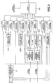
- Fig.5 is a view exemplarily showing an imaging scene for describing the iris control at the spot mode executed in the color image pickup device.
- Fig.6 is a view exemplarily showing an imaging scene for describing the iris control at the spot mode executed in the color image pickup device.
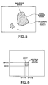
- Fig.7 is a view exemplarily showing an example of a function for defining a weight added to the skin tone mode for describing the iris control at the intelligent mode executed in the color image pickup device.
- Fig.8 is a view exemplarily showing an example of a luminance distribution of an imaging scene for describing the iris shift operation at the intelligent mode.
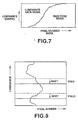
- Fig.9 is a view exemplarily showing an example of a luminance distribution of an imaging scene for describing the one-push operation at the intelligent mode.
- Fig.10 is a flowchart showing a procedure for doing the one-push operation executed in the system controller included in the color image pickup device.
- the color image pickup device as shown in Fig.1 includes an image pickup unit 10, an analog-to-digital (A/D) converting nit 30 for receiving three primary color imaging signals R, G and B obtained from the image pickup unit 10 through an analog signal processing unit 20, a digital signal processing unit 40 and an iris control unit 60 for receiving these color imaging data R, G and B digitized by the A/D converting unit 30, an ancoder 50 for receiving a digital luminance signal Y and two digital color difference signals CR and CB generated by the digital signal processing unit 40, a system controller 70 connected to the iris control unit 60, and an operation unit 80 connected to the system controller 70.
- A/D analog-to-digital
- the image pickup unit 10 is a color image pickup unit provided with means for controlling light quantity. For example, imaging light enters into the image pickup unit 10 from an imaging lens 11 through an iris diaphragm 12. In the image pickup unit 10, the imaging light is separated into three primary color light components through the effect of a color separating prism 13. Then, the three pictures of each primary color are picked up by three CCD image sensors 14R, 14G and 14B. The iris diaphragm 12 is acted as means for controlling light quantity.
- the color imaging signals R, G and B, obtained by the CCD image sensors 14R, 14G and 14G that operate to pick up the three primary color images of an object image, are supplied to the A/D converting unit 30 through the analog signal processing unit 20.
- the analog signal processing unit 20 performs analog signal processing containing various kinds of level controls such as noise removal done by correlated double sampling (CDS), gain control, black balance, white balance and shooting correction with respect to the color imaging signals R, G and B read from the corresponding CCD image sensors contained in the imaging unit 10
- level controls such as noise removal done by correlated double sampling (CDS), gain control, black balance, white balance and shooting correction with respect to the color imaging signals R, G and B read from the corresponding CCD image sensors contained in the imaging unit 10
- the A/D converting unit 30 includes A/D converters 30R, 30G and 30B, which perform the corresponding A/D converting processes at a clock rate equal to the sampling rate of each analog color imaging signal R, G or B and in synchronous to a driving clock. As a result, the color imaging signals R, G and B are digitized. The digital color signals R, G and B converted by the A/D converting unit 3 are supplied to the digital signal processing unit 40 and the iris control unit 60.
- the digital signal processing unit 40 performs nonlinear processing such as picture emphasis, pedestal addition, gamma correction and knee characteristic correction with respect to the digital color signals R, G and B supplied from the A/D converting unit 30. Further, a matrix operation is executed to generate a digital luminance signal Y and two digital color difference signals CR and CB on these digital color signals R, G and B. The digital luminance signal Y and the two digital color difference signals CR and CB generated by the digital signal processing unit 40 are supplied to the encoder 50.
- the encoder 50 operates to generats a luminance signal Y and a chromatic signal C according to the NTSC or PAL from the digital luminance signal Y and the two digital color difference signals CR and CB generated by the digital signal processing unit 40.
- the iris control unit 60 is served as level sensing means for sensing an output level of an image picked up by the imaging unit 10 and control means for controlling means for controlling light quantity of the color image pickup unit.
- This iris control unit 6 is arranged as shown in Fig.2.
- this iris control unit 60 is arranged to have a luminance converting circuit 61, first to fourth area generators 62A to 62D, first to fourth integrators 63A to 63D, first to fourth counters 64A to 64D and an iris controller 65.
- the digital color signals R, G and B digitized by the A/D converting unit 3 are supplied to the luminance converting circuit 61 and the fourth area generator 62D.
- the luminance converting circuit 61 is served as luminance converting means for converting the color imaging signal obtained by the color imaging unit into a luminance signal.
- the digital color signal R, G and B digitized by the A/D converting unit 3 are converted into a digital luminance signal Y.
- the digital luminance signal Y obtained by the luminance converting circuit 61 is supplied to the third area generator 62C as well as the first to the fourth integrators 63A to 63D.
- the first to the fourth area generators 62A to 62D operate to generate the corresponding gate pulses in the corresponding specific areas contained in the imaged screen. These gate pulses are supplied to the corresponding first to fourth integrators 63A to 63D and first to fourth counters 64A to 64D.
- the first area generator 62A is arranged to supply the gate pulse for the overall imaged screen as its specific area to the first integrator 63A and the first counter 64A.
- the second area generator 62B is arranged to supply the gate pulse for a rectangle area SPOT located on the center of the imaged screen as its specific area to the second integrator 63B and the second counter 64B.
- the third area generator 62C is arranged to supply the first and the second gate pulses for a specific luminance level area of the imaged screen as its specific area to the third integrator 63C and the third counter 64C.
- the third area generator 62C is composed of first and second reference level generators 66 and 67 and first and second level comparators 68 and 69.
- the first level comparator 68 operates to compare a reference upper limit level IRSHI generated by the first reference level generator 66 with a digital luminance signal Y obtained by the luminance converting circuit 61 in magnitude. If the digital luminance signal Y is equal to or lower than the reference upper limit level IRSHI, the comparator 66 operates to output the first luminance gate pulse.
- the second level comparator 69 operates to compare a reference lower limit lev IRSLO generated by the second reference level comparator 67 with the digital luminance signal Y obtained by the luminance converting circuit 61 in magnitude. If the digital luminance signal Y is greater than or equal to the reference lower limit level IRSLO, the comparator 69 operates to output the second luminance gate pulse. Further, the first and the second reference level generators 66 and 67 may have the reference upper limit level IRSHI and the reference lower limit level IRSLO varied under the control of the system controller 70.
- the fourth area generator 62D is arranged to supply the gate pulse for a skin tone area of the imaged screen as its specific area to the fourth integrator 63D and the fourth counter 64D.
- the fourth area generator 62D operates to decode the digital color signals R, G and B supplied from the A/D converting unit 3 for sensing the skin tone area and thereby generating the gate pulse.
- the first to the fourth integrators 63A to 63D are arranged to integrate the digital luminance signal Y obtained by the luminance converting circuit 61 within each specific area, based on the gate pulses for the specific areas inside of the imaged screen generated by the first to the fourth area generators 62A to 62D and then to supply each integral value to the iris controller 65.
- the first counter 64A operates to integrate the digital luminance signal Y with the overall imaged screen as its specific area and supply the integral value to the iris controller 65.
- the second integrator 63B operates to integrate the digital luminance signal Y with the rectangle area SPOT located on the center of the imaged acreen as its specific area and to supply the integral value to the iris controller 65
- the third integrator 63C operates to integrate the digital luminance signal Y with a specific luminance level area inside of the imaged screen as its specific area and then to supply the integral value to the iris controller 65.
- the fourth integrator 63D operates to integrate the digital luminance signal Y with the skin tone area inside of the imaged screen as its specific area and then supply the integral value to the iris controller 65.
- the first to the fourth counters 64A to 64D are arranged to count the number of pixels contained in each specific area based on the gate pulse for each specific area inside of the imaged screen generated by the first to the fourth area generators 62A to 62D and then to supply each count value to the iris controller 65.
- the first integrator 63A operates to count the number of pixels with the overall imaged screen as its specific area and supply the count value to the iris controller 65.
- the second integrator 64B operates to count the number of pixels with the rectangle area SPOT located on the center of the imaged screen as its specific area and to supply the count value to the iris controller 65.
- the third integrator 64C operates to count the number of pixels with a specific luminance level area inside of the imaged screen as its specific area and then to supply the count value to the iris controller 65.
- the fourth counter 64D operates to count the number of pixels contained in the skin tone area inside of the imaged screen as its specific area and then to supply the count value to the iris controller 65.
- the operation mode of the iris controller 65 is switched by the system controller 70 in response to the operating input of the operation unit 80.
- the iris controller 65 is operated to perform the following iris controls at various modes, based on the integral value of the digital luminance signal Y of each specific area obtained by the first to the fourth integrators 63A to 63D and the count value indicating the number of the pixels inside of each specific area obtained by the first to the fourth counters 64A to 64D.
- the iris diaphragm 12 of the image pickup unit 10 is controlled to derive an average picture level (APL) of the overall imaged screen from the integral value of the digital luminance signal Y that specifies the overall imaged screen as its specific area, which value is produced by the first integrator 63A, and the number of pixels that specifies the overall imaged screen as its specific area, which number is obtained as a count value of the first counter 64A, and adjust the average picture level to a predetermined level.
- APL average picture level
- the iris diaphragm 12 of the image pickup unit 10 is controlled to derive an average picture level PSPT of the rectangle area SPOT from an integral value SSACM of the digital luminance signal Y that specifies the rectangle area APOT located on the center of the imaged screen as its specific area, which value is produced by the second integrator 63B, and the number of pixels of the rectangle area SPOT that is obtained as a count value of the second counter 64B and adjust the average picture level to a predetermined level.
- the gate signal of the rectangle area SPOT is multiplied by the input signal and then is output as a sensing signal.
- the iris diaphragm 12 of the image pickup unit 10 is controlled to derive an average picture level PMID of the area of the specific luminance level from an integral value MIDACM of the digital luminance signal Y that specifies the specific luminance level area inside of the imaged screen as its specific area, which value is produced by the third integrator 63C, and the number of pixels MIDPIX of the specific luminance level area that is obtained as a count value of the third counter 64c and adjust the average picture level to a predetermined level.
- the luminance gate signal is multiplied by the input signal and then is output as a sending signal.
- the iris value is not influenced by a too much brighter portion or a too much gloomier portion than the specified bright range (that is close to the brightness of the object). Hence, even the backlight, the excessive light, or the invasion of illumination or the sun into the screen does not bring about the shadow or the halation on the target object.
- the change of the lighting condition may be determined. For example, if the value HIPIX is far much larger than the value of MIDPIX or LOPIX, the iris diaphragm is opened too much.
- the color gate signal is multiplied by the input signal and then is output as a sensing signal.
- the iris diaphragm 12 of the image pickup unit 10 is controlled to derive a middle value between the average picture level PMID of the specific level area at the luminance gate mode and the average picture level PSKN at the skin tone mode as the average picture level PINT and adjust the middle picture level PINT into a predetermined level.
- the operation is executed to change a mixing ratio of the luminance gate mode to the skin tone mode according to the pixel number SKPIX of the skin tone area, as shown in Fig.7, gradually shift the mode from the luminance gate mode to the skin tone mode as increasing the area of the skin tone area.
- the system controller 70 is operated to control the first and the second reference level generators 66 and 67 in a manner to shift both or one of the upper limit IRSHI and the lower limit IRSLO of the luminance at the luminance gate mode in response to the operating input of an up-down switch located on the operation panel 80.
- this control makes it possible to fine tune the characteristic of the automatic iris-control. That is, for example, as shown in Fig. 8, if the range of the luminance to be detected is shifted downward, it is determined that the screen is made gloomier, so that the automatic iris-control is executed to open the iris 12. The characteristic of the automatic iris-control is shifted to a bit brighter.
- the system controller 70 in response to an operating input of the one-push button located on the operation panel 80, the system controller 70 is operated to reset the upper limit IRSHIT and the lower limit IRSLO of the luminance at the luminance gate mode according to the procedure shown in Fig. 10.
- the system controller 70 in response to an operating input of the one-push button located on the operation panel 80, the system controller 70 is operated to set the spot mode to one field period immediately after the receipt of the input and derive the average picture level PSPT of the rectangle area SPOT located on the center of the imaged screen (step S1) and to control the iris diaphragm 12 of the image pickup unit 10 to adjust the average picture level PSPT into a predetermined level (step S2).
- the target object when operating the one-push button, the target object is positioned on the rectangle area SPOT located on the center of the imaged screen. This positioning makes it possible to properly do the automatic iris-down for the target object.
- the system controller 70 iteratively determines if the operating input of the one-push button is received again (step S4).
- the receipt of the second operating input results in returning the upper limit IRSHI and the lower limit IRSLO of the luminance at the luminance gate mode to a default value and returning the mode to he normal intelligent mode.
- An illustrative color image pickup device as described hereinbefore includes first level sensing means for sensing an imaging output level inside of the specific luminance level area on the imaged screen, second level sensing means for sensing an imaging output level of a skin tone area on the imaged screen, and control means for controlling means for controlling light quantity of the color image pickup unit based on each of the detected outputs.
- the color image pickup device enables to produce an imaging output having excellent image quality secured therein by switching the control mode of the exposure according to the imaging condition.
- the level sensing means includes luminance converting means for converting the color imaging output signal produced by the color image pickup unit, for example, into a luminance signal and the first level sensing means for sensing a luminance signal level of a specific luminance level area specified by the first area generating means based on the luminance signal and thus enables to detect the imaging output level of the specific luminance level area on the imaged screen.
- the level sensing means includes the second level sensing means for sensing the signal level of the skin tone area specified by the second area generating means based on the color imaging output signal from the luminance signal supplied from the luminance converting means and thus enables to detect the imaging output level inside of the skin tone area on the imaged screen.
- control means is operated to control the light quantity control means to adjust the first average signal level produced as the sensing output by the first level sensing means, the second average signal level produced as the sensing output by the second level sensing means or the middle signal level between the first average signal level and the second average signal level to a predetermined level.
- This control makes it possible to switch the control mode of the exposure according to the imaging condition, for producing the imaging output having excellent image quality secured therein.
- control means is operated to adjust the interior divisional point between the first average signal level and the second average signal level into the middle signal level and an area ratio of the specific luminance level area to the skin tone area into the interior divisional ratio. This adjustment makes it possible to automatically switch the control mode of the exposure according to the condition of the target object, for producing the imaging output having excellent image quality secured therein.
Landscapes
- Engineering & Computer Science (AREA)
- Multimedia (AREA)
- Signal Processing (AREA)
- Physics & Mathematics (AREA)
- Power Engineering (AREA)
- Electromagnetism (AREA)
- Condensed Matter Physics & Semiconductors (AREA)
- General Physics & Mathematics (AREA)
- Computer Hardware Design (AREA)
- Microelectronics & Electronic Packaging (AREA)
- Color Television Image Signal Generators (AREA)
- Studio Devices (AREA)
Abstract
Description
- The present invention relates to a color image pickup device.
- In general, for obtaining a pick-up output having excellent quality secured therein, an image pickup device is required to pick up an image in proper exposure to light. The image pickup device is arranged to detect a signal level of an image picked by an image pickup unit and automatically control an iris diaphragm of the image pickup unit according to the detected signal level. The conventional image pickup device operates to detect the signal of the overall pick-up image covering the background and automatically control an iris diaphragm based on the detected result. In order to correct the exposure, the conventional image pickup device performs the automatic iris control that operates to change an interior divisional ratio of a peak value to an average luminance level of an overall screen for shifting a target value to a bright or a dark side.
- In general, for obtaining a pick-up output having excellent quality secured therein, an image pickup device is required to pick up an image in proper exposure to light. The image pickup device is arranged to detect a signal level of an image picked by an image pickup unit and automatically control an iris diaphragm of the image pickup unit according to the detected signal level. The conventional image pickup device operates to detect the signal of the overall pick-up image covering the background and automatically control an iris diaphragm based on the detected result. In order to correct the exposure, the conventional image pickup device performs the automatic iris control that operates to change an interior divisional ratio of a peak value to an average luminance level of an overall screen for shifting a target value to a bright or a dark side.
- A conventional color image pickup device has been arranged to detect the signal level of the pick-up image for the overall screen covering the background and automatically control an iris diaphragm based on the detected signal level. Hence, the aperture value is influenced by the signal level of the picked image of the overall screen except a target object, such as its background. It means that the signal level of the pick-up background image may obstruct the proper aperture value to the target object.
- For example, the target object may be made shadowed in a backlighted condition, while it may be subject to halation in an excessively lighted condition. The brightness of the background may be an obstacle to proper brightness of the target object. Further, for correcting the exposure, the automatic iris control executed in the conventional image pickup device is arranged to change an interior divisional ratio of a peak value to an average luminance level of the overall screen for shifting the target value to a bright or a dark side. This control results in giving an adverse effect on the aperture value of a highly luminous portion however long the area may be. Moreover, the small difference between the peak value and the average luminance level may result in disadvantageously restricting the shifting amount. Further, the conventional image pickup device performs the iris control for the overall screen. Hence, disadvantageously, it cannot provide a proper aperture value for a specific area of the screen.
- In consideration of the foregoing conventional disadvantages an embodiment of the invention seeks to provide an image pickup device that enables to control the exposure so that the brightness of the target object is made proper independently of the brightness of the background, for the purpose of producing an image of excellent quality. Another embodiment seeks to provide an image pickup device that enables to produce an image of excellent quality of by switching a control mode of exposure according to the imaging condition.
- An embodiment of an image pickup device according to the present invention includes first level sensing means for sensing an imaging output level inside of the specific luminance level area on the imaged screen, second level sensing means for sensing an imaging output level of a skin tone area on the imaged screen, and control means for controlling means for controlling light quantity of the color image pickup unit based on each of the sensing output signals obtained by the image pickup unit having means for controlling quantity of light. Hence, the color image pickup device enables to produce an imaging output having excellent image quality secured therein by switching the control mode of the exposure according to the imaging condition.
- In an image pickup device according to the embodiment, the control means operates to control the means for controlling quantity of light provided in the image pickup unit so that the imaging output level inside of the specific area of the imaged screen detected by the second level sensing means is adjusted to a predetermined level and includes means for changing a setting of the specific luminance area detected by the first level sensing means so that the specific luminance level area may contain the imaging output level. Hence, the image pickup device enables to perform a proper automatic iris control for a target object.
- Another embodiment of a color image pickup device according to the present invention includes a color image pickup unit having means for controlling quantity of light, level sensing means having first level sensing means for sensing a signal output level of a pick-up image of a specific luminance level on the image screen based on a color imaging signal obtained by the color image pickup unit and second level sensing means for sensing a signal output level of a pick-up image of a skin tone area an the image screen, and control means for controlling means for controlling light quality of the color image pickup unit based on each detected output of the level sensing means.
- In a color image pickup device according to the other embodiment, the first level sensing means operates to detect a signal level of an area of a specific luminance level specified by first area generating means and contained in a luminance signal fed form luminance converting means for converting the color imaging signal obtained by the color image pickup unit. The second level sensing means operates to detect a signal level of a skin tone area specified by second area generating means and contained in a luminance fed from the luminance converting means. The control means operates to control the means for controlling light quality of the color image pickup unit so that a first average signal level obtained as the detected output by the first level sensing means, a second average signal level obtained as the output by the second level sensing means or a middle signal level between the first average signal level and the second average signal level is made to be a predetermined level. Further, the control means operates to adjust the interior divisional point between the first average signal level and the second average signal level into the middle signal level and an area ratio of the area of the specific luminance level to the skin tone area into an interior divisional ratio.
- For a better understanding of the present invention, reference will now be made, by way of example, to the accompanying drawings, in which:
- Fig.1 is a block diagram showing a schematic arrangement of a color image pickup device according to the present invention.
- Fig.2 is a block diagram showing an arrangement of an iris control unit included in the color image pickup device.
- Fig.3 is a view exemplarily showing an example of a luminance distribution of an imaging scene for describing the iris control at the luminance gate mode in the color image pickup device.
- Fig.4 is a view exemplarily showing an example of a luminance distribution of an imaging scene for describing the iris control at the luminance gate mode in the backlighted condition or excessive lighted condition.
- Fig.5 is a view exemplarily showing an imaging scene for describing the iris control at the spot mode executed in the color image pickup device.
- Fig.6 is a view exemplarily showing an imaging scene for describing the iris control at the spot mode executed in the color image pickup device.
- Fig.7 is a view exemplarily showing an example of a function for defining a weight added to the skin tone mode for describing the iris control at the intelligent mode executed in the color image pickup device.
- Fig.8 is a view exemplarily showing an example of a luminance distribution of an imaging scene for describing the iris shift operation at the intelligent mode.
- Fig.9 is a view exemplarily showing an example of a luminance distribution of an imaging scene for describing the one-push operation at the intelligent mode.
- Fig.10 is a flowchart showing a procedure for doing the one-push operation executed in the system controller included in the color image pickup device.
- An illustrative color image pickup device according to the present invention is arranged as shown in Fig.1. The color image pickup device as shown in Fig.1 includes an
image pickup unit 10, an analog-to-digital (A/D) convertingnit 30 for receiving three primary color imaging signals R, G and B obtained from theimage pickup unit 10 through an analogsignal processing unit 20, a digitalsignal processing unit 40 and aniris control unit 60 for receiving these color imaging data R, G and B digitized by the A/D converting unit 30, anancoder 50 for receiving a digital luminance signal Y and two digital color difference signals CR and CB generated by the digitalsignal processing unit 40, asystem controller 70 connected to theiris control unit 60, and an operation unit 80 connected to thesystem controller 70. - The
image pickup unit 10 is a color image pickup unit provided with means for controlling light quantity. For example, imaging light enters into theimage pickup unit 10 from animaging lens 11 through aniris diaphragm 12. In theimage pickup unit 10, the imaging light is separated into three primary color light components through the effect of a color separating prism 13. Then, the three pictures of each primary color are picked up by threeCCD image sensors iris diaphragm 12 is acted as means for controlling light quantity. - The color imaging signals R, G and B, obtained by the
CCD image sensors D converting unit 30 through the analogsignal processing unit 20. - The analog
signal processing unit 20 performs analog signal processing containing various kinds of level controls such as noise removal done by correlated double sampling (CDS), gain control, black balance, white balance and shooting correction with respect to the color imaging signals R, G and B read from the corresponding CCD image sensors contained in theimaging unit 10 - Further, the A/
D converting unit 30 includes A/D converters signal processing unit 40 and theiris control unit 60. - The digital
signal processing unit 40 performs nonlinear processing such as picture emphasis, pedestal addition, gamma correction and knee characteristic correction with respect to the digital color signals R, G and B supplied from the A/D converting unit 30. Further, a matrix operation is executed to generate a digital luminance signal Y and two digital color difference signals CR and CB on these digital color signals R, G and B. The digital luminance signal Y and the two digital color difference signals CR and CB generated by the digitalsignal processing unit 40 are supplied to theencoder 50. - The
encoder 50 operates to generats a luminance signal Y and a chromatic signal C according to the NTSC or PAL from the digital luminance signal Y and the two digital color difference signals CR and CB generated by the digitalsignal processing unit 40. - Further, the
iris control unit 60 is served as level sensing means for sensing an output level of an image picked up by theimaging unit 10 and control means for controlling means for controlling light quantity of the color image pickup unit. This iris control unit 6 is arranged as shown in Fig.2. - That is, this
iris control unit 60 is arranged to have aluminance converting circuit 61, first tofourth area generators 62A to 62D, first to fourth integrators 63A to 63D, first to fourth counters 64A to 64D and aniris controller 65. The digital color signals R, G and B digitized by the A/D converting unit 3 are supplied to theluminance converting circuit 61 and thefourth area generator 62D. - The
luminance converting circuit 61 is served as luminance converting means for converting the color imaging signal obtained by the color imaging unit into a luminance signal. The digital color signal R, G and B digitized by the A/D converting unit 3 are converted into a digital luminance signal Y. The digital luminance signal Y obtained by theluminance converting circuit 61 is supplied to thethird area generator 62C as well as the first to the fourth integrators 63A to 63D. - The first to the
fourth area generators 62A to 62D operate to generate the corresponding gate pulses in the corresponding specific areas contained in the imaged screen. These gate pulses are supplied to the corresponding first to fourth integrators 63A to 63D and first to fourth counters 64A to 64D. - Herein, the
first area generator 62A is arranged to supply the gate pulse for the overall imaged screen as its specific area to the first integrator 63A and the first counter 64A. - The
second area generator 62B is arranged to supply the gate pulse for a rectangle area SPOT located on the center of the imaged screen as its specific area to thesecond integrator 63B and thesecond counter 64B. - Further, the
third area generator 62C is arranged to supply the first and the second gate pulses for a specific luminance level area of the imaged screen as its specific area to thethird integrator 63C and thethird counter 64C. Thethird area generator 62C is composed of first and secondreference level generators second level comparators first level comparator 68 operates to compare a reference upper limit level IRSHI generated by the firstreference level generator 66 with a digital luminance signal Y obtained by theluminance converting circuit 61 in magnitude. If the digital luminance signal Y is equal to or lower than the reference upper limit level IRSHI, thecomparator 66 operates to output the first luminance gate pulse. Thesecond level comparator 69 operates to compare a reference lower limit lev IRSLO generated by the secondreference level comparator 67 with the digital luminance signal Y obtained by theluminance converting circuit 61 in magnitude. If the digital luminance signal Y is greater than or equal to the reference lower limit level IRSLO, thecomparator 69 operates to output the second luminance gate pulse. Further, the first and the secondreference level generators system controller 70. - Further, the
fourth area generator 62D is arranged to supply the gate pulse for a skin tone area of the imaged screen as its specific area to thefourth integrator 63D and thefourth counter 64D. Thefourth area generator 62D operates to decode the digital color signals R, G and B supplied from the A/D converting unit 3 for sensing the skin tone area and thereby generating the gate pulse. - The first to the fourth integrators 63A to 63D are arranged to integrate the digital luminance signal Y obtained by the
luminance converting circuit 61 within each specific area, based on the gate pulses for the specific areas inside of the imaged screen generated by the first to thefourth area generators 62A to 62D and then to supply each integral value to theiris controller 65. The first counter 64A operates to integrate the digital luminance signal Y with the overall imaged screen as its specific area and supply the integral value to theiris controller 65. Thesecond integrator 63B operates to integrate the digital luminance signal Y with the rectangle area SPOT located on the center of the imaged acreen as its specific area and to supply the integral value to theiris controller 65, Thethird integrator 63C operates to integrate the digital luminance signal Y with a specific luminance level area inside of the imaged screen as its specific area and then to supply the integral value to theiris controller 65. Further, thefourth integrator 63D operates to integrate the digital luminance signal Y with the skin tone area inside of the imaged screen as its specific area and then supply the integral value to theiris controller 65. - The first to the fourth counters 64A to 64D are arranged to count the number of pixels contained in each specific area based on the gate pulse for each specific area inside of the imaged screen generated by the first to the
fourth area generators 62A to 62D and then to supply each count value to theiris controller 65. The first integrator 63A operates to count the number of pixels with the overall imaged screen as its specific area and supply the count value to theiris controller 65. Thesecond integrator 64B operates to count the number of pixels with the rectangle area SPOT located on the center of the imaged screen as its specific area and to supply the count value to theiris controller 65. Thethird integrator 64C operates to count the number of pixels with a specific luminance level area inside of the imaged screen as its specific area and then to supply the count value to theiris controller 65. And, thefourth counter 64D operates to count the number of pixels contained in the skin tone area inside of the imaged screen as its specific area and then to supply the count value to theiris controller 65. - Moreover, the operation mode of the
iris controller 65 is switched by thesystem controller 70 in response to the operating input of the operation unit 80. Theiris controller 65 is operated to perform the following iris controls at various modes, based on the integral value of the digital luminance signal Y of each specific area obtained by the first to the fourth integrators 63A to 63D and the count value indicating the number of the pixels inside of each specific area obtained by the first to the fourth counters 64A to 64D. - At the full-screen mode, the
iris diaphragm 12 of theimage pickup unit 10 is controlled to derive an average picture level (APL) of the overall imaged screen from the integral value of the digital luminance signal Y that specifies the overall imaged screen as its specific area, which value is produced by the first integrator 63A, and the number of pixels that specifies the overall imaged screen as its specific area, which number is obtained as a count value of the first counter 64A, and adjust the average picture level to a predetermined level. - At the spot mode, the
iris diaphragm 12 of theimage pickup unit 10 is controlled to derive an average picture level PSPT of the rectangle area SPOT from an integral value SSACM of the digital luminance signal Y that specifies the rectangle area APOT located on the center of the imaged screen as its specific area, which value is produced by thesecond integrator 63B, and the number of pixels of the rectangle area SPOT that is obtained as a count value of thesecond counter 64B and adjust the average picture level to a predetermined level. At this spot mode, as shown in Fig.6, the gate signal of the rectangle area SPOT is multiplied by the input signal and then is output as a sensing signal. At this spot mode, the average picture level PSPT may be derived from a horizontal start position SPTHS and a horizontal end position SPTHE and a vertical start position SPTVS and a vertical end position SPHTVE by the expression of:
- At a luminance gate mode, the
iris diaphragm 12 of theimage pickup unit 10 is controlled to derive an average picture level PMID of the area of the specific luminance level from an integral value MIDACM of the digital luminance signal Y that specifies the specific luminance level area inside of the imaged screen as its specific area, which value is produced by thethird integrator 63C, and the number of pixels MIDPIX of the specific luminance level area that is obtained as a count value of the third counter 64c and adjust the average picture level to a predetermined level. At the luminance gate mode, as shown in Fig.3, the luminance gate signal is multiplied by the input signal and then is output as a sending signal. At this luminance gate mode, thesystem controller 70 is operated to specify the upper limit IRSHI and the lower limit IRSLO of the luminance and derive the average picture level PMID about a specific area where only the pixels having the luminance level kept within that specific luminance level are detectd by the expression of:
- At a skin tone mode, the
iris diaphragm 12 of theimage pickup unit 10 is controlled to derive an average picture level PSKN of the skin tone area from an integral value SSACM of the digital luminance signal Y that specifies the skin tone area inside of the imaged screen, which value is produced by thefourth integrator 63D, and the number of pixels SKPIX that specifies the skin tone area as its specific area, which number is obtained as a count value of thefourth counter 64D, by the following expression of:
- At an intelligent mode, which is a combination of the luminance gate mode and the skin tone mode, the
iris diaphragm 12 of theimage pickup unit 10 is controlled to derive a middle value between the average picture level PMID of the specific level area at the luminance gate mode and the average picture level PSKN at the skin tone mode as the average picture level PINT and adjust the middle picture level PINT into a predetermined level. At this intelligent mode, the operation is executed to change a mixing ratio of the luminance gate mode to the skin tone mode according to the pixel number SKPIX of the skin tone area, as shown in Fig.7, gradually shift the mode from the luminance gate mode to the skin tone mode as increasing the area of the skin tone area. That is, the average picture level PINT at this intelligent mode is derived by the expression of:


- At this intelligent mode, the
system controller 70 is operated to control the first and the secondreference level generators iris 12. The characteristic of the automatic iris-control is shifted to a bit brighter. - Further, at this intelligent mode, in response to an operating input of the one-push button located on the operation panel 80, the
system controller 70 is operated to reset the upper limit IRSHIT and the lower limit IRSLO of the luminance at the luminance gate mode according to the procedure shown in Fig. 10. - That is, in response to an operating input of the one-push button located on the operation panel 80, the
system controller 70 is operated to set the spot mode to one field period immediately after the receipt of the input and derive the average picture level PSPT of the rectangle area SPOT located on the center of the imaged screen (step S1) and to control theiris diaphragm 12 of theimage pickup unit 10 to adjust the average picture level PSPT into a predetermined level (step S2). For example, one example of the state of the luminance distribution of the imaged screen before and after the operation of the one-push button, as shown in Figs.9A and 9B, is rearranged to reset the upper limit IRSHI and the lower limit IRSLO of the luminance at the luminance gate mode as follows so that the average picture level PSPT of the rectangle area SPOT is located on the center of the imaged screen (step S3):

- Hence, when operating the one-push button, the target object is positioned on the rectangle area SPOT located on the center of the imaged screen. This positioning makes it possible to properly do the automatic iris-down for the target object.
- The
system controller 70 iteratively determines if the operating input of the one-push button is received again (step S4). The receipt of the second operating input results in returning the upper limit IRSHI and the lower limit IRSLO of the luminance at the luminance gate mode to a default value and returning the mode to he normal intelligent mode. - An illustrative color image pickup device as described hereinbefore includes first level sensing means for sensing an imaging output level inside of the specific luminance level area on the imaged screen, second level sensing means for sensing an imaging output level of a skin tone area on the imaged screen, and control means for controlling means for controlling light quantity of the color image pickup unit based on each of the detected outputs. Hence, the color image pickup device enables to produce an imaging output having excellent image quality secured therein by switching the control mode of the exposure according to the imaging condition.
- In the illustrative color image pickup device the level sensing means includes luminance converting means for converting the color imaging output signal produced by the color image pickup unit, for example, into a luminance signal and the first level sensing means for sensing a luminance signal level of a specific luminance level area specified by the first area generating means based on the luminance signal and thus enables to detect the imaging output level of the specific luminance level area on the imaged screen.
- In the illustrative color image pickup device the level sensing means includes the second level sensing means for sensing the signal level of the skin tone area specified by the second area generating means based on the color imaging output signal from the luminance signal supplied from the luminance converting means and thus enables to detect the imaging output level inside of the skin tone area on the imaged screen.
- Further, in the illustrative color image pickup device for example, the control means is operated to control the light quantity control means to adjust the first average signal level produced as the sensing output by the first level sensing means, the second average signal level produced as the sensing output by the second level sensing means or the middle signal level between the first average signal level and the second average signal level to a predetermined level. This control makes it possible to switch the control mode of the exposure according to the imaging condition, for producing the imaging output having excellent image quality secured therein.
- Moreover, in the illustrative color image pickup device the control means is operated to adjust the interior divisional point between the first average signal level and the second average signal level into the middle signal level and an area ratio of the specific luminance level area to the skin tone area into the interior divisional ratio. This adjustment makes it possible to automatically switch the control mode of the exposure according to the condition of the target object, for producing the imaging output having excellent image quality secured therein.
Claims (5)
- A color image pickup apparatus comprising:a color image pickup means for generating a color image signal based upon incident light thereon;iris control means for controlling iris of said image pickup means;level detecting means having first level detecting means for detecting an output level of said color image signal within first areas having a predetermined luminance level, and second level detecting means for detecting an output level of said color image signal within second areas having a predetermined tone, andcontrol means for controlling said iris control means, based on output signals of said level detecting means.
- A color image pickup apparatus as claim in claim 1, wherein said control means controls said iris control means based upon an area ratio of said first areas and said second areas.
- A color image pickup apparatus as claimed in claim 1, wherein said second level detecting means detects the output level of said color signal of skin tone areas.
- An image pickup apparatus comprising:image pickup means for generating an image signal;automatic iris means for controlling iris of said image pickup means;first average picture level detection means for detecting first average picture level of the image signal within a first area defined by a position in a frame;second averaging picture level detection means for detecting second average picture level of the image signal within a second area of which a picture level is between first threshold level and second threshold level;iris control means for controlling said automatic iris means on the basis of said first or second average picture level; andmeans for adjusting the first and second threshold level so that the first average picture level obtained when the iris controls said automatic iris means on the basis of only said first average picture level becomes center level of adjusted first and second threshold level.
- An apparatus as claim in claim 4, wherein the said first area is positioned in the center of the frame.
Applications Claiming Priority (3)
| Application Number | Priority Date | Filing Date | Title |
|---|---|---|---|
| JP9159696 | 1996-04-12 | ||
| JP91596/96 | 1996-04-12 | ||
| JP8091596A JPH09284784A (en) | 1996-04-12 | 1996-04-12 | Color image pickup device |
Publications (3)
| Publication Number | Publication Date |
|---|---|
| EP0801496A2 true EP0801496A2 (en) | 1997-10-15 |
| EP0801496A3 EP0801496A3 (en) | 1999-03-24 |
| EP0801496B1 EP0801496B1 (en) | 2001-08-16 |
Family
ID=14030946
Family Applications (1)
| Application Number | Title | Priority Date | Filing Date |
|---|---|---|---|
| EP97302473A Expired - Lifetime EP0801496B1 (en) | 1996-04-12 | 1997-04-10 | Color image pickup apparatus |
Country Status (6)
| Country | Link |
|---|---|
| US (1) | US6188434B1 (en) |
| EP (1) | EP0801496B1 (en) |
| JP (1) | JPH09284784A (en) |
| KR (1) | KR970072987A (en) |
| CN (1) | CN1168048A (en) |
| DE (1) | DE69706093T2 (en) |
Cited By (3)
| Publication number | Priority date | Publication date | Assignee | Title |
|---|---|---|---|---|
| WO2003077536A1 (en) * | 2002-03-12 | 2003-09-18 | Casio Computer Co., Ltd. | Imaging apparatus including automatic brightness adjustment function and imaging method |
| CN100437478C (en) * | 2004-02-27 | 2008-11-26 | 捷讯研究有限公司 | System and method for interactive wireless applications |
| CN106331513A (en) * | 2016-09-06 | 2017-01-11 | 深圳美立知科技有限公司 | Method and system for acquiring high-quality skin image |
Families Citing this family (10)
| Publication number | Priority date | Publication date | Assignee | Title |
|---|---|---|---|---|
| JP4169415B2 (en) * | 1999-02-08 | 2008-10-22 | 三洋電機株式会社 | Solid-state imaging device |
| JP4201424B2 (en) | 1999-02-26 | 2008-12-24 | 三洋電機株式会社 | Solid-state imaging device |
| AU2003220595A1 (en) * | 2002-03-27 | 2003-10-13 | The Trustees Of Columbia University In The City Of New York | Imaging method and system |
| JP2004157348A (en) * | 2002-11-07 | 2004-06-03 | Chinontec Kk | Projection lens apparatus and projector apparatus |
| US8107762B2 (en) | 2006-03-17 | 2012-01-31 | Qualcomm Incorporated | Systems, methods, and apparatus for exposure control |
| JP4181593B2 (en) * | 2006-09-20 | 2008-11-19 | シャープ株式会社 | Image display apparatus and method |
| KR100848118B1 (en) * | 2007-05-03 | 2008-07-24 | 삼성전자주식회사 | Biosignal-measuring instrument using photo sensor and method for controlling the photo sensor by the instrument |
| JP4831175B2 (en) | 2009-01-27 | 2011-12-07 | ソニー株式会社 | Imaging apparatus and imaging method |
| TWI404894B (en) * | 2009-12-22 | 2013-08-11 | Ind Tech Res Inst | Illumination system |
| JP2022018428A (en) * | 2020-07-15 | 2022-01-27 | 株式会社デンソー | Exposure control device, exposure control method, and exposure control program |
Citations (4)
| Publication number | Priority date | Publication date | Assignee | Title |
|---|---|---|---|---|
| JPH03148987A (en) * | 1989-11-02 | 1991-06-25 | Minolta Camera Co Ltd | Exposure controller for electronic image pickup equipment |
| US5049997A (en) * | 1989-04-10 | 1991-09-17 | Fuji Photo Film Co., Ltd. | Video camera exposure control method and apparatus for preventing improper exposure due to changing object size or displacement and luminance difference between the object and background |
| EP0552016A2 (en) * | 1992-01-13 | 1993-07-21 | Mitsubishi Denki Kabushiki Kaisha | Video signal processor and color video camera |
| US5353058A (en) * | 1990-10-31 | 1994-10-04 | Canon Kabushiki Kaisha | Automatic exposure control apparatus |
Family Cites Families (8)
| Publication number | Priority date | Publication date | Assignee | Title |
|---|---|---|---|---|
| US4506293A (en) | 1981-07-16 | 1985-03-19 | Rca Corporation | Independent fleshtone contours |
| US4987482A (en) * | 1987-10-27 | 1991-01-22 | Canon Kabushiki Kaisha | Image pickup apparatus having exposure control for human subjects |
| AU607033B2 (en) * | 1988-01-12 | 1991-02-21 | Sanyo Electric Co., Ltd. | Auto iris/gamma correction apparatus for making automatic exposure adjustment and/or automatic gamma correction in response to video signal and image sensing apparatus comprising such auto iris/gamma correction apparatus |
| US4969045A (en) * | 1988-05-20 | 1990-11-06 | Sanyo Electric Co., Ltd. | Image sensing apparatus having automatic iris function of automatically adjusting exposure in response to video signal |
| US5111301A (en) * | 1989-06-28 | 1992-05-05 | Sanyo Electric Co., Ltd. | Automatic exposure adjusting apparatus for automatically adjusting exposure by fuzzy inference |
| JP2822256B2 (en) * | 1990-02-15 | 1998-11-11 | ソニー株式会社 | Exposure compensation device for video camera |
| JP3048180B2 (en) * | 1991-02-27 | 2000-06-05 | キヤノン株式会社 | Imaging device and imaging signal processing device |
| JP3412174B2 (en) * | 1992-05-21 | 2003-06-03 | 松下電器産業株式会社 | Automatic exposure control device |
-
1996
- 1996-04-12 JP JP8091596A patent/JPH09284784A/en not_active Withdrawn
-
1997
- 1997-04-10 DE DE69706093T patent/DE69706093T2/en not_active Expired - Fee Related
- 1997-04-10 EP EP97302473A patent/EP0801496B1/en not_active Expired - Lifetime
- 1997-04-10 US US08/827,652 patent/US6188434B1/en not_active Expired - Fee Related
- 1997-04-12 CN CN97111225A patent/CN1168048A/en active Pending
- 1997-04-12 KR KR1019970013758A patent/KR970072987A/en not_active Application Discontinuation
Patent Citations (4)
| Publication number | Priority date | Publication date | Assignee | Title |
|---|---|---|---|---|
| US5049997A (en) * | 1989-04-10 | 1991-09-17 | Fuji Photo Film Co., Ltd. | Video camera exposure control method and apparatus for preventing improper exposure due to changing object size or displacement and luminance difference between the object and background |
| JPH03148987A (en) * | 1989-11-02 | 1991-06-25 | Minolta Camera Co Ltd | Exposure controller for electronic image pickup equipment |
| US5353058A (en) * | 1990-10-31 | 1994-10-04 | Canon Kabushiki Kaisha | Automatic exposure control apparatus |
| EP0552016A2 (en) * | 1992-01-13 | 1993-07-21 | Mitsubishi Denki Kabushiki Kaisha | Video signal processor and color video camera |
Non-Patent Citations (1)
| Title |
|---|
| PATENT ABSTRACTS OF JAPAN vol. 015, no. 375 (E-1114), 20 September 1991 & JP 03 148987 A (MINOLTA CAMERA CO LTD), 25 June 1991 * |
Cited By (3)
| Publication number | Priority date | Publication date | Assignee | Title |
|---|---|---|---|---|
| WO2003077536A1 (en) * | 2002-03-12 | 2003-09-18 | Casio Computer Co., Ltd. | Imaging apparatus including automatic brightness adjustment function and imaging method |
| CN100437478C (en) * | 2004-02-27 | 2008-11-26 | 捷讯研究有限公司 | System and method for interactive wireless applications |
| CN106331513A (en) * | 2016-09-06 | 2017-01-11 | 深圳美立知科技有限公司 | Method and system for acquiring high-quality skin image |
Also Published As
| Publication number | Publication date |
|---|---|
| KR970072987A (en) | 1997-11-07 |
| DE69706093T2 (en) | 2002-03-21 |
| EP0801496A3 (en) | 1999-03-24 |
| DE69706093D1 (en) | 2001-09-20 |
| EP0801496B1 (en) | 2001-08-16 |
| JPH09284784A (en) | 1997-10-31 |
| US6188434B1 (en) | 2001-02-13 |
| CN1168048A (en) | 1997-12-17 |
Similar Documents
| Publication | Publication Date | Title |
|---|---|---|
| US6570620B1 (en) | Exposure control device | |
| EP0356123B1 (en) | Control circuit for a video camera | |
| US5221963A (en) | Video camera having a video signal processing apparatus | |
| JP3207313B2 (en) | Imaging device and control method thereof | |
| US20020027601A1 (en) | Image pickup apparatus | |
| EP0801496B1 (en) | Color image pickup apparatus | |
| JPH03204281A (en) | Image pickup device | |
| JP4042432B2 (en) | Imaging device | |
| KR100609155B1 (en) | Image processing device and method for compensating a picture taken against the light using the same | |
| US4987482A (en) | Image pickup apparatus having exposure control for human subjects | |
| US6665007B1 (en) | Video camera system | |
| US6980251B1 (en) | Image sensing apparatus which carries out optimum exposure control of subject | |
| JPH0974516A (en) | Image input device | |
| JPH08280041A (en) | Image pickup device | |
| JP3100815B2 (en) | Camera white balance control method | |
| KR100492120B1 (en) | Photographing apparatus having function of back light compensation and control method thereof | |
| JP3701172B2 (en) | Camera exposure control method | |
| JPH0574271B2 (en) | ||
| JPS6361563A (en) | Image pickup device | |
| KR0185170B1 (en) | Control circuit for a video camera | |
| JPH09284640A (en) | Image pickup device | |
| JP2692854B2 (en) | Automatic exposure control device | |
| KR0134291B1 (en) | Reference value auto setting apparatus for iris contool | |
| JPH04109774A (en) | Exposure adjustment device for camera | |
| JPH0215793A (en) | White balance adjuster |
Legal Events
| Date | Code | Title | Description |
|---|---|---|---|
| PUAI | Public reference made under article 153(3) epc to a published international application that has entered the european phase |
Free format text: ORIGINAL CODE: 0009012 |
|
| AK | Designated contracting states |
Kind code of ref document: A2 Designated state(s): DE FR GB |
|
| RIN1 | Information on inventor provided before grant (corrected) |
Inventor name: TSUCHIYA, TAKASHI |
|
| PUAL | Search report despatched |
Free format text: ORIGINAL CODE: 0009013 |
|
| AK | Designated contracting states |
Kind code of ref document: A3 Designated state(s): DE FR GB |
|
| 17P | Request for examination filed |
Effective date: 19990823 |
|
| 17Q | First examination report despatched |
Effective date: 19990929 |
|
| GRAG | Despatch of communication of intention to grant |
Free format text: ORIGINAL CODE: EPIDOS AGRA |
|
| GRAG | Despatch of communication of intention to grant |
Free format text: ORIGINAL CODE: EPIDOS AGRA |
|
| GRAH | Despatch of communication of intention to grant a patent |
Free format text: ORIGINAL CODE: EPIDOS IGRA |
|
| GRAH | Despatch of communication of intention to grant a patent |
Free format text: ORIGINAL CODE: EPIDOS IGRA |
|
| GRAA | (expected) grant |
Free format text: ORIGINAL CODE: 0009210 |
|
| AK | Designated contracting states |
Kind code of ref document: B1 Designated state(s): DE FR GB |
|
| REF | Corresponds to: |
Ref document number: 69706093 Country of ref document: DE Date of ref document: 20010920 |
|
| REG | Reference to a national code |
Ref country code: GB Ref legal event code: IF02 |
|
| ET | Fr: translation filed | ||
| PGFP | Annual fee paid to national office [announced via postgrant information from national office to epo] |
Ref country code: GB Payment date: 20020410 Year of fee payment: 6 Ref country code: FR Payment date: 20020410 Year of fee payment: 6 |
|
| PGFP | Annual fee paid to national office [announced via postgrant information from national office to epo] |
Ref country code: DE Payment date: 20020417 Year of fee payment: 6 |
|
| PLBE | No opposition filed within time limit |
Free format text: ORIGINAL CODE: 0009261 |
|
| STAA | Information on the status of an ep patent application or granted ep patent |
Free format text: STATUS: NO OPPOSITION FILED WITHIN TIME LIMIT |
|
| 26N | No opposition filed | ||
| PG25 | Lapsed in a contracting state [announced via postgrant information from national office to epo] |
Ref country code: GB Free format text: LAPSE BECAUSE OF NON-PAYMENT OF DUE FEES Effective date: 20030410 |
|
| PG25 | Lapsed in a contracting state [announced via postgrant information from national office to epo] |
Ref country code: DE Free format text: LAPSE BECAUSE OF NON-PAYMENT OF DUE FEES Effective date: 20031101 |
|
| GBPC | Gb: european patent ceased through non-payment of renewal fee |
Effective date: 20030410 |
|
| PG25 | Lapsed in a contracting state [announced via postgrant information from national office to epo] |
Ref country code: FR Free format text: LAPSE BECAUSE OF NON-PAYMENT OF DUE FEES Effective date: 20031231 |
|
| REG | Reference to a national code |
Ref country code: FR Ref legal event code: ST |