EP0801317B1 - Management of optical fibre - Google Patents
Management of optical fibre Download PDFInfo
- Publication number
- EP0801317B1 EP0801317B1 EP97301323A EP97301323A EP0801317B1 EP 0801317 B1 EP0801317 B1 EP 0801317B1 EP 97301323 A EP97301323 A EP 97301323A EP 97301323 A EP97301323 A EP 97301323A EP 0801317 B1 EP0801317 B1 EP 0801317B1
- Authority
- EP
- European Patent Office
- Prior art keywords
- fibre
- cassette
- hinge
- cassettes
- splice
- Prior art date
- Legal status (The legal status is an assumption and is not a legal conclusion. Google has not performed a legal analysis and makes no representation as to the accuracy of the status listed.)
- Expired - Lifetime
Links
Images

Classifications
-
- G—PHYSICS
- G02—OPTICS
- G02B—OPTICAL ELEMENTS, SYSTEMS OR APPARATUS
- G02B6/00—Light guides; Structural details of arrangements comprising light guides and other optical elements, e.g. couplings
- G02B6/44—Mechanical structures for providing tensile strength and external protection for fibres, e.g. optical transmission cables
- G02B6/4439—Auxiliary devices
- G02B6/444—Systems or boxes with surplus lengths
- G02B6/4453—Cassettes
- G02B6/4454—Cassettes with splices
-
- G—PHYSICS
- G02—OPTICS
- G02B—OPTICAL ELEMENTS, SYSTEMS OR APPARATUS
- G02B6/00—Light guides; Structural details of arrangements comprising light guides and other optical elements, e.g. couplings
- G02B6/44—Mechanical structures for providing tensile strength and external protection for fibres, e.g. optical transmission cables
- G02B6/4439—Auxiliary devices
- G02B6/444—Systems or boxes with surplus lengths
- G02B6/4453—Cassettes
Definitions
- This invention relates to cable management and in particularly, but not exclusively, related to management of optical fibre splices.
- an apparatus for managing a plurality of optical components comprising a plurality of cassettes for holding at least one optical component, at least one cassette being moveable about a pivot axis of a hinge arrangement, the hinge arrangement including a hinge pin through which fibre is passed into the cassette, characterised in that the hinge pin is flexible.
- An advantage of guiding fibre substantially along the pivot axis through the hinge is that it is located on a "neutral axis" when a cassette is moved about its hinge. This minimises disturbance of the fibre and consequently the possibility of bending loss.
- Another advantage is that two fibres to be spliced are naturally introduced across a lower part of the cassette. This is very convenient for organising the fibre in the cassette.
- each pin may guide fibres into the cassette from opposite directions.
- the or each hinge pin may not necessarily be tubular but may have an open channel, or slot running along its length.
- the term cassette includes a tray which is capable of holding an optical component.
- the or each cassette is adapted to hold at least one optical component.
- the or each cassette is adapted to hold only one optical component and there may be a sole pair, or circuit, of fibres per tray.
- Such an embodiment is particularly, but not exclusively, suitable for cable television.
- the or each cassette may hold a number of optical circuits. The number of fibres entering a cassette may be different from the number of fibres leaving a cassette.
- the optical components are splices.
- they may be couplers, filters or other components or devices.
- the apparatus may manage components of different types, such as a combination of splices and couplers.
- the or each cassette may flip over.
- the or each cassette is moveable from a first position in which it may be flat or nearly so to a second position in which it may be flat or nearly so.
- the or each cassette may rotate about an axis by up to 180°.
- a particular cassette may only lie flat or nearly so if it is not restricted from doing so by the presence of another cassette.
- the or each cassette is supported on a support means.
- the support means may be a drawer.
- the support means may have a row or rows of connector adapters at an end.
- At least one cassette may house a splice between a connector pigtail and an uncabled fibre.
- the support means may support a plurality of cassettes arranged in a row. When flat a cassette may overlie, to an extent, a cassette adjacent to it. This provides a compact arrangement and, importantly, a flat arrangement. This is useful if the apparatus is in the form of a fibre management cabinet comprising a plurality of drawers, one above another.
- At least one cassette comprises a mandrel around which fibre may be arranged and stored.
- At least one cassette may comprise an envelope, which has a base, a peripheral wall and a lip or flange extending from the peripheral wall and overlying the base.
- the flange has one or more fibre retainers which rest on the mandrel.
- the or each retainer is resilient. It may be a thin flexible member. It may be planar. The or each retainer may be sufficiently flexible to enable it to be pulled from contact with the mandrel, thus allowing a fibre to be slipped between it and the mandrel. On release of the or each retainer it may spring back to rest on the mandrel.
- At least one cassette comprises a means for holding an optical component.
- Vacuum formed cassettes may have a one-piece construction comprising two halves. The two halves may be connected together by at least one fastener.
- the or each fastener may be mechanical such as a snap fit or a popper, for example a button which is an interference fit in a recess.
- the or each fastener is releasable.
- the vacuum formed cassettes may be assembled by bending one of the halves about a fold line to register with the other of the halves and then fastening the two halves together. This operation may also form one or more parts of the hinge which receive a hinge pin.
- a vacuum formed construction is cheap to manufacture and may be lightweight. Although it is made out of material which is perceived to be flimsy, the resultant cassette is rigid enough for its purpose.
- the inventors of the present invention have realised that very rigid splice trays are not essential to fibre management.
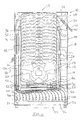
- Figure 1 shows a drawer 10 which is part of a fibre management system.
- the fibre management system is a cabinet comprising a plurality of drawers 10 which can each be slid out of the cabinet for access.
- the drawer 10 is a flat tray having a base 12 and peripheral wall 14.
- the drawer 10 has a front wall 16 and a back wall 18.
- a knob 20 is used to pull the drawer 10 out of the cabinet.
- a wall 24 of connector adaptors 26 At one side wall 22 is a wall 24 of connector adaptors 26. Although only two adaptors 26 are shown there will be an adaptor for each connector.
- splice cassettes 34 which are mounted by means of hinges 36.
- the splice trays 34 may all adopt a configuration in which they lie down all pointing towards the side wall 28 as shown in Figure 1.
- one or more of the splice trays 34 may be moved about its hinge 36 and point towards the side wall 22. That is, one or more of the splice trays may be flipped over in order to allow access to a particular splice.
- the tubular fibre guide 30 has an open end 38 from which fibre may emerge into a fibre guiding channel 42 which extends along the base 12 in a direction generally parallel to the front wall 16 of the drawer 10.
- a tubular fibre protection sleeve 32 which guides pigtails through an open end 40 into a fibre guiding channel 44.
- fibre guiding channels 42, 44 there are guide formations 46 at positions which correspond to hinges 36 of respective splice cassettes 34. These are shown in Figure 4. This also shows that the fibre guiding channel 44, guide formations 46 and hinge elements 48 are all formed on a single vacuum formed integral piece 50 which is mounted on the base 12 by means of fixings 52. A similar piece 50 forms the guide channel 42. A pair of the pieces 50 comprises a means for hingeably connecting the splice cassettes 34 to the base 12.
- FIG. 2 Another view of the drawer 10 is shown in Figure 2. This shows a cross-sectional view of the drawer 10, looking along the base 12, with one of the splice cassettes 34 upstanding.
- the splice cassette 34 has hinge formations 54 which are connected to the hinge elements 48 by means of hollow hinge pins 56.
- the function of the pins 56 is twofold, they complete the hinge 36 and also serve as fibre guides to introduce fibre from guide formations 46 into splice cassettes 34.
- the splice cassette 34 has a generally planar base 60 from which extends a mandrel 62.
- a peripheral wall 64 extends around the base 60 and is upstanding therefrom.
- An irregular lip 66 extends from the top of the peripheral wall 64 in towards the mandrel 62.
- Parts of the lip 66 which extend across the base 60 and in towards the mandrel 62 form retainers 68 for holding fibre in the splice cassette 34 in a region or envelope formed between the base 60, the peripheral wall 64 and the retainers 68.
- Some retainers 70 extend up to and partially overlap the mandrel 62 whereas others 72 do not reach the mandrel 62.
- the retainers 70 bear against an upper planar surface of the mandrel 62.
- the hinge pins 56 are anchored into the hinge elements 48 without adhesive. Rather than being drilled, holes to receive the hinge pins are pierced in a blank end of the hinge element with a spike. This creates a hole which is of a suitable size to receive a hinge pin 56. Shortly after piercing has occurred, the hinge pin 56 will fit readily into the hole in the hinge element 48. However, after piercing the pierced and deformed plastic of the hinge element 48 relaxes, contracts and pinches the hinge pin 56 to hold it in place. For manufacturing purposes it is convenient if all the hinge formations 48 in a single piece 50 can be pierced at the same time. It is not essential for hinge pins to be inserted immediately after piercing.
- a pierced piece may be stored until needed and then hinge pin receiving holes prepared with a blunt sizing tool.
- Advantages of this method are that no adhesive is required, the holes do not need to be formed by drilling or moulding (thus avoiding problems with manufacturing tolerances), and that the hole forming and hinge pin fixing procedures are relatively quick.
- the hollow hinge pins 56 are flexible enough to flex in response to bending of fibre, for example when fibre is being worked upon.
- the shape and height of the formations 46 are chosen so as to ease the entry (at 107) of the fibre ends into the hollow hinge pins 56. Grooves in the formations 46, which guide fibre to an end of a hollow hinge pin 56, guide fibre neatly into the centre of the hollow end of the hinge pin. Thus the formations accommodate a wide angle of fibre end approach.
- Each splice cassette is integrally formed as a single piece by vacuum forming.
- the single piece has a first half comprising the base 60, the mandrel 62, and the peripheral wall 64 and a second half comprising a region which also forms part of the peripheral wall 64 and the lip 66.
- the first and second halves are joined together about a fold region.
- the splice cassette is assembled by moving the second half about the fold region to register with the first half and then snapping the two halves together.
- the halves are provided with complementary snap fasteners having a button on one half which snaps into a recess on the other half where it is held by a mechanical interference fit.
- the snap fasteners are denoted by numerals 80 on Figure 2.
- first and second halves are releasable from each other. Snapping the first and second halves together may also serve as a step in the construction of the drawer. For ease of assembly, before the halves of the splice cassette 34 are snapped together they are placed between hinge elements 48 into which have been placed hollow pins 56. It may be snapping of the first and second halves together which locates the hollow pins 56 in the hinges 36. In this way the drawer forms its own jig during assembly. However, it is preferred to assemble the drawer with the splice cassettes already snapped together.
- the cassettes in a row or a stack are placed in a jig so that the hinge formations 54 are lined up and pieces 50 (already containing inserted and held hinge pins 56) are brought together on either side of the cassettes, the loose ends of the hinge pins 56 being fed into the hinge formations 54.
- the hinge pins 56 are usually cut pieces of a coil of plastic tube. As a result they will have a natural curve. It is convenient to rotate the hinge pin in the hinge elements 48 so that on sliding into hinge formations 56, the hinge pins will curve naturally towards the middle of the cassettes. When the pieces 50 and cassettes 34 are assembled, they can be lifted out of the jig together and, as a single assembly, placed on the base 12.
- the assembly is located on the base 12 so that pips which have been formed on the pieces register with holes in the base 12.
- the pips are pierced and the assembly and base 12, fixed together by fixings 52 which, conveniently, are press-studs.
- the pieces 50 are transparent so that they can be correctly positioned on the base 12 with little or no difficulty.
- the assembly is easy to handle in fixing it on to the base. Being relatively robust it may be stored for fixing to the base at a future time.
- the splice cassettes are vacuum formed they may comprise a relatively inexpensive material such as PVC. As a result the splice cassettes are more lightweight and less expensive than the relatively heavy duty injection moulded splice trays which have been available hitherto.
- a cable or a bundle of fibres is fed to an inlet end 90 of the tubular fibre guide 30. If it is a cable, the fibre or fibres it contains would be broken out at this point to be fed into the tubular fibre guide 30.
- the tubular fibre guide 30 guides the fibre around the drawer 10 such that, on emerging at the end 38, the fibres enter the channel 42 from where they can be fed into individual splice cassettes 34.
- a fibre is fed along through formations 46 and into one of the hollow pins 56. These guide the fibres away from the front and back walls 16 of the drawer and into the interior of the splice cassettes.
- Fibre is brought into the drawer 10 for the purpose of termination onto connectors for use in further interconnection.
- the row of adaptors 26 in the side wall 24 locates a number of connectors 100. In this embodiment a full complement of sixteen connectors 100 is shown although the row of side wall adaptors 26 may not be "full”.
- the connectors have fibre in the form of pigtails 102 (either fully or secondary coated) which are bundled together and fed along a channel 92 before entering the tubular fibre protection sleeve 32. This is relatively short (approximately 40mm long) and protects pigtails 102 as they pass through an anchor point 108. In Figure 1 pigtails in the channel 92 are shown schematically.
- the channel 92 guides the fibre from near the comer of the front wall 16 and side wall 22 and along the front wall 16, where the pigtails 102 arc around to the side wall 28 and into the guide channel 44.
- individual fibres are bent out of the channel 44, through guide formations 46 and into individual splice cassettes 34. Again entry into the envelope of a splice cassette 34 is via a hollow pin 56 and is made in an opposite direction to fibre entering from channel 42.
- Figure 4 shows a single fibre 104 (secondary coated) being taken from the end 40 of sleeve 32 and being fed into the end 107 of the hollow pin 56.
- the ends of the fibre from opposite ends can be prepared for splicing and then spliced.
- a resultant splice in a splice protector 130 is stored between pips 106 which extend out of the base 60 of the splice cassette 34 by pushing it underneath the retainer 72 (which is between the pips) and then over the pips such that it abuts the peripheral wall 64.
- the splice protector 130 is contained between base 60, wall 64, retainer 72 and pips 106.
- Extra fibre length is then present as loops exiting via cut-outs 131 to the left and right of the splice cassette 34.
- each loop is formed into a series of smaller loops by twisting and folding it and then is stored in the envelope. This is done by lifting retainers 70 in turn and placing part of the loops underneath until the loops are centralised around the mandrel 62.
- Each retainer 70 need be lifted only once for each extra fibre length. When released each retainer 70 springs back into contact with the mandrel 62. Once in place the retainers prevent the fibre from escaping.
- the fibres are either in a respective guide channel 42, 44, internally located in a hinge 36 or in the envelope of a splice cassette.
- Another advantage of the fibres being internally located in a hinge 36 is that any movement of the splice cassette is at a minimum about its hinge 36. By locating fibre in the hinges they suffer least disturbance and least bending. In effect the fibre is disposed along a "neutral axis" of movement of a splice cassette. Fibres may suffer a little torsion but this is within acceptable limits.
- a flexible hinge pin accommodates movement of the fibre.
- the embodiment discussed is particularly suitable for single fibre working in which optical circuits are isolated from one another, for example in cable television.
Landscapes
- Physics & Mathematics (AREA)
- General Physics & Mathematics (AREA)
- Optics & Photonics (AREA)
- Mechanical Coupling Of Light Guides (AREA)
- Light Guides In General And Applications Therefor (AREA)
Description
Claims (11)
- Apparatus (10) for managing a plurality of optical components (130), the apparatus comprising a plurality of cassettes (34) for holding at least one optical component (130), at least one cassette (34) being moveable about a pivot axis of a hinge arrangement (54, 48, 56), the hinge arrangement including a hinge pin (56) through which fibre is passed into the cassette (34), characterised in that the hinge pin is flexible.
- Apparatus according to Claim 1, characterised in that there are two hinge pins which guide respective fibres into the cassette from opposite directions.
- Apparatus according to Claim 1 or Claim 2, characterised in that the, or either or both of the hinge pins is tubular.
- Apparatus according to Claim 1 or Claim 2, characterised in that the, or either or both of the hinge pins has a longitudinal slot such that an open channel containing the fibre is formed.
- Apparatus according to any one of the preceding claims, characterised in that at least one of the cassettes (34) is vacuum-formed.
- Apparatus according to Claim 5, characterised in that the or each vacuum-formed cassette (34) comprises a one-piece construction comprising two halves (120, 122).
- Apparatus according to Claim 6, characterised in that the two halves (120, 122) are connected together by at least one mechanical fastener (80).
- Apparatus according to any one of the preceding claims, characterised in that the cassettes hold one or more optical components, at least one of which components (130) is a splice.
- Apparatus according to any one of Claims 1 to 7, characterised in that the cassettes hold one or more optical components, at least one of which components (130) is a coupler.
- Apparatus according to any one of the preceding claims, characterised in that the cassettes (34) are supported on a support means (12).
- Apparatus according to any one of the preceding claims, characterised in that it includes a fibre-management cabinet.
Applications Claiming Priority (4)
| Application Number | Priority Date | Filing Date | Title |
|---|---|---|---|
| GBGB9607609.6A GB9607609D0 (en) | 1996-04-12 | 1996-04-12 | Cable treatment |
| GB9607609 | 1996-04-12 | ||
| GB9619828 | 1996-09-23 | ||
| GB9619828A GB2312053B (en) | 1996-04-12 | 1996-09-23 | Management of optical fibres |
Publications (3)
| Publication Number | Publication Date |
|---|---|
| EP0801317A2 EP0801317A2 (en) | 1997-10-15 |
| EP0801317A3 EP0801317A3 (en) | 1997-12-17 |
| EP0801317B1 true EP0801317B1 (en) | 2002-06-26 |
Family
ID=26309114
Family Applications (1)
| Application Number | Title | Priority Date | Filing Date |
|---|---|---|---|
| EP97301323A Expired - Lifetime EP0801317B1 (en) | 1996-04-12 | 1997-02-27 | Management of optical fibre |
Country Status (3)
| Country | Link |
|---|---|
| US (1) | US5887106A (en) |
| EP (1) | EP0801317B1 (en) |
| DE (1) | DE69713544T2 (en) |
Families Citing this family (87)
| Publication number | Priority date | Publication date | Assignee | Title |
|---|---|---|---|---|
| DE29704505U1 (en) * | 1997-03-12 | 1997-04-24 | Alsthom Cge Alcatel | Device for accommodating a large number of cassettes |
| KR100261762B1 (en) * | 1997-12-02 | 2000-07-15 | 이계철 | Optical ribbon fiber splice tray |
| US6160946A (en) | 1998-07-27 | 2000-12-12 | Adc Telecommunications, Inc. | Outside plant fiber distribution apparatus and method |
| GB9909114D0 (en) * | 1999-04-21 | 1999-06-16 | Raychem Sa Nv | Optical fibre organiser |
| SE517302C2 (en) * | 1999-05-27 | 2002-05-21 | Ericsson Telefon Ab L M | Apparatus for delimiting and separating optical fibers in an isolated space |
| US6504988B1 (en) * | 2000-01-24 | 2003-01-07 | Adc Telecommunications, Inc. | Cable management panel with sliding drawer |
| US6438310B1 (en) | 2000-01-24 | 2002-08-20 | Adc Telecommunications, Inc. | Cable management panel with sliding drawer |
| US6944387B2 (en) | 2001-04-30 | 2005-09-13 | Telect, Inc. | Fiber optic connector tray system |
| US6674952B2 (en) | 2001-04-30 | 2004-01-06 | Telect, Inc. | Fiber optic cable bend radius protection system |
| US6792190B2 (en) | 2001-06-01 | 2004-09-14 | Telect, Inc. | High density fiber optic splitter/connector tray system |
| US7079744B2 (en) * | 2001-07-06 | 2006-07-18 | Adc Telecommunications, Inc. | Cable management panel with sliding drawer and methods |
| US20030063863A1 (en) * | 2001-10-02 | 2003-04-03 | Bruno Nardelli | Multi-component board assembly |
| US6829425B2 (en) | 2002-04-19 | 2004-12-07 | Plexus Corporation | Optical fiber management system and method |
| US20030219194A1 (en) * | 2002-04-19 | 2003-11-27 | Barthel William F. | Optical fiber management system and method |
| US6741785B2 (en) | 2002-04-19 | 2004-05-25 | Plexus Corporation | Optical fiber management system and method |
| US6937807B2 (en) | 2002-04-24 | 2005-08-30 | Adc Telecommunications, Inc. | Cable management panel with sliding drawer |
| KR20050047135A (en) * | 2002-10-11 | 2005-05-19 | 쓰리엠 이노베이티브 프로퍼티즈 컴파니 | Array of fiber optic splicing cassettes |
| BR0314658A (en) * | 2002-10-11 | 2005-08-02 | 3M Innovative Properties Co | Fiber Management System |
| US6804447B2 (en) * | 2002-11-05 | 2004-10-12 | Adc Telecommunications, Inc. | Fiber panel with integrated couplers |
| US6865331B2 (en) * | 2003-01-15 | 2005-03-08 | Adc Telecommunications, Inc. | Rotating radius limiter for cable management panel and methods |
| US7013074B2 (en) * | 2004-02-06 | 2006-03-14 | Corning Cable Systems Llc | Optical connection closure having at least one connector port |
| KR20080003433A (en) * | 2005-04-19 | 2008-01-07 | 에이디씨 텔레커뮤니케이션스 인코포레이티드 | Loop back plug and method |
| US20070082522A1 (en) * | 2005-10-11 | 2007-04-12 | Pierre Bonvallat | Carrier and an assembly including a carrier and a telecommunications module |
| CN101833140B (en) * | 2005-10-24 | 2012-09-05 | 3M创新有限公司 | Fiber termination platform and fiber termination method |
| US7391952B1 (en) * | 2006-08-31 | 2008-06-24 | Corning Cable Systems Llc | Pre-connectorized fiber optic cable network interconnection apparatus |
| US11294136B2 (en) | 2008-08-29 | 2022-04-05 | Corning Optical Communications LLC | High density and bandwidth fiber optic apparatuses and related equipment and methods |
| US8452148B2 (en) * | 2008-08-29 | 2013-05-28 | Corning Cable Systems Llc | Independently translatable modules and fiber optic equipment trays in fiber optic equipment |
| US8184938B2 (en) * | 2008-08-29 | 2012-05-22 | Corning Cable Systems Llc | Rear-installable fiber optic modules and equipment |
| EP2221932B1 (en) | 2009-02-24 | 2011-11-16 | CCS Technology Inc. | Holding device for a cable or an assembly for use with a cable |
| US8699838B2 (en) | 2009-05-14 | 2014-04-15 | Ccs Technology, Inc. | Fiber optic furcation module |
| US8538226B2 (en) | 2009-05-21 | 2013-09-17 | Corning Cable Systems Llc | Fiber optic equipment guides and rails configured with stopping position(s), and related equipment and methods |
| US9075216B2 (en) | 2009-05-21 | 2015-07-07 | Corning Cable Systems Llc | Fiber optic housings configured to accommodate fiber optic modules/cassettes and fiber optic panels, and related components and methods |
| ES2793952T3 (en) | 2009-06-19 | 2020-11-17 | Corning Optical Communications LLC | High Density and Bandwidth Fiber Optic Apparatus |
| CA2765830A1 (en) | 2009-06-19 | 2010-12-23 | Corning Cable Systems Llc | High fiber optic cable packing density apparatus |
| US8712206B2 (en) | 2009-06-19 | 2014-04-29 | Corning Cable Systems Llc | High-density fiber optic modules and module housings and related equipment |
| US8625950B2 (en) | 2009-12-18 | 2014-01-07 | Corning Cable Systems Llc | Rotary locking apparatus for fiber optic equipment trays and related methods |
| DE102010006611B4 (en) * | 2010-02-01 | 2012-11-08 | Adc Gmbh | Holder for at least one cassette |
| US8992099B2 (en) | 2010-02-04 | 2015-03-31 | Corning Cable Systems Llc | Optical interface cards, assemblies, and related methods, suited for installation and use in antenna system equipment |
| US8913866B2 (en) | 2010-03-26 | 2014-12-16 | Corning Cable Systems Llc | Movable adapter panel |
| CA2796221C (en) | 2010-04-16 | 2018-02-13 | Ccs Technology, Inc. | Sealing and strain relief device for data cables |
| EP2381284B1 (en) | 2010-04-23 | 2014-12-31 | CCS Technology Inc. | Under floor fiber optic distribution device |
| US8660397B2 (en) | 2010-04-30 | 2014-02-25 | Corning Cable Systems Llc | Multi-layer module |
| US9075217B2 (en) | 2010-04-30 | 2015-07-07 | Corning Cable Systems Llc | Apparatuses and related components and methods for expanding capacity of fiber optic housings |
| US8705926B2 (en) | 2010-04-30 | 2014-04-22 | Corning Optical Communications LLC | Fiber optic housings having a removable top, and related components and methods |
| US9519118B2 (en) | 2010-04-30 | 2016-12-13 | Corning Optical Communications LLC | Removable fiber management sections for fiber optic housings, and related components and methods |
| US9632270B2 (en) | 2010-04-30 | 2017-04-25 | Corning Optical Communications LLC | Fiber optic housings configured for tool-less assembly, and related components and methods |
| US8879881B2 (en) | 2010-04-30 | 2014-11-04 | Corning Cable Systems Llc | Rotatable routing guide and assembly |
| US9720195B2 (en) | 2010-04-30 | 2017-08-01 | Corning Optical Communications LLC | Apparatuses and related components and methods for attachment and release of fiber optic housings to and from an equipment rack |
| US8718436B2 (en) | 2010-08-30 | 2014-05-06 | Corning Cable Systems Llc | Methods, apparatuses for providing secure fiber optic connections |
| US9279951B2 (en) | 2010-10-27 | 2016-03-08 | Corning Cable Systems Llc | Fiber optic module for limited space applications having a partially sealed module sub-assembly |
| US8662760B2 (en) | 2010-10-29 | 2014-03-04 | Corning Cable Systems Llc | Fiber optic connector employing optical fiber guide member |
| AU2011336747A1 (en) | 2010-11-30 | 2013-06-20 | Corning Cable Systems Llc | Fiber device holder and strain relief device |
| WO2012106518A2 (en) | 2011-02-02 | 2012-08-09 | Corning Cable Systems Llc | Optical backplane extension modules, and related assemblies suitable for establishing optical connections to information processing modules disposed in equipment racks |
| US9008485B2 (en) | 2011-05-09 | 2015-04-14 | Corning Cable Systems Llc | Attachment mechanisms employed to attach a rear housing section to a fiber optic housing, and related assemblies and methods |
| US8989547B2 (en) | 2011-06-30 | 2015-03-24 | Corning Cable Systems Llc | Fiber optic equipment assemblies employing non-U-width-sized housings and related methods |
| US8953924B2 (en) | 2011-09-02 | 2015-02-10 | Corning Cable Systems Llc | Removable strain relief brackets for securing fiber optic cables and/or optical fibers to fiber optic equipment, and related assemblies and methods |
| US9170391B2 (en) | 2011-10-07 | 2015-10-27 | Adc Telecommunications, Inc. | Slidable fiber optic connection module with cable slack management |
| US9002166B2 (en) | 2011-10-07 | 2015-04-07 | Adc Telecommunications, Inc. | Slidable fiber optic connection module with cable slack management |
| US9057859B2 (en) | 2011-10-07 | 2015-06-16 | Adc Telecommunications, Inc. | Slidable fiber optic connection module with cable slack management |
| US9038832B2 (en) | 2011-11-30 | 2015-05-26 | Corning Cable Systems Llc | Adapter panel support assembly |
| US9075203B2 (en) | 2012-01-17 | 2015-07-07 | Adc Telecommunications, Inc. | Fiber optic adapter block |
| US9250409B2 (en) | 2012-07-02 | 2016-02-02 | Corning Cable Systems Llc | Fiber-optic-module trays and drawers for fiber-optic equipment |
| US9042702B2 (en) | 2012-09-18 | 2015-05-26 | Corning Cable Systems Llc | Platforms and systems for fiber optic cable attachment |
| US10082636B2 (en) | 2012-09-21 | 2018-09-25 | Commscope Technologies Llc | Slidable fiber optic connection module with cable slack management |
| US9195021B2 (en) | 2012-09-21 | 2015-11-24 | Adc Telecommunications, Inc. | Slidable fiber optic connection module with cable slack management |
| EP2725397B1 (en) | 2012-10-26 | 2015-07-29 | CCS Technology, Inc. | Fiber optic management unit and fiber optic distribution device |
| BR112015016789B1 (en) | 2013-01-29 | 2022-02-01 | Tyco Electronics Raychem Bvba | Optical fiber distribution element |
| US9128262B2 (en) | 2013-02-05 | 2015-09-08 | Adc Telecommunications, Inc. | Slidable telecommunications tray with cable slack management |
| WO2014133943A1 (en) | 2013-02-27 | 2014-09-04 | Adc Telecommunications, Inc. | Slidable fiber optic connection module with cable slack management |
| US8985862B2 (en) | 2013-02-28 | 2015-03-24 | Corning Cable Systems Llc | High-density multi-fiber adapter housings |
| CN105378530B (en) | 2013-04-24 | 2018-08-03 | 泰科电子瑞侃有限公司 | Universal mounting mechanisms for telecommunication chassis to be installed to telecommunications fixing device |
| HUE035920T2 (en) | 2013-04-24 | 2018-05-28 | CommScope Connectivity Belgium BVBA | Cable mount |
| US10247886B2 (en) | 2014-12-10 | 2019-04-02 | Commscope Technologies Llc | Fiber optic cable slack management module |
| DK3278159T3 (en) | 2015-04-03 | 2023-11-20 | CommScope Connectivity Belgium BVBA | TELECOMMUNICATION DISTRIBUTION ELEMENTS |
| WO2017184501A1 (en) | 2016-04-19 | 2017-10-26 | Commscope, Inc. Of North Carolina | Door assembly for a telecommunications chassis with a combination hinge structure |
| WO2017184508A1 (en) | 2016-04-19 | 2017-10-26 | Commscope, Inc. Of North Carolina | Telecommunications chassis with slidable trays |
| WO2018226959A1 (en) | 2017-06-07 | 2018-12-13 | Commscope Technologies Llc | Fiber optic adapter and cassette |
| US11385429B2 (en) | 2017-10-18 | 2022-07-12 | Commscope Technologies Llc | Fiber optic connection cassette |
| US10578823B2 (en) * | 2017-12-28 | 2020-03-03 | Afl Ig Llc | Wall cabinets and fiber management trays |
| EP3759535A4 (en) | 2018-02-28 | 2021-11-10 | CommScope Technologies LLC | Packaging assembly for telecommunications equipment |
| US11256054B2 (en) | 2018-04-16 | 2022-02-22 | Commscope Technologies Llc | Adapter structure |
| EP3781973A1 (en) | 2018-04-17 | 2021-02-24 | CommScope Connectivity Belgium BVBA | Telecommunications distribution elements |
| WO2020043909A1 (en) | 2018-08-31 | 2020-03-05 | CommScope Connectivity Belgium BVBA | Frame assemblies for optical fiber distribution elements |
| WO2020043918A1 (en) | 2018-08-31 | 2020-03-05 | CommScope Connectivity Belgium BVBA | Frame assemblies for optical fiber distribution elements |
| EP3844972B1 (en) | 2018-08-31 | 2022-08-03 | CommScope Connectivity Belgium BVBA | Frame assemblies for optical fiber distribution elements |
| EP3845044B1 (en) | 2018-08-31 | 2023-02-15 | CommScope Connectivity Belgium BVBA | Frame assemblies for optical fiber distribution elements |
| EP3914947A1 (en) | 2019-01-25 | 2021-12-01 | CommScope Connectivity Belgium BVBA | Frame assemblies for optical fiber distribution elements |
Family Cites Families (19)
| Publication number | Priority date | Publication date | Assignee | Title |
|---|---|---|---|---|
| US4266853A (en) * | 1979-03-12 | 1981-05-12 | Northern Telecom Limited | Device for organizing optical fibers and the like |
| US4373776A (en) * | 1980-06-30 | 1983-02-15 | Northern Telecom Limited | Protection case for optical fiber splices |
| EP0159857B1 (en) * | 1984-04-11 | 1990-07-25 | N.V. Raychem S.A. | Splice case for optical fibre cable |
| DE3530162A1 (en) * | 1985-08-23 | 1987-03-05 | Rose Walter Gmbh & Co Kg | DEVICE FOR THE SPLICING OF LIGHT-WAVE CORE |
| EP0222691B1 (en) * | 1985-11-12 | 1991-07-24 | KRONE Aktiengesellschaft | Device for the preservation of the fibres of glass fibre cables in the distribution assemblies of a telecommunication network |
| JPH063487B2 (en) * | 1988-03-15 | 1994-01-12 | 住友電気工業株式会社 | Multi-fiber optical fiber cable junction box |
| US4832436A (en) * | 1988-10-11 | 1989-05-23 | Fujikura Ltd. | Optical fiber distribution apparatus |
| FR2646928B1 (en) * | 1989-05-11 | 1993-12-24 | Etat Francais Cnet | MODULE AND CONNECTION BOX FOR FIBER OPTIC CABLES |
| GB8915846D0 (en) * | 1989-07-11 | 1989-08-31 | Bicc Plc | Termination system for optical fibres |
| FR2687744B1 (en) * | 1992-02-21 | 1994-04-08 | Mars Actel | SET OF ARTICULATED FLAT MODULES. |
| FR2687743B1 (en) * | 1992-02-21 | 1995-06-16 | Mars Actel | SET OF STACKED AND ARTICULATED MODULES. |
| GB9302199D0 (en) * | 1993-02-04 | 1993-03-24 | Bowthorpe Plc | Obtical fibre splitter or combiner module |
| GB9306854D0 (en) * | 1993-04-01 | 1993-05-26 | Raychem Sa Nv | Optical fibre organizer |
| US5479553A (en) * | 1993-04-19 | 1995-12-26 | Raychem Corporation | Fiber optic splice closure |
| US5446822A (en) * | 1993-05-28 | 1995-08-29 | Minnesota Mining And Manufacturing Company | Connector clip for fiber optic housing |
| GB9318654D0 (en) * | 1993-09-08 | 1993-10-27 | Raychem Sa Nv | Optical fibre organizer |
| TW232757B (en) * | 1994-01-21 | 1994-10-21 | Adc Telecommunications Inc | High-density fiber distribution frame |
| US5402515A (en) * | 1994-03-01 | 1995-03-28 | Minnesota Mining And Manufacturing Company | Fiber distribution frame system, cabinets, trays and fiber optic connector couplings |
| EP0730748A1 (en) * | 1994-09-28 | 1996-09-11 | Telephone Cables Limited | A splice tray |
-
1997
- 1997-02-27 DE DE69713544T patent/DE69713544T2/en not_active Expired - Fee Related
- 1997-02-27 EP EP97301323A patent/EP0801317B1/en not_active Expired - Lifetime
- 1997-03-31 US US08/829,416 patent/US5887106A/en not_active Expired - Fee Related
Also Published As
| Publication number | Publication date |
|---|---|
| US5887106A (en) | 1999-03-23 |
| DE69713544T2 (en) | 2003-02-20 |
| DE69713544D1 (en) | 2002-08-01 |
| EP0801317A3 (en) | 1997-12-17 |
| EP0801317A2 (en) | 1997-10-15 |
Similar Documents
| Publication | Publication Date | Title |
|---|---|---|
| EP0801317B1 (en) | Management of optical fibre | |
| US11340416B2 (en) | Telecommunications distribution elements | |
| EP2249581B1 (en) | Fibre optic assembly including rear connectors | |
| EP1377862B1 (en) | Optical fibre organiser | |
| US9778433B2 (en) | Splice module for fiber blade | |
| AU696174B2 (en) | Optical fibre organizer | |
| CN107111092B (en) | Rotatable jumper cable holder | |
| EP0817985B1 (en) | Fiber optic splice organizers | |
| US6507691B1 (en) | Fiber optic splice organizer with splicing tray and associated method | |
| US7346254B2 (en) | Fiber optic splitter module with connector access | |
| EP2674797B1 (en) | Cable fixture assembly for fastening at least one cable at a cable carrier as well as a splitter comprising such cable fixture assembly | |
| EP3433653B1 (en) | Module and enclosure for use therein | |
| EP2601548A1 (en) | Fiber optic connector holder | |
| US6081644A (en) | Cable sleeve with a holding apparatus for cartridges or cassettes for storing and splicing light waveguides | |
| AU2018297619A1 (en) | Fiber optic tray | |
| US11740421B2 (en) | Communications panel system | |
| GB2312053A (en) | Splice cassettes with optic fibre guide on hinge axis | |
| US20230093250A1 (en) | Telecommunications module arrangements | |
| WO2000058769A1 (en) | Optical fibre management cassette | |
| WO2021026879A1 (en) | Dual-sided splice cassette | |
| EP3992683A1 (en) | Splice patch arrangement with movable adapters | |
| WO2023018738A1 (en) | Cable fixation devices and arrangements with improved fixation features for telecommunications enclosures |
Legal Events
| Date | Code | Title | Description |
|---|---|---|---|
| PUAI | Public reference made under article 153(3) epc to a published international application that has entered the european phase |
Free format text: ORIGINAL CODE: 0009012 |
|
| AK | Designated contracting states |
Kind code of ref document: A2 Designated state(s): DE FR GB IT NL SE |
|
| PUAL | Search report despatched |
Free format text: ORIGINAL CODE: 0009013 |
|
| AK | Designated contracting states |
Kind code of ref document: A3 Designated state(s): DE FR GB IT NL SE |
|
| 17P | Request for examination filed |
Effective date: 19980611 |
|
| 17Q | First examination report despatched |
Effective date: 19990510 |
|
| GRAG | Despatch of communication of intention to grant |
Free format text: ORIGINAL CODE: EPIDOS AGRA |
|
| GRAG | Despatch of communication of intention to grant |
Free format text: ORIGINAL CODE: EPIDOS AGRA |
|
| GRAG | Despatch of communication of intention to grant |
Free format text: ORIGINAL CODE: EPIDOS AGRA |
|
| GRAH | Despatch of communication of intention to grant a patent |
Free format text: ORIGINAL CODE: EPIDOS IGRA |
|
| GRAH | Despatch of communication of intention to grant a patent |
Free format text: ORIGINAL CODE: EPIDOS IGRA |
|
| GRAA | (expected) grant |
Free format text: ORIGINAL CODE: 0009210 |
|
| AK | Designated contracting states |
Kind code of ref document: B1 Designated state(s): DE FR GB IT NL SE |
|
| REG | Reference to a national code |
Ref country code: GB Ref legal event code: FG4D |
|
| REF | Corresponds to: |
Ref document number: 69713544 Country of ref document: DE Date of ref document: 20020801 |
|
| ET | Fr: translation filed | ||
| PLBE | No opposition filed within time limit |
Free format text: ORIGINAL CODE: 0009261 |
|
| STAA | Information on the status of an ep patent application or granted ep patent |
Free format text: STATUS: NO OPPOSITION FILED WITHIN TIME LIMIT |
|
| 26N | No opposition filed |
Effective date: 20030327 |
|
| REG | Reference to a national code |
Ref country code: GB Ref legal event code: 732E |
|
| PGFP | Annual fee paid to national office [announced via postgrant information from national office to epo] |
Ref country code: GB Payment date: 20040107 Year of fee payment: 8 |
|
| PGFP | Annual fee paid to national office [announced via postgrant information from national office to epo] |
Ref country code: SE Payment date: 20040204 Year of fee payment: 8 |
|
| PGFP | Annual fee paid to national office [announced via postgrant information from national office to epo] |
Ref country code: NL Payment date: 20040205 Year of fee payment: 8 |
|
| PGFP | Annual fee paid to national office [announced via postgrant information from national office to epo] |
Ref country code: FR Payment date: 20040210 Year of fee payment: 8 |
|
| PGFP | Annual fee paid to national office [announced via postgrant information from national office to epo] |
Ref country code: DE Payment date: 20040311 Year of fee payment: 8 |
|
| NLS | Nl: assignments of ep-patents |
Owner name: MARCONI UK INTELLECTUAL PROPERTY LTD |
|
| REG | Reference to a national code |
Ref country code: FR Ref legal event code: TP |
|
| PG25 | Lapsed in a contracting state [announced via postgrant information from national office to epo] |
Ref country code: IT Free format text: LAPSE BECAUSE OF NON-PAYMENT OF DUE FEES Effective date: 20050227 Ref country code: GB Free format text: LAPSE BECAUSE OF NON-PAYMENT OF DUE FEES Effective date: 20050227 |
|
| PG25 | Lapsed in a contracting state [announced via postgrant information from national office to epo] |
Ref country code: SE Free format text: LAPSE BECAUSE OF NON-PAYMENT OF DUE FEES Effective date: 20050228 |
|
| PG25 | Lapsed in a contracting state [announced via postgrant information from national office to epo] |
Ref country code: NL Free format text: LAPSE BECAUSE OF NON-PAYMENT OF DUE FEES Effective date: 20050901 Ref country code: DE Free format text: LAPSE BECAUSE OF NON-PAYMENT OF DUE FEES Effective date: 20050901 |
|
| EUG | Se: european patent has lapsed | ||
| GBPC | Gb: european patent ceased through non-payment of renewal fee |
Effective date: 20050227 |
|
| PG25 | Lapsed in a contracting state [announced via postgrant information from national office to epo] |
Ref country code: FR Free format text: LAPSE BECAUSE OF NON-PAYMENT OF DUE FEES Effective date: 20051031 |
|
| NLV4 | Nl: lapsed or anulled due to non-payment of the annual fee |
Effective date: 20050901 |
|
| REG | Reference to a national code |
Ref country code: FR Ref legal event code: ST Effective date: 20051031 |