EP0800151A2 - Drive connection for a tachograph registering device - Google Patents
Drive connection for a tachograph registering device Download PDFInfo
- Publication number
- EP0800151A2 EP0800151A2 EP97104665A EP97104665A EP0800151A2 EP 0800151 A2 EP0800151 A2 EP 0800151A2 EP 97104665 A EP97104665 A EP 97104665A EP 97104665 A EP97104665 A EP 97104665A EP 0800151 A2 EP0800151 A2 EP 0800151A2
- Authority
- EP
- European Patent Office
- Prior art keywords
- registration
- spacer plate
- diagram
- slide
- drawer
- Prior art date
- Legal status (The legal status is an assumption and is not a legal conclusion. Google has not performed a legal analysis and makes no representation as to the accuracy of the status listed.)
- Granted
Links
Images


Classifications
-
- G—PHYSICS
- G07—CHECKING-DEVICES
- G07C—TIME OR ATTENDANCE REGISTERS; REGISTERING OR INDICATING THE WORKING OF MACHINES; GENERATING RANDOM NUMBERS; VOTING OR LOTTERY APPARATUS; ARRANGEMENTS, SYSTEMS OR APPARATUS FOR CHECKING NOT PROVIDED FOR ELSEWHERE
- G07C5/00—Registering or indicating the working of vehicles
- G07C5/08—Registering or indicating performance data other than driving, working, idle, or waiting time, with or without registering driving, working, idle or waiting time
- G07C5/12—Registering or indicating performance data other than driving, working, idle, or waiting time, with or without registering driving, working, idle or waiting time in graphical form
-
- G—PHYSICS
- G01—MEASURING; TESTING
- G01P—MEASURING LINEAR OR ANGULAR SPEED, ACCELERATION, DECELERATION, OR SHOCK; INDICATING PRESENCE, ABSENCE, OR DIRECTION, OF MOVEMENT
- G01P1/00—Details of instruments
- G01P1/12—Recording devices
- G01P1/122—Speed recorders
- G01P1/125—Speed recorders with recording discs
Definitions
- the invention relates to a drive connection for a registration element in a tachograph with a flat installation housing, in which two diagonally arranged diagram disks arranged at the same time and movable by means of a drawer between an insertion / removal position and a registration position and driven at the correct time are used, one on the diagram diagram below effective recording element for recording bar graphs is mounted on a spacer plate assigned to the two graph disks and the spacer plate is pivotably mounted in the drawer body for changing the underlying graph disc in such a way that the geometric axis of the spacer plate is in a parallel position to the graph disks.
- Such a flatly designed tachograph designed as a so-called two-driver device poses considerable difficulties with regard to the spatial arrangement of the drive means, in particular, however, the drive connections to the centering and driving mandrel of the diagram disks and the various registration elements effective on the two diagram disks, as well as the locking, fixing and unlocking of the drawer itself Furthermore, such a tachograph must be reproducible in a simple manner, ultimately satisfy the requirements of large-scale production and meet the existing requirements for vehicle instrumentation with as little effort as possible, whereby a relatively high quality level must be achieved due to the required registration accuracy. That means there are bigger tolerance additions to avoid striving for multiple uses of drives and drive connections and to reduce the number of components. This applies in particular to the design of the drive connection to the registration element, which is effective on the diagram chart below and is relatively spatially unfavorable.
- the object of the present invention was therefore to provide a drive connection for the registration member mounted on the spacer plate, which optimally meets the above-mentioned, partly contradicting conditions.
- the idea of tapping the drive of the registration element mounted in the spacer plate and effective on the diagram plate below from the slide of a multi-track registration device which is assigned to the diagram plate above avoids a separate drive for the registration element stored in the spacer plate and a considerably larger number of components in the then required gearbox connection. It should also be emphasized that there is no misalignment problem within the drive connection, since there is no engagement process when the spacer plate is pivoted.
- the driving position between the slide of the multi-track registration device and the transmission lever is determined relatively precisely, since the slide must be adjusted in relation to the position of the stylus arranged on the slide to the registration tracks to be recorded on the diagram disks and the drawer in which the Transmission lever is mounted when closing with means interacts, which allow the drawer to be precisely fixed in the registration position.
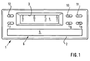
- FIG. 1 shows a tachograph 1 having a flat installation housing, in the front wall 2 of which a recess 3 is formed which serves as a window for the display means of the tachograph 1, for example for an LCD device 4.
- 5 with a bar or a front wall element is designated, which is part of a drawer 6, which is slidably guided in the housing of the tachograph 1.
- 7, 8, 9, 10, 11 and 12 denote buttons, of which 7 and 8 correspond to the rotary knobs which are conventional in conventional tachographs, that is to say with which the working time types break, driving time and other working hours of the driver and front passenger can be set.
- the key 9 enables a menu selection, the keys 10 and 11 are used to scroll forward and backward in the data records of the selected menu. With the button 12, the drawer 6 can be unlocked and the drawer can be pushed forward into an easy-to-reach position.
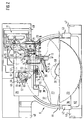
- FIG. 2 shows the drawer 6 with the components required for describing the environment of the innovation and a multi-track registration device 13, which, in the viewing direction chosen in FIG. 2, shows the drawer 6 together with a speed registration device (not shown) below one in the housing of the tachograph 1 attached, not shown mounting board arranged is.
- the multi-track registration device 13 consists essentially of a carriage 14 which is mounted displaceably on a guide rod 15 and is continuously driven in an oscillating manner by means of a motor fastened to the mounting board, which is in geared connection with a rack 16 formed on the carriage 14.
- the slide 14 is operatively connected to a control shaft 19, to which a servomotor (not shown) is assigned, which is connected gearing (arrow A) to a gearwheel 20 fastened on the control shaft 19.
- 21 and 22 designate cams formed on the control shaft 19, one of which, 21, is assigned to the slide 14, the other, 22, to a similar slide of the speed registration device, not shown.
- the cams 21 and 22 serve to pivot the slides on the guide rod 15 and thus to raise and lower the writing pens with respect to the diagram chart 23 above. Of course, all the pens must be lifted when the drawer 6 is to be opened. With the multi-track registration device, lifting is also necessary at least when changing from one registration track to the next.
- an arm formed on the carriage 14 is designated, which carries a pen 25 of the multi-track registration device.
- Another arm 26 formed on the slide 14 serves, as will be explained in more detail below, as a driver, in this function a pin 27 formed on the arm 26 extending through an elongated hole 28 which is formed in a bridge 29 inserted in the drawer 6 .
- the directions of movement of the driver or of the pin 27 are shown symbolically in FIG. 3 with a double arrow B.
- FIG. 2 also shows, the above-mentioned diagram disk 23 is received on a centering and driving mandrel 30 which is driven at the correct time.
- the gearbox mounted in the drawer 6 between the centering and driving mandrel 30 and a motor 31 is only partially shown.
- a diagram 37 located at the bottom, assigned to the passenger in the relevant two-driver device, also on the centering device - And driving mandrel 30 is received and driven by this at the correct time and that the gear connection between the motor 31 and the centering and driving mandrel is located in the bottom of the drawer 6, that is, below the chart 37 below.
- a spacer plate located between the diagram disks 23 and 37 is designated by 38, which on the one hand serves the top of the diagram disk 23 as a registration document and on the other hand serves as a carrier for a registration member 39 recording on the diagram disk below. As shown in FIG.
- the spacer plate 38 is pivotably mounted in the bridge 29 and thus in the drawer 6 in a suitable manner by means of bearing pins 40 and 41 for the purpose of changing the diagram chart 37 below, and is supported, if necessary, by means of molded-on tabs 42 and 43
- a recessed grip 45 formed in the drawer 6 serves to grip the spacer plate 38 and the diagram disks 23, 37, in particular when they are removed. With 46 and 47 6 front contours are used to fix the drawer; 48 and 49 represent guide cheeks provided with suitable slots.
- the diameter of an opening 50 formed in the spacer plate 38 must be selected such that a free rotational movement of the eccentrically designed centering and driving mandrel 30 and an unimpeded pivoting the spacer plate 38 is ensured in any position of the centering and driving mandrel 30.
- a transmission lever forming the gear connection between the multi-track registration device 13 and the registration member 39 is designated, which is arranged in a recess 52 provided in the bridge 29 and to which adjustment means 53 are assigned.
- the coupling between the transmission lever 51 and the registration member 39 is designated 54.
- the bottom view, FIG. 3, illustrates the arrangement of the transmission lever 51 within the recess 52.
- the two-armed transmission lever 51 is rotatable on an axis 55 formed on the bridge 29 and is axially self-locking in that finger-shaped extensions 58 formed on the arms 56 and 57 and 59 engage in a recess 60 or reach behind the bridge 29.
- the transmission lever 51 is brought into its functional position by plugging onto the axis 55 and by pivoting, suitable openings or recesses 61 and 62 having to be provided.
- a spring, designated 63, engaging the arm 56 holds the transmission lever 51 in a basic position in which the arm 57 is supported by means of the finger-shaped extension 58 on an eccentric 64 belonging to the adjusting means 53.
- the eccentric 64 forms, together with a latching and adjusting lever 65, a component which is rotatably mounted on a pin 67 formed on the bottom 66 of the free depression 60.
- the registration member 39 is arranged in a recess 70 formed in the spacer plate 38 and is rotatably mounted on a molded-on pin 71.
- a designated 72, also integrally formed on the spacer plate 38 serves to axially secure the registration member 39 consisting of a lever 73 and a leaf spring 75 embedded in the lever 73 and carrying a pen 74.
- a pen is found on the by means of a suitable holder Leaf spring 75 attached sapphire pin use.
- the coupling 54 provided between the transmission lever 51 and the registration member 39 is designed as a joint and has an axis 76 formed on the lever 73, on which a fork 77 formed on the arm 57 of the transmission lever 51 engages.
- the inner surfaces of the fork legs 78 and 79 are curved or beveled, so that there is a punctiform contact between the axis 76 and the legs of the fork 77.
- a registration element 80 shown in FIG. 4 is designed as a slide, for the storage of which a suitably designed clearance must be provided in the spacer plate 38.
- this exemplary embodiment enables linear diagram elements to be recorded.
- guide beads 81 and 82 are formed on the slide parallel to one another and a leaf spring 83 is attached, for example by ultrasonic welding, to which a suitable recess 84 is assigned in the slide.
- a pen attached to the leaf spring 83 is designated.
- An axis designated 86 represents, in the same way as axis 76, a joint element for engaging the transmission lever 51.
- FIG. 3 three diagrams are shown symbolically, which are recorded by the stylus 74 of the registration element 39 on the diagram disc below, which is not shown in the bottom view shown in FIG. 3.
- the diagrams 88 and 89 mean different types of work and the diagram 90, which is recorded in the aforementioned basic position of the transmission lever 51, means pause.
Landscapes
- Physics & Mathematics (AREA)
- General Physics & Mathematics (AREA)
- Time Recorders, Dirve Recorders, Access Control (AREA)
- Recording Measured Values (AREA)
- Navigation (AREA)
Abstract
Description
Die Erfindung betrifft eine Antriebsverbindung für ein Registrierorgan in einem Fahrtschreiber mit einem flachen Einbaugehäuse, in welchem als Aufzeichnungsträger gleichzeitig zwei gleichachsig angeordnete und mittels einer Schublade zwischen einer Einlege-/Entnahmeposition und einer Registrierposition bewegbare, uhrzeitrichtig angetriebene Diagrammscheiben Anwendung finden, ein auf der untenliegenden Diagrammscheibe zur Aufzeichnung von Balkendiagrammen wirksames Registrierorgan an einer den beiden Diagrammscheiben zugeordneten Distanzplatte gelagert ist und die Distanzplatte zum Wechseln der untenliegenden Diagrammscheibe im Körper der Schublade derart schwenkbar angebracht ist, daß sich die geometrische Achse der Distanzplatte in einer Parallellage zu den Diagrammscheiben befindet.The invention relates to a drive connection for a registration element in a tachograph with a flat installation housing, in which two diagonally arranged diagram disks arranged at the same time and movable by means of a drawer between an insertion / removal position and a registration position and driven at the correct time are used, one on the diagram diagram below effective recording element for recording bar graphs is mounted on a spacer plate assigned to the two graph disks and the spacer plate is pivotably mounted in the drawer body for changing the underlying graph disc in such a way that the geometric axis of the spacer plate is in a parallel position to the graph disks.
Ein derartiger flach konzipierter, als sogenanntes Zweifahrergerät ausgebildeter Fahrtschreiber bereitet erhebliche Schwierigkeiten hinsichtlich der räumlichen Anordnung der Antriebsmittel insbesondere aber der Antriebsverbindungen zu dem Zentrier- und Mitnahmedorn der Diagrammscheiben und den verschiedenen auf den beiden Diagrammscheiben wirksamen Registrierorganen sowie der Verriegelung, Fixierung und Entriegelung der Schublade selbst. Ferner muß ein solcher Fahrtschreiber auf einfache Weise reproduzierbar sein, letzten Endes den Anforderungen der Großserienfertigung genügen und der für die Fahrzeuginstrumentierung ohnehin bestehenden Bedingung eines möglichst geringen Aufwandes gerecht werden, wobei wegen der geforderten Registriergenauigkeit ein relativ hoher Qualitätsstand zu schaffen ist. Das heißt, es sind größere Toleranzadditionen zu vermeiden, Mehrfachnutzungen von Antrieben und Antriebsverbindungen anzustreben und die Anzahl der Bauteile zu reduzieren. Dies gilt insbesondere für die Gestaltung der Antriebsverbindung zu dem auf der untenliegenden Diagrammscheibe wirksamen, räumlich relativ ungüstig gelagerten Registrierorgan.Such a flatly designed tachograph designed as a so-called two-driver device poses considerable difficulties with regard to the spatial arrangement of the drive means, in particular, however, the drive connections to the centering and driving mandrel of the diagram disks and the various registration elements effective on the two diagram disks, as well as the locking, fixing and unlocking of the drawer itself Furthermore, such a tachograph must be reproducible in a simple manner, ultimately satisfy the requirements of large-scale production and meet the existing requirements for vehicle instrumentation with as little effort as possible, whereby a relatively high quality level must be achieved due to the required registration accuracy. That means there are bigger tolerance additions to avoid striving for multiple uses of drives and drive connections and to reduce the number of components. This applies in particular to the design of the drive connection to the registration element, which is effective on the diagram chart below and is relatively spatially unfavorable.
Die Aufgabe der vorliegenden Erfindung bestand somit darin eine Antriebsverbindung für das an der Distanzplatte gelagerte Registrierorgan zu schaffen, welcher den vorstehend genannten, sich zum Teil widersprechenden Bedingungen optimal gerecht wird.The object of the present invention was therefore to provide a drive connection for the registration member mounted on the spacer plate, which optimally meets the above-mentioned, partly contradicting conditions.
Die Lösung der Aufgabe beschreibt der Anspruch 1. Vorteilhafte Ausgestaltungen der Erfindung sind in den Unteransprüchen dargestellt.The solution to the problem is described in
Die gefundene Lösung erfüllt die aufgabengemäß gestellten Anforderungen an die gesuchte Antriebsverbindung in vollem Umfange. Insbesondere bietet sie eine zuverlässige Funktion, die auch bei einer weniger sorgfältigen Handhabung der Distanzplatte beim Wechseln der Diagrammscheiben gewährleistet ist. Der Gedanke den Antrieb des in der Distanzplatte gelagerten und auf der untenliegenden Diagrammscheibe wirksamen Registrierorgans vom Schlitten einer Mehrspurregistriervorrichtung abzugreifen, die der obenliegenden Diagrammscheibe zugeordnet ist, vermeidet einen separaten Antrieb für das in der Distanzplatte gelagerte Registrierorgan und eine erheblich größere Anzahl von Bauelementen in der dann erforderlichen Getriebeverbindung. Hervorzuheben ist ferner, daß innerhalb der Antriebsverbindung kein Versatzproblem auftritt, da ein Einkuppelvorgang beim Verschwenken der Distanzplatte fehlt. Auf der anderen Seite ist die Mitnahmeposition zwischen dem Schlitten der Mehrspurregistriervorrichtung und dem Übertragungshebel relativ genau festgelegt, da der Schlitten in bezug auf die Lage des auf dem Schlitten angeordneten Schreibstiftes zu den auf den Diagrammscheiben aufzuzeichnenden Registrierspuren justiert werden muß und die Schublade, in welcher der Übertragungshebel gelagert ist, beim Schließen mit Mitteln zusammenwirkt, die eine genaue Lagefixierung der Schublade in der Registrierposition ermöglichen.The solution found fully meets the requirements placed on the drive connection in question. In particular, it offers a reliable function that is guaranteed even when the spacer plate is handled with less care when changing the diagram disks. The idea of tapping the drive of the registration element mounted in the spacer plate and effective on the diagram plate below from the slide of a multi-track registration device which is assigned to the diagram plate above avoids a separate drive for the registration element stored in the spacer plate and a considerably larger number of components in the then required gearbox connection. It should also be emphasized that there is no misalignment problem within the drive connection, since there is no engagement process when the spacer plate is pivoted. On the other hand, the driving position between the slide of the multi-track registration device and the transmission lever is determined relatively precisely, since the slide must be adjusted in relation to the position of the stylus arranged on the slide to the registration tracks to be recorded on the diagram disks and the drawer in which the Transmission lever is mounted when closing with means interacts, which allow the drawer to be precisely fixed in the registration position.
Im folgenden sei die Erfindung anhand von Zeichnungen erläutert. Es zeigen:
Figur 1- eine Frontansicht eines die Erfindung beinhaltenden Fahrtschreibers,
Figur 2- eine Draufsicht auf die Schublade des Fahrtschreibers gemäß
Figur 1 mit Freischnitten und mit einer Zuordnung einer Mehrspurregistriervorrichtung, Figur 3- eine bezogen auf die
Figur 2 Untersicht von Distanzplatte und Brücke, - Figur 4
- ein weiteres Ausführungsbeispiel eines der untenliegenden Diagrammscheibe zugeordneten Registrierorgans.
- Figure 1
- 2 shows a front view of a tachograph incorporating the invention,
- Figure 2
- 2 shows a top view of the tachograph drawer according to FIG. 1 with free cuts and with an assignment of a multi-track registration device,
- Figure 3
- a view from below of the spacer plate and bridge,
- Figure 4
- a further embodiment of a registration member assigned to the diagram chart below.
Die Frontansicht, Figur 1, zeigt einen ein flaches Einbaugehäuse aufweisenden Fahrtschreiber 1, in dessen Frontwand 2 eine Aussparung 3 ausgebildet ist, die als Fenster für die Anzeigemittel des Fahrtschreibers 1, beispielsweise für eine LCD-Vorrichtung 4 dient. Mit 5 ist eine Leiste bzw. ein Frontwandelement bezeichnet, welches Teil einer Schublade 6, die in dem Gehäuse des Fahrtschreibers 1 verschiebbar geführt ist, darstellt. 7, 8, 9, 10, 11 und 12 bezeichnen Tasten, von denen 7 und 8 den an sich bei herkömmlichen Fahrtschreibern üblichen Drehknöpfen entsprechen, das heißt, mit denen die Arbeitszeitarten Pause, Lenkzeit und andere Arbeitszeiten von Fahrer und Beifahrer einstellbar sind. Die Taste 9 ermöglicht eine Menüwahl, die Tasten 10 und 11 dienen dem Vor- und Rückwärtsblättern in den Datensätzen des jeweils angewählten Menüs. Mit der Taste 12 kann die Schublade 6 entriegelt und ein Vorschieben der Schublade in eine griffgünstige Position ausgelöst werden.The front view, FIG. 1, shows a
Die Draufsicht, Figur 2, zeigt die Schublade 6 mit den für die Beschreibung des Umfeldes der Neuerung erforderlichen Bauelementen und einer Mehrspurregistriervorrichtung 13, die in der in Figur 2 gewählten Blickrichtung auf die Schublade 6 gemeinsam mit einer nicht dargestellten Geschwindigkeitsregistriervorrichtung unterhalb einer im Gehäuse des Fahrtschreibers 1 befestigten, nicht dargestellten Montageplatine angeordnet ist. Die Mehrspurregistriervorrichtung 13 besteht im wesentlichen aus einem Schlitten 14, welcher auf einer Führungsstange 15 verschiebbar gelagert ist und mittels eines auf der Montageplatine befestigten Motors, der in getrieblicher Verbindung mit einer an dem Schlitten 14 ausgebildeten Zahnstange 16 steht, kontinuierlich oszillierend angetrieben wird. Über einen Arm 17 und eine Schenkelfeder 18 steht der Schlitten 14 mit einer Steuerwelle 19 in Wirkverbindung, welcher ein nicht dargesteller Stellmotor zugeordnet ist, der getrieblich (Pfeil A) mit einem auf der Steuerwelle 19 befestigten Zahnrad 20 verbunden ist. Mit 21 und 22 sind an der Steuerwelle 19 angeformte Nocken bezeichnet, von denen eine, 21, dem Schlitten 14, die andere, 22, einem gleichartigen Schlitten der nicht dargestellten Geschwindigkeitsregistriervorrichtung zugeordnet ist. Die Nocken 21 und 22 dienen dem Verschwenken der Schlitten auf der Führungsstange 15 und bezüglich der obenliegenden Diagrammscheibe 23 somit dem Anheben und Absenken der Schreibstifte. Das Anheben sämtlicher Schreibstifte muß selbstverständlich dann erfolgen, wenn die Schublade 6 geöffnet werden soll. Bei der Mehrspurregistriervorrichtung ist das Anheben außerdem wenigstens beim Wechsel von einer Registrierspur in die nächste erforderllich. Mit 24 ist ein am Schlitten 14 ausgebildeter Arm bezeichnet, der einen Schreibstift 25 der Mehrspurregistriervorrichtung trägt. Ein weiterer am Schlitten 14 angeformter Arm 26 dient, was nachfolgend noch näher erläutert wird, als Mitnehmer, wobei in dieser Funktion ein an dem Arm 26 angeformter Zapfen 27 durch ein Langloch 28 hindurchgreift, welches in einer in der Schublade 6 eingesetzten Brücke 29 ausgebildet ist. Die Bewegungsrichtungen des Mitnehmers bzw. des Zapfens 27 sind in Figur 3 mit einem Doppelpfeil B symbolisch dargestellt.The top view, FIG. 2, shows the
Wie die Figur 2 ferner zeigt, ist die bereits erwähnte obenliegende Diagrammscheibe 23 auf einem Zentrier- und Mitnahmedorn 30 aufgenommen, der uhrzeitrichtig angetrieben wird. Der Übersichtlichkeit halber ist das in der Schublade 6 gelagerte Getriebe zwischen dem Zentrier- und Mitnahmedorn 30 und einem Motor 31 nur teilweise dargestellt. Dabei handelt es sich um ein Zahnrad 32, ein Zahnradpaar 33/34 und ein auf der Welle des Rotors 35 des Motors 31 befestigtes Ritzel 36. Ergänzend sei noch erwähnt, daß eine untenliegende, in dem betreffenden Zweifahrergerät dem Beifahrer zugeordnete Diagrammscheibe 37 ebenfalls auf dem Zentrier- und Mitnahmedorn 30 aufgenommen ist und von diesem uhrzeitrichtig angetrieben wird und daß die getriebliche Verbindung zwischen dem Motor 31 und dem Zentrier- und Mitnahmedorn sich im Boden der Schublade 6, das heißt unterhalb der untenliegenden Diagrammscheibe 37 befindet. Mit 38 ist eine zwischen den Diagrammscheiben 23 und 37 befindliche Distanzplatte bezeichnet, welche einerseits der obenliegenden Diagrammscheibe 23 als Registrierunterlage andererseits einem auf der untenliegenden Diagrammscheibe aufzeichnenden Registrierorgan 39 als Träger dient. Die Distanzplatte 38 ist, wie die Figur 2 zeigt, zum Zwecke des Wechselns der untenliegenden Diagrammscheibe 37 in der Brücke 29 und somit in der Schublade 6 in geeigneter Weise mittels Lagerzapfen 40 und 41 schwenkbar gelagert und stützt sich mittels angeformter Lappen 42 und 43 gegebenenfalls unter Verwendung von Ausrichtstiften und/oder einer lösbaren, ebenfalls dem Ausrichten der Distanzplatte 38 dienenden, nicht näher bezeichneten Fügeverbindung zwischen den Lappen 42, 43 und einem Versteifungsrand 44 der Schublade 6 auf dieser ab. Eine in der Schublade 6 ausgeformte Griffmulde 45 dient dem Greifen der Distanzplatte 38 und der Diagrammscheiben 23, 37 insbesondere bei deren Entnahme. Mit 46 und 47 sind der frontseitigen Fixierung der Schublade 6 dienende Konturen bezeichnet; 48 und 49 stellen mit geeigneten Schlitzen versehene Führungswangen dar. Der Vollständigkeit halber sei noch erwähnt, daß der Durchmesser einer in der Distanzplatte 38 ausgebildeten Öffnung 50 derart gewählt werden muß, daß eine freie Drehbewegung des exzentrisch ausgebildeten Zentrier- und Mitnahmedorns 30 sowie ein ungehindertes Verschwenken der Distanzplatte 38 in jeder Stellung des Zentrier- und Mitnahmedorns 30 gewährleistet ist.As FIG. 2 also shows, the above-mentioned
Mit 51 ist ein die getriebliche Verbindung zwischen der Mehrspurregistriervorrichtung 13 und dem Registrierorgan 39 bildender Übertragungshebel bezeichnet, welcher in einer in der Brücke 29 vorgesehenen Freisenkung 52 angeordnet ist und welchem Justiermittel 53 zugeordnet sind. Die Kupplung zwischen dem Übertragungshebel 51 und dem Registrierorgan 39 ist mit 54 bezeichnet. Die Untersicht, Figur 3, verdeutlicht die Anordnung des Übertragungshebels 51 innerhalb der Freisenkung 52. Dabei ist der zweiarmige Übertragungshebel 51 auf einer an der Brücke 29 angeformten Achse 55 drehbar und axial selbstsichernd dadurch gelagert, daß an den Armen 56 und 57 angeformte fingerförmige Fortsätze 58 und 59 in eine Freisenkung 60 eingreifen bzw. die Brücke 29 hintergreifen. Bei der Montage wird der Übertragungshebel 51 durch Aufstecken auf die Achse 55 und durch Verschwenken in seine Funktionsstellung gebracht, wobei geeignete Durchbrüche oder Senkungen 61 und 62 vorgesehen sein müssen. Eine mit 63 bezeichnete, am Arm 56 angreifende Feder hält den Übertragungshebel 51 in einer Grundstellung, in der sich der Arm 57 mittels des fingerförmigen Fortsatzes 58 auf einem zu den Justiermitteln 53 gehörenden Exzenter 64 abstützt. Der Exzenter 64 bildet zusammen mit einem Rast- und Stellhebel 65 ein Bauteil, welches auf einem am Boden 66 der Freisenkung 60 angeformten Zapfen 67 drehbar gelagert ist. Mit 68 ist ein auf dem Boden 66 der Freisenkung 60 aufbauendes mit einer Rastverzahnung versehenes Zahnsegment bezeichnet, mit welchem der Rast- und Stellhebel 65, der in geeigneter Weise gestuft und mit einer Kerbe versehen ausgebildet ist, zusammenwirkt. Das freie Ende des Rast- und Stellhebels 65 greift durch eine schlitzförmige, in den Figuren 2 und 3 sichtbare Öffnung, die bei der spritzgießtechnischen Bildung der Freisenkung 60 und einer dieser zugeordneten bogenförmigen Vertiefung 69 automatisch entsteht, auf die Unterseite der Brücke 29 durch, so daß der Exzenter 64 ebenso wie der Übertragungshebel 51 selbssichernd auf dem Zapfen 67 gelagert ist. Der Vollständigkeit halber sei erwähnt, daß die beschriebenen Justiermittel, der Einstellung der Lage des Armes 56 in Bezug auf den mitnehmenden Zapfen 27 dienen.With 51 a transmission lever forming the gear connection between the
Wie aus der Figur 3 ferner noch hervorgeht ist das Registrierorgan 39 in einer in der Distanzplatte 38 ausgebildeten Vertiefung 70 angeodnet, und auf einem angeformten Stift 71 drehbar gelagert. Ein mit 72 bezeichneter, ebenfalls an der Distanzplatte 38 angeformter Rasthacken dient der axialen Sicherung des aus einem Hebel 73 und einer in dem Hebel 73 eingebetteten, einen Schreibstift 74 tragende Blattfeder 75 bestehenden Registrierorgans 39. Vorzugsweise findet als Schreibstift ein mittels einer geeigneten Fassung an der Blattfeder 75 befestigter Saphirstift Verwendung. Die zwischen dem Übertragungshebel 51 und dem Registrierorgan 39 vorgesehen Kupplung 54 ist als Gelenk ausgebildet und weist eine an dem Hebel 73 angeformte Achse 76 auf, an welcher eine am Arm 57 des Übertragungshebels 51 ausgebildete Gabel 77 angreift. Um wegen ungleicher Hebellängen ein Kippen der Gabel 77 auf der Achse 76 zu ermöglichen sind die Innenflächen der Gabelschenkel 78 und 79 gewölbt oder angeschrägt ausgebildet, so daß sich jeweils eine punkförmige Berührung zwischen der Achse 76 und den Schenkeln der Gabel 77 ergibt.As can also be seen from FIG. 3, the
Das mit der Figur 4 dargestellte weitere Ausführungsbeispiel eines Registrierorgans 80 ist als Schieber ausgebildet, zu dessen Lagerung eine entsprechend gestaltete Freisparung in der Distanzplatte 38 vorgesehen werden muß. Dieses Ausführungsbeispiel ermöglicht im Gegensatz zum vorstehend beschriebenen Ausführungsbeispiel das Aufzeichnen geradliniger Diagrammelemente. Im Einzelnen sind an dem Schieber parallel zueinander Führungswülste 81 und 82 ausgebildet und zum Beispiel durch Ultraschallschweißen eine Blattfeder 83 befestigt, welcher in dem Schieber eine geeignete Vertiefung 84 zugeordnet ist. Mit 85 ist ein an der Blattfeder 83 befestigter Schreibstift bezeichnet. Eine mit 86 bezeichnete Achse stellt in gleicher Weise wie die Achse 76 ein Gelenkelement für das Einkuppeln des Übertragungshebels 51 dar.The further exemplary embodiment of a
In Figur 3 sind symbolisch drei Diagramme dargestellt, die vom Schreibstift 74 des Registrierorgans 39 auf der untenliegenden Diagrammscheibe, die in der in Figur 3 dargestellten Untersicht nicht gezeichnet ist, aufgezeichnet werden. Dabei bedeuten die Diagramme 88 und 89 unterschiedliche Arbeitsarten und das Diagramm 90, das in der erwähnten Grundstellung des Übertragungshebels 51 aufgezeichnet wird, Pause.In FIG. 3, three diagrams are shown symbolically, which are recorded by the
Claims (6)
dadurch gekennzeichnet,
characterized by
dadurch gekennzeichnet,
characterized by
dadurch gekennzeichnet,
characterized by
dadurch gekennzeichnet,
characterized by
dadurch gekennzeichnet,
characterized by
dadurch gekennzeichnet,
characterized by
Applications Claiming Priority (2)
| Application Number | Priority Date | Filing Date | Title |
|---|---|---|---|
| DE19613872 | 1996-04-06 | ||
| DE19613872A DE19613872A1 (en) | 1996-04-06 | 1996-04-06 | Drive connection for a registration element in a tachograph |
Publications (3)
| Publication Number | Publication Date |
|---|---|
| EP0800151A2 true EP0800151A2 (en) | 1997-10-08 |
| EP0800151A3 EP0800151A3 (en) | 1999-05-19 |
| EP0800151B1 EP0800151B1 (en) | 2005-05-25 |
Family
ID=7790700
Family Applications (1)
| Application Number | Title | Priority Date | Filing Date |
|---|---|---|---|
| EP97104665A Expired - Lifetime EP0800151B1 (en) | 1996-04-06 | 1997-03-19 | Drive connection for a tachograph registering device |
Country Status (3)
| Country | Link |
|---|---|
| EP (1) | EP0800151B1 (en) |
| JP (1) | JP3958825B2 (en) |
| DE (2) | DE19613872A1 (en) |
Cited By (3)
| Publication number | Priority date | Publication date | Assignee | Title |
|---|---|---|---|---|
| EP1024349A1 (en) * | 1999-01-30 | 2000-08-02 | Mannesmann VDO Aktiengesellschaft | Registering device, particularly for a tachograph |
| CN109147087A (en) * | 2018-07-06 | 2019-01-04 | 广州番客信息科技有限公司 | A kind of automobile data recorder with air purification function |
| CN110493991A (en) * | 2019-08-28 | 2019-11-22 | 郭宏凯 | A kind of multifunctional running recorder |
Families Citing this family (3)
| Publication number | Priority date | Publication date | Assignee | Title |
|---|---|---|---|---|
| DE29621117U1 (en) * | 1996-12-05 | 1997-01-23 | Vdo Schindling | Adjustment device for the drive connection of a recording element recording bar charts |
| US7318593B2 (en) * | 2004-10-15 | 2008-01-15 | Ford Global Technologies, Llc | Stabilizer bar and bushing assembly |
| KR102077483B1 (en) | 2019-05-24 | 2020-02-14 | 박태수 | Detachable module for glasses |
Citations (5)
| Publication number | Priority date | Publication date | Assignee | Title |
|---|---|---|---|---|
| GB1417366A (en) * | 1973-04-14 | 1975-12-10 | Kienzle Apparate Gmbh | Support for a recording means in a tachograph |
| EP0309854A2 (en) * | 1987-09-30 | 1989-04-05 | Mannesmann Kienzle GmbH (HR B1220) | Recorder with a flat housing |
| EP0328454A1 (en) * | 1988-02-10 | 1989-08-16 | Jaeger | Inscription device for a recorder with two diagram discs |
| DE9317101U1 (en) * | 1993-11-09 | 1994-03-03 | Mannesmann Kienzle Gmbh | Motor vehicle with a tachograph |
| EP0709683A1 (en) * | 1994-10-31 | 1996-05-01 | Mannesmann Kienzle GmbH | Arrangement of recording media in a tachograph with a flat housing |
-
1996
- 1996-04-06 DE DE19613872A patent/DE19613872A1/en not_active Withdrawn
-
1997
- 1997-03-19 DE DE59712323T patent/DE59712323D1/en not_active Expired - Lifetime
- 1997-03-19 EP EP97104665A patent/EP0800151B1/en not_active Expired - Lifetime
- 1997-04-07 JP JP08794797A patent/JP3958825B2/en not_active Expired - Fee Related
Patent Citations (5)
| Publication number | Priority date | Publication date | Assignee | Title |
|---|---|---|---|---|
| GB1417366A (en) * | 1973-04-14 | 1975-12-10 | Kienzle Apparate Gmbh | Support for a recording means in a tachograph |
| EP0309854A2 (en) * | 1987-09-30 | 1989-04-05 | Mannesmann Kienzle GmbH (HR B1220) | Recorder with a flat housing |
| EP0328454A1 (en) * | 1988-02-10 | 1989-08-16 | Jaeger | Inscription device for a recorder with two diagram discs |
| DE9317101U1 (en) * | 1993-11-09 | 1994-03-03 | Mannesmann Kienzle Gmbh | Motor vehicle with a tachograph |
| EP0709683A1 (en) * | 1994-10-31 | 1996-05-01 | Mannesmann Kienzle GmbH | Arrangement of recording media in a tachograph with a flat housing |
Cited By (3)
| Publication number | Priority date | Publication date | Assignee | Title |
|---|---|---|---|---|
| EP1024349A1 (en) * | 1999-01-30 | 2000-08-02 | Mannesmann VDO Aktiengesellschaft | Registering device, particularly for a tachograph |
| CN109147087A (en) * | 2018-07-06 | 2019-01-04 | 广州番客信息科技有限公司 | A kind of automobile data recorder with air purification function |
| CN110493991A (en) * | 2019-08-28 | 2019-11-22 | 郭宏凯 | A kind of multifunctional running recorder |
Also Published As
| Publication number | Publication date |
|---|---|
| JP3958825B2 (en) | 2007-08-15 |
| DE59712323D1 (en) | 2005-06-30 |
| EP0800151A3 (en) | 1999-05-19 |
| DE19613872A1 (en) | 1997-10-09 |
| EP0800151B1 (en) | 2005-05-25 |
| JPH1030937A (en) | 1998-02-03 |
Similar Documents
| Publication | Publication Date | Title |
|---|---|---|
| EP0110349B1 (en) | Arrangement for positioning a magnetic head on several tape tracks | |
| DE60316834T2 (en) | Electronic device | |
| EP0012223B1 (en) | Tachograph | |
| DE2455142A1 (en) | MODULAR SERVO TRACK RECORDER WITH LINEAR POSITION ADJUSTMENT | |
| EP0800151A2 (en) | Drive connection for a tachograph registering device | |
| DE2707363B2 (en) | Device for inserting and ejecting cassettes for magnetic tape recorders | |
| EP0864137B1 (en) | Tachograph with drawer | |
| EP0247550B1 (en) | Tachograph for motor vehicles | |
| EP0126374B1 (en) | Registering device for a tachograph | |
| EP0339225A2 (en) | Device for a recording apparatus | |
| EP1127700B1 (en) | Printing device and method with movable print head guiding means | |
| DE2706022A1 (en) | ADJUSTMENT DEVICE FOR A VEHICLE REAR MIRROR | |
| EP0330002B1 (en) | Arrangement for the automatic, exactly timed positioning of a bundle of diagram discs for registration in portions, yet continuously | |
| EP0368219B1 (en) | Tachograph with time-dependently driven interaction means for diagram discs serving as record carriers | |
| DE19732583A1 (en) | Flat data card holder | |
| DE2208714C3 (en) | Registration arrangement for tachographs | |
| DE2604127A1 (en) | DIAGRAM DISC DRIVE ARRANGEMENT FOR A TACHOGRAPHER | |
| EP1024349B1 (en) | Registering device, particularly for a tachograph | |
| EP0744714B1 (en) | Recording device for tachograph | |
| EP0265595B1 (en) | Disposition for driving a record chart | |
| EP1057960A2 (en) | Actuating device | |
| DE19546029C2 (en) | Tachograph with a writing system for speed records | |
| DE1817340C3 (en) | Registration arrangement for tachographs | |
| DE3242140A1 (en) | ASSEMBLY PROCEDURE FOR A TELEPHONE'S PEN | |
| DE3935870C1 (en) | Car side window drive - has drive pinion meshing with segment drive output element swivelling between end settings |
Legal Events
| Date | Code | Title | Description |
|---|---|---|---|
| PUAI | Public reference made under article 153(3) epc to a published international application that has entered the european phase |
Free format text: ORIGINAL CODE: 0009012 |
|
| AK | Designated contracting states |
Kind code of ref document: A2 Designated state(s): CH DE FR GB IT LI |
|
| RAP1 | Party data changed (applicant data changed or rights of an application transferred) |
Owner name: MANNESMANN VDO AG |
|
| 17P | Request for examination filed |
Effective date: 19981205 |
|
| PUAL | Search report despatched |
Free format text: ORIGINAL CODE: 0009013 |
|
| AK | Designated contracting states |
Kind code of ref document: A3 Designated state(s): CH DE FR GB IT LI |
|
| RAP1 | Party data changed (applicant data changed or rights of an application transferred) |
Owner name: SIEMENS AKTIENGESELLSCHAFT |
|
| 17Q | First examination report despatched |
Effective date: 20021022 |
|
| GRAP | Despatch of communication of intention to grant a patent |
Free format text: ORIGINAL CODE: EPIDOSNIGR1 |
|
| GRAS | Grant fee paid |
Free format text: ORIGINAL CODE: EPIDOSNIGR3 |
|
| GRAA | (expected) grant |
Free format text: ORIGINAL CODE: 0009210 |
|
| AK | Designated contracting states |
Kind code of ref document: B1 Designated state(s): CH DE FR GB IT LI |
|
| REG | Reference to a national code |
Ref country code: GB Ref legal event code: FG4D Free format text: NOT ENGLISH |
|
| REG | Reference to a national code |
Ref country code: CH Ref legal event code: EP |
|
| REF | Corresponds to: |
Ref document number: 59712323 Country of ref document: DE Date of ref document: 20050630 Kind code of ref document: P |
|
| GBT | Gb: translation of ep patent filed (gb section 77(6)(a)/1977) |
Effective date: 20050719 |
|
| PG25 | Lapsed in a contracting state [announced via postgrant information from national office to epo] |
Ref country code: LI Free format text: LAPSE BECAUSE OF NON-PAYMENT OF DUE FEES Effective date: 20060331 Ref country code: CH Free format text: LAPSE BECAUSE OF NON-PAYMENT OF DUE FEES Effective date: 20060331 |
|
| PLBE | No opposition filed within time limit |
Free format text: ORIGINAL CODE: 0009261 |
|
| STAA | Information on the status of an ep patent application or granted ep patent |
Free format text: STATUS: NO OPPOSITION FILED WITHIN TIME LIMIT |
|
| ET | Fr: translation filed | ||
| 26N | No opposition filed |
Effective date: 20060228 |
|
| REG | Reference to a national code |
Ref country code: CH Ref legal event code: PL |
|
| PGFP | Annual fee paid to national office [announced via postgrant information from national office to epo] |
Ref country code: GB Payment date: 20090325 Year of fee payment: 13 |
|
| PGFP | Annual fee paid to national office [announced via postgrant information from national office to epo] |
Ref country code: IT Payment date: 20090324 Year of fee payment: 13 |
|
| PGFP | Annual fee paid to national office [announced via postgrant information from national office to epo] |
Ref country code: FR Payment date: 20090312 Year of fee payment: 13 |
|
| GBPC | Gb: european patent ceased through non-payment of renewal fee |
Effective date: 20100319 |
|
| REG | Reference to a national code |
Ref country code: FR Ref legal event code: ST Effective date: 20101130 |
|
| PG25 | Lapsed in a contracting state [announced via postgrant information from national office to epo] |
Ref country code: FR Free format text: LAPSE BECAUSE OF NON-PAYMENT OF DUE FEES Effective date: 20100331 |
|
| PG25 | Lapsed in a contracting state [announced via postgrant information from national office to epo] |
Ref country code: GB Free format text: LAPSE BECAUSE OF NON-PAYMENT OF DUE FEES Effective date: 20100319 Ref country code: IT Free format text: LAPSE BECAUSE OF NON-PAYMENT OF DUE FEES Effective date: 20100319 |
|
| PGFP | Annual fee paid to national office [announced via postgrant information from national office to epo] |
Ref country code: DE Payment date: 20140331 Year of fee payment: 18 |
|
| REG | Reference to a national code |
Ref country code: DE Ref legal event code: R119 Ref document number: 59712323 Country of ref document: DE |
|
| PG25 | Lapsed in a contracting state [announced via postgrant information from national office to epo] |
Ref country code: DE Free format text: LAPSE BECAUSE OF NON-PAYMENT OF DUE FEES Effective date: 20151001 |