EP0798552A1 - Photoacoustic gas sensor - Google Patents
Photoacoustic gas sensor Download PDFInfo
- Publication number
- EP0798552A1 EP0798552A1 EP97104373A EP97104373A EP0798552A1 EP 0798552 A1 EP0798552 A1 EP 0798552A1 EP 97104373 A EP97104373 A EP 97104373A EP 97104373 A EP97104373 A EP 97104373A EP 0798552 A1 EP0798552 A1 EP 0798552A1
- Authority
- EP
- European Patent Office
- Prior art keywords
- microphone
- gas sensor
- monitoring
- heating element
- signal
- Prior art date
- Legal status (The legal status is an assumption and is not a legal conclusion. Google has not performed a legal analysis and makes no representation as to the accuracy of the status listed.)
- Granted
Links
Images


Classifications
-
- G—PHYSICS
- G01—MEASURING; TESTING
- G01N—INVESTIGATING OR ANALYSING MATERIALS BY DETERMINING THEIR CHEMICAL OR PHYSICAL PROPERTIES
- G01N21/00—Investigating or analysing materials by the use of optical means, i.e. using sub-millimetre waves, infrared, visible or ultraviolet light
- G01N21/17—Systems in which incident light is modified in accordance with the properties of the material investigated
- G01N21/1702—Systems in which incident light is modified in accordance with the properties of the material investigated with opto-acoustic detection, e.g. for gases or analysing solids
Definitions
- the invention relates to a photoacoustic gas sensor with an explosion-proof, active device for monitoring the functionality of its components and calibration of its sensitivity, and a method for evaluating the output signals of the device.
- Photoacoustic gas sensors are used in research and industry to determine the concentration of certain predominant gases. Their areas of application are, for example, the monitoring of processes in bioreactors or breweries and of gas concentrations in laboratories and other work rooms in order to maintain the maximum workplace concentrations (MAK). They determine the presence and concentration of a gas and emit an alarm or warning signal when a predetermined concentration is exceeded.
- MAK maximum workplace concentrations
- Photoacoustic gas sensors used today typically consist of a measuring cell with a gas-permeable membrane, a pulsed light source, a photodiode, a microphone and an electrical circuit for operating the light source and the microphone and for Evaluation of the microphone output signal.
- the light source sends light pulses into the measuring cell that have a wavelength that are absorbed by the gas to be detected.
- narrowband light sources such as light emitting diodes and lasers
- broadband light sources such as incandescent filaments are used together with an optical bandpass filter.
- the photodiode is used to measure the intensity of the light pulses, the signals resulting from it being used to regulate the operating voltage of the light source and to maintain a stable light intensity. If a gas to be detected is in the vicinity of the gas sensor, it penetrates through the gas-permeable membrane into the measuring cell and absorbs the incident light there. The absorption of the light pulses causes the gas in the measuring cell to heat up and expand, producing pressure modulation which is received by the microphone and converted into an electrical signal. The output signal of the microphone is amplified by an evaluation circuit and compared with gas concentration values which were stored in an EEPROM when the sensor was calibrated. The concentration of the detected gas is determined on the basis of the stored calibration values and, if necessary, a warning or alarm signal is issued.
- the gas sensor of the above-mentioned application has a passive monitoring of the functionality of the microphone and other of its components by means of a background signal of the microphone output signal, which results from the heating of parts of the measuring cell by light absorption. If the microphone is defective or the membrane has a small hole, the background signal becomes smaller. However, the method does not allow to determine whether the microphone is still fully sensitive or whether its sensitivity has dropped. If the sensitivity of the microphone has dropped, for example due to drift over a longer period of time or due to a sudden defect, its initial values are assigned to incorrect gas concentrations and a gas alarm may not be reported.
- the background signal is of different sizes depending on the wavelength of the light pulses that reach the measuring cell and, at certain wavelengths, is almost zero, which makes evaluation of the background signal difficult.
- Another method is to monitor the noise of the microphone. If this noise disappears, this is an indication that the microphone is no longer working properly. On the other hand, the presence of noise is not a clear indication of an intact microphone.
- a microphone noise is pretended when the membrane is also defective and a noise is caused by external pressure fluctuations, which is superimposed on the greatly reduced noise of the defective microphone. A defect in the membrane and in the microphone can therefore be misinterpreted.
- these monitoring methods based on background signal and noise are based on passive effects that are not controlled directly by the circuit.
- the object of the invention is to provide a photoacoustic gas sensor of the type mentioned above, which has an active device for monitoring the functionality of the gas-permeable membrane and the microphone, and a method for evaluating the output signals of the monitoring device for detection the functional state of the microphone and the membrane and for calibration of the microphone sensitivity and a method for operating the monitoring device.
- the operation of this monitoring device should be explosion-proof.
- a photoacoustic gas sensor of the type mentioned above which contains a device for monitoring the functionality of the microphone and the membrane and carrying out a calibration of the microphone sensitivity, the device for actively generating an artificial pressure modulation in the measuring cell, which is carried out by the microphone electrical monitoring signals are converted, and has a circuit for operating this device, for processing and evaluating the monitoring signals and calibrating the microphone sensitivity.
- This device preferably consists of an electrical heating element for modulated heating of the air, such as a wire, a resistor, a heating foil.
- the microphone housing is also suitable for this heating.
- the modulated heating of the air, provided that the membrane does not leak has, an artificial pressure modulation generated, which does not result from the presence of a gas in the measuring cell of the gas sensor.
- the microphone If the microphone is also functional, it generates an electrical signal when the pressure modulation is received, which is amplified and evaluated by the circuit.
- the functionality of the membrane and the microphone is inferred on the basis of the resulting monitoring signal and, if necessary, calibration of the microphone sensitivity is carried out, the size and the temporal change in the monitoring signal being evaluated.
- the size of the resulting monitoring signal is assigned to one of several different areas. If the size of the monitoring signal falls within a predetermined positive range, the circuit emits a message which indicates that both the membrane and the microphone are functioning correctly. If the monitoring signal falls in a higher or lower range compared to the first predetermined range, a microprocessor calibrates the microphone sensitivity by recalculating the gas concentration values based on the determined microphone sensitivity and storing them in an EEPROM.
- the circuit issues a fault message, which indicates that either there is no pressure modulation in the measuring cell due to a leaky membrane, the sensitivity of the microphone has dropped to zero and / or the heating element is defective is.
- the explosion protection of the monitoring device is guaranteed by the fact that the current flowing through the heating element and the maximum temperatures reached by the heating element and the components of the circuit meet safety requirements, such as those according to the Euronorm EN 50020: 1994, which are approved by the Physikalische Technische Bundesweg Braunschweig ( PTB) are checked.
- the wire as a heating element, this is achieved through a suitable choice of the material and the dimensions of the wire.
- Figure 1 shows a photoacoustic gas sensor in cross section with a device for heating the air in the measuring cell.
- Figures 2 a) and b) show an embodiment of an electrical heating element for heating the air in the measuring cell and the assembly of an electrically heatable wire as a heating element.
- FIG. 3 shows a schematic structure of the circuit for operating the monitoring device of the gas sensor and evaluating the output signals of the microphone.
- FIG. 4 shows an example of a time profile for monitoring the gas sensor and calibrating the microphone sensitivity.
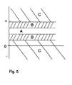
- FIG. 5 shows the various areas to which the monitoring signals are assigned for the purpose of their evaluation.
- Figure 1 shows a photoacoustic gas sensor 1 in cross section with a measuring cell 2, a lamp 3 with a filament 4 as a light source and an optical bandpass filter 5, a microphone 6 and a gas permeable membrane 7, which lies on a perforated grid 8 and with adhesive with the measuring cell wall is tightly connected.
- a photodiode for monitoring the light intensity is not shown here.
- Broadband light pulses emanate from the filament 4 and, after spectral filtering at the bandpass filter 5, emit the measuring cell 2.
- the optical bandpass filter 5 is transparent in a narrow spectral range around the wavelength of 4.26 ⁇ m, which is absorbed by CO 2 gas.
- the gas sensor 1 has a heating element 9 which is arranged at any location in the interior of the measuring cell 2. It is preferably in the vicinity of the printed circuit board 10 with the circuit 11 for operating the gas sensor 1 and heating element 9 and for evaluating the output signals of the microphone 6.
- the heating element 9 preferably consists of a thin wire, although conventional and surface-mount Resistors and heating foils are suitable for this.
- Another embodiment of the device for heating the air is the electrical heating of the microphone housing.
- a modulated voltage is applied to the heating element 9, whereby it itself and the air in the measuring cell 2 are heated and the expansion of the air produces an artificial pressure modulation which is independent of the presence of gases to be detected.
- This pressure modulation is converted by the microphone 6 into an electrical signal, which is amplified and evaluated by the circuit 11, whereupon a message is issued which indicates whether the microphone 6 and the membrane 7 are working or the microphone sensitivity compared to the beginning of the operating time of the Gas sensor 1 has changed.
- the heating element 9 and the components of the circuit 11 and their operating parameters meet the requirements for explosion-proof operation according to the PTB.
- a heating element 9 with a corresponding resistance is therefore used, and if a wire is used, its diameter, length and material are matched to this resistance.
- the material is preferably one that is chemically stable and whose resistance changes as little as possible as a function of temperature, so that the heat output emitted by the wire is stable over a long period and is independent of the temperature. Examples of suitable materials are Nikrothal and Konstantan. If a material with a higher temperature coefficient of specific resistance is used instead, the choice of the parameters of the wire would be more difficult, since the voltage applied to the heating element would have to be regulated according to the wire temperature.
- a heating element that meets the above-mentioned conditions is a wire made of nikrothal with a diameter of 30 ⁇ m and a length of 1 cm, the resistance of which is 20 ⁇ . If a current of 0.6 mA flows through this wire at an applied voltage of 12 mV, it heats up by 2.5 ° C according to theoretical calculations, while the measured temperature increase of the wire is approx. 1 ° C.
- the parameters and the material of the wire can also be selected accordingly, so that only the requirements of temperature class T4 are met.
- FIGS. 2 a) and b) show in a cross section or a plan view an example of an assembly of a wire 12 as a heating element 9.
- the wire 12 is fastened on a cylindrical support 13 which is attached to the microphone 6 and fastened to the printed circuit board 10 with adhesive is.
- the microphone 6 is fastened on a shoulder.
- the cylindrical support also serves as a holder for the microphone 6.
- the wire is guided in a notch 14, so that it runs on the plane shown with the dashed line and does not move from it.
- the purpose of this is that there is an air space under and above the wire 12 and it is electrically insulated by not coming into contact with the wall of the measuring cell 2 and the microphone.
- the cylindrical support 13 is made of a non-conductive material, such as polycarbonate.
- the wire 12 is wound like a meander around several slots 15 on the upper edge of the cylindrical carrier 13. The ends of the wire 12 are guided through holes in the center of the cylindrical carrier 13 and soldered to solder points 16 on the printed circuit board 10.
- Figure 3 shows a schematic structure of the gas sensor 1 with monitoring device. It shows the electrical components of the gas sensor 1, the lamp L 3, the microphone M 6, the photodiode PD 17 and the heating element HE 9 and the circuit 11 for operating the gas sensor 1 and the monitoring device.
- the circuit 11 contains a first driver circuit 18 for the heating element 9 and a second driver circuit 19 for the lamp L 3.
- the electrical signals generated by the microphone M 6 on the basis of received pressure modulations are fed to an evaluation circuit 20, where they are linearly amplified by a high-pass filter. and low-pass filter cleaned and synchronized rectified and smoothed by a phase-sensitive rectifier will.
- the resulting DC signals are forwarded to a MP 21 microprocessor, which compares them with predetermined comparison values.
- the microprocessor MP 21 includes the change in the monitoring signal over time in the evaluation. In the case of a slow change, such as a change over several days, this is assessed as a long-term drift, and the microphone sensitivity is calibrated by tracking the values stored in the EEPROM 22 to determine the concentration values or gas concentration values in accordance with the change in the microphone sensitivity. This is done by determining the percentage change in the monitoring signals and changing the gas concentration values accordingly. This tracking of the microphone sensitivity corrects the long-term drift of the microphone.
- the microprocessor issues a message, for example an optical or acoustic signal which indicates a fault on the microphone and / or on the membrane indicates.
- the EEPROM 22 contains further operating data of the gas sensor such as counters, temperatures of the measuring gas, brightness values of the lamp 3 and phase values for the optimal amplification of the microphone signals.
- the temperatures of the measurement gas are determined by a temperature sensor contained in the microprocessor 20 and used by the microprocessor 21 for the recalculation of the temperature-dependent gas concentration values.
- the brightness values of the lamp 3 are fed from the photodiode 17 and the evaluation circuit 20 to the microprocessor 21 and used for regulating the light intensity of the lamp 3 by calculating the necessary pulse duration and feeding the driver circuit 19 for the lamp 3.
- the phase values are the phase differences between the voltage signal for the heating element 9 and the output signal of the microphone 6.
- the phase values are determined during the manufacture of the gas sensor 1 by optimizing the amplification of the output signal of the microphone 6 by entering the phase.
- the phase at which the microphone signal reaches a maximum is then stored in the EEPROM 22.
- the EEPROM 22 is a serial EEPROM with an integrated interface circuit bus (IIC bus). Thanks to this IIC bus, only one data line is required in addition to the clock line.
- the clock of the EEPROM also serves as a clock for the heating element 9 in that the clock signal is fed to the first driver circuit 18 for the heating element 9.
- FIG. 4 shows an example of a time profile of a monitoring of the gas sensor 1 as a function of the time t.
- Figure 4 a) shows the voltage pulses V (L) for the operation of the lamp 3. For example, it is operated at 14 Hz and a duty cycle of one third.
- a heating element for Heating of the measuring cell 2 is, as the modulated voltage V (HE) in Figure 4 b) show, operated at 7 Hz, the power curve having the clock frequency of 14 Hz.
- the voltage V (L) also serves to trigger the phase-sensitive rectifier of the evaluation circuit 20.
- a synchronization of the lamp 3 and the heating of the heating element 9 allows a simpler evaluation of the monitoring signals and gas signals with the same electrical components.
- the modulated voltage preferably has a sine function; a triangular or trapezoidal function or a function with any flanks are also suitable.
- FIG. 4 c) shows the approximate temperature curve T (HE) of a nicotine wire 2.5 cm long and 30 ⁇ m in diameter, through which a current of less than 1 mA flows according to FIG. 4 b).
- FIG. 4 d) shows a microphone signal V (M) generated by the microphone 6, in this case the monitoring signal resulting from the artificial heating of the measuring cell 2.
- the phase shift ⁇ of the generated signal with respect to the voltage for operating the lamp 3 is the phase determined during production by optimization of the microphone signal and stored in the EEPROM 22.
- microphone signals that are caused by the presence of detectable gases in the measuring cell are also amplified with this phase shift ⁇ .
- Figure 4 e shows the DC output signal Vout of the evaluation circuit 20 of the monitoring device over a long period of time.
- the monitoring device is switched on and off at a frequency of 1/10 Hz, which prevents the monitoring device from being in permanent operation.
- the monitoring signal is in each case an order of magnitude smaller than the signal that results from gas detection. It can therefore be distinguished with certainty from a gas alarm signal.
- the mean value of the signal difference D between the on and off state is determined. This mean value is the decisive variable of the monitoring signal and is assigned by the microprocessor 21 to the areas in FIG. 5.
- a preferred embodiment of the photoacoustic gas sensor has small dimensions.
- gas sensors of this type there is a problem of electrical crosstalk between the components, while in larger photoacoustic measuring devices these problems arise less because the components can be placed further apart there.
- the heating element is located very close to the microphone in a small gas sensor.
- the heating element and the microphone are connected to the same supply in order to save electrical components. This often causes electrical crosstalk between the heating element and the microphone, which causes interference signals on the microphone signal V (M).
- the operation of the photoacoustic gas sensor is similar to that shown in FIG. 4, but with an additional phase shift in the voltage for operating the heating element V (HE) and the resulting temperature profile T (HE) in FIGS.
- the voltage for the lamp V (L) in turn serves to trigger the phase-sensitive rectifier for the amplification of the microphone signal V (M).
- the microphone signal V (M) is amplified with the phase shift ⁇ with respect to V (L) in order to optimize the signal strength.
- the heating voltage for the heating element V (HE) is now shifted in its phase with respect to the microphone signal V (M).
- the phase shift is determined experimentally so that the electrical crosstalk drops to a minimum value. While the voltage for the heating element V (HE) is out of phase with respect to the microphone signal V (M), the monitoring signal artificially produced by the heating element is approximately in phase with the microphone signal V (M).
- thermal inertia of the wire for the heating element that has been specially selected for this application.
- the thermal inertia is chosen experimentally such that the temperature rise T (HE) and thus also the artificially produced monitoring signal is approximately in phase with the microphone signal V (M). If, for example, the monitoring signal and the microphone signal V (M) are only out of phase by 30 °, the electrical crosstalk is zero, the monitoring signal reaching 85% of its maximum value.
- the monitoring signal is interpreted in accordance with the logic table below and a message is issued. If the mean value of the signal difference D falls within the range A, the normal signal size has been reached through an intact membrane and with full microphone sensitivity, and a message is issued by the microprocessor, indicating that the membrane and the microphone are functioning correctly. If the mean falls into one of the two areas B and changes only slowly over a longer period of time, a recalibration is carried out to adjust the microphone sensitivity. On the other hand, if the change over time is rapid, it is not due to a long-term drift, but to a defect, and a fault message is issued.
Abstract
Description
Die Erfindung betrifft einen photoakustischen Gassensor mit einer explosionssicher betriebenen, aktiven Vorrichtung zur Überwachung der Funktionstüchtigkeit seiner Komponenten und Kalibrierung seiner Empfindlichkeit und ein Verfahren zur Bewertung der Ausgangssignale der Vorrichtung.The invention relates to a photoacoustic gas sensor with an explosion-proof, active device for monitoring the functionality of its components and calibration of its sensitivity, and a method for evaluating the output signals of the device.
Photoakustische Gassensoren werden in Forschung und Industrie zur Feststellung der Konzentration von bestimmten vorherrschenden Gasen eingesetzt. Ihre Anwendungsbereiche sind zum Beispiel die Überwachung von Prozessen in Bioreaktoren oder Brauereien und von Gaskonzentrationen in Laboratorien und anderen Arbeitsräumen zwecks Einhaltung der maximalen Arbeitsplatzkonzentrationen (MAK). Sie stellen die Anwesenheit und Konzentration eines Gases fest und geben bei Überschreiten einer vorgegebenen Konzentration ein Alarm- oder Warnsignal ab.Photoacoustic gas sensors are used in research and industry to determine the concentration of certain predominant gases. Their areas of application are, for example, the monitoring of processes in bioreactors or breweries and of gas concentrations in laboratories and other work rooms in order to maintain the maximum workplace concentrations (MAK). They determine the presence and concentration of a gas and emit an alarm or warning signal when a predetermined concentration is exceeded.
Heute verwendete photoakustische Gassensoren, wie zum Beispiel in der Europäischen Patentanmeldung Nr. 95113854.4 beschrieben, bestehen typischerweise aus einer Messzelle mit einer gaspermeablen Membran, einer gepulst betriebenen Lichtquelle, einer Photodiode, einem Mikrofon und einer elektrischen Schaltung zum Betrieb der Lichtquelle und des Mikrofons und zur Auswertung des Mikrofonausgangssignals. Die Lichtquelle sendet Lichtpulse in die Messzelle, die eine Wellenlänge besitzen, die von dem zu detektierenden Gas absorbiert werden. Hierzu werden entweder schmalbandige Lichtquellen wie Leuchtdioden und Laser oder breitbandige Lichtquellen wie Glühwendel zusammen mit einem optischen Bandpassfilter eingesetzt. Die Photodiode dient dazu, die Intensität der Lichtpulse zu messen, wobei die von ihr resultierenden Signale der Regulierung der Betriebsspannung der Lichtquelle und Einhaltung einer stabilen Lichtintensität dienen. Befindet sich ein zu detektierendes Gas in der Umgebung des Gassensors, dringt es durch die gaspermeable Membran in die Messzelle ein und absorbiert dort das eingestrahlte Licht. Die Absorption der Lichtpulse bewirkt eine Erwärmung und Ausdehnung des Gases in der Messzelle, wodurch eine Druckmodulierung erzeugt wird, die vom Mikrofon empfangen und in ein elektrisches Signal umgewandelt wird. Das Ausgangssignal des Mikrofons wird von einer Auswerteschaltung verstärkt und mit Gaskonzentrationswerten verglichen, die bei einer Eichung des Sensors in einem EEPROM gespeichert worden sind. Aufgrund der gespeicherten Eichwerte wird die Konzentration des detektierten Gases bestimmt und gegebenenfalls ein Warn- oder Alarmsignal abgegeben.Photoacoustic gas sensors used today, as described for example in European Patent Application No. 95113854.4, typically consist of a measuring cell with a gas-permeable membrane, a pulsed light source, a photodiode, a microphone and an electrical circuit for operating the light source and the microphone and for Evaluation of the microphone output signal. The light source sends light pulses into the measuring cell that have a wavelength that are absorbed by the gas to be detected. For this purpose, either narrowband light sources such as light emitting diodes and lasers or broadband light sources such as incandescent filaments are used together with an optical bandpass filter. The photodiode is used to measure the intensity of the light pulses, the signals resulting from it being used to regulate the operating voltage of the light source and to maintain a stable light intensity. If a gas to be detected is in the vicinity of the gas sensor, it penetrates through the gas-permeable membrane into the measuring cell and absorbs the incident light there. The absorption of the light pulses causes the gas in the measuring cell to heat up and expand, producing pressure modulation which is received by the microphone and converted into an electrical signal. The output signal of the microphone is amplified by an evaluation circuit and compared with gas concentration values which were stored in an EEPROM when the sensor was calibrated. The concentration of the detected gas is determined on the basis of the stored calibration values and, if necessary, a warning or alarm signal is issued.
Ist das Ausgangssignal solcher Gassensoren gleich Null, besteht die Unsicherheit, ob dieses Nullsignal einer Abwesenheit des zu detektierenden Gases entspricht oder einem Defekt an einer seiner Komponenten zugrunde liegt, wie zum Beispiel einem Abfall der Mikrofonempfindlichkeit.If the output signal of such gas sensors is zero, there is uncertainty as to whether this zero signal corresponds to an absence of the gas to be detected or is due to a defect in one of its components, such as a drop in microphone sensitivity.
Der Gassensor der oben erwähnten Anmeldeschrift verfügt über eine passive Überwachung der Funktionstüchtigkeit des Mikrofons und anderer seiner Komponenten mittels eines Untergrundsignals des Mikrofonausgangssignals, das von der Erwärmung von Teilen der Messzelle durch Lichtabsorption herrührt. Ist das Mikrofon defekt oder hat die Membran ein kleines Loch, so wird das Untergrundsignal kleiner. Die Methode erlaubt jedoch nicht, festzustellen, ob das Mikrofon noch über seine volle Empfindlichkeit verfügt oder seine Empfindlichkeit abgefallen ist. Ist nämlich die Empfindlichkeit des Mikrofons gefallen, wie zum Beispiel durch Drift über längere Zeit oder durch einen plötzlich auftretenden Defekt, werden seine Ausgangswerte falschen Gaskonzentrationen zugeordnet und ein Gasalarm wird womöglich nicht gemeldet. Ferner ist das Untergrundsignal in Abhängigkeit der Wellenlänge der Lichtpulse, die in die Messzelle gelangen, verschieden gross und bei bestimmten Wellenlängen sogar nahezu gleich Null, wodurch eine Auswertung des Untergrundsignals erschwert ist. Eine weitere Methode ist die Überwachung des Rauschens des Mikrofons. Verschwindet dieses Rauschen, ist dies ein Hinweis darauf, dass das Mikrofon nicht mehr richtig arbeitet. Andererseits ist ein Vorhandensein eines Rauschens kein eindeutiger Hinweis auf ein intaktes Mikrofon. Ein Mikrofonrauschen wird nämlich dann vorgetäuscht, wenn die Membran ebenfalls defekt ist und ein Rauschen durch äussere Druckschwankungen verursacht wird, welches das stark verkleinerte Rauschen des defekten Mikrofons überlagert. Ein Defekt an der Membran und am Mikrofon kann also falsch interpretiert werden. Schliesslich beruhen diese Überwachungsmethoden mittels Untergrundsignal und Rauschen auf passiven Effekten, die von der Schaltung nicht direkt gesteuert werden.The gas sensor of the above-mentioned application has a passive monitoring of the functionality of the microphone and other of its components by means of a background signal of the microphone output signal, which results from the heating of parts of the measuring cell by light absorption. If the microphone is defective or the membrane has a small hole, the background signal becomes smaller. However, the method does not allow to determine whether the microphone is still fully sensitive or whether its sensitivity has dropped. If the sensitivity of the microphone has dropped, for example due to drift over a longer period of time or due to a sudden defect, its initial values are assigned to incorrect gas concentrations and a gas alarm may not be reported. Furthermore, the background signal is of different sizes depending on the wavelength of the light pulses that reach the measuring cell and, at certain wavelengths, is almost zero, which makes evaluation of the background signal difficult. Another method is to monitor the noise of the microphone. If this noise disappears, this is an indication that the microphone is no longer working properly. On the other hand, the presence of noise is not a clear indication of an intact microphone. A microphone noise is pretended when the membrane is also defective and a noise is caused by external pressure fluctuations, which is superimposed on the greatly reduced noise of the defective microphone. A defect in the membrane and in the microphone can therefore be misinterpreted. Finally, these monitoring methods based on background signal and noise are based on passive effects that are not controlled directly by the circuit.
Von diesem Stand der Technik ausgehend, ist der Erfindung die Aufgabe gestellt, einen photoakustischen Gassensor der obengenannten Art zu schaffen, der eine aktive Vorrichtung zur Überwachung der Funktionstüchtigkeit der gaspermeablen Membran und des Mikrofons aufweist, sowie ein Verfahren zur Bewertung der Ausgangssignale der Überwachungsvorrichtung zur Feststellung des Funktionszustands des Mikrofons und der Membran und zur Kalibrierung der Mikrofonempfindlichkeit und ein Verfahren zum Betrieb der Überwachungsvorrichtung. Insbesondere soll der Betrieb dieser Überwachungsvorrichtung explosionssicher sein.Starting from this prior art, the object of the invention is to provide a photoacoustic gas sensor of the type mentioned above, which has an active device for monitoring the functionality of the gas-permeable membrane and the microphone, and a method for evaluating the output signals of the monitoring device for detection the functional state of the microphone and the membrane and for calibration of the microphone sensitivity and a method for operating the monitoring device. In particular, the operation of this monitoring device should be explosion-proof.
Die Aufgabe wird erfindungsgemäss durch einen photoakustischen Gassensor der obengenannten Art gelöst, der eine Vorrichtung zur Überwachung der Funktionstüchtigkeit des Mikrofons und der Membran und Durchführung einer Kalibrierung der Mikrofonempfindlichkeit enthält, die eine Vorrichtung zur aktiven Erzeugung einer künstlichen Druckmodulierung in der Messzelle, die vom Mikrofon in elektrische Überwachungssignale umgewandelt werden, sowie eine Schaltung zum Betrieb dieser Vorrichtung, zur Verarbeitung und Auswertung der Überwachungssignale und Kalibrierung der Mikrofonempfindlichkeit aufweist. Vorzugsweise besteht diese Vorrichtung aus einem elektrischen Heizelement zur modulierten Erwärmung der Luft, wie zum Beispiel ein Draht, ein Widerstand, eine Heizfolie. Es eignet sich auch das Mikrofongehäuse zu dieser Erwärmung. Durch die modulierte Erwärmung der Luft wird, sofern die Membran keine undichten Stellen aufweist, eine künstliche Druckmodulierung erzeugt, die nicht von der Anwesenheit eines Gases in der Messzelle des Gassensors herrührt. Ist das Mikrofon ebenfalls funktionstüchtig, erzeugt es bei Empfang der Druckmodulierung ein elektrisches Signal, das von der Schaltung verstärkt und ausgewertet wird.The object is achieved according to the invention by a photoacoustic gas sensor of the type mentioned above, which contains a device for monitoring the functionality of the microphone and the membrane and carrying out a calibration of the microphone sensitivity, the device for actively generating an artificial pressure modulation in the measuring cell, which is carried out by the microphone electrical monitoring signals are converted, and has a circuit for operating this device, for processing and evaluating the monitoring signals and calibrating the microphone sensitivity. This device preferably consists of an electrical heating element for modulated heating of the air, such as a wire, a resistor, a heating foil. The microphone housing is also suitable for this heating. The modulated heating of the air, provided that the membrane does not leak has, an artificial pressure modulation generated, which does not result from the presence of a gas in the measuring cell of the gas sensor. If the microphone is also functional, it generates an electrical signal when the pressure modulation is received, which is amplified and evaluated by the circuit.
In dem erfindungsgemässen Verfahren wird aufgrund des resultierenden Überwachungssignals auf die Funktionstüchtigkeit der Membran und des Mikrofons geschlossen und gegebenenfalls eine Kalibrierung der Mikrofonempfindlichkeit durchgeführt, wobei die Grösse sowie die zeitliche Veränderung des Überwachungssignals ausgewertet werden. In dem Verfahren wird die Grösse des resultierenden Überwachungssignals einem von mehreren, verschiedenen Bereichen zugeordnet. Fällt die Grösse des Überwachungssignals in einen vorgegebenen positiven Bereich, gibt die Schaltung eine Meldung ab, die darauf hinweist, dass sowohl die Membran als auch das Mikrofon richtig funktionieren. Fällt das Überwachungssignals im Vergleich zum ersten vorgegebenen Bereich in einen höheren oder tieferen Bereich, wird von einem Mikroprozessor eine Kalibrierung der Mikrofonempfindlichkeit durchgeführt, indem aufgrund der festgestellten Mikrofonempfindlichkeit die Gaskonzentrationswerte neu berechnet werden und in einem EEPROM abgespeichert werden. Werden andererseits vorgegebene Schwellenwerte vom Überwachungssignal entweder über- oder unterschritten, gibt die Schaltung eine Störungsmeldung ab, die darauf hinweist, dass entweder durch eine undichte Membran keine Druckmodulierung in der Messzelle entstanden ist, die Empfindlichkeit des Mikrofons auf Null abgefallen und/oder das Heizelement defekt ist.In the method according to the invention, the functionality of the membrane and the microphone is inferred on the basis of the resulting monitoring signal and, if necessary, calibration of the microphone sensitivity is carried out, the size and the temporal change in the monitoring signal being evaluated. In the method, the size of the resulting monitoring signal is assigned to one of several different areas. If the size of the monitoring signal falls within a predetermined positive range, the circuit emits a message which indicates that both the membrane and the microphone are functioning correctly. If the monitoring signal falls in a higher or lower range compared to the first predetermined range, a microprocessor calibrates the microphone sensitivity by recalculating the gas concentration values based on the determined microphone sensitivity and storing them in an EEPROM. If, on the other hand, the monitoring signal either exceeds or falls below predetermined threshold values, the circuit issues a fault message, which indicates that either there is no pressure modulation in the measuring cell due to a leaky membrane, the sensitivity of the microphone has dropped to zero and / or the heating element is defective is.
Die Explosionssicherheit der Überwachungsvorrichtung ist dadurch gewährleistet, dass der durch das Heizelement fliessende Strom und die von dem Heizelement und den Komponenten der Schaltung erreichten Höchsttemperaturen Sicherheitsvoraussetzungen erfüllen, wie zum Beispiel jene gemäss der Euronorm EN 50020:1994, die von der Physikalischen Technischen Bundesanstalt Braunschweig (PTB) überprüft werden. Am Beispiel des Drahtes als Heizelement ist dies durch geeignete Wahl des Materials und der Dimensionen des Drahtes realisiert.The explosion protection of the monitoring device is guaranteed by the fact that the current flowing through the heating element and the maximum temperatures reached by the heating element and the components of the circuit meet safety requirements, such as those according to the Euronorm EN 50020: 1994, which are approved by the Physikalische Technische Bundesanstalt Braunschweig ( PTB) are checked. Using the example of the wire as a heating element, this is achieved through a suitable choice of the material and the dimensions of the wire.
Ausführungsformen der Erfindung sind anhand der folgenden Zeichnungen erläutert.Embodiments of the invention are explained with reference to the following drawings.
Figur 1 zeigt einen photoakustischen Gassensor im Querschnitt mit einer Vorrichtung zur Erwärmung der Luft in der Messzelle.Figure 1 shows a photoacoustic gas sensor in cross section with a device for heating the air in the measuring cell.
Figuren 2 a) und b) zeigen eine Ausführung eines elektrischen Heizelementes zur Erwärmung der Luft in der Messzelle und der Montage eines elektrisch heizbaren Drahtes als Heizelement.Figures 2 a) and b) show an embodiment of an electrical heating element for heating the air in the measuring cell and the assembly of an electrically heatable wire as a heating element.
Figur 3 zeigt einen schematischen Aufbau der Schaltung zum Betrieb der Überwachungsvorrichtung des Gassensors und Auswertung der Ausgangssignale des Mikrofons.FIG. 3 shows a schematic structure of the circuit for operating the monitoring device of the gas sensor and evaluating the output signals of the microphone.
Figur 4 zeigt ein Beispiel eines zeitlichen Verlaufs einer Überwachung des Gassensors und Kalibrierung der Mikrofonempfindlichkeit.FIG. 4 shows an example of a time profile for monitoring the gas sensor and calibrating the microphone sensitivity.
Figur 5 zeigt die verschiedenen Bereiche, denen die Überwachungssignale zwecks ihrer Bewertung zugeordnet werden.FIG. 5 shows the various areas to which the monitoring signals are assigned for the purpose of their evaluation.
Figur 1 zeigt einen photoakustischen Gassensor 1 im Querschnitt mit einer Messzelle 2, einer Lampe 3 mit einem Glühwendel 4 als Lichtquelle und einem optischen Bandpassfilter 5, einem Mikrofon 6 und einer gaspermeablen Membran 7, die auf einem Lochgitter 8 liegt und mit Klebstoff mit der Messzellwand dicht verbunden ist. (Eine Photodiode zur Überwachung der Lichtintensität ist hier nicht eingezeichnet). Vom Glühwendel 4 gehen breitbandige Lichtpulse aus, die nach einer spektralen Filterung am Bandpassfilter 5 die Messzelle 2 ausstrahlen. Beispielsweise ist das optische Bandpassfilter 5 in einem schmalen Spektralbereich um die Wellenlänge von 4.26 µm durchlässig, das von CO2-Gas absorbiert wird. Befindet sich CO2-Gas in der Umgebung des Gassensors 1, dringt es durch die gaspermeable Membran 7 in die Messzelle 2 ein, wo es das Licht absorbiert und sich erwärmt. Durch die Erwärmung dehnt es sich aus und erzeugt eine Druckmodulierung, die vom Mikrofon 6 in ein elektrisches Signal umgewandelt wird. Zur Überwachung der Funktion der Membran 7 und des Mikrofons 6 weist der Gassensor 1 ein Heizelement 9 auf, das an einem beliebigen Ort im Innenraum der Messzelle 2 angeordnet ist. Vorzugsweise ist es in der Nähe der Leiterplatte 10 mit der Schaltung 11 zum Betrieb des Gassensors 1 und Heizelements 9 sowie zur Auswertung der Ausgangssignale des Mikrofons 6. Das Heizelement 9 besteht vorzugsweise aus einem dünnen Draht, wobei sich aber auch konventionelle und Surface-Mount-Widerstände sowie Heizfolien dafür eignen. Eine weitere Ausführung der Vorrichtung der Erwärmung der Luft ist die elektrische Erwärmung des Mikrofongehäuses. An das Heizelement 9 wird eine modulierte Spannung angelegt, wodurch es selbst und die Luft in der Messzelle 2 erwärmt werden und durch die Ausdehnung der Luft eine künstliche und von der Anwesenheit von zu detektierenden Gasen unabhängige Druckmodulierung erzeugt wird. Diese Druckmodulierung wird vom Mikrofon 6 in ein elektrisches Signal umgewandelt, das von der Schaltung 11 verstärkt und ausgewertet wird, worauf eine Meldung abgegeben wird, die angibt, ob das Mikrofon 6 und die Membran 7 funktionieren oder die Mikrofonempfindlichkeit im Vergleich zum Beginn der Einsatzzeit des Gassensors 1 sich verändert hat. Das Heizelement 9 und die Komponenten der Schaltung 11 sowie ihre Betriebsparameter erfüllen die Bestimmungen für einen explosionssicheren Betrieb gemäss des PTB. Diese Bestimmungen, zum Beispiel die der Temperaturklassen T6 und T4 der Euronorm EN 50020:1994, setzen die Maximaltemperatur von Komponenten bei 85°C bzw. 135°C fest. Um eine Zündfähigkeit im Falle eines Defekts des Heizelements auszuschliessen, muss auch der Strom und die Spannung begrenzt werden. Die Strombegrenzung für das Heizelement liegt hier bei 1 mA. Die Bestimmungen für die Temperaturklasse T6 werden von der Überwachungsvorrichtung des Gassensors eingehalten; die Höchsttemperatur des Heizelementes 9 beträgt weniger als 85°C, und mit dem begrenzten Stromfluss von 1 mA wird eine für die Überwachung genügende Erwärmung der Luft erzielt. Hierbei wird die höchste Betriebstemperatur des Gassensors 1 berücksichtigt: Beträgt diese 60°C, darf sich das Heizelement 9 um nicht mehr als 25°C erwärmen. Es wird also ein Heizelement 9 mit entsprechendem Widerstand eingesetzt und bei Verwendung eines Drahtes sind dessen Durchmesser, Länge und Material auf diesen Widerstand abgestimmt. Das Material ist vorzugsweise eines, das chemisch stabil ist und dessen Widerstand sich als Funktion der Temperatur möglichst wenig verändert, sodass die vom Draht abgegebene Wärmeleistung über lange Zeit stabil und unabhängig von der Temperatur sind. Beispiele geeigneter Materialien sind Nikrothal und Konstantan. Wird stattdessen ein Material mit höherem Temperaturkoeffizienten des spezifischen Widerstands eingesetzt, wäre die Wahl der Parameter des Drahtes erschwert, da die am Heizelement angelegte Spannung entsprechend der Drahttemperatur reguliert werden müssten. Ein Beispiel eines Heizelementes, das den genannten Rahmenbedingungen genügt, ist ein Draht aus Nikrothal mit einem Durchmesser von 30 µm und einer Länge von 1 cm, dessen Widerstand 20 Ω beträgt. Fliesst ein Strom von 0.6 mA bei einer angelegten Spannung von 12 mV durch diesen Draht, erwärmt er sich nach theoretischer Berechnung um 2.5°C, während die gemessene Temperaturerhöhung des Drahtes ca. 1°C beträgt. Die Parameter und das Material des Drahtes können auch entsprechend gewählt werden, sodass nur die Bestimmungen der Temperaturklasse T4 erfüllt sind.Figure 1 shows a
Figuren 2 a) und b) zeigen in einem Querschnitt bzw. einer Draufsicht ein Beispiel einer Montage eines Drahtes 12 als Heizelement 9. Der Draht 12 ist auf einem zylindrischen Träger 13 befestigt, der am Mikrofon 6 angefügt und mit Klebstoff an der Leiterplatte 10 befestigt ist. Um einen Luftraum zwischen dem Mikrofon 6 und dem Draht 12 zu gewähren ist das Mikrofon 6 auf einem Absatz befestigt. Dadurch dient der zylindrische Träger zugleich als Halterung für das Mikrofon 6. An der Aussenseite des zylindrischen Trägers 13 ist der Draht in einer Kerbe 14 geführt, sodass sich dieser auf der mit der gestrichelten Linie eingezeichneten Ebene verläuft und sich von ihr nicht verschiebt. Dies bezweckt, dass unter sowie über dem Draht 12 ein Luftraum besteht und er elektrisch isoliert ist, indem er mit der Wand der Messzelle 2 und dem Mikrofon nicht in Kontakt kommt. Der zylindrische Träger 13 besteht aus einem nicht leitenden Material, wie zum Beispiel Polycarbonat. Der Draht 12 ist gleich einem Mäander um mehrere Schlitze 15 am oberen Rand des zylindrischen Trägers 13 gewunden. Die Enden des Drahtes 12 sind durch Löcher in der Mitte des zylindrischen Trägers 13 geführt und mit Lötstellen 16 auf der Leiterplatte 10 verlötet.FIGS. 2 a) and b) show in a cross section or a plan view an example of an assembly of a
Figur 3 zeigt einen schematischen Aufbau des Gassensors 1 mit Überwachungsvorrichtung. Sie zeigt die elektrischen Komponenten des Gassensors 1, die Lampe L 3, das Mikrofon M 6, die Photodiode PD 17 und das Heizelement HE 9 sowie die Schaltung 11 zum Betrieb des Gassensors 1 und der Überwachungsvorrichtung. Die Schaltung 11 enthält eine erste Treiberschaltung 18 für das Heizelement 9 und eine zweite Treiberschaltung 19 für die Lampe L 3. Die vom Mikrofon M 6 aufgrund von empfangenen Druckmodulierungen erzeugten elektrischen Signale werden einer Auswerteschaltung 20 zugeführt, wo sie linear verstärkt, durch ein Hochpass- und Tiefpassfilter bereinigt und durch einen phasenempfindlichen Gleichrichter synchron gleichgerichtet und geglättet werden. Die resultierenden DC-Signale werden an einen Mikroprozessor MP 21 weitergeleitet, der sie mit vorgegebenen Vergleichswerten vergleicht. Fallen die Grössen der Überwachungssignale in vorgegebene Kalibrationsbereiche (siehe hierzu auch Fig. 5), bedeutet dies, dass die Mikrofonempfindlichkeit sich verändert hat. In diesem Fall wird vom Mikroprozessor MP 21 die zeitliche Veränderung des Überwachungssignals in der Bewertung einbezogen. Bei einer langsamen Veränderung, wie zum Beispiel einer Veränderung über mehrere Tage, wird dies als Langzeitdrift bewertet, und es wird eine Kalibrierung der Mikrofonempfindlichkeit durchgeführt, indem die im EEPROM 22 gespeicherten Werte zur Bestimmung der Konzentrationswerte oder Gaskonzentrationswerte entsprechend der Veränderung der Mikrofonempfindlichkeit nachgeführt werden. Dies geschieht, indem die prozentuale Veränderung der Überwachungssignale bestimmt wird und die Gaskonzentrationswerte entsprechend geändert werden. Mit dieser Nachführung der Mikrofonempfindlichkeit wird die Langzeitdrift des Mikrofons korrigiert. Bei einer schnellen Veränderung innerhalb der Kalibrationsbereiche sowie in dem Fall, dass die Überwachungssignale die Kalibrationsbereiche unter- oder überschreiten, wird vom Mikroprozessor eine Meldung abgegeben, wie zum Beispiel ein optisches oder akustisches Signal, das auf eine Störung am Mikrofon und/oder an der Membran hinweist.Figure 3 shows a schematic structure of the
Das EEPROM 22 enthält ausser den Gaskonzentrationswerten weitere Betriebsdaten des Gassensors wie Zähler, Temperaturen des Messgases, Helligkeitswerte der Lampe 3 und Phasenwerte für die optimale Verstärkung der Mikrofonsignale. Die Temperaturen des Messgases werden durch einen im Mikroprozessor 20 enthaltenen Temperaturfühler festgestellt und für die Neuberechnung der temperaturabhängigen Gaskonzentrationswerte durch den Mikroprozessor 21 verwendet. Die Helligkeitswerte der Lampe 3 werden von der Photodiode 17 und der Auswerteschaltung 20 dem Mikroprozessor 21 zugeführt und für die Regelung der Lichtintensität der Lampe 3 verwendet, indem die nötige Impulsdauer berechnet und der Treiberschaltung 19 für die Lampe 3 zugeführt wird. Die Phasenwerte sind die Phasenunterschiede zwischen Spannungssignal für das Heizelement 9 und dem Ausgangssignal des Mikrofons 6. Die Phasenwerte werden während der Herstellung des Gassensors 1 bestimmt, indem die Verstärkung des Ausgangssignals des Mikrofons 6 durch Eingabe der Phase optimiert wird. Die Phase, bei der das Mikrofonsignal ein Maximum erreicht, wird sodann im EEPROM 22 gespeichert.In addition to the gas concentration values, the
Das EEPROM 22 ist ein serielles EEPROM mit einem Integrated Interface Circuit-Bus (IIC-Bus). Dank diesem IIC-Bus ist nebst der Clockleitung nur eine Datenleitung nötig. Die Clock des EEPROMs dient zugleich als Clock für das Heizelement 9, indem das Clocksignal der ersten Treiberschaltung 18 für das Heizelement 9 zugeführt wird.The
Figur 4 zeigt ein Beispiel eines zeitlichen Verlaufs einer Überwachung des Gassensors 1 als Funktion der Zeit t. Figur 4 a) zeigt die Spannungspulse V(L) für den Betrieb der Lampe 3. Beispielsweise wird sie bei 14 Hz und einem Arbeitszyklus von einem Drittel betrieben. Ein Heizelement zur Erwärmung der Messzelle 2 wird, wie die modulierte Spannung V(HE) in Figur 4 b) zeigen, bei 7 Hz betrieben , wobei die Leistungskurve die Taktfrequenz von 14 Hz hat. Die Spannung V(L) dient zugleich auch zum Triggern des phasenempfindlichen Gleichrichters der Auswerteschaltung 20. Eine Synchronisation der Lampe 3 und der Erwärmung des Heizelementes 9 erlaubt eine einfachere Auswertung der Überwachungssignale und Gassignale mit denselben elektrischen Komponenten. Die modulierte Spannung hat aus Gründen des elektrischen Übersprechens vorzugsweise eine Sinusfunktion; eine Dreiecks- oder Trapezfunktion oder eine Funktion mit beliebigen Flanken eignen sich ebenfalls. Figur 4 c) zeigt den ungefähren Temperaturverlauf T(HE) eines Nikrothaldrahts von 2.5 cm Lange und 30 µm im Durchmesser, durch den gemäss Figur 4 b) ein Strom von weniger als 1 mA fliesst. Figur 4 d) zeigt ein vom Mikrofon 6 erzeugtes Mikrofonsignal V(M), in diesem Fall das von der künstlichen Erwärmung der Messzelle 2 resultierende Überwachungssignal. Die Phasenverschiebung Δφ des erzeugten Signals bezüglich der Spannung zum Betrieb der Lampe 3 ist die bei der Herstellung durch Optimierung des Mikrofonsignals festgestellte und im EEPROM 22 gespeicherte Phase. Selbstverständlich werden Mikrofonsignale, die durch die Anwesenheit von detektierbaren Gasen in der Messzelle herbeigeführt werden, ebenfalls mit dieser Phasenverschiebung Δφ verstärkt.FIG. 4 shows an example of a time profile of a monitoring of the
Figur 4 e) zeigt das DC-Ausgangssignal Vout der Auswerteschaltung 20 der Überwachungsvorrichtung über längere Zeit. An diesem Betriebsbeispiel wird die Überwachungsvorrichtung bei einer Frequenz von 1/10 Hz ein- und ausgeschaltet, wodurch vermieden wird, dass die Überwachungsvorrichtung permanent in Betrieb ist. Das Überwachungssignal ist jeweils um eine Grössenordnung kleiner als das Signal, das von einer Gasdetektion herrührt. Es kann also mit Sicherheit von einem Gasalarmsignal unterschieden werden. Über eine gegebene Zeitdauer, zum Beispiel 30 Sekunden, wird der Mittelwert der Signaldifferenz D zwischen dem ein- und ausgeschalteten Zustand bestimmt. Dieser Mittelwert ist die massgebende Grösse des Überwachungssignals und wird vom Mikroprozessor 21 den Bereichen in Fig. 5 zugeordnet.Figure 4 e) shows the DC output signal Vout of the
Aus Platz- und Kostengründen besitzt eine bevorzugte Ausführung des photoakustischen Gassensors kleine Dimensionen. In Gassensoren dieser Art ergibt sich ein Problem des elektrischen Übersprechens zwischen den Komponenten wänrend in grösseren photoakustischen Messgeräten diese Probleme weniger entstehen, da die Komponenten dort weiter auseinander plaziert werden können. In einem kleinen Gassensor ist das Heizelement sehr nahe dem Mikrofon angeordnet. Zusätzlich sind das Heizelement und das Mikrofon zwecks Einsparung von elektrischen Komponenten mit derselben Speisung verbunden. Dies verursacht oft ein elektrisches Übersprechen zwischen dem Heizelement und dem Mikrofon, das Störsignale auf dem Mikrofonsignal V(M) bewirkt. Der Betrieb des photoakustischen Gassensors verläuft ähnlich wie in Figur 4 dargestellt, jedoch mit einer zusätzlichen Phasenverschiebung der Spannung zum Betrieb des Heizelements V(HE) und des resultierenden Temperaturverlaufs T(HE) in den Figuren 4 b) und c). Die Spannung für die Lampe V(L) dient wiederum zum Triggern des phasenempfindlichen Gleichrichters für die Verstärkung des Mikrofonsignals V(M). Dabei wird das Mikrofonsignal V(M) zwecks Optimierung der Signalstärke mit der Phasenverschiebung Δφ bezüglich V(L) verstärkt. Um den elektrischen Einfluss der Heizspannung auf das Mikrofon auf ein Minimum zu reduzieren, wird nun die Heizspannung für das Heizelement V(HE) in Bezug auf das Mikrofonsignal V(M) in seiner Phase verschoben. Die Phasenverschiebung wird dabei experimentell so bestimmt, dass das elektrische Übersprechen auf einen Minimalwert fällt. Während die Spannung für das Heizelement V(HE) in Bezug auf das Mikrofonsignal V(M) phasenverschoben ist, ist das durch das Heizelement künstlich herbeigeführte Überwachungssignal mit dem Mikrofonsignal V(M) annähernd in Phase. Dies wird durch eine speziell für diese Anwendung gewählte thermische Trägheit des Drahtes für das Heizelement herbeigeführt. Die thermische Trägheit wird hierzu experimentell so gewählt, dass der Temperaturanstieg T(HE) und somit auch das künstlich herbeigeführte Überwachungssignal annähernd in Phase ist mit dem Mikrofonsignal V(M). Sind beispielsweise das Überwachungssignal und das Mikrofonsignal V(M) nur noch um 30° ausser Phase, ist das elektrische Übersprechen gleich Null, wobei das Überwachungssignal 85% seines Maximalwerts erreicht.For reasons of space and cost, a preferred embodiment of the photoacoustic gas sensor has small dimensions. In gas sensors of this type, there is a problem of electrical crosstalk between the components, while in larger photoacoustic measuring devices these problems arise less because the components can be placed further apart there. The heating element is located very close to the microphone in a small gas sensor. In addition, the heating element and the microphone are connected to the same supply in order to save electrical components. This often causes electrical crosstalk between the heating element and the microphone, which causes interference signals on the microphone signal V (M). The operation of the photoacoustic gas sensor is similar to that shown in FIG. 4, but with an additional phase shift in the voltage for operating the heating element V (HE) and the resulting temperature profile T (HE) in FIGS. 4 b) and c). The voltage for the lamp V (L) in turn serves to trigger the phase-sensitive rectifier for the amplification of the microphone signal V (M). The microphone signal V (M) is amplified with the phase shift Δφ with respect to V (L) in order to optimize the signal strength. In order to reduce the electrical influence of the heating voltage on the microphone to a minimum, the heating voltage for the heating element V (HE) is now shifted in its phase with respect to the microphone signal V (M). The phase shift is determined experimentally so that the electrical crosstalk drops to a minimum value. While the voltage for the heating element V (HE) is out of phase with respect to the microphone signal V (M), the monitoring signal artificially produced by the heating element is approximately in phase with the microphone signal V (M). This is brought about by a thermal inertia of the wire for the heating element that has been specially selected for this application. For this purpose, the thermal inertia is chosen experimentally such that the temperature rise T (HE) and thus also the artificially produced monitoring signal is approximately in phase with the microphone signal V (M). If, for example, the monitoring signal and the microphone signal V (M) are only out of phase by 30 °, the electrical crosstalk is zero, the monitoring signal reaching 85% of its maximum value.
Fig. 5 zeigt drei verschiedene Bereiche A, B und C. Je nach dem Bereich, in weichen der Mittelwert fällt, wird das Überwachungssignal gemäss der nachfolgenden Logiktabelle interpretiert und eine Meldung abgegeben. Fällt der Mittelwert der Signaldifferenz D in den Bereich A, ist durch eine intakte Membran und bei voller Mikrofonempfindlichkeit der normale Signalgrösse erreicht worden, und es wird vom Mikroprozessor eine Meldung abgegeben, die darauf hinweist, dass die Membran und das Mikrofon korrekt funktionieren. Fällt der Mittelwert in einen der beiden Bereiche B und verändert sich nur langsam über längere Zeit, wird eine Neukalibrierung zur Nachführung der Mikrofonempfindlichkeit durchgeführt. Ist die zeitliche Veränderung dagegen schnell, liegt diese nicht einer Langzeitdrift sondern einem Defekt zugrunde, und es erfolgt eine Störungsmeldung. Fällt der Mittelwert in die Bereiche C, liegt die Mikrofonempfindlichkeit ausserhalb des nachführbaren Bereichs und es wird sowohl bei einer schnellen als auch langsamen zeitlichen Veränderung eine Störungsmeldung abgegeben.
Claims (12)
Priority Applications (1)
| Application Number | Priority Date | Filing Date | Title |
|---|---|---|---|
| EP19970104373 EP0798552B1 (en) | 1996-03-25 | 1997-03-14 | Photoacoustic gas sensor |
Applications Claiming Priority (3)
| Application Number | Priority Date | Filing Date | Title |
|---|---|---|---|
| EP96104689A EP0801296A1 (en) | 1996-03-25 | 1996-03-25 | Photoacoustic gas sensor |
| EP96104689 | 1996-03-25 | ||
| EP19970104373 EP0798552B1 (en) | 1996-03-25 | 1997-03-14 | Photoacoustic gas sensor |
Publications (2)
| Publication Number | Publication Date |
|---|---|
| EP0798552A1 true EP0798552A1 (en) | 1997-10-01 |
| EP0798552B1 EP0798552B1 (en) | 2004-06-02 |
Family
ID=26141823
Family Applications (1)
| Application Number | Title | Priority Date | Filing Date |
|---|---|---|---|
| EP19970104373 Expired - Lifetime EP0798552B1 (en) | 1996-03-25 | 1997-03-14 | Photoacoustic gas sensor |
Country Status (1)
| Country | Link |
|---|---|
| EP (1) | EP0798552B1 (en) |
Cited By (2)
| Publication number | Priority date | Publication date | Assignee | Title |
|---|---|---|---|---|
| US6006585A (en) * | 1997-01-25 | 1999-12-28 | Cerberus Ag | Optoacoustic gas sensor |
| DE102017211970A1 (en) * | 2017-07-12 | 2019-01-17 | Infineon Technologies Ag | Sensor arrangement and method for testing a sensor arrangement |
Families Citing this family (1)
| Publication number | Priority date | Publication date | Assignee | Title |
|---|---|---|---|---|
| DE102006048839B4 (en) * | 2006-10-16 | 2010-01-07 | Eads Deutschland Gmbh | Photoacoustic gas sensor device with several measuring cells |
Citations (3)
| Publication number | Priority date | Publication date | Assignee | Title |
|---|---|---|---|---|
| EP0151474A2 (en) * | 1984-02-07 | 1985-08-14 | OEHLER, Oscar, Dr. | Device for the photo-acoustic detection of gases |
| GB2190998A (en) * | 1986-05-27 | 1987-12-02 | Brueel & Kjaer As | A photoacoustic gas analyzer |
| DE3832906A1 (en) * | 1987-09-28 | 1989-04-13 | Hitachi Ltd | Photo-acoustic spectrometer |
-
1997
- 1997-03-14 EP EP19970104373 patent/EP0798552B1/en not_active Expired - Lifetime
Patent Citations (3)
| Publication number | Priority date | Publication date | Assignee | Title |
|---|---|---|---|---|
| EP0151474A2 (en) * | 1984-02-07 | 1985-08-14 | OEHLER, Oscar, Dr. | Device for the photo-acoustic detection of gases |
| GB2190998A (en) * | 1986-05-27 | 1987-12-02 | Brueel & Kjaer As | A photoacoustic gas analyzer |
| DE3832906A1 (en) * | 1987-09-28 | 1989-04-13 | Hitachi Ltd | Photo-acoustic spectrometer |
Non-Patent Citations (2)
| Title |
|---|
| BARNES J A ET AL: "ABSOLUTE INTENSITIES IN PHOTOACOUSTIC SPECTROSCOPY", REVIEW OF SCIENTIFIC INSTRUMENTS, vol. 67, no. 2, 1 February 1996 (1996-02-01), pages 371 - 374, XP000584515 * |
| MURPHY J C ET AL: "THE PHOTOTHERMOPHONE, A DEVICE FOR ABSOLUTE CALIBRATION OF PHOTOACOUSTIC SPECTROMETERS", APPLIED PHYSICS LETTERS, vol. 31, no. 11, 1 December 1977 (1977-12-01), NEW YORK US, pages 728 - 730, XP002011370 * |
Cited By (4)
| Publication number | Priority date | Publication date | Assignee | Title |
|---|---|---|---|---|
| US6006585A (en) * | 1997-01-25 | 1999-12-28 | Cerberus Ag | Optoacoustic gas sensor |
| DE102017211970A1 (en) * | 2017-07-12 | 2019-01-17 | Infineon Technologies Ag | Sensor arrangement and method for testing a sensor arrangement |
| CN109253838A (en) * | 2017-07-12 | 2019-01-22 | 英飞凌科技股份有限公司 | Sensor device and method for testing sensor device |
| US10935451B2 (en) | 2017-07-12 | 2021-03-02 | Infineon Technologies Ag | Sensor arrangement and method for testing a sensor arrangement |
Also Published As
| Publication number | Publication date |
|---|---|
| EP0798552B1 (en) | 2004-06-02 |
Similar Documents
| Publication | Publication Date | Title |
|---|---|---|
| EP0801296A1 (en) | Photoacoustic gas sensor | |
| EP1183520A2 (en) | Gas sensor configuration | |
| DE2836895C2 (en) | Circuit arrangement for monitoring a gas flare | |
| DE10113518B4 (en) | Method for measuring the degree of soiling of a protective glass of a laser processing head and laser processing system for carrying out the method | |
| EP2661613B1 (en) | Measuring device for measuring particle concentrations by means of scattered light, and method for monitoring the measuring device | |
| DE102007039884A1 (en) | Infrared-gas measuring device i.e. infrared-gas sensor, for measuring concentration of target gas i.e. exhaust gas of vehicle, has examining circuit comparing amount of filtered infrared light with reference value | |
| EP3465647B1 (en) | Method and detector for determining smoke | |
| DE102005020864B4 (en) | Gas sensor arrangement with improved long-term stability and measuring method | |
| DE102015012429B4 (en) | Method for signal acquisition in a gas analysis system | |
| EP4043873B1 (en) | Gas detection apparatus and gas detection method using detector and modulator | |
| DE102004025448B4 (en) | Method for measuring a spectrum of a sample by means of an infrared spectrometer and such an infrared spectrometer | |
| EP2439451A1 (en) | Device for recognising the presence of a flame | |
| EP0798552A1 (en) | Photoacoustic gas sensor | |
| DE102004028077A1 (en) | Gas sensor arrangement with shortened settling time | |
| EP1163503B1 (en) | Gas detector and method of operating a gas detector | |
| DE4400184A1 (en) | Output power control device for laser oscillators | |
| EP0421100B1 (en) | Procedure and equipment for recognizing dangerous conditions in a room | |
| DE102009016125A1 (en) | Method and device for processing, in particular for the separation, of workpieces | |
| DE102016117040A1 (en) | LASER PROCESSING SYSTEM WITH A FUNCTION FOR CLEANING A LASER RADIATION PATH | |
| DE102006010100A1 (en) | Gaseous/liquid substance e.g. engine oil, measurement device for motor vehicle, has evaluation and control arrangement outputting signals to radiation source for adjusting operating modes of source with different emission spectra | |
| DE10221708A1 (en) | Non-dispersion infrared analyzer for gas and vapor uses switch interlaced pulse- and chopper-mode measurements | |
| EP3679436A1 (en) | Analysis of powder bed processes | |
| EP3771900B1 (en) | Method for determining a gas concentration and measuring device | |
| DE102004030855A1 (en) | Method for reducing condensation in gas sensor arrangements | |
| EP3206017A1 (en) | Sensor and method for determining the air ratio of a combustible gas-air mixture |
Legal Events
| Date | Code | Title | Description |
|---|---|---|---|
| PUAI | Public reference made under article 153(3) epc to a published international application that has entered the european phase |
Free format text: ORIGINAL CODE: 0009012 |
|
| AK | Designated contracting states |
Kind code of ref document: A1 Designated state(s): AT BE CH DE ES FR GB IE IT LI NL PT |
|
| 17P | Request for examination filed |
Effective date: 19980318 |
|
| RAP1 | Party data changed (applicant data changed or rights of an application transferred) |
Owner name: SIEMENS BUILDING TECHNOLOGIES AG |
|
| RAP1 | Party data changed (applicant data changed or rights of an application transferred) |
Owner name: SIEMENS BUILDING TECHNOLOGIES AG |
|
| 17Q | First examination report despatched |
Effective date: 20021108 |
|
| GRAP | Despatch of communication of intention to grant a patent |
Free format text: ORIGINAL CODE: EPIDOSNIGR1 |
|
| GRAS | Grant fee paid |
Free format text: ORIGINAL CODE: EPIDOSNIGR3 |
|
| GRAA | (expected) grant |
Free format text: ORIGINAL CODE: 0009210 |
|
| AK | Designated contracting states |
Kind code of ref document: B1 Designated state(s): AT BE CH DE ES FR GB IE IT LI NL PT |
|
| REG | Reference to a national code |
Ref country code: GB Ref legal event code: FG4D Free format text: NOT ENGLISH |
|
| REG | Reference to a national code |
Ref country code: CH Ref legal event code: EP |
|
| GBT | Gb: translation of ep patent filed (gb section 77(6)(a)/1977) |
Effective date: 20040602 |
|
| REF | Corresponds to: |
Ref document number: 59711679 Country of ref document: DE Date of ref document: 20040708 Kind code of ref document: P |
|
| REG | Reference to a national code |
Ref country code: IE Ref legal event code: FG4D Free format text: GERMAN |
|
| REG | Reference to a national code |
Ref country code: PT Ref legal event code: SC4A Free format text: AVAILABILITY OF NATIONAL TRANSLATION Effective date: 20040831 |
|
| REG | Reference to a national code |
Ref country code: ES Ref legal event code: FG2A Ref document number: 2222489 Country of ref document: ES Kind code of ref document: T3 |
|
| ET | Fr: translation filed | ||
| PGFP | Annual fee paid to national office [announced via postgrant information from national office to epo] |
Ref country code: IE Payment date: 20050207 Year of fee payment: 9 |
|
| PGFP | Annual fee paid to national office [announced via postgrant information from national office to epo] |
Ref country code: PT Payment date: 20050217 Year of fee payment: 9 |
|
| PGFP | Annual fee paid to national office [announced via postgrant information from national office to epo] |
Ref country code: AT Payment date: 20050302 Year of fee payment: 9 |
|
| PGFP | Annual fee paid to national office [announced via postgrant information from national office to epo] |
Ref country code: GB Payment date: 20050303 Year of fee payment: 9 |
|
| PGFP | Annual fee paid to national office [announced via postgrant information from national office to epo] |
Ref country code: BE Payment date: 20050311 Year of fee payment: 9 |
|
| PGFP | Annual fee paid to national office [announced via postgrant information from national office to epo] |
Ref country code: NL Payment date: 20050316 Year of fee payment: 9 Ref country code: ES Payment date: 20050316 Year of fee payment: 9 |
|
| PG25 | Lapsed in a contracting state [announced via postgrant information from national office to epo] |
Ref country code: LI Free format text: LAPSE BECAUSE OF NON-PAYMENT OF DUE FEES Effective date: 20050331 Ref country code: CH Free format text: LAPSE BECAUSE OF NON-PAYMENT OF DUE FEES Effective date: 20050331 |
|
| PGFP | Annual fee paid to national office [announced via postgrant information from national office to epo] |
Ref country code: FR Payment date: 20050331 Year of fee payment: 9 |
|
| PLBE | No opposition filed within time limit |
Free format text: ORIGINAL CODE: 0009261 |
|
| STAA | Information on the status of an ep patent application or granted ep patent |
Free format text: STATUS: NO OPPOSITION FILED WITHIN TIME LIMIT |
|
| 26N | No opposition filed |
Effective date: 20050303 |
|
| PG25 | Lapsed in a contracting state [announced via postgrant information from national office to epo] |
Ref country code: DE Free format text: LAPSE BECAUSE OF NON-PAYMENT OF DUE FEES Effective date: 20051001 |
|
| REG | Reference to a national code |
Ref country code: CH Ref legal event code: PL |
|
| PG25 | Lapsed in a contracting state [announced via postgrant information from national office to epo] |
Ref country code: IE Free format text: LAPSE BECAUSE OF NON-PAYMENT OF DUE FEES Effective date: 20060314 Ref country code: GB Free format text: LAPSE BECAUSE OF NON-PAYMENT OF DUE FEES Effective date: 20060314 Ref country code: AT Free format text: LAPSE BECAUSE OF NON-PAYMENT OF DUE FEES Effective date: 20060314 |
|
| PG25 | Lapsed in a contracting state [announced via postgrant information from national office to epo] |
Ref country code: ES Free format text: LAPSE BECAUSE OF NON-PAYMENT OF DUE FEES Effective date: 20060315 |
|
| PG25 | Lapsed in a contracting state [announced via postgrant information from national office to epo] |
Ref country code: BE Free format text: LAPSE BECAUSE OF NON-PAYMENT OF DUE FEES Effective date: 20060331 |
|
| PGFP | Annual fee paid to national office [announced via postgrant information from national office to epo] |
Ref country code: IT Payment date: 20060331 Year of fee payment: 10 |
|
| PG25 | Lapsed in a contracting state [announced via postgrant information from national office to epo] |
Ref country code: PT Free format text: LAPSE BECAUSE OF NON-PAYMENT OF DUE FEES Effective date: 20060914 |
|
| PG25 | Lapsed in a contracting state [announced via postgrant information from national office to epo] |
Ref country code: NL Free format text: LAPSE BECAUSE OF NON-PAYMENT OF DUE FEES Effective date: 20061001 |
|
| GBPC | Gb: european patent ceased through non-payment of renewal fee |
Effective date: 20060314 |
|
| REG | Reference to a national code |
Ref country code: PT Ref legal event code: MM4A Free format text: LAPSE DUE TO NON-PAYMENT OF FEES Effective date: 20060914 |
|
| NLV4 | Nl: lapsed or anulled due to non-payment of the annual fee |
Effective date: 20061001 |
|
| REG | Reference to a national code |
Ref country code: IE Ref legal event code: MM4A |
|
| REG | Reference to a national code |
Ref country code: FR Ref legal event code: ST Effective date: 20061130 |
|
| REG | Reference to a national code |
Ref country code: ES Ref legal event code: FD2A Effective date: 20060315 |
|
| BERE | Be: lapsed |
Owner name: *SIEMENS BUILDING TECHNOLOGIES A.G. Effective date: 20060331 |
|
| PG25 | Lapsed in a contracting state [announced via postgrant information from national office to epo] |
Ref country code: FR Free format text: LAPSE BECAUSE OF NON-PAYMENT OF DUE FEES Effective date: 20060331 |
|
| PG25 | Lapsed in a contracting state [announced via postgrant information from national office to epo] |
Ref country code: IT Free format text: LAPSE BECAUSE OF NON-PAYMENT OF DUE FEES Effective date: 20070314 |