EP0788196A2 - Plug socket - Google Patents
Plug socket Download PDFInfo
- Publication number
- EP0788196A2 EP0788196A2 EP96309572A EP96309572A EP0788196A2 EP 0788196 A2 EP0788196 A2 EP 0788196A2 EP 96309572 A EP96309572 A EP 96309572A EP 96309572 A EP96309572 A EP 96309572A EP 0788196 A2 EP0788196 A2 EP 0788196A2
- Authority
- EP
- European Patent Office
- Prior art keywords
- socket
- yoke
- lead
- plug
- plugs
- Prior art date
- Legal status (The legal status is an assumption and is not a legal conclusion. Google has not performed a legal analysis and makes no representation as to the accuracy of the status listed.)
- Ceased
Links
Images


Classifications
-
- H—ELECTRICITY
- H01—ELECTRIC ELEMENTS
- H01R—ELECTRICALLY-CONDUCTIVE CONNECTIONS; STRUCTURAL ASSOCIATIONS OF A PLURALITY OF MUTUALLY-INSULATED ELECTRICAL CONNECTING ELEMENTS; COUPLING DEVICES; CURRENT COLLECTORS
- H01R13/00—Details of coupling devices of the kinds covered by groups H01R12/70 or H01R24/00 - H01R33/00
- H01R13/62—Means for facilitating engagement or disengagement of coupling parts or for holding them in engagement
- H01R13/627—Snap or like fastening
-
- A—HUMAN NECESSITIES
- A61—MEDICAL OR VETERINARY SCIENCE; HYGIENE
- A61B—DIAGNOSIS; SURGERY; IDENTIFICATION
- A61B5/00—Measuring for diagnostic purposes; Identification of persons
- A61B5/24—Detecting, measuring or recording bioelectric or biomagnetic signals of the body or parts thereof
- A61B5/30—Input circuits therefor
- A61B5/303—Patient cord assembly, e.g. cable harness
-
- H—ELECTRICITY
- H01—ELECTRIC ELEMENTS
- H01R—ELECTRICALLY-CONDUCTIVE CONNECTIONS; STRUCTURAL ASSOCIATIONS OF A PLURALITY OF MUTUALLY-INSULATED ELECTRICAL CONNECTING ELEMENTS; COUPLING DEVICES; CURRENT COLLECTORS
- H01R13/00—Details of coupling devices of the kinds covered by groups H01R12/70 or H01R24/00 - H01R33/00
- H01R13/46—Bases; Cases
- H01R13/516—Means for holding or embracing insulating body, e.g. casing, hoods
- H01R13/518—Means for holding or embracing insulating body, e.g. casing, hoods for holding or embracing several coupling parts, e.g. frames
-
- H—ELECTRICITY
- H01—ELECTRIC ELEMENTS
- H01R—ELECTRICALLY-CONDUCTIVE CONNECTIONS; STRUCTURAL ASSOCIATIONS OF A PLURALITY OF MUTUALLY-INSULATED ELECTRICAL CONNECTING ELEMENTS; COUPLING DEVICES; CURRENT COLLECTORS
- H01R13/00—Details of coupling devices of the kinds covered by groups H01R12/70 or H01R24/00 - H01R33/00
- H01R13/58—Means for relieving strain on wire connection, e.g. cord grip, for avoiding loosening of connections between wires and terminals within a coupling device terminating a cable
- H01R13/5845—Means for relieving strain on wire connection, e.g. cord grip, for avoiding loosening of connections between wires and terminals within a coupling device terminating a cable the strain relief being achieved by molding parts around cable and connections
-
- H—ELECTRICITY
- H01—ELECTRIC ELEMENTS
- H01R—ELECTRICALLY-CONDUCTIVE CONNECTIONS; STRUCTURAL ASSOCIATIONS OF A PLURALITY OF MUTUALLY-INSULATED ELECTRICAL CONNECTING ELEMENTS; COUPLING DEVICES; CURRENT COLLECTORS
- H01R13/00—Details of coupling devices of the kinds covered by groups H01R12/70 or H01R24/00 - H01R33/00
- H01R13/66—Structural association with built-in electrical component
- H01R13/665—Structural association with built-in electrical component with built-in electronic circuit
- H01R13/6666—Structural association with built-in electrical component with built-in electronic circuit with built-in overvoltage protection
-
- A—HUMAN NECESSITIES
- A61—MEDICAL OR VETERINARY SCIENCE; HYGIENE
- A61B—DIAGNOSIS; SURGERY; IDENTIFICATION
- A61B2562/00—Details of sensors; Constructional details of sensor housings or probes; Accessories for sensors
- A61B2562/22—Arrangements of medical sensors with cables or leads; Connectors or couplings specifically adapted for medical sensors
- A61B2562/225—Connectors or couplings
- A61B2562/227—Sensors with electrical connectors
-
- H—ELECTRICITY
- H01—ELECTRIC ELEMENTS
- H01R—ELECTRICALLY-CONDUCTIVE CONNECTIONS; STRUCTURAL ASSOCIATIONS OF A PLURALITY OF MUTUALLY-INSULATED ELECTRICAL CONNECTING ELEMENTS; COUPLING DEVICES; CURRENT COLLECTORS
- H01R13/00—Details of coupling devices of the kinds covered by groups H01R12/70 or H01R24/00 - H01R33/00
- H01R13/62—Means for facilitating engagement or disengagement of coupling parts or for holding them in engagement
- H01R13/627—Snap or like fastening
- H01R13/6276—Snap or like fastening comprising one or more balls engaging in a hole or a groove
-
- H—ELECTRICITY
- H01—ELECTRIC ELEMENTS
- H01R—ELECTRICALLY-CONDUCTIVE CONNECTIONS; STRUCTURAL ASSOCIATIONS OF A PLURALITY OF MUTUALLY-INSULATED ELECTRICAL CONNECTING ELEMENTS; COUPLING DEVICES; CURRENT COLLECTORS
- H01R13/00—Details of coupling devices of the kinds covered by groups H01R12/70 or H01R24/00 - H01R33/00
- H01R13/66—Structural association with built-in electrical component
- H01R13/665—Structural association with built-in electrical component with built-in electronic circuit
- H01R13/6658—Structural association with built-in electrical component with built-in electronic circuit on printed circuit board
-
- H—ELECTRICITY
- H01—ELECTRIC ELEMENTS
- H01R—ELECTRICALLY-CONDUCTIVE CONNECTIONS; STRUCTURAL ASSOCIATIONS OF A PLURALITY OF MUTUALLY-INSULATED ELECTRICAL CONNECTING ELEMENTS; COUPLING DEVICES; CURRENT COLLECTORS
- H01R2201/00—Connectors or connections adapted for particular applications
- H01R2201/12—Connectors or connections adapted for particular applications for medicine and surgery
Definitions
- the standard allows the manufacturers a certain amount of design leeway as long as the leads and yokes otherwise meet the standard and remain interchangeable. Specifically, while the yoke/lead plug design specified in EC53 does not provide retention means to ensure against inadvertent removal of a lead connector plug from a yoke socket, the standard specifically encourages manufacturers to make modifications designed to provide retention forces to the cable yoke socket/lead plug combination.
- each lead plug is equipped with two separate connectors, one for a signal lead and one for a coaxial shield surrounding the signal lead.
- These separate connectors are shape-keyed (one round and one square) to ensure correct polarity and are joined by a single basal plug body.
- the square connector of each pair exhibits a recess or notch intended to interact with force retention enhancers when the connector is inserted into the cable yoke socket.
- These retention enhancers are provided by a blade stop spring having a free end segment received by the recess.
- a potential problem with the blade stop spring is that should the spring become bent or fatigued, it will no longer provide adequate lead plug retention. Furthermore, a common free end segment is provided to interact with the several lead plugs that may be inserted into one cable yoke socket. This arrangement may provide an undesirable degree of mechanical interconnection between the individual lead plugs.
- An additional feature in the above-cited Muz patent is a plug combiner which serves to aggregate a set of lead plugs into one convenient unit.
- the plug combiner of this invention is a closed unit so that individual plugs are best slipped into the combiner prior to insertion in the yoke socket.
- this can be a clumsy operation since a plurality of plugs and leads must be held in the proper configuration until a lock strip on the combiner is closed.
- a yoke socket for removably retaining lead plugs when lead plugs are inserted into the yoke socket, the yoke socket comprising:
- a socket for removably retaining plugs comprising:
- a yoke socket system for removably retaining individual lead plugs, the yoke socket system comprising:
- a yoke socket system for removably retaining lead plugs, the yoke socket system comprising:
- the present invention produces a simple socket design for use with ECG lead plugs and similar connectors.
- the present invention also provides an improved force retention locking mechanism for the socket without requiring blade spring stops of the prior art.
- the present invention also provides a socket locking mechanism that allows semi-mechanical isolation between the separate lead plugs which are inserted into the socket.
- the present invention also provides a simple to use plug combiner that can be applied after the individual plugs are inserted into the socket.
- the present invention provides an improved socket for use with separate leads and plugs, such as those used with electrocardiogram devices, which provides detents to guard against accidental disconnection of plugs from the socket.
- the yoke socket bears a row of apertures into which can be inserted connectors born by the individual lead plugs.
- openings at approximately right angles to the apertures expose portions of connectors inserted into the socket.
- the exposed portion of each connector has a notch that acts in concert with a retaining rod within the yoke socket to retain the plug against accidental detaching.
- the retaining rod comprises a series of expanded or bead-like portions connected by thinner rod portions.
- the expanded portion is sized to protrude into an aperture through one of the openings interacting with the notch of an inserted connector and serving as a detent.
- the entire retaining rod is backed by a layer of compressed elastomer such as a rubber which acts to bias the retaining rod into contact with the connector.
- FIG 1 shows an ECG lead 10 and lead connector plug 12 which are compliant with Standard EC53 and can be used with a yoke socket 20 of the present invention.
- the lead 10 joins a lead plug base 13 surrounded a flexible rubber skin 9 that tapers into a strain relief 11.
- this structure is preferably produced by attaching electrical conductors of the lead 10 to individual conductor sockets 14 (Figure 8a) and then using an injection molding technique to form the lead plug base 13 and insulators 18 around the lead 10 and the individual conductor sockets 14 ( Figure 8b).
- the insulators 14 are continuous with the lead plug base 13.
- This plug base-insulator assembly is then injection molded with a flexible rubber compound to form the rubber skin 9 and the strain relief 11 ( Figure 8c).
- Each lead connector plug 12 comprises two conductive sockets 14 sized to accept conductive pins 22 and the associated insulators 18 which surrounds each socket 14 so that the sockets 14 cannot be accidentally shorted together.
- the insulators 18 of the two sockets 14 of each lead connector plug 12 are of different shapes so that signal polarity can be automatically maintained.
- the insulator 18a of the signal lead is round in cross-section, while the insulator 18b of the coaxial shield is square.
- a surface of the square insulator 18b opposite the round insulator 18a bears a rounded retention recess or notch 19 to help retain the connector plug 12 when it is inserted into the yoke socket 20.
- FIG. 2 shows an exploded view of the yoke socket 20.
- the yoke socket 20 can be produced as a two part "clam shell” configuration or, preferably, as a single injection molded part as illustrated.
- a yoke socket body 24 has a yoke socket 25 sized to accept a plurality of lead connector plugs 12.
- the yoke socket 25 can accommodate five lead connector plugs 12, but the yoke sockets 20 can be readily manufactured to accommodate a larger or smaller number of lead connector plugs 12.
- the yoke socket 25 is defined by a collar 26 surrounding a front face 27 of the yoke socket body 24.
- the collar 26 partially encloses the lead connector base 13 when the lead connector plug 12 is inserted into the yoke plug 20.
- the front face 27 bears pairs of apertures 28.
- the apertures 28 are the mouths of bores extending into the yoke socket body 24 and sized to fit the insulators 18 of the lead connector plugs 12.
- the round signal insulator 18a fits into a round aperture 28a while the square coaxial aperture 18b fits into a square coaxial aperture 28b.
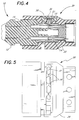
- Conductive pins 22 are positioned centrally in each aperture 28 so that the pins 22 fit into the conductor sockets 14 when the lead connector plug 12 is inserted into the yoke socket 20 (see Figure 4 for a cross-sectional view).
- a beaded retaining rod 32 comprises a rod with a number of expanded "bead-like" sections 32a connected by straight sections 32b.
- the retaining rod 32 is inserted into the yoke socket body 24 so that the bead-like sections 32a are positioned to interact with the retention recesses 19 of inserted lead connector plugs 12.
- a top view, Figure 5, of the yoke plug 20 shows that a series of openings 34 are provided, one for each square coaxial aperture 28b.
- the bead-like sections 32a extend into the openings 34 and interact with the rounded retention recesses 19 of any inserted lead connector plug 12.
- the rod sections 32b are stopped by socket material between the openings 34 so that the retaining rod 32 does not protrude excessively into the square apertures 28b.
- a layer of a resilient material 36 such as rubber is placed on top of the retaining rod 32 and a retaining rod keeper 38 is placed above and captures the resilient material 36.
- the keeper 38 is sized to compress the resilient material 36 which, in turn, presses on the retaining rod 32 biasing it into contact with any coaxial insulator 18b that is inserted into one of the coaxial apertures 28b.
- a leading edge of the coaxial insulator 18b presses the bead-like section 32a of the retaining rod 32 up into the resilient material 36 until the retaining recess 19 aligns with the retaining rod 32.
- Figure 10 is a cross-sectional view illustrating the interaction between the resilient material 36, the keeper 38 and the beaded rod 32.
- the rod sections 32b between the bead-like sections 32a are somewhat flexible, allowing individual bead-like section 32a a small amount of movement independent of the entire retaining rod 32. This affords some mechanical isolation between the detents of adjacent lead connector plugs 12 inserted into the same yoke socket 20.
- the degree of mechanical isolation of the individual plugs 12 depends on the resilient character of the material used to form the retaining rod 32. If the rod 32 is made from a more flexible, resilient plastic material, the degree of mechanical isolation is increased. It is also possible to mold or string the individual bead-like sections 32a onto a thin flexible fiber such as a nylon monofilament much like the construction of a strand of beaded curtain. In this case the bead-like sections 32a can be a very hard material with the flexible nylon interconnections allowing maximal mechanical isolation between the individual plugs 12.
- the resilient material 36 can be natural rubber with a hardness of approximately 30 Shore A. Other elastomers of a similar springiness can be readily substituted for the rubber. Many suitable elastomers will occur to one of ordinary skill in the art such as urethane, neoprene, vinyl polymer, and silicone rubber.
- the resilient material 36 can be a corrugated metal leaf spring 36', preferably with the corrugations spaced to optimally interact with the bead-like sections 32a. The interaction between the thickness of the resilient material 36, its hardness/elasticity characteristics, and the degree of compression caused by the keeper 38 all control the amount of force required to pull the retained lead connector plug 12 from the yoke socket 20.
- individual ball bearings backed by individual springs or by resilient material 36 would accomplish a similar function, individual ball bearings are much more difficult to contain than the retaining rod 32, especially during assembly.
- a uniform, rather than a beaded, rod may also be used; however, such a design does not afford mechanical isolation as does the preferred beaded rod 32.
- a presently preferred way of utilizing the present invention is to attach the yoke socket body 24 to a small circuit board 17 to which a cable 30 is also attached.
- the circuit board 17 is sized to slide into slots (not shown) on an end of the yoke socket body 24 opposite the apertures 28.
- the circuit board 17 bears conducting pins 22 which are inserted into the yoke socket body 24 during the assembly procedure.
- the circuit board may also contain resistors and other electronic components that may be required for safety or noise suppression, etc.
- the yoke socket body 24 including circuit board 17 assembly is injection molded with polyethylene 39 to completely encase the circuit board 17 and seal it onto the yoke socket body 24 (see Figure 9).
- This completed assembly is wrapped with metal foil 31 to provide electrical shielding.
- the entire assembly is insert molded with a low durometer flexible rubber material 33 to provide an outer skin and strain relief 35 as shown in Figures 6a, 7b and 9.
- the final unit is totally sealed and protected by polyethylene 39 encasing the circuit board 17 and by the flexible rubber material 33 overcoating the polyethylene 39 and part of the cable 30.
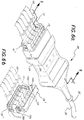
- the lead plug 12 bears recesses 15 that can be used with a lead wire combiner 16 to temporarily join a set of lead plugs 12 together.
- the lead combiner consists of two identical subunits 16' as shown in cross-section in Figure 7c. Each subunit 16' has a barb 16a at one end and a catch 16b at a second end.
- the interconnection system is "hermaphroditic" in that the barb 16a of one subunit 16' mates with the catch 16b of another subunit 16.' Any two subunits 16' can latch together to for a complete combiner 16.
- the combiner 16 is most easily used after the lead plugs 12 are aligned by being inserted into the yoke socket 20 as in Figure 6.
- the two pieces of the combiner 16 are then snapped together over the plugs 12. With the combiner 16 in place the aggregated plugs may be removed from and reinserted into the yoke socket 20 as a combined unit. It is simple to bend one of the barbs 16a away from its mating catch 16b and separate the two subunits 16' to release the aggregated lead plugs 12.
Landscapes
- Health & Medical Sciences (AREA)
- Life Sciences & Earth Sciences (AREA)
- Engineering & Computer Science (AREA)
- Heart & Thoracic Surgery (AREA)
- Molecular Biology (AREA)
- Biophysics (AREA)
- Pathology (AREA)
- Biomedical Technology (AREA)
- Microelectronics & Electronic Packaging (AREA)
- Medical Informatics (AREA)
- Physics & Mathematics (AREA)
- Surgery (AREA)
- Animal Behavior & Ethology (AREA)
- General Health & Medical Sciences (AREA)
- Public Health (AREA)
- Veterinary Medicine (AREA)
- Connector Housings Or Holding Contact Members (AREA)
- Details Of Connecting Devices For Male And Female Coupling (AREA)
- Measurement And Recording Of Electrical Phenomena And Electrical Characteristics Of The Living Body (AREA)
Abstract
Description
- There is a considerable need for reliable electrical plug connectors particularly in the field of medical testing equipment such as electrocardiogram (ECG) cables and leads. In such tests shielded leads are attached at one end to conductive pads attached at various points on the human body and at another end to lead connector plugs. The plurality of shielded lead connector plugs are then inserted into a common cable yoke socket on a common cable connected to a monitoring instrument. It is important that the various lead connector plugs be readily and securely attached to the yoke plug so that patient movement will not cause an inadvertent disconnection.
- As might be imagined, there has been a considerable effort in the industry to produce standardized lead plug and yoke socket design, both to ensure adequate performance of various leads and cable yokes and to allow interchangeability between leads and yokes produced by different manufacturers. To this end an industry/clinician working group, the Association for the Advancement of Medical Instrumentation (AAMI), together with the American Nation Standards Institute (ANSI), has promulgated ANSI/AAMI EC53-1995, a standard for ECG leads, plugs, and yoke sockets. This standard defines the configurations of lead connector plugs and yoke sockets intended to accept those lead connector plugs. The standard allows the manufacturers a certain amount of design leeway as long as the leads and yokes otherwise meet the standard and remain interchangeable. Specifically, while the yoke/lead plug design specified in EC53 does not provide retention means to ensure against inadvertent removal of a lead connector plug from a yoke socket, the standard specifically encourages manufacturers to make modifications designed to provide retention forces to the cable yoke socket/lead plug combination.
- The prior art has provided several different designs intended to ensure retention of lead plugs in yoke sockets similar to those used in ECG. For example, United States Patent No. 4,913,667 to Muz describes a lead plug and yoke socket system including a casing intended to reversibly link together a group of lead plugs, as well as a yoke socket equipped with retention force enhancers intended to retain the lead plugs in the yoke socket against accidental disconnection.
- In the Muz patent each lead plug is equipped with two separate connectors, one for a signal lead and one for a coaxial shield surrounding the signal lead. These separate connectors are shape-keyed (one round and one square) to ensure correct polarity and are joined by a single basal plug body. The square connector of each pair exhibits a recess or notch intended to interact with force retention enhancers when the connector is inserted into the cable yoke socket. These retention enhancers are provided by a blade stop spring having a free end segment received by the recess.
- A potential problem with the blade stop spring is that should the spring become bent or fatigued, it will no longer provide adequate lead plug retention. Furthermore, a common free end segment is provided to interact with the several lead plugs that may be inserted into one cable yoke socket. This arrangement may provide an undesirable degree of mechanical interconnection between the individual lead plugs.
- An additional feature in the above-cited Muz patent is a plug combiner which serves to aggregate a set of lead plugs into one convenient unit. Unfortunately, the plug combiner of this invention is a closed unit so that individual plugs are best slipped into the combiner prior to insertion in the yoke socket. However, this can be a clumsy operation since a plurality of plugs and leads must be held in the proper configuration until a lock strip on the combiner is closed.
- In accordance with a first aspect of the present invention there is provided a yoke socket for removably retaining lead plugs when lead plugs are inserted into the yoke socket, the yoke socket comprising:
- a yoke socket body having, on a first surface thereof, a row of apertures, each aperture sized to accept a connector of an individual lead plug, when a connector is inserted into one of the apertures and each aperture forming a mouth of a bore penetrating the socket body and sized to accept the connector;
- a row of openings on a second surface of the yoke socket body, each opening penetrating the yoke socket body and intersecting one of the bores, each opening disposed to expose a connector surface when a connector is inserted into the bore which the opening intersects;
- a beaded rod of alternating straight and bead-like regions, the bead-like regions spaced apart by the straight regions and sized so that the rod can be placed in contact with the yoke socket body with one of the bead-like regions intruding into each opening to lie within a retaining recess on a connector surface when a lead plug is inserted into one of the bores;
- a piece of resilient material sized to cover the beaded rod; and
- a keeper sized to cover and compress the resilient material, biasing the bead-like sections to provide detents for retaining lead plugs when lead plugs are inserted into the yoke socket.
- In accordance with a second aspect of the present invention there is provided a socket for removably retaining plugs, the socket comprising:
- a socket body having, on a first surface, apertures forming mouths to bores sized to accept connectors born by the plugs;
- a groove cut into a second surface of the socket body to expose a portion of a connector when one of the connectors is inserted into one of the bores;
- a rod disposed within the groove and sized to interact with a retaining recess on an exposed portion of one of the connectors when one of the connectors is inserted into one of the bores;
- a piece of resilient material sized to cover a portion of the rod; and
- means for compressing the resilient material, biasing the rod to provide a detent for retaining a plug in the socket when a plug is inserted therein.
- In accordance with a third aspect of the present invention there is provided a yoke socket system for removably retaining individual lead plugs, the yoke socket system comprising:
- a lead plug having at one end a connector with a retention recess on a lateral surface thereof; and
- a yoke socket comprising:
- a socket body having an aperture forming a mouth of a bore sized to accept the connector; and
- a locking mechanism comprising:
- a locking rod sized to fit the retention recess;
- a groove in the yoke socket, the groove penetrating into the bore and with the locking rod disposed in the groove to reach the retention recess;
- resilient material sized to cover the locking rod; and
- means for compressing the resilient material to bias the locking rod towards the retaining recesses providing a detent for stabilizing an interaction between the yoke socket and the lead plug when the plug is inserted into the yoke socket.
- In accordance with a fourth aspect of the present invention there is provided a yoke socket system for removably retaining lead plugs, the yoke socket system comprising:
- lead plugs comprising:
- leads;
- lead plug bodies with connection recesses, one of the leads attached to a first end of each of the lead plug bodies; and
- connectors with retention recesses on a lateral surface thereof, one of the connectors attached to a second end of each of the lead plug bodies;
- a yoke socket comprising:
- a socket body having an aperture forming a mouth to a bore sized to accept one of the connectors; and
- a locking mechanism comprising:
- a locking rod sized to fit the retention recess;
- a groove in the yoke socket penetrating into the bore with the locking rod disposed in the groove to reach the retention recess;
- resilient material sized to cover the locking rod; and
- means for compressing the resilient material to bias the locking rod towards the retaining recesses providing a detent for stabilizing an interaction between the yoke socket and the lead plug when the plug is inserted into the yoke socket; and
- a plug combiner comprising two interconnectable combiner sections for connecting together around the lead plugs and temporarily aggregating them into an assembly by interacting with the connection recesses.
- The present invention produces a simple socket design for use with ECG lead plugs and similar connectors.
- The present invention also provides an improved force retention locking mechanism for the socket without requiring blade spring stops of the prior art.
- The present invention also provides a socket locking mechanism that allows semi-mechanical isolation between the separate lead plugs which are inserted into the socket.
- The present invention also provides a simple to use plug combiner that can be applied after the individual plugs are inserted into the socket.
- The present invention provides an improved socket for use with separate leads and plugs, such as those used with electrocardiogram devices, which provides detents to guard against accidental disconnection of plugs from the socket. In a preferred embodiment the yoke socket bears a row of apertures into which can be inserted connectors born by the individual lead plugs. In addition, openings at approximately right angles to the apertures expose portions of connectors inserted into the socket. The exposed portion of each connector has a notch that acts in concert with a retaining rod within the yoke socket to retain the plug against accidental detaching. The retaining rod comprises a series of expanded or bead-like portions connected by thinner rod portions. The expanded portion is sized to protrude into an aperture through one of the openings interacting with the notch of an inserted connector and serving as a detent. The entire retaining rod is backed by a layer of compressed elastomer such as a rubber which acts to bias the retaining rod into contact with the connector. Once the plugs are held by the yoke socket, a two piece plug combiner can be snapped in place onto the plugs to removably aggregate them into a single unit.
- The present invention, both as to its organization and manner of operation, together with further objects and advantages, may best be understood by reference to the following description, taken in connection with the accompanying drawings.
- Figure 1 shows an example of a lead and a lead plug used in the present invention;
- Figure 2 illustrates an exploded view of an example of a yoke socket of the present invention;
- Figure 3 shows an example of the yoke socket of the present invention with one of the lead plugs inserted therein;
- Figure 4 shows a cross-sectional view of the lead plug inserted into the yoke socket;
- Figure 5 shows a top view of an example of the yoke socket of the present invention;
- Figure 6a shows an example of a finished socket and plugs of the present invention along with one half of a plug combiner;
- Figure 6b shows how the plug combiner is used to aggregate several lead plugs;
- Figure 7a shows a group of plugs aggregated by the plug combiner;
- Figure 7b shows a rear portion of a completed yoke socket;
- Figure 7c shows a cross-section of the plug combiner of Figure 7a;
- Figure 8a shows the first step in constructing an example of a lead plug of the present invention;
- Figure 8b shows the second step in constructing the lead plug;
- Figure 8c shows the third step in constructing the lead plug;
- Figure 9 shows a cross-section of part of an example of a lead plug and completed yoke socket of the present invention;
- Figure 10 shows a cross-section of the yoke socket illustrating a relationship between the beaded rod and the connectors of the lead plug; and
- Figure 11 shows a cross-section of an alternative embodiment wherein a corrugated leaf spring serves as the resilient material.
- Figure 1 shows an
ECG lead 10 andlead connector plug 12 which are compliant with Standard EC53 and can be used with ayoke socket 20 of the present invention. Thelead 10 joins alead plug base 13 surrounded aflexible rubber skin 9 that tapers into astrain relief 11. As shown in Figure 8 this structure is preferably produced by attaching electrical conductors of thelead 10 to individual conductor sockets 14 (Figure 8a) and then using an injection molding technique to form thelead plug base 13 andinsulators 18 around thelead 10 and the individual conductor sockets 14 (Figure 8b). Note that theinsulators 14 are continuous with thelead plug base 13. This plug base-insulator assembly is then injection molded with a flexible rubber compound to form therubber skin 9 and the strain relief 11 (Figure 8c). - Each
lead connector plug 12 comprises twoconductive sockets 14 sized to acceptconductive pins 22 and the associatedinsulators 18 which surrounds eachsocket 14 so that thesockets 14 cannot be accidentally shorted together. Theinsulators 18 of the twosockets 14 of eachlead connector plug 12 are of different shapes so that signal polarity can be automatically maintained. Theinsulator 18a of the signal lead is round in cross-section, while theinsulator 18b of the coaxial shield is square. A surface of thesquare insulator 18b opposite theround insulator 18a bears a rounded retention recess or notch 19 to help retain theconnector plug 12 when it is inserted into theyoke socket 20. - Figure 2 shows an exploded view of the
yoke socket 20. Theyoke socket 20 can be produced as a two part "clam shell" configuration or, preferably, as a single injection molded part as illustrated. Ayoke socket body 24 has ayoke socket 25 sized to accept a plurality of lead connector plugs 12. In this case theyoke socket 25 can accommodate five lead connector plugs 12, but theyoke sockets 20 can be readily manufactured to accommodate a larger or smaller number of lead connector plugs 12. Theyoke socket 25 is defined by acollar 26 surrounding afront face 27 of theyoke socket body 24. - As shown in Figure 3, the
collar 26 partially encloses thelead connector base 13 when thelead connector plug 12 is inserted into theyoke plug 20. Thefront face 27 bears pairs ofapertures 28. Theapertures 28 are the mouths of bores extending into theyoke socket body 24 and sized to fit theinsulators 18 of the lead connector plugs 12. Theround signal insulator 18a fits into a round aperture 28a while the squarecoaxial aperture 18b fits into a squarecoaxial aperture 28b.Conductive pins 22 are positioned centrally in eachaperture 28 so that thepins 22 fit into theconductor sockets 14 when thelead connector plug 12 is inserted into the yoke socket 20 (see Figure 4 for a cross-sectional view). - A
beaded retaining rod 32 comprises a rod with a number of expanded "bead-like"sections 32a connected bystraight sections 32b. The retainingrod 32 is inserted into theyoke socket body 24 so that the bead-like sections 32a are positioned to interact with the retention recesses 19 of inserted lead connector plugs 12. A top view, Figure 5, of theyoke plug 20 shows that a series ofopenings 34 are provided, one for each squarecoaxial aperture 28b. When the retaining rod is inserted into theyoke socket body 24, the bead-like sections 32a extend into theopenings 34 and interact with the rounded retention recesses 19 of any insertedlead connector plug 12. Therod sections 32b are stopped by socket material between theopenings 34 so that the retainingrod 32 does not protrude excessively into thesquare apertures 28b. - A layer of a
resilient material 36 such as rubber is placed on top of the retainingrod 32 and a retainingrod keeper 38 is placed above and captures theresilient material 36. Thekeeper 38 is sized to compress theresilient material 36 which, in turn, presses on the retainingrod 32 biasing it into contact with anycoaxial insulator 18b that is inserted into one of thecoaxial apertures 28b. As thelead connector 12 is inserted into theyoke socket 20, a leading edge of thecoaxial insulator 18b presses the bead-like section 32a of the retainingrod 32 up into theresilient material 36 until the retainingrecess 19 aligns with the retainingrod 32. At that point the bead-like section 32a is forced into the retainingrecess 19 where it acts as a detent to retain thelead plug 12 in theyoke socket 20 against accidental removal. Figure 10 is a cross-sectional view illustrating the interaction between theresilient material 36, thekeeper 38 and thebeaded rod 32. - The
rod sections 32b between the bead-like sections 32a are somewhat flexible, allowing individual bead-like section 32a a small amount of movement independent of the entire retainingrod 32. This affords some mechanical isolation between the detents of adjacent lead connector plugs 12 inserted into thesame yoke socket 20. The degree of mechanical isolation of the individual plugs 12 depends on the resilient character of the material used to form the retainingrod 32. If therod 32 is made from a more flexible, resilient plastic material, the degree of mechanical isolation is increased. It is also possible to mold or string the individual bead-like sections 32a onto a thin flexible fiber such as a nylon monofilament much like the construction of a strand of beaded curtain. In this case the bead-like sections 32a can be a very hard material with the flexible nylon interconnections allowing maximal mechanical isolation between the individual plugs 12. - The
resilient material 36 can be natural rubber with a hardness of approximately 30 Shore A. Other elastomers of a similar springiness can be readily substituted for the rubber. Many suitable elastomers will occur to one of ordinary skill in the art such as urethane, neoprene, vinyl polymer, and silicone rubber. Alternatively, as shown in Figure 11, theresilient material 36 can be a corrugated metal leaf spring 36', preferably with the corrugations spaced to optimally interact with the bead-like sections 32a. The interaction between the thickness of theresilient material 36, its hardness/elasticity characteristics, and the degree of compression caused by thekeeper 38 all control the amount of force required to pull the retained lead connector plug 12 from theyoke socket 20. Although individual ball bearings backed by individual springs or byresilient material 36 would accomplish a similar function, individual ball bearings are much more difficult to contain than the retainingrod 32, especially during assembly. A uniform, rather than a beaded, rod may also be used; however, such a design does not afford mechanical isolation as does the preferred beadedrod 32. - After the locking mechanism which comprises the retaining
rod 32, theresilient material 36 and therod keeper 38 are assembled, a presently preferred way of utilizing the present invention is to attach theyoke socket body 24 to asmall circuit board 17 to which acable 30 is also attached. Thecircuit board 17 is sized to slide into slots (not shown) on an end of theyoke socket body 24 opposite theapertures 28. Thecircuit board 17bears conducting pins 22 which are inserted into theyoke socket body 24 during the assembly procedure. The circuit board may also contain resistors and other electronic components that may be required for safety or noise suppression, etc. - After the
circuit board 17 is added, theyoke socket body 24 includingcircuit board 17 assembly is injection molded withpolyethylene 39 to completely encase thecircuit board 17 and seal it onto the yoke socket body 24 (see Figure 9). This completed assembly is wrapped withmetal foil 31 to provide electrical shielding. Finally the entire assembly is insert molded with a low durometerflexible rubber material 33 to provide an outer skin andstrain relief 35 as shown in Figures 6a, 7b and 9. The final unit is totally sealed and protected bypolyethylene 39 encasing thecircuit board 17 and by theflexible rubber material 33 overcoating thepolyethylene 39 and part of thecable 30. - The lead plug 12 bears recesses 15 that can be used with a
lead wire combiner 16 to temporarily join a set of lead plugs 12 together. The lead combiner consists of two identical subunits 16' as shown in cross-section in Figure 7c. Each subunit 16' has abarb 16a at one end and acatch 16b at a second end. The interconnection system is "hermaphroditic" in that thebarb 16a of one subunit 16' mates with thecatch 16b of anothersubunit 16.' Any two subunits 16' can latch together to for acomplete combiner 16. Thecombiner 16 is most easily used after the lead plugs 12 are aligned by being inserted into theyoke socket 20 as in Figure 6. The two pieces of thecombiner 16 are then snapped together over theplugs 12. With thecombiner 16 in place the aggregated plugs may be removed from and reinserted into theyoke socket 20 as a combined unit. It is simple to bend one of thebarbs 16a away from itsmating catch 16b and separate the two subunits 16' to release the aggregated lead plugs 12.
Claims (12)
- A yoke socket for removably retaining lead plugs when lead plugs are inserted into the yoke socket, the yoke socket comprising:a yoke socket body having, on a first surface thereof, a row of apertures, each aperture sized to accept a connector of an individual lead plug, when a connector is inserted into one of the apertures and each aperture forming a mouth of a bore penetrating the socket body and sized to accept the connector;a row of openings on a second surface of the yoke socket body, each opening penetrating the yoke socket body and intersecting one of the bores, each opening disposed to expose a connector surface when a connector is inserted into the bore which the opening intersects;a beaded rod of alternating straight and bead-like regions, the bead-like regions spaced apart by the straight regions and sized so that the rod can be placed in contact with the yoke socket body with one of the bead-like regions intruding into each opening to lie within a retaining recess on a connector surface when a lead plug is inserted into one of the bores;a piece of resilient material sized to cover the beaded rod; anda keeper sized to cover and compress the resilient material, biasing the bead-like sections to provide detents for retaining lead plugs when lead plugs are inserted into the yoke socket.
- A socket for removably retaining plugs, the socket comprising:a socket body having, on a first surface, apertures forming mouths to bores sized to accept connectors born by the plugs;a groove cut into a second surface of the socket body to expose a portion of a connector when one of the connectors is inserted into one of the bores;a rod disposed within the groove and sized to interact with a retaining recess on an exposed portion of one of the connectors when one of the connectors is inserted into one of the bores;a piece of resilient material sized to cover a portion of the rod;
andmeans for compressing the resilient material, biasing the rod to provide a detent for retaining a plug in the socket when a plug is inserted therein. - The socket of claim 2, wherein the rod comprises alternating sections, expanded bead-like sections interconnected by thinner sections and wherein the bead-like sections interact with retaining recesses.
- The socket of claim 3, wherein the thinner rod sections comprise portions of a continuous flexible filament with the bead-like sections attached to the filament and spaced apart thereon.
- A yoke socket system for removably retaining individual lead plugs, the yoke socket system comprising:a lead plug having at one end a connector with a retention recess on a lateral surface thereof; anda yoke socket comprising:a socket body having an aperture forming a mouth of a bore sized to accept the connector; anda locking mechanism comprising:a locking rod sized to fit the retention recess;a groove in the yoke socket, the groove penetrating into the bore and with the locking rod disposed in the groove to reach the retention recess;resilient material sized to cover the locking rod; andmeans for compressing the resilient material to bias the locking rod towards the retaining recesses providing a detent for stabilizing an interaction between the yoke socket and the lead plug when the plug is inserted into the yoke socket.
- The socket system of claim 5, wherein the rod comprises alternating sections, expanded bead-like sections interconnected by thinner more flexible sections and wherein the bead-like sections interact with the retaining recesses.
- The socket system of claim 6, wherein the thinner rod sections comprise portions of a continuous flexible filament with the bead-like sections spaced apart thereon.
- The socket system of any of claims 5 to 7 further comprising connection recesses on the lead plugs and a plug combiner including two interconnectable combiner sections for connecting together around the lead plugs and temporarily aggregating the lead plugs into an assembly by interacting with lead plug connection recesses.
- A yoke socket system for removably retaining lead plugs, the yoke socket system comprising:lead plugs comprising:leads;lead plug bodies with connection recesses, one of the leads attached to a first end of each of the lead plug bodies;
andconnectors with retention recesses on a lateral surface thereof, one of the connectors attached to a second end of each of the lead plug bodies;a yoke socket comprising:a socket body having an aperture forming a mouth to a bore sized to accept one of the connectors; anda locking mechanism comprising:a locking rod sized to fit the retention recess;a groove in the yoke socket penetrating into the bore with the locking rod disposed in the groove to reach the retention recess;resilient material sized to cover the locking rod; andmeans for compressing the resilient material to bias the locking rod towards the retaining recesses providing a detent for stabilizing an interaction between the yoke socket and the lead plug when the plug is inserted into the yoke socket; anda plug combiner comprising two interconnectable combiner sections for connecting together around the lead plugs and temporarily aggregating them into an assembly by interacting with the connection recesses. - The yoke socket system of claim 8 or 9, wherein the two combiner sections are identical.
- The socket or socket system of any of the preceding claims, wherein the resilient material is an elastomer selected from the group consisting of natural rubber, urethane, neoprene, vinyl polymer, and silicone rubber.
- The socket or socket system of any of the preceding claims, wherein the resilient material is provided by a corrugated leaf spring.
Applications Claiming Priority (2)
| Application Number | Priority Date | Filing Date | Title |
|---|---|---|---|
| US596647 | 1996-02-05 | ||
| US08/596,647 US5632643A (en) | 1996-02-05 | 1996-02-05 | Electronic cable yoke socket with locking mechanism |
Publications (2)
| Publication Number | Publication Date |
|---|---|
| EP0788196A2 true EP0788196A2 (en) | 1997-08-06 |
| EP0788196A3 EP0788196A3 (en) | 1998-05-13 |
Family
ID=24388123
Family Applications (1)
| Application Number | Title | Priority Date | Filing Date |
|---|---|---|---|
| EP96309572A Ceased EP0788196A3 (en) | 1996-02-05 | 1996-12-31 | Plug socket |
Country Status (3)
| Country | Link |
|---|---|
| US (1) | US5632643A (en) |
| EP (1) | EP0788196A3 (en) |
| NO (1) | NO970496L (en) |
Families Citing this family (19)
| Publication number | Priority date | Publication date | Assignee | Title |
|---|---|---|---|---|
| US6059615A (en) * | 1997-01-31 | 2000-05-09 | Berg Technology, Inc. | Modular cable to board power connector |
| DE10127504B4 (en) * | 2001-06-06 | 2013-08-22 | Volkswagen Ag | Receiving device for an electrical component with at least one connector receptacle |
| US6761469B2 (en) * | 2002-10-23 | 2004-07-13 | Wen-Chang Wu | Electrical connecting structure for a lamp |
| US6793537B2 (en) * | 2002-12-30 | 2004-09-21 | Methode Electronics, Inc. | Wire connector assembly and method of forming same |
| US6881101B2 (en) * | 2003-02-20 | 2005-04-19 | Rockwell Automation Technologies, Inc. | Modular electrical device |
| DE10326402A1 (en) * | 2003-06-12 | 2004-12-30 | Antea Medizintechnik + Informationstechnik Gmbh | Electrode sensor system, in particular for recording an electrocardiogram |
| DE10334071B4 (en) * | 2003-07-25 | 2005-07-07 | Siemens Ag | Plug connection system with integrated lock |
| US8668651B2 (en) | 2006-12-05 | 2014-03-11 | Covidien Lp | ECG lead set and ECG adapter system |
| NO333565B1 (en) * | 2008-10-22 | 2013-07-08 | Med Storm Innovation As | Electrical assembly for medical purpose |
| DE102009048877A1 (en) * | 2009-10-09 | 2011-04-14 | Harting Electric Gmbh & Co. Kg | Cable entry in connector housings |
| US8668504B2 (en) | 2011-07-05 | 2014-03-11 | Dave Smith Chevrolet Oldsmobile Pontiac Cadillac, Inc. | Threadless light bulb socket |
| US8634901B2 (en) | 2011-09-30 | 2014-01-21 | Covidien Lp | ECG leadwire system with noise suppression and related methods |
| US8834195B2 (en) * | 2012-12-04 | 2014-09-16 | Amphenol Corporation | Cable connector system |
| EP2742968A1 (en) * | 2012-12-13 | 2014-06-18 | Sapiens Steering Brain Stimulation B.V. | A probe, especially a probe for neural applications |
| ES2969182T3 (en) | 2014-04-25 | 2024-05-16 | Kpr Us Llc | Physical shield for ECG electrical connections |
| US9478929B2 (en) | 2014-06-23 | 2016-10-25 | Ken Smith | Light bulb receptacles and light bulb sockets |
| JP6776037B2 (en) * | 2016-07-20 | 2020-10-28 | 日本航空電子工業株式会社 | Connector assembly |
| WO2019043023A1 (en) * | 2017-08-31 | 2019-03-07 | Koninklijke Philips N.V. | Sensing guidewire with integrated proximal locking feature |
| CN114246590A (en) * | 2020-09-10 | 2022-03-29 | 疆域康健创新医疗科技成都有限公司 | Electrode plate and connecting wire connected with same |
Citations (1)
| Publication number | Priority date | Publication date | Assignee | Title |
|---|---|---|---|---|
| US4913667A (en) | 1988-03-09 | 1990-04-03 | Nicolay Gmbh | Connector system with replaceable plugs |
Family Cites Families (4)
| Publication number | Priority date | Publication date | Assignee | Title |
|---|---|---|---|---|
| US2428214A (en) * | 1945-10-18 | 1947-09-30 | Grafiex Inc | Electrical connecting plug and receiving member or receptacle therefor |
| US4227762A (en) * | 1979-07-30 | 1980-10-14 | Vaughn Corporation | Electrical connector assembly with latching bar |
| US4445742A (en) * | 1982-02-08 | 1984-05-01 | The Yellow Springs Instrument Company, Inc. | Electrical cable connector |
| US4610496A (en) * | 1985-05-24 | 1986-09-09 | Flight Connector Corporation | Connector mechanical interlock using ball detents |
-
1996
- 1996-02-05 US US08/596,647 patent/US5632643A/en not_active Expired - Lifetime
- 1996-12-31 EP EP96309572A patent/EP0788196A3/en not_active Ceased
-
1997
- 1997-02-04 NO NO970496A patent/NO970496L/en unknown
Patent Citations (1)
| Publication number | Priority date | Publication date | Assignee | Title |
|---|---|---|---|---|
| US4913667A (en) | 1988-03-09 | 1990-04-03 | Nicolay Gmbh | Connector system with replaceable plugs |
Also Published As
| Publication number | Publication date |
|---|---|
| US5632643A (en) | 1997-05-27 |
| NO970496D0 (en) | 1997-02-04 |
| NO970496L (en) | 1997-08-06 |
| EP0788196A3 (en) | 1998-05-13 |
Similar Documents
| Publication | Publication Date | Title |
|---|---|---|
| US5632643A (en) | Electronic cable yoke socket with locking mechanism | |
| US5803770A (en) | Connector for electrical cable and method of making | |
| US20220224057A1 (en) | Controlled-impedance compliant cable termination | |
| US7192301B2 (en) | Electrical connector | |
| JP2938450B2 (en) | Shield connector with latch | |
| KR101083543B1 (en) | Miniature Circular Connector System | |
| US20150163601A1 (en) | System for hearing assistance device including receiver in the canal | |
| EP0520603B1 (en) | A rotary electrical connector with remote modular connector | |
| EP1147783A2 (en) | Electrical connector for multi-contact medical electrodes | |
| EP2755283B1 (en) | User Configurable Connector | |
| EP2304853B1 (en) | High density rectangular interconnect | |
| US5941722A (en) | Crimp connector | |
| EP2811582A1 (en) | Electric connector | |
| CA2249723C (en) | Multi-contact electrical terminal for electrical receptacle assembly | |
| US5924891A (en) | Connector assembly for flat circuitry | |
| EP0952629A3 (en) | Electrical connector for flat flexible circuitry | |
| US5338230A (en) | Electrical connector assembly | |
| US6283793B1 (en) | Electrical connector system | |
| US5743754A (en) | Electrical multi-pin snap connector | |
| US5816841A (en) | Electrical disconnect for telephone headset | |
| KR960012624A (en) | Electrical cable assembly | |
| EP0442215A1 (en) | Modular connector assembly which provides strain relief | |
| EP1380073B1 (en) | Electrical connector for connecting flat flexible cricuitry to discrete terminal pins | |
| US20020086583A1 (en) | Electrical connector having combined cable attachment and shielding | |
| EP0578487A1 (en) | Electrical pin field |
Legal Events
| Date | Code | Title | Description |
|---|---|---|---|
| PUAI | Public reference made under article 153(3) epc to a published international application that has entered the european phase |
Free format text: ORIGINAL CODE: 0009012 |
|
| AK | Designated contracting states |
Kind code of ref document: A2 Designated state(s): BE CH DE DK ES FI FR GB IT LI NL SE |
|
| PUAL | Search report despatched |
Free format text: ORIGINAL CODE: 0009013 |
|
| AK | Designated contracting states |
Kind code of ref document: A3 Designated state(s): BE CH DE DK ES FI FR GB IT LI NL SE |
|
| 17P | Request for examination filed |
Effective date: 19981104 |
|
| 17Q | First examination report despatched |
Effective date: 19990921 |
|
| GRAG | Despatch of communication of intention to grant |
Free format text: ORIGINAL CODE: EPIDOS AGRA |
|
| STAA | Information on the status of an ep patent application or granted ep patent |
Free format text: STATUS: THE APPLICATION HAS BEEN REFUSED |
|
| 18R | Application refused |
Effective date: 20010930 |
|
| RIN1 | Information on inventor provided before grant (corrected) |
Inventor name: ROSSINI,HENRY G. Inventor name: OLMS,HARALD O. Inventor name: SHEPHERD,DAVID J. |