EP0785600B1 - Optical systems and devices employing spectrally flattened amplified spontaneous emission - Google Patents
Optical systems and devices employing spectrally flattened amplified spontaneous emission Download PDFInfo
- Publication number
- EP0785600B1 EP0785600B1 EP97300064A EP97300064A EP0785600B1 EP 0785600 B1 EP0785600 B1 EP 0785600B1 EP 97300064 A EP97300064 A EP 97300064A EP 97300064 A EP97300064 A EP 97300064A EP 0785600 B1 EP0785600 B1 EP 0785600B1
- Authority
- EP
- European Patent Office
- Prior art keywords
- fiber
- rare earth
- earth doped
- light source
- long period
- Prior art date
- Legal status (The legal status is an assumption and is not a legal conclusion. Google has not performed a legal analysis and makes no representation as to the accuracy of the status listed.)
- Expired - Lifetime
Links
Images


Classifications
-
- H—ELECTRICITY
- H01—ELECTRIC ELEMENTS
- H01S—DEVICES USING THE PROCESS OF LIGHT AMPLIFICATION BY STIMULATED EMISSION OF RADIATION [LASER] TO AMPLIFY OR GENERATE LIGHT; DEVICES USING STIMULATED EMISSION OF ELECTROMAGNETIC RADIATION IN WAVE RANGES OTHER THAN OPTICAL
- H01S3/00—Lasers, i.e. devices using stimulated emission of electromagnetic radiation in the infrared, visible or ultraviolet wave range
- H01S3/05—Construction or shape of optical resonators; Accommodation of active medium therein; Shape of active medium
- H01S3/06—Construction or shape of active medium
- H01S3/063—Waveguide lasers, i.e. whereby the dimensions of the waveguide are of the order of the light wavelength
- H01S3/067—Fibre lasers
- H01S3/06795—Fibre lasers with superfluorescent emission, e.g. amplified spontaneous emission sources for fibre laser gyrometers
-
- H—ELECTRICITY
- H01—ELECTRIC ELEMENTS
- H01S—DEVICES USING THE PROCESS OF LIGHT AMPLIFICATION BY STIMULATED EMISSION OF RADIATION [LASER] TO AMPLIFY OR GENERATE LIGHT; DEVICES USING STIMULATED EMISSION OF ELECTROMAGNETIC RADIATION IN WAVE RANGES OTHER THAN OPTICAL
- H01S2301/00—Functional characteristics
- H01S2301/04—Gain spectral shaping, flattening
-
- H—ELECTRICITY
- H01—ELECTRIC ELEMENTS
- H01S—DEVICES USING THE PROCESS OF LIGHT AMPLIFICATION BY STIMULATED EMISSION OF RADIATION [LASER] TO AMPLIFY OR GENERATE LIGHT; DEVICES USING STIMULATED EMISSION OF ELECTROMAGNETIC RADIATION IN WAVE RANGES OTHER THAN OPTICAL
- H01S3/00—Lasers, i.e. devices using stimulated emission of electromagnetic radiation in the infrared, visible or ultraviolet wave range
- H01S3/05—Construction or shape of optical resonators; Accommodation of active medium therein; Shape of active medium
- H01S3/06—Construction or shape of active medium
- H01S3/063—Waveguide lasers, i.e. whereby the dimensions of the waveguide are of the order of the light wavelength
- H01S3/067—Fibre lasers
- H01S3/0675—Resonators including a grating structure, e.g. distributed Bragg reflectors [DBR] or distributed feedback [DFB] fibre lasers
Description
- This invention relates to broadband amplified spontaneous emission light sources.
- Optical fibers are key components in modern telecommunications. Optical fibers are thin stands of glass capable of transmitting an optical signal containing a large amount of information over long distances with very low loss. In essence, an optical fiber is a small diameter waveguide characterized by a core with a first index of refraction surrounded by a cladding having a second (lower) index of refraction. Typical optical fibers are made of high purity silica with minor concentrations of dopants to control the index of refraction.
- Broadband light sources for such fiber are useful in a variety of applications. For example contemplated wavelength division multiplexing systems would divide a single broadband light source into a plurality of narrow-band carrier channels, separately modulate the carrier channels and simultaneously transmit the separately modulated channels over a single fiber. Such broadband sources are also potentially useful in fiber sensing systems and in imaging applications.
- Unfortunately, conventional light sources fail to provide broad bandwidth light at uniform high levels of power. One conventional approach is to use fibers doped with rare earth elements such as Nd, Er, Yb as spontaneous emission sources. While these sources provide broadband light at low levels of power, their output spectra quickly narrow as the power increases. Moreover, at high pumping powers they tend to lase from small reflections, such as are presented by the fiber endfaces.
- Another approach to providing broad bandwidth light is the use of super luminescent diodes. Unfortunately, these devices often fail to provide adequate power, especially after losses incurred in coupling into fiber. Accordingly, there is a need for a new high power, broad bandwidth light source for optical fibers.
- DIGONNET M J F: 'Broadband rare-earth doped fiber laser sources' in 'OPTICAL FIBER ROTATION SENSING', BURNS W K edit., Academic Press 1994, Chapter 9, pages 303-336, discloses (see Section 3.1) single-pass and double-pass superfluorescent broadband amplified spontaneous emission fibre light sources, suitable for use in fibre-optic gyroscopes, comprising a length of rare earth doped optical fibre and a pump source coupled into the end of the fibre for exciting spontaneous optical emission in the fibre.
- US-A-5 430 817 (VENGSARKAR A M), 4 July 1995, discloses a long period grating coupled to an erbium doped fibre amplifier (see Fig.7 of this document) for flattening the spectral output of the amplified optical emission from the fibre, the long period grating comprising a length of fibre having a plurality of index perturbations of width w spaced apart by a periodic distance Λ where 50µm ≤ Λ ≤ 1500µm.
- According to this invention there is provided a light source as claimed in claim 1.
- A high power, broad bandwidth light source embodying the invention comprises at least one rare earth doped fiber coupled to a long period grating. When the rare earth doped fiber is pumped to operate as an amplified spontaneous emission source, the grating flattens and broadens the output spectrum. Using an Nd doped fiber, applicants have achieved an output power of 25 mW at a center wavelength of 1.08 µm, a spectral width of 40 nm and a coherence length of 10 µm. The source has a flat output spectrum with a maximum slope of 0.1 dB/nm across the full spectral width, and it can be conveniently dropped into any fiber system requiring high power and a broad spectrum.
- Using an Er-doped fiber, applicants have achieved an output power of 7.3 mW at a center wavelength of 1.55 µm and a spectral width of 38 nm. The source has a flat output spectrum with a maximum ripple of 1.7 dB across the full width. This source is compatible with the needs for a spectrum sliced source.
- In the drawings:
- FIG. 1 is a schematic view of a preferred broadband light source comprising dual stages of rare earth doped fiber.
- FIG. 2 is a graph useful in the design of a grating for removing light centered about a particular wavelength λp.
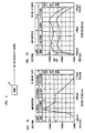
- FIGs. 3A and 3B are graphical illustrations of dual stage fiber sources before and after insertion of an intervening long period grating.
- FIG. 4 is a schematic view of an alternative broadband light source comprising a single stage of rare earth doped fiber; and
- FIGs. 5A and 5B are graphical illustrations of a single stage fiber source before and after insertion of a long period grating.
- FIG. 6 is a graphical illustration of dual stage fiber sources before and after insertion of an intervening long period grating.
-
- Referring to the drawings, FIG. 1 is a schematic view of a preferred broadband light source comprising a
pump source 10, first andsecond stages 11 and 12, respectively, of rare earth doped optical fiber, and an intervening long period grating 13 to flatten and broaden the spectral output. Thepump source 10 is typically a laser, such as a fiber laser, or a fiber pigtailed diode laser for exciting spontaneous optical emission in the rare earth doped fiber. The pump source should have a wavelength shorter than the desired center frequency of the broadband source and is maintained at power levels below those which cause lasing. Each rare earth dopedfiber stage 11, 12 comprises a length of glass fiber, such as silica glass fiber, doped with rare earth dopants such as Nd, Er, or Yb typically in therange 50 ppm (for Er) to 20,000 ppm (or 2 mole %) for high power sources that use Yb. The length of the fiber stage is typically in the range 0.1 to 100 m, depending upon the rare earth dopant level. - The long period grating 13 comprises a length of fiber having a plurality of index perturbations of width w spaced apart by a periodic distance Λ where, typically, 10µm≤Λ≤2000µm. Advantageously, 1/5Λ≤w≤4/5Λ and preferably w= 1/2Λ. The perturbations are preferably formed within the glass core of the fiber and preferably form an angle of (2°≤≤90°) with the longitudinal axis of the fiber. The fiber is designed to transmit broadband light of wavelength centered about a center wavelength λ. In general, long-period grating devices are those in which the period is at least 10 times larger than the wavelength of input light.
- The spacing Λ of the perturbations is chosen to shift transmitted light in the region of a selected wavelength λp from the guided mode into a non-guided mode, thereby reducing in intensity a band of light centered about λp. In contrast with conventional short period gratings which reflect light, these long period devices remove light without reflection by converting it from a guided mode to an un-guided (or nonguided) mode. A nonguided mode is a mode which is not propagated coherently in the core, and is typically a cladding mode, a radiation mode, or in the case of multilayer profiles, a ring mode.
- FIG. 2 is a graph illustrating the periodic spacing Λ for removing light centered about a wavelength λp. Thus, for example, to make a long period grating for removing light centered about 1540 nm, one chooses a spacing of about 760 µm.
- Preferably the spectral filter component is a long period grating formed in a single mode optical fiber having a silica core doped with photosensitive material such as germanium. Further, the fiber can be loaded with molecular hydrogen to enhance its photosensitivity. The long period grating 13 can then be formed by selectively exposing the core to beams intense light of width w at locations separated by Λ.
- The preferred exposure source is UV radiation from a KrF excimer laser. Proper spacing can be effected by exposing through a slit of width w and then moving the fiber to the next exposure site. Alternatively, the fiber can be exposed through an amplitude mask. Preferably the exposure dosage for each slit is on the order of 1000 pulses to 10,000 pulses of > 100 mJ/cm2 fluence/pulse, and the number of perturbations is in the range 10-300.
- In designing the long period grating to flatten and broaden the light source of FIG. 1, one first measures the spectral output of the stages without a long period grating to determine at least one output peak λp. The grating is then designed to remove light from λp.
- The extinction ratio of the grating is determined by the height of the peak at λp relative to the rest of the amplified spontaneous emission spectrum. The width and shape of the filtering properties of the grating are made to match the width and shape of the peak at λp.
- To make a source with a long period grating, any deviations from a flat output or desired source spectrum can be inverted and added to the long period grating design. A new long period grating can be made to match the new design. This process can be iterated until the desired source spectrum is achieved.
- In the embodiment of FIG. 1 the output is taken from the end of the second stage fiber. Alternatively, the output can be taken from the first stage using a directional coupler to exclude pump light.
- The long period grating 13 can be placed at any point along the rare earth doped
fiber 11 and 12. In other words, the rare earth doped fiber 11 can be any fraction of the sum length offiber 11 and 12. In the case where rare earth doped fiber 11 is removed, then the long period grating 13 adds no functionality to the source. In the case where rare earth dopedfiber 12 is removed, then the long period grating 13 does add functionality, it performs the filtering function as desired, but there typically is a significant power loss. In the case where rare earth dopedfibers 11 and 12 are of similar length, then the long period grating 13 acts as a filter as desired, but the amount of power lost is not as significant. For a source there is an optimal amount of rare earth doped fiber 11 before thefilter 13 andfiber 12 after thefilter 13. This optimal point lies where thefilter 13 continues to smooth or shape the output spectrum as desired, but there is a minimal amount of output power lost as compared to an unfiltered source. - The invention will become clearer by considering the following specific example. A rare-earth doped (Nd) fiber source without a grating comprises a 822 nm semiconductor pump diode coupled to a 3.8 m fiber. The device, without a long period grating, was excited to spontaneous emission by the pump, leading to an output power of 34 mw, spectral width of 7 nm and maximum slope of 2.2 dB/nm between 1060 nm and 1100 nm. The output spectrum, shown in FIG. 3A, shows a peak at 1.062 µm. The maximum slope was 2.2 dB/nm.
- To flatten its spectrum, a long period grating (written in a fiber with cutoff wavelength λc<950 nm) having spacing Λ=210µm w = 105µm, and length = 11 mm was designed to remove light from λp=1.062µm. When the long period grating was placed between the stages, the new spectral output is shown in FIG. 3B.
Curves 1 and 2 show the output from thesecond stage 12 for two different pump power levels. The output spectrum shape is stable with respect to the changes in the pump power level. The output power for the flattened spectra is 25 mW corresponding to a 1.3 dB loss compared to the unfiltered output. Both curves show a broader, flatter output having a lower maximum slope 0.1 dB/nm. - FIG. 4 schematically shows an alternative light source comprising a
pump 10, a single stage of rare earth doped fiber 11 and a long period grating 13. The single stage device has an output which is less flat and less efficient than the dual stage device but which is nonetheless a substantial improvement over conventional sources. - As a specific example, a rare earth doped fiber of Nd without a long period grating exhibited the output spectrum shown in FIG. 5A having a peak at 1.062 µm and a maximum slope of 2.2 dB/nm. With the addition of a long period grating to remove the peak at λp=1.062 µm, the device exhibited the output spectrum shown in FIG. 5B.
Curves 1 and 2 are at different input power levels. The maximum slope of 0.2 dB/nm is a 10:1 improvement over the conventional unfiltered device. - In tests the dual stage device performed well over a wide range of operating conditions with output powers from 20 mW down to 100 µ W. Over this range, the device maintained a large 40 nm spectral width. At a center wavelength of 1.08 µm, this width corresponds to a coherence length of 10 µm. The single stage device performs well but is not as robust in maintaining its shape over as wide an operating range.
- As a further specific example, a source utilizing a rare earth doped fiber of Er and constructed in a manner illustrated in FIG. 1 has an output spectrum illustrated in FIG. 6. Without the long period grating (13) present, the source had an output power of 8 mW and a spectrum as shown in curve 1. With the long period grating and the same pump power, the source had a power of 73 mW and spectrum as shown in
curve 2. As the pump (1) power was reduced the other lower power spectrum was produced, curves 3-5. For this case, two filters were added to reduce the peaks at λp1 = 1535 nm and λp2 = 1560 nm. In principle, any number of peaks can be filtered and the source can be further flattened or modified. - While FIG. 1 shows only two rare earth doped fiber sections, more than two such sections could be employed. And while only one long period grating is shown in FIGs. 1 and 4, more than one such grating can be employed. Furthermore, different rare earth doped fiber sections in the same device can be doped with different rare earths, and even a single rare earth doped fiber can be doped with more than one rare earth element.
Claims (8)
- A broadband amplified spontaneous emission light source for optical fiber comprising:a first length of rare earth doped optical fiber;a pump source coupled into said fiber for exciting spontaneous optical emission in said fiber; anda long period grating coupled to said rare earth doped fiber for flattening and broadening the spectral output of the optical amplified spontaneous emission from said fiber, said long period grating comprising a length of fiber having a plurality of index perturbations of width w spaced apart by a periodic distance Λ where 10µm≤Λ≤2000µm.
- A light source according to claim 1 further comprising a second length of rare earth doped optical fiber coupled to said first length of rare earth doped fiber.
- A light source according to claim 2 wherein broadband light output is taken from the end of said second length of rare earth doped fiber.
- A light source according to claim 2 wherein broadband light output is coupled from said first length of rare earth doped fiber.
- A light source according to claim 1 wherein said rare earth doped fiber is Nd doped fiber.
- A light source according to claim 1 wherein said rare earth doped fiber is Er doped fiber.
- A light source according to claim 1 wherein said rare earth doped fiber is doped with Er and Yb.
- A light source according to claim 1 wherein said rare earth doped fiber is doped with Nd and Yb.
Applications Claiming Priority (2)
| Application Number | Priority Date | Filing Date | Title |
|---|---|---|---|
| US586414 | 1990-09-21 | ||
| US08/586,414 US5668821A (en) | 1996-01-16 | 1996-01-16 | Optical systems and devices employing spectrally flattened amplified spontaneous emission |
Publications (3)
| Publication Number | Publication Date |
|---|---|
| EP0785600A2 EP0785600A2 (en) | 1997-07-23 |
| EP0785600A3 EP0785600A3 (en) | 1998-06-03 |
| EP0785600B1 true EP0785600B1 (en) | 2002-05-29 |
Family
ID=24345616
Family Applications (1)
| Application Number | Title | Priority Date | Filing Date |
|---|---|---|---|
| EP97300064A Expired - Lifetime EP0785600B1 (en) | 1996-01-16 | 1997-01-07 | Optical systems and devices employing spectrally flattened amplified spontaneous emission |
Country Status (4)
| Country | Link |
|---|---|
| US (1) | US5668821A (en) |
| EP (1) | EP0785600B1 (en) |
| JP (1) | JP3532373B2 (en) |
| DE (1) | DE69712806T2 (en) |
Families Citing this family (22)
| Publication number | Priority date | Publication date | Assignee | Title |
|---|---|---|---|---|
| JP3512050B2 (en) * | 1996-06-11 | 2004-03-29 | 住友電気工業株式会社 | Optical filter and optical transmission system |
| US5805621A (en) * | 1996-11-12 | 1998-09-08 | Lucent Technologies, Inc. | Fiber multimode laser with reduced noise |
| US5875203A (en) * | 1996-12-13 | 1999-02-23 | The Board Of Trustees Of The Leland Stanford Junior University | Stable fiber ASE sources incorporating spectral filtering |
| US5870417A (en) * | 1996-12-20 | 1999-02-09 | Sdl, Inc. | Thermal compensators for waveguide DBR laser sources |
| CA2244572A1 (en) * | 1997-08-12 | 1999-02-12 | Photonics Research Ontario | Design of complex optical fiber filters using long-period gratings |
| US6058226A (en) * | 1997-10-24 | 2000-05-02 | D-Star Technologies Llc | Optical fiber sensors, tunable filters and modulators using long-period gratings |
| CA2320872A1 (en) | 1998-02-20 | 1999-08-26 | Paul N. Freeman | Upgradable, gain flattened fiber amplifiers for wdm applications |
| DE19825037C2 (en) * | 1998-06-04 | 2000-12-21 | Zeiss Carl Jena Gmbh | Short-coherent light source and its use |
| US6330257B1 (en) | 1998-08-06 | 2001-12-11 | Sdl, Inc. | Polarization-insensitive laser stabilization using multiple waveguide gratings |
| JP2000180640A (en) * | 1998-12-16 | 2000-06-30 | Mitsubishi Cable Ind Ltd | Gain equalizer, light amplifier and optical fiber communication system |
| US6528239B1 (en) * | 1999-01-15 | 2003-03-04 | Sabeus Photonics, Inc. | Method of forming a grating in a waveguide |
| US6222973B1 (en) | 1999-01-15 | 2001-04-24 | D-Star Technologies, Inc. | Fabrication of refractive index patterns in optical fibers having protective optical coatings |
| KR100353418B1 (en) * | 1999-03-11 | 2002-09-18 | 삼성전자 주식회사 | Manufacturing erbium doped optical fiber formed grating therein and optical fiber amplifier using it |
| US6360040B1 (en) | 1999-05-24 | 2002-03-19 | University Of New Mexico | Method for coupling of laser beams into waveguides |
| US6507429B1 (en) | 1999-08-26 | 2003-01-14 | Agere Systems Inc. | Article comprising a high power/broad spectrum superfluorescent fiber radiation source |
| EP1128504B8 (en) * | 2000-02-23 | 2009-08-12 | Fujitsu Limited | Optical amplifier |
| JP3999437B2 (en) | 2000-03-10 | 2007-10-31 | 富士フイルム株式会社 | Optical tomographic imaging system |
| EP1246324B1 (en) | 2001-03-09 | 2006-02-08 | Nippon Telegraph and Telephone Corporation | White light source |
| KR20050060674A (en) * | 2003-12-17 | 2005-06-22 | 삼성전자주식회사 | Broadband light source with direct pumping structure |
| US7142355B2 (en) * | 2005-02-28 | 2006-11-28 | Honeywell International Inc. | Ultra-low RIN fiber light source |
| JP2007227713A (en) * | 2006-02-24 | 2007-09-06 | Fujikura Ltd | Interfiber fusion splicing structure, optical amplifier, and optical fiber laser |
| WO2008090644A1 (en) * | 2007-01-22 | 2008-07-31 | Central Glass Company, Limited | Light source device |
Family Cites Families (3)
| Publication number | Priority date | Publication date | Assignee | Title |
|---|---|---|---|---|
| US5271024A (en) * | 1992-07-27 | 1993-12-14 | General Instrument Corporation | Optical fiber amplifier and laser with flattened gain slope |
| US5430817A (en) * | 1994-03-31 | 1995-07-04 | At&T Corp. | Optical systems and devices using long period spectral shaping devices |
| US5450427A (en) * | 1994-10-21 | 1995-09-12 | Imra America, Inc. | Technique for the generation of optical pulses in modelocked lasers by dispersive control of the oscillation pulse width |
-
1996
- 1996-01-16 US US08/586,414 patent/US5668821A/en not_active Expired - Lifetime
-
1997
- 1997-01-07 DE DE69712806T patent/DE69712806T2/en not_active Expired - Lifetime
- 1997-01-07 EP EP97300064A patent/EP0785600B1/en not_active Expired - Lifetime
- 1997-01-16 JP JP00525097A patent/JP3532373B2/en not_active Expired - Fee Related
Also Published As
| Publication number | Publication date |
|---|---|
| EP0785600A3 (en) | 1998-06-03 |
| JPH09232661A (en) | 1997-09-05 |
| DE69712806D1 (en) | 2002-07-04 |
| JP3532373B2 (en) | 2004-05-31 |
| DE69712806T2 (en) | 2002-11-28 |
| US5668821A (en) | 1997-09-16 |
| EP0785600A2 (en) | 1997-07-23 |
Similar Documents
| Publication | Publication Date | Title |
|---|---|---|
| EP0785600B1 (en) | Optical systems and devices employing spectrally flattened amplified spontaneous emission | |
| EP0675611B1 (en) | Optical systems and devices using long period spectral shaping devices | |
| CA2057535C (en) | Fiber amplifier having modified gain spectrum | |
| EP0938172B1 (en) | Apparatus comprising an improved cascaded optical fiber raman device | |
| US5473622A (en) | Cladding-pumped MOPA structure | |
| US5710786A (en) | Optical fibre laser pump source for fibre amplifiers | |
| US5991068A (en) | Gain controlled optical fibre amplifier | |
| KR100277163B1 (en) | Fiber Amplifier Structures and Optical Signal Filtering Methods Using Such Structures | |
| JP3634708B2 (en) | Article comprising an Er-doped fiber amplifier | |
| US5666372A (en) | Embedded Bragg grating laser master-oscillator and power-amplifier | |
| EP0651479A1 (en) | Apparatus comprising an optical fiber laser or amplifier | |
| US20030063629A1 (en) | Multimode fiber laser gratings | |
| EP1003253B1 (en) | Temperature-compensated rare earth doped optical waveguide amplifiers | |
| EP0535002B1 (en) | Erbium-doped fibre amplifier with shaped spectral gain | |
| EP1160941B1 (en) | Waveguide lasers and optical amplifiers having enhanced thermal stability | |
| US5933437A (en) | Optical fiber laser | |
| US6560009B1 (en) | Erbium doped fibers for extended L-band amplification | |
| US6392789B1 (en) | Erbium-doped optical fiber having gratings formed therein and fabrication method thereof | |
| JP4040822B2 (en) | Optical fiber communication system employing Nd-doped fiber amplifier for 1400nm window | |
| US20080130100A1 (en) | High-efficiency, high-reliability fiber amplifier using engineered passband of photonic bandgap optical fiber | |
| US7046902B2 (en) | Large mode field diameter optical fiber | |
| JPH057037A (en) | Optical fiber amplifier | |
| CA2396751A1 (en) | Cascaded raman resonator with sampled grating structure | |
| JPH05226759A (en) | Light source for measuring light | |
| Honzátko et al. | Progress in thulium doped fiber lasers and aplifiers |
Legal Events
| Date | Code | Title | Description |
|---|---|---|---|
| PUAI | Public reference made under article 153(3) epc to a published international application that has entered the european phase |
Free format text: ORIGINAL CODE: 0009012 |
|
| AK | Designated contracting states |
Kind code of ref document: A2 Designated state(s): DE FR GB |
|
| PUAL | Search report despatched |
Free format text: ORIGINAL CODE: 0009013 |
|
| AK | Designated contracting states |
Kind code of ref document: A3 Designated state(s): DE FR GB |
|
| 17P | Request for examination filed |
Effective date: 19981126 |
|
| 17Q | First examination report despatched |
Effective date: 20000515 |
|
| GRAG | Despatch of communication of intention to grant |
Free format text: ORIGINAL CODE: EPIDOS AGRA |
|
| GRAG | Despatch of communication of intention to grant |
Free format text: ORIGINAL CODE: EPIDOS AGRA |
|
| GRAG | Despatch of communication of intention to grant |
Free format text: ORIGINAL CODE: EPIDOS AGRA |
|
| GRAH | Despatch of communication of intention to grant a patent |
Free format text: ORIGINAL CODE: EPIDOS IGRA |
|
| GRAH | Despatch of communication of intention to grant a patent |
Free format text: ORIGINAL CODE: EPIDOS IGRA |
|
| GRAA | (expected) grant |
Free format text: ORIGINAL CODE: 0009210 |
|
| AK | Designated contracting states |
Kind code of ref document: B1 Designated state(s): DE FR GB |
|
| REG | Reference to a national code |
Ref country code: GB Ref legal event code: FG4D |
|
| REF | Corresponds to: |
Ref document number: 69712806 Country of ref document: DE Date of ref document: 20020704 |
|
| ET | Fr: translation filed | ||
| PLBE | No opposition filed within time limit |
Free format text: ORIGINAL CODE: 0009261 |
|
| STAA | Information on the status of an ep patent application or granted ep patent |
Free format text: STATUS: NO OPPOSITION FILED WITHIN TIME LIMIT |
|
| 26N | No opposition filed |
Effective date: 20030303 |
|
| REG | Reference to a national code |
Ref country code: GB Ref legal event code: 732E Free format text: REGISTERED BETWEEN 20131121 AND 20131127 |
|
| REG | Reference to a national code |
Ref country code: FR Ref legal event code: CD Owner name: ALCATEL-LUCENT USA INC. Effective date: 20131122 |
|
| REG | Reference to a national code |
Ref country code: FR Ref legal event code: GC Effective date: 20140410 |
|
| REG | Reference to a national code |
Ref country code: FR Ref legal event code: RG Effective date: 20141015 |
|
| REG | Reference to a national code |
Ref country code: FR Ref legal event code: PLFP Year of fee payment: 19 |
|
| PGFP | Annual fee paid to national office [announced via postgrant information from national office to epo] |
Ref country code: DE Payment date: 20150121 Year of fee payment: 19 |
|
| PGFP | Annual fee paid to national office [announced via postgrant information from national office to epo] |
Ref country code: GB Payment date: 20150121 Year of fee payment: 19 Ref country code: FR Payment date: 20150122 Year of fee payment: 19 |
|
| REG | Reference to a national code |
Ref country code: DE Ref legal event code: R119 Ref document number: 69712806 Country of ref document: DE |
|
| GBPC | Gb: european patent ceased through non-payment of renewal fee |
Effective date: 20160107 |
|
| REG | Reference to a national code |
Ref country code: FR Ref legal event code: ST Effective date: 20160930 |
|
| PG25 | Lapsed in a contracting state [announced via postgrant information from national office to epo] |
Ref country code: DE Free format text: LAPSE BECAUSE OF NON-PAYMENT OF DUE FEES Effective date: 20160802 Ref country code: GB Free format text: LAPSE BECAUSE OF NON-PAYMENT OF DUE FEES Effective date: 20160107 |
|
| PG25 | Lapsed in a contracting state [announced via postgrant information from national office to epo] |
Ref country code: FR Free format text: LAPSE BECAUSE OF NON-PAYMENT OF DUE FEES Effective date: 20160201 |