EP0784362A1 - Rare-earth doped lithium niobate DBR laser - Google Patents
Rare-earth doped lithium niobate DBR laser Download PDFInfo
- Publication number
- EP0784362A1 EP0784362A1 EP96830008A EP96830008A EP0784362A1 EP 0784362 A1 EP0784362 A1 EP 0784362A1 EP 96830008 A EP96830008 A EP 96830008A EP 96830008 A EP96830008 A EP 96830008A EP 0784362 A1 EP0784362 A1 EP 0784362A1
- Authority
- EP
- European Patent Office
- Prior art keywords
- laser
- grating
- doped substrate
- substrate
- waveguide
- Prior art date
- Legal status (The legal status is an assumption and is not a legal conclusion. Google has not performed a legal analysis and makes no representation as to the accuracy of the status listed.)
- Granted
Links
Images


Classifications
-
- H—ELECTRICITY
- H01—ELECTRIC ELEMENTS
- H01S—DEVICES USING THE PROCESS OF LIGHT AMPLIFICATION BY STIMULATED EMISSION OF RADIATION [LASER] TO AMPLIFY OR GENERATE LIGHT; DEVICES USING STIMULATED EMISSION OF ELECTROMAGNETIC RADIATION IN WAVE RANGES OTHER THAN OPTICAL
- H01S3/00—Lasers, i.e. devices using stimulated emission of electromagnetic radiation in the infrared, visible or ultraviolet wave range
- H01S3/05—Construction or shape of optical resonators; Accommodation of active medium therein; Shape of active medium
- H01S3/06—Construction or shape of active medium
- H01S3/063—Waveguide lasers, i.e. whereby the dimensions of the waveguide are of the order of the light wavelength
-
- H—ELECTRICITY
- H01—ELECTRIC ELEMENTS
- H01S—DEVICES USING THE PROCESS OF LIGHT AMPLIFICATION BY STIMULATED EMISSION OF RADIATION [LASER] TO AMPLIFY OR GENERATE LIGHT; DEVICES USING STIMULATED EMISSION OF ELECTROMAGNETIC RADIATION IN WAVE RANGES OTHER THAN OPTICAL
- H01S3/00—Lasers, i.e. devices using stimulated emission of electromagnetic radiation in the infrared, visible or ultraviolet wave range
- H01S3/02—Constructional details
- H01S3/022—Constructional details of liquid lasers
-
- H—ELECTRICITY
- H01—ELECTRIC ELEMENTS
- H01S—DEVICES USING THE PROCESS OF LIGHT AMPLIFICATION BY STIMULATED EMISSION OF RADIATION [LASER] TO AMPLIFY OR GENERATE LIGHT; DEVICES USING STIMULATED EMISSION OF ELECTROMAGNETIC RADIATION IN WAVE RANGES OTHER THAN OPTICAL
- H01S3/00—Lasers, i.e. devices using stimulated emission of electromagnetic radiation in the infrared, visible or ultraviolet wave range
- H01S3/02—Constructional details
- H01S3/04—Arrangements for thermal management
- H01S3/042—Arrangements for thermal management for solid state lasers
-
- H—ELECTRICITY
- H01—ELECTRIC ELEMENTS
- H01S—DEVICES USING THE PROCESS OF LIGHT AMPLIFICATION BY STIMULATED EMISSION OF RADIATION [LASER] TO AMPLIFY OR GENERATE LIGHT; DEVICES USING STIMULATED EMISSION OF ELECTROMAGNETIC RADIATION IN WAVE RANGES OTHER THAN OPTICAL
- H01S3/00—Lasers, i.e. devices using stimulated emission of electromagnetic radiation in the infrared, visible or ultraviolet wave range
- H01S3/05—Construction or shape of optical resonators; Accommodation of active medium therein; Shape of active medium
- H01S3/06—Construction or shape of active medium
- H01S3/063—Waveguide lasers, i.e. whereby the dimensions of the waveguide are of the order of the light wavelength
- H01S3/0632—Thin film lasers in which light propagates in the plane of the thin film
- H01S3/0637—Integrated lateral waveguide, e.g. the active waveguide is integrated on a substrate made by Si on insulator technology (Si/SiO2)
-
- H—ELECTRICITY
- H01—ELECTRIC ELEMENTS
- H01S—DEVICES USING THE PROCESS OF LIGHT AMPLIFICATION BY STIMULATED EMISSION OF RADIATION [LASER] TO AMPLIFY OR GENERATE LIGHT; DEVICES USING STIMULATED EMISSION OF ELECTROMAGNETIC RADIATION IN WAVE RANGES OTHER THAN OPTICAL
- H01S3/00—Lasers, i.e. devices using stimulated emission of electromagnetic radiation in the infrared, visible or ultraviolet wave range
- H01S3/05—Construction or shape of optical resonators; Accommodation of active medium therein; Shape of active medium
- H01S3/06—Construction or shape of active medium
- H01S3/063—Waveguide lasers, i.e. whereby the dimensions of the waveguide are of the order of the light wavelength
- H01S3/067—Fibre lasers
- H01S3/0675—Resonators including a grating structure, e.g. distributed Bragg reflectors [DBR] or distributed feedback [DFB] fibre lasers
-
- H—ELECTRICITY
- H01—ELECTRIC ELEMENTS
- H01S—DEVICES USING THE PROCESS OF LIGHT AMPLIFICATION BY STIMULATED EMISSION OF RADIATION [LASER] TO AMPLIFY OR GENERATE LIGHT; DEVICES USING STIMULATED EMISSION OF ELECTROMAGNETIC RADIATION IN WAVE RANGES OTHER THAN OPTICAL
- H01S3/00—Lasers, i.e. devices using stimulated emission of electromagnetic radiation in the infrared, visible or ultraviolet wave range
- H01S3/10—Controlling the intensity, frequency, phase, polarisation or direction of the emitted radiation, e.g. switching, gating, modulating or demodulating
- H01S3/106—Controlling the intensity, frequency, phase, polarisation or direction of the emitted radiation, e.g. switching, gating, modulating or demodulating by controlling devices placed within the cavity
- H01S3/108—Controlling the intensity, frequency, phase, polarisation or direction of the emitted radiation, e.g. switching, gating, modulating or demodulating by controlling devices placed within the cavity using non-linear optical devices, e.g. exhibiting Brillouin or Raman scattering
- H01S3/1083—Controlling the intensity, frequency, phase, polarisation or direction of the emitted radiation, e.g. switching, gating, modulating or demodulating by controlling devices placed within the cavity using non-linear optical devices, e.g. exhibiting Brillouin or Raman scattering using parametric generation
-
- H—ELECTRICITY
- H01—ELECTRIC ELEMENTS
- H01S—DEVICES USING THE PROCESS OF LIGHT AMPLIFICATION BY STIMULATED EMISSION OF RADIATION [LASER] TO AMPLIFY OR GENERATE LIGHT; DEVICES USING STIMULATED EMISSION OF ELECTROMAGNETIC RADIATION IN WAVE RANGES OTHER THAN OPTICAL
- H01S3/00—Lasers, i.e. devices using stimulated emission of electromagnetic radiation in the infrared, visible or ultraviolet wave range
- H01S3/10—Controlling the intensity, frequency, phase, polarisation or direction of the emitted radiation, e.g. switching, gating, modulating or demodulating
- H01S3/11—Mode locking; Q-switching; Other giant-pulse techniques, e.g. cavity dumping
- H01S3/1106—Mode locking
- H01S3/1109—Active mode locking
Landscapes
- Physics & Mathematics (AREA)
- Electromagnetism (AREA)
- Engineering & Computer Science (AREA)
- Plasma & Fusion (AREA)
- Optics & Photonics (AREA)
- Lasers (AREA)
- Optical Modulation, Optical Deflection, Nonlinear Optics, Optical Demodulation, Optical Logic Elements (AREA)
- Semiconductor Lasers (AREA)
Abstract
Description
- The present invention relates generally to lasers using distributed Bragg reflectors, and more particularly to rare-earth doped, lithium niobate, distributed Bragg reflector lasers.
- The importance of lasers in the field of optical communications has risen dramatically.
- In general, lasers require an optical resonator to force emitted light to make several passes through a gain active region.
- This resonator, or laser cavity, should provide efficient lasing without adding unwanted reflections or causing an increased threshold power to initiate lasing.
- Semiconductor lasers typically use a Fabry-Perot resonator that comprises parallel alignment of reflecting surfaces on the front and rear of the active region to define the resonator.
- Distributed feedback lasers and distributed Bragg reflector lasers avoid the need for concentrated reflecting surfaces at the ends of the laser medium by distributing the reflecting surfaces.
- Both methods use a corrugated interface to distribute reflections across an area.
- Distributed feedback lasers use a corrugated interface across the lasing medium, while Distributed Bragg Reflector (DBR) lasers distribute the reflecting surface outside the lasing medium.
- In a DBR laser, a corrugated interface, or a grating, provides reflection for light at a particular wavelength λ.
- The grating reflects the wavelength λ according to a grating period Λ and an effective index of the waveguide neff on which the grating is made by the following equation:

- Consequently, the grating acts as a partially reflecting, wavelength selective mirror.
- By using a grating as one of the mirrors in a laser cavity, the laser can operate at the wavelength λ that satisfies the above equation.
- WO94/22187 discloses a laser comprising first and second feedback elements defining a laser cavity and a gain medium within the laser cavity, in which the second feedback element is wavelength selective.
- Preferably the selective feedback element comprises a grating in an optical fibre.
- Preferably the gain medium of the laser comprises a semiconductor laser diode; alternatively, the gain medium may comprise a rare earth doped fibre.
- In case the gain medium is a semiconductor laser diode, however, a lens coupling is required between the semiconductor and the optical fibre, in order to have a sufficient coupling efficiency, and, because of the nature of the semiconductor, many interfaces are present within the laser cavity, which require specific anti-reflection coatings to avoid the formation of additional laser cavities.
- This is limiting the convenience of using fiber gratings as feedback means in a bulk gain medium such as a semiconductor laser.
- In case the gain medium is a rare earth doped fibre, the Applicant is observing that, if the cavity is defined by two fiber gratings, it is very difficult to find two gratings having the same feedback wavelength to provide a laser with satisfactory performances and one of them should be tuned in wavelength, for example by temperature control means.
- US 5,473,722 discloses a laser in rare earth doped lithium niobate crystal waveguide structure, in which the rare earth doping region is bounded at one end by a surface relief grid (grating).
- J. Söchtig et al., in Proc. SPIE Conf. on Nanofabrication and Device Integration, vol. 2213 (1994), published an article having title: "Grating reflectors for erbium-doped lithium niobate waveguide lasers".
- As explained in the Söchtig et al. article, the researchers developed a fabrication technique for producing DFB/DBR-grating structures in Er-doped Ti:LiNbO3 waveguide lasers using reactive ion etching with SF6 gas as the dry etching technique.
- This manufacturing technique for rare-earth doped Ti:LiNbO3 DBR lasers suffers from difficulty in making a grating directly on the lithium niobate substrate. The hardness of the substrate material complicates the etching process for the grating.
- Several layers of protective material must be deposited on the substrate, and several etching processes must be performed. Also, the etching process does not show good selectivity between the substrate and the protective mask.
- Another drawback of gratings formed directly on LiNbO3 substrates is the overall cavity loss. The imperfect fabrication process for the corrugated gratings and the roughening of the waveguide by etching can cause incoherent scattering, which is a source of background loss.
- US 5,450,427 discloses a mode-locked laser in which the laser source is an erbium fibre laser, though the system is said to be able to work equally well with other types of waveguide lasers, such as doped LiNbO3 waveguides, or bulk solid state lasers, or semiconductor lasers. In the patent the fibre grating operates as dispersive element in the cavity and is chirped; the operation wavelength of the laser is not defined by the Bragg resonance of the grating but by the loss conditions of the cavity.
- The previous arrangements have not focused on simplifying the laser structure and minimizing noise reflections within the laser cavity. Unwanted cavity reflections or losses of the oscillated signal within the laser cavity degrade laser performance.
- Moreover, attenuation or degradation of the pump and signal within the laser cavity demands a related amount of increased pumping power from the laser diode to exceed the threshold power for lasing. For example, in a laser configuration as shown in Figure 1 of the above cited article of J. Söchtig et al., in Proc. SPIE vol. 2213, the grating does not reflect pump power, thereby limiting the pump light to a single pass through the laser cavity.
- A more powerful pump source increases the operational costs of the laser for a lower efficiency.
- Overall, known rare-earth doped, lithium niobate DBR lasers either suffer from difficult and detrimental etching processes when working directly with the lithium niobate crystal or suffer from increased reflections and signal attenuation within the cavity.
- In light of the foregoing, a need exists for a rare-earth doped, lithium niobate DBR laser that does not require etching of a lithium niobate substrate. A further need exists for a rare-earth doped, lithium niobate DBR laser that has minimal cavity reflections and minimal pump signal and emission signal attenuation within the laser cavity.
- According to one aspect, the invention comprises a laser, comprising a substrate doped with a lasing material, the doped substrate having first and second ends and including a waveguide for passing a pumping light and a stimulated emission signal between the ends, the first end including a feedback element for reflecting at least a portion of the emission signal toward the second end; and a grating reflector having an input optically coupled with the waveguide at the second end of the doped substrate and an output, the grating reflector and the feedback element defining a laser cavity including the doped substrate, characterized in that the grating reflector is formed from an optical fibre portion and reflects at least a portion of the emission signal toward the first end of the doped substrate.
- Preferably, the laser may further comprise a pump source coupled to the output of the grating reflector, the pump source driving pumping light through the grating reflector and then into the doped substrate.
- Preferably, the laser may further comprise optical separation means interposed between the pump source and the grating reflector, separating the emission signal from other signals received from the pump source and the grating reflector; in particular, said optical separation means is a wavelength division multiplexer or an optical circulator.
- In alternative, the laser may comprise a wavelength division multiplexer optically coupled to the first end of the doped substrate, separating the emission signal from other signals received from the feedback element.
- Preferably, said substrate is an electro-optic material; more preferably, said substrate is lithium niobate.
- In particular, said lasing material includes at least a rare earth.
- In a preferred embodiment, said feedback element reflects at least a portion of both the emission signal and the pumping light toward the second end of the substrate.
- Preferably, the laser further comprises a thermally-stable package housing at least the doped substrate and the grating reflector.
- Preferably, the optical connection between the grating reflector and the doped substrate causes a loss to the pumping light of less than 1 dB.
- In a particular embodiment the feedback element comprises a plurality of layers of dielectric material deposited on the first end of the doped and the second end of the doped substrate includes an antireflective coating.
- In a preferred embodiment, the second end of the doped substrate is polished at an angle.
- In an alternative embodiment, the laser according to the invention comprises a pump source coupled to the first end of the doped substrate, the pump source driving pumping light through the feedback element, the doped substrate, and then to the grating reflector.
- Preferably, said laser further comprises a wavelength division multiplexer coupled to the output of the grating reflector, the wavelength division multiplexer separating the emission signal from other signals received from the grating reflector.
- In a particular embodiment of the laser of the invention, the emission signal corresponds to single-mode, continuous-wave operation for the laser.
- Preferably, the grating reflector has a bandwidth less than 1 nm.
- In a particular embodiment the laser further comprises a phase modulator integrated in the doped substrate, the phase modulator providing FM mode-locking operation for the laser; in alternative, the laser further comprises an amplitude modulator integrated in the doped substrate, the amplitude modulator providing AM mode-locking operation for the laser.
- In a further aspect, the present invention refers to a laser, comprising:
- ― a pump source for generating a pumping light;
- ― a substrate of lithium niobate doped with at least one rare earth element, the doped substrate including a waveguide for passing the pumping light and a stimulated emission signal through the doped substrate;
- ― first means, contacting the waveguide, for reflecting a first group of selected wavelengths passing from the waveguide back through the waveguide, the first group including at least the emission signal;
- ― second means, contacting the waveguide, for reflecting a second group of selected wavelengths passing from the waveguide back through the waveguide, the doped substrate being positioned between the first and second reflecting means, the second group including at least the pumping signal; and
- ― a grating reflector having an input coupled to the second reflecting means and an output, the grating reflector being formed from portions of an optical fibre and reflecting at least the emission signal passing from the second reflecting means back toward the waveguide, the grating reflector and the first reflecting means defining a cavity for the laser.
- Preferably, the laser further comprises a thermally-stable package housing at least the doped substrate and the grating reflector.
- Preferably, the grating reflector is positioned between the second wavelength-selective reflector and the doped substrate, the input of the grating reflector abutting the second end of the doped substrate.
- In an embodiment, the laser further comprises a wavelength division multiplexer coupled to the second wavelength-selective reflector, the wavelength division multiplexer separating the emission signal from other signals received from the feedback element.
- In an embodiment the second wavelength-selective reflector is positioned between the grating reflector and the doped and is optically coupled to the second end of the doped substrate.
- In particular, the laser further comprises a wavelength division multiplexer coupled to the output of the grating reflector, separating the emission signal from other signals received from the feedback element.
- In an embodiment the laser further comprises a phase modulator integrated in the doped substrate, providing FM mode-locking operation for the laser, or it further comprises an amplitude modulator integrated in the doped substrate, providing AM mode-locking operation for the laser.
- According to a further aspect, the present invention concerns a laser, comprising:
- ― a pump source for generating a pumping light;
- ― a substrate of lithium niobate doped with at least one rare earth element, the doped substrate including a waveguide for passing the pumping light and a stimulated emission signal through the doped substrate;
- ― a first wavelength-selective reflector contacting the waveguide for reflecting a first group of selected wavelengths passing from the waveguide back through the waveguide, the first group including at least the emission signal;
- ― a second wavelength-selective reflector contacting the waveguide for reflecting a second group of selected wavelengths passing from the waveguide back through the waveguide, the doped substrate being positioned between the first and second wavelength-selective reflectors, the second group including at least the pumping signal;
- ― a first grating reflector having an input coupled to the second wavelength-selective reflector and an output; and
- ― a second grating reflector having an input coupled to the output of the first grating reflector, the first and second grating reflectors being formed from portions of optical fibres, one of the first and second grating reflectors reflecting the emission signal passing from the second wavelength-selective reflector back toward the waveguide, another of the first and second grating reflectors reflecting the pumping signal passing from the second wavelength-selective reflector back toward the waveguide, the first wavelength-selective reflector and said one of the first and second grating reflectors defining a cavity for the laser.
- Preferably, the grating reflector has a bandwidth less than 1 nm.
- Said laser may further comprise a phase modulator integrated in the doped substrate, providing FM mode-locking operation for the laser, or may further comprise an amplitude modulator integrated in the doped substrate, providing AM mode-locking operation for the laser.
- It is understood that both the foregoing general description and the following detailed description are exemplary and explanatory and are intended to provide further explanation of the invention as claimed.
- The accompanying drawings, which are incorporated in and constitute a part of this specification, illustrate several embodiments of the invention and together with the description serve to explain the principles of the invention. In the drawings,
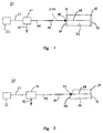
- Figure 1 is a first schematic drawing of a rare-earth doped, lithium niobate DBR laser according to a first embodiment of the present invention;
- Figure 2 is a second schematic drawing of a rare-earth doped, lithium niobate DBR laser according to the first embodiment of the present invention;
- Figure 3 is a first schematic drawing of a rare-earth doped, lithium niobate DBR laser according to a second embodiment of the present invention;
- Figure 4 is a second schematic drawing of a rare-earth doped, lithium niobate DBR laser according to the second embodiment of the present invention;
- Figure 5 is a first schematic drawing of a rare-earth doped, lithium niobate DBR laser according to a third embodiment of the present invention;
- Figure 6 is a second schematic drawing of a rare-earth doped, lithium niobate DBR laser according to the third embodiment of the present invention;
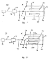
- Figure 7 is a schematic drawing of the first embodiment of the rare-earth doped, lithium niobate DBR laser of the present invention including a phase modulator;
- Figure 8 is a schematic drawing of the first embodiment of the rare-earth doped, lithium niobate DBR laser of the present invention including an amplitude modulator; and
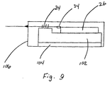
- Figure 9 is a side view of a housing package for the rare-earth doped, lithium niobate DBR laser of the present invention.
- Reference will now be made in detail to the presently preferred embodiments of the invention, examples of which are illustrated in the accompanying drawings.
- Wherever possible, the same reference numbers will be used throughout the drawings to refer to the same or like parts.
- In accordance with the present invention, a laser comprises a substrate of lithium niobate doped with at least one rare earth element, the doped substrate having first and second ends, the first end including a feedback element; a waveguide within the doped substrate; and a grating reflector having an input affixed directly to the second end of the doped substrate and an output, the grating reflector being formed from portions of an optical fibre and reflecting at least the emission signal toward the first end of the doped substrate, the grating reflector and the feedback element defining the doped substrate and the optical fibre as a cavity for the laser.
- The exemplary embodiment of the laser of the present invention is shown in Fig. 1 and is designated generally by
reference numeral 20. - As herein embodied,
laser diode 22 serves as a source of pumping light energy for the laser generally referred to at 20. Thelaser diode 22 feeds the pumping light through anoptical waveguide 23, a wavelength division multiplexer (briefly called WDM in the foregoing) 41, a secondoptical waveguide 44, agrating reflector 24, and intowaveguide 28 within a dopedsubstrate 26. - The
laser diode 22 may be of any type readily available in the marketplace based on the parameters of the overall DBR laser discussed herein. - A suitable laser is 1480 nm Laser Diode Module type FOL1402PAZ-P, Type 4, produced by THE FURUKAWA ELECTRIC Co. Ltd, Tokyo (JP).
- As readily known in the art, the required output power of the diode laser depends on, among other factors, the threshold pumping power required to generate lasing within the laser cavity. In addition, the optimal operating wavelength of the
pump 22 depends on the gain medium within the optical resonator. - In case of erbium as dopant, pump 22 operates preferably at 1480 nm.
-
Laser 20 of Fig. 1 further includes a wavelength division multiplexer (WDM) 41. -
Laser diode 22 provides optical energy along anoptical fibre 23 toWDM 41. - The WDM is a device, known in the art, which combines or separates selected wavelengths from multiple input signals.
- A suitable WDM is, for example, model FWDM 1480/1550 Filter Wavelength Division Multiplexer, manufactured by E-TEK DYNAMICS Inc, San Jose, CA (USA).
-
WDM 41 serves to separate the desired emission signal received online 44 from the pumping signal introduced by thelaser source 22 online 23 and to output the result online 42. - As a result,
output 42 from theWDM 41 functions as an output from theoverall laser 20 in the configuration of Fig. 1. - With respect to the pumping signal,
WDM 41 simply passes the pumping energy fromline 23 toline 44 toward dopedsubstrate 26 with minimal attenuation. - The
laser 20 may use an optical circulator instead of the wavelength division multiplexer to extract the emission signal from the laser. - An optical circulator is a passive optical component, generally provided with three or four ports disposed in an orderly sequence, unidirectionally transmitting the input radiation from each of the ports towards one alone of the other ports and more particularly towards the next adjacent port in the sequence. The optical circulators are commercially available components. Adapted for use in the present invention are for example model CR1500, manufactured by JDS FITEL Inc., 570 Heston Drive, Nepean, Ontario (CA), or model PIFC-100 manufactured by E-TEK DYNAMICS Inc.
- Both the optical circulator and the WDM are preferably connected to the optical circuit by polarization maintaining fibers. Also the grating can be made in a polarization mantaining fiber. If polarization maintaining fibers were not used, a polarization controller should be used.
- The
substrate 26 comprises a crystal of lithium niobate (LiNbO3) doped with at least one rare earth element, for example erbium or neodymium. For an erbium-doped lithium niobate crystal (Er:LiNbO3), thelaser diode 22, as mentioned, provides a pumping energy that centers preferably on a wavelength of 1480 nm, which is a characteristic excitation wavelength for erbium doped lithium niobate. - As known to one of ordinary skill in the art, the use of other rare earth dopants for the LiNbO3 crystal dictates the wavelength of the pumping signal generated by the
laser diode 22. - As shown in Fig. 1, the doped
substrate 26 includes two end faces 31 and 32. Awaveguide 28 formed within the lithium niobate crystal passes the pumping signal generated by thelaser diode 22 through the dopedsubstrate 26, between the substrate end faces 31 and 32. - Preferably, the lithium niobate substrate includes a waveguide which is single mode both at pump and signal wavelengths.
- One end face 31 of the doped
substrate 26 includes anantireflective layer 39 formed thereon. Thislayer 39 minimizes reflections otherwise caused by the interface of thesubstrate end 31 with an optically conductive medium. - Preferably, the
antireflective layer 39 comprises multiple alternating layers of SiO2 and TiO2 applied to thepolished endface 31 of thelithium niobate crystal 26. - Preferably, the
antireflective layer 39 may comprise two layers of SiO2 of about 73 and 78 nm thickness respectively and one layer of TiO2 of about 74 nm thickness interposed therebetween. - The layers may be applied by electron beam evaporation.
- The laser of the preferred embodiment further includes a
feedback element 38 positioned on theother end 32 of the dopedsubstrate 26. - The
feedback element 38 has reflective characteristics such that it will reflect selected optical wavelengths travelling through thewaveguide 28 fromsubstrate end 31 back in the direction ofsubstrate end 31. - The
feedback element 38 serves to reflect at least the emission signal, and preferably the emission signal and the pumping signal, that travels through thewaveguide 28 back through the doped substrate. - The
feedback element 38 is preferably formed directly on theend 32 of the dopedsubstrate 26. This integral structure with thesubstrate 26 eliminates reflections that otherwise would arise with thefeedback element 38 coupled to thesubstrate 26 via an optical connecting device, such as an optical fibre. - Typically, the
feedback element 38 is a broadband mirror with a reflectivity centered around a wavelength within the emission wavelength range, which is about 1530-1610 nm for an erbium-doped lithium niobate crystal (for example, about 1550 nm). - For this construction, a mirror which has, for example, approximately 92% reflectivity at 1550 nm is made of eleven alternating layers of SiO2 and TiO2 of about 262 nm and 183 nm thickness respectively.
- Otherwise, the feedback element might be a wavelength-selective device, i.e. a device which has, for example, a reflectivity of 99% at the emission wavelength of 1550 nm and a reflectivity of 10% a pumping wavelength of 1480 nm.
- Such a wavelength-selective device may be made of 23 alternating layers of SiO2 and TiO2 of about 290 nm and 202 nm thickness respectively.
- In this case, however, only the signal would be reflected, and a single pump pass would be provided.
- Although an integral formation with the
substrate 26 for thefeedback element 38 is preferred, the present invention might also contemplate the positioning of the reflectingelement 38 spaced apart from thesubstrate 26 and connected to the substrate end face 32 with a high coupling efficiency. - In accordance with the present invention, the laser of the preferred embodiment further includes a
grating reflector 24 having an input coupled to end 31 of the dopedsubstrate 26. - The grating is preferably formed in an optical fibre portion, according to techniques known in the field.
- Gratings adapted for use in the present invention are, for example, the so-called Bragg-grating waveguide filters.
- They reflect the radiation in a narrow wavelength band and transmit the radiation outside of this band. They consist of a portion of an optical fibre along which the refractive index exhibits a periodic variation: if the signal portions reflected at each index change are in phase with each other, a constructive interference occurs and the incident signal is reflected.
- The constructive-interference condition, corresponding to the reflection maximum, is expressed by the equation

- The periodic variation in the refractive index in the fiber can be achieved by known techniques, for example by exposing an optical fibre portion devoid of the protective coating to the interference fringes formed by an intense UV beam (such as that generated by an excimer laser, a frequency-doubled argon laser or a frequency-quadrupled Nd:YAG laser) which is caused to interfere with itself by an appropriate interferometer system, by a silicon phase mask for example, as described in US Patent 5,351,321.
- The fibre and in particular the core are thus exposed to a UV radiation of a periodically-varying intensity along the optical axis. In the core portions reached by the UV radiation a partial breaking of the Ge-O bonds occurs, which causes a permanent modification in the refractive index.
- By selecting the grating pitch so to verify the constructive interference condition, the centre wavelength of the reflected band can be determined as desired.
- By this technique, it is possible to produce filter gratings having a -3 dB reflected wavelength band typically of 0.2 ÷ 0.3 nm only, a reflectivity in the middle of the band up to 99%, a central wavelength of the reflected band that can be determined during the manufacturing step within about ± 0.1 nm and a variation with temperature of the central wavelength of the reflected band as low as 0.02 nm/°C.
- In case a larger reflected band would be required, the grating can be made "chirped", that is with non constant pitch along its length.
- The grating 24 transmits the pumping signal and reflects at least the emission signal that emanates from the doped
substrate 26 back into the substrate and towardend 32. Thus, the index variation pitch of the fibre grating 24 is selected such that the grating reflects a wavelength corresponding to one of the peaks in the emission range of the erbium-doped lithium niobate crystal (for example, about 1550 nm). - For a laser that has single-mode, continuous wave operation, the fibre grating 24 also has a narrow bandwidth, preferably less than 1 nm. As a result, the grating 24 and the
feedback element 38 define a cavity for thelaser 20, whereby the emission signal oscillates between the two elements and through the dopedsubstrate 26. - The optical fiber 24a, in which the
grating 24 has been made, is affixed directly to theend 31 of the doped substrate as a pigtail, according to a technique known in the art, in a way to minimize interface reflections when light travels between them. - In a preferred embodiment, as schematically shown in Fig. 1, a
ferrule 34, or an equivalent element, helps to secure the fibre including the grating 24 to the dopedsubstrate 26, in optical connection with thewaveguide 28. - In the following, the fiber 24a and the grating 24 included thereinto will be indicated, in short, as "grating 24".
- This
devices 34 provides stability for the coupling of the grating 24 with thewaveguide 28. - The grating 24 may then be affixed with the
waveguide 28 such that the waveguide and fibre end of the grating abut. - In particular, the coupling of the grating 24 with
waveguide 28 is preferably made in the following manner. - The grating 24 is inserted into a corresponding seat in the
ferrule 34 and positioned such that the end of the grating 24 and the end of theferrule 34 align axially. - The two items are then secured together using a glue or other adhesive or securing composition or apparatus.
- The end of the ferrule-fibre grating unit and the waveguide endface are then both polished before coupling them together.
- Next, the ferrule-grating unit is positioned near the waveguide endface where the transmitted power between the waveguide and the grating is optimized, and the two endfaces are secured together using a transparent glue.
- Typically, the insertion loss of such a connection between the fibre grating and the waveguide is 0.5 dB per interface.
- Hence, the cavity defined by the grating 24 and the
feedback element 38 comprises essentially the dopedsubstrate 26 and the short portion of the optical fibre 24a included between thesubstrate end 31 and thefibre grating 24. - The fiber 24a is then optically coupled with a
fiber 44 of aWDM 41, for example by butt welding. - The oscillating emission within the laser cavity which will escape from the grating will pass through
fibre 44 to theWDM 41. As discussed,WDM 41 will separate this desired emission signal and output the signal throughfibre 42. - As can be seen, the configuration of
laser 20 has several distinct advantages. - The simple structure of the doped
lithium niobate crystal 26 and the fibre grating 24 permits an inexpensive and easy assembly for a laser cavity. Both components may be arranged together with a single optical connection between the fibre grating 24 and thewaveguide 28, using theferrule 34 or an equivalent pigtailing device. - Consequently, the laser cavity may be attached to the
pigtail fibre 44 of aWDM 41 or removed as needed with little encumbrance. - Also, the use of a fibre grating 24 rather than a grating etched within the lithium niobate substrate greatly simplifies fabrication of the laser cavity.
- Further, the laser configuration of Fig. 1 has much lower noise and pump signal loss than prior arrangements.
- In particular, the laser cavity attached to
pigtail fibre 44 of theWDM 41 has only one interface in its conducting medium, which occurs between fibre grating 24 andwaveguide 28 of thesubstrate 26. - The connection between these waveguides is arranged to produce as little loss as possible, generally around 0.5 dB of attenuation, for signals passing across the interface.
- The presence of a single interface is made possible due to the incorporation of
feedback element 38 directly on thelithium niobate substrate 26. - Also, potential noise-inducing or signal-attenuating devices, such as
WDM 41, are positioned outside the laser cavity. - As a result, the
laser 20 of Fig. 1 has lower attenuation and lower noise than prior arrangements, which permits the use of a lower-powered laserdiode pump source 22. - It should be noted that lower-powered laser diode pump sources are less-expensive and will provide higher reliability and longer operating life in comparison with higher powered ones.
- Moreover, the
laser 20 improves over prior arrangements in that it supplies two-way pumping to the gain medium of the dopedsubstrate 26. - As mentioned, the pump signal from
laser diode 22 passes into the dopedsubstrate 26 viaend face 31. The pump signal then travels through the doped medium of the lithium niobate crystal and causes lasing and stimulated emission. - The pump signal reflects off
feedback element 38, preferably without leaving the dopedsubstrate 26, and passes back through the substrate towardend 31. - In doing so, the pump signal again passes through the gain medium of the
substrate 26 and further stimulates lasing within the cavity. - This two-way pumping of the cavity provides increased efficiency for the
laser 20 and additionally enables the use of a lower-powered laserdiode pump source 22. - Because the reflective wavelength of the fibre grating 24 may fluctuate with temperature, thereby causing a corresponding fluctuation in the output wavelength of the
laser 20, a container or package may house several or all of the components of thelaser 20. - Fig. 9 illustrates a side view of a preferred packaging arrangement for
laser 20. - As shown in Fig. 9, the
lithium niobate substrate 26 is mounted on acopper submount 102. - The submount forms the base for the fibre grating 24 as well, and thereby provides mechanical stability for the laser cavity between the grating 24 and the doped
substrate 26. - A thermistor and
Peltier element 104, positioned under thecopper submount 102, monitor and control the temperature on thesubmount 102 to a stabilized, predetermined value. - Optimally, the thermistor and Peltier element stabilizes the cavity temperature to ± 0.1°C.
- Typically, a thermally-secure container 106 covers at least the
doped substrate 26 and the fibre grating 24, as well as thesubmount 102 and thermistor andPeltier element 104. - Additionally, the laser container 106 housing the laser cavity may be inserted into a larger package (not shown) that includes the WDM, pump source, and related electronic circuits that drive the pump source and the Peltier element.
- In this way, the temperature surrounding the fibre grating 24 will remain stable despite the external environment in which the laser package is used, and the reflective wavelength for the grating will remain consistent.
- Referring to Fig. 2, a variation of the first embodiment of the present invention comprises a laser, generally referred to at 30, that has a doped LiNbO3 substrate with an
end face 48 polished at an angle. - This
angled end face 48 is the end of the substrate located opposite from thefeedback element 38. - Likewise, the fibre grating 24 that optically couples with the
end face 48 viaferrule 34 has a polished end that matches with the angle of thesubstrate end face 48. - The angled cut of the
end 48 and fibre grating 24 provides an optical connection without giving rise to detrimental reflections. - The
angled end 48 thus avoids the need for adding an antireflective layer between the substrate end and the fibre grating 24 and achieves substantially the same result of minimizing reflections at the substrate-grating interface. - A typical angle in the lithium niobate substrate is about 6°, and a corresponding angle in the ferrule is about 8.5°; generally, these values can be selected to minimize the reflection and to provide optimal coupling, in dependance of the respective refractive indexes of the optical means to be optically connected together, according to principles known to the skilled in the art.
- Fig. 3 illustrates a second embodiment of the present invention.
- According to the second embodiment of the present invention, a laser, generally referred to as 40, comprises a
laser diode 22, a fibre grating 24, a rare-earth doped LiNbO3 substrate 26, and a wavelength division multiplexer (WDM) 41. - In this arrangement of Fig. 3, the
WDM 41 is coupled to theend 32 of the dopedsubstrate 26, rather than between thelaser diode 22 and the fibre grating 24 as shown in Fig. 1. - The
WDM 41 oflaser 40 is coupled to the dopedsubstrate end 32 by way ofoptical fibre 46. - The
fibre 46 andwaveguide 28 are optically connected together using a pigtailing means including aferrule 36, or an equivalent device. - As discussed above with reference to the
ferrule 34, used fro the connection between thewaveguide 28 and the fibre grating 24, theferrule 36 is adhered to thelithium niobate crystal 26 and securesfibre 46 andwaveguide 28 in abutment with substantial axial alignment, to provide suitable optical connection. - As with
laser 20 of Fig. 1,laser 40 of Fig. 3 usesWDM 41, and specifically itsoutput fibre 42, as the output to the overall laser. -
WDM 41 separates in itsoutput fiber 44 the residual pumping signal generated bylaser diode 22 and received atfibre 46, from the emission signal also received atfibre 46 and outputted infiber 42. - The
laser 40 operates as follows. -
Laser diode 22 generates a pump signal of a selected wavelength and power that is characteristic of the rare-earth dopant in the lithium niobate crystal. - The pump signal travels through undoped
optical fibre 23 and fibre grating 24 and enters the dopedsubstrate 26 atend 31. -
Ferrule 34 assists in securing a connection of abutment, and preferably physical contact, between the fibre grating 24 andwaveguide 28, so as to provide a suitable optical coupling. -
Substrate end 31 includes anonreflective coating 39 that assists in minimizing any interface reflections across the grating-substrate interface. - The pump signal passes through doped
substrate 26 and excites the gain medium to lase at stimulated emission wavelength. - A
feedback element 38, described above forlaser 20, formed onsubstrate end 32, reflects both the stimulated emission and the pump signal back through the gain medium for additional stimulation of the gain medium. - The
feedback element 38 preferably comprises a partially reflective mirror or a similar wavelength-selective feedback element, capable of reflecting both the pumping wavelength and the emission wavelength. - The
feedback element 38 can be made with a multi-layer coating of theendface 32 of thesubstrate 26, to provide the desired reflectivity, as already described before. - The parts of the signal at the emission wavelength and of the residual pumping signal that are transmitted through
feedback element 38reach WDM 41 that, as explained, separates the two signals respectively towardsoutput fibers - The
fibre grating 24 is made in compliance with the already given equation
- As a result, the emission signal stimulated by the pump signal will oscillate between fibre grating 24 and
feedback element 38, which two elements define the cavity forlaser 40. - The lithium niobate DBR laser of Fig. 3 thereby exhibits some of the same enhanced properties of
laser 20. - The arrangement of
feedback element 38 onsubstrate end 32 permits two-way pumping of the gain medium of the lithium niobate crystal. - As well, the compact design having no devices positioned within the laser cavity helps to minimize laser noise and raise efficiency.
- As a result, the configuration for
laser 40 enables the use of a lower-poweredlaser diode 22 to achieve lasing in the doped lithium niobate crystal. - An experiment was performed using the arrangement depicted in Fig. 3, with the exception that
substrate end 32 andWDM 41 were coupled together using a lens system rather than a fibre pigtailing system. - In this setup, the erbium doped lithium niobate crystal substrate was butt-coupled with a fiber grating, having a peak of reflectivity at 1546.9 nm.
- The erbium doped lithium niobate substrate was a z-cut lithium niobate crystal about 60 mm long, 5 mm large and 1 mm thick; erbium doping was with the deposition of a 15 nm thick erbium layer using electron beam evaporation, followed by a diffusion treatment for about 100 hours at 1100°C, to provide a superficial erbium concentration of about 1020 atoms/cm3.
- A waveguide was subsequently made in the substrate by photolitographic definition of a Ti stripe 6 µm wide and 120 nm thick, followed by a diffusion treatment for about 9 hours at 1030°C. 1/e2 mode field diameter of the waveguide was 10.98x8.08 µm in TE polarization and 8.31x6.47 µm in TM polarization.
- Cut-off wavelength was 1370 nm and 1220 nm for TM and TE polarizations respectively.
- The
feedback element 38 in the test arrangement comprised a partially-reflecting mirror of the dielectric multilayer type. - The laser modes were detected using a Fabry-Perot interferometer with a 7.5 GHz spectral range.
- The results of this experiment confirmed the operation of the DBR laser in a single longitudinal mode.
- The following results were obtained:
- Emission signal wavelength:
- 1546.9 nm
- Operating threshold of laser:
- 40.2 mW
- Laser efficiency:
- 2.5%
- Referring to Fig. 4, a variation of the second embodiment of the present invention comprises a laser generally referred to at 50 that has a doped LiNbO3 substrate with an
end 48 polished at an angle. Thisangled end 48 is the end of the substrate located opposite from thefeedback element 38. Likewise, the fibre grating 24 that couples with theend 48 viaferrule 34 has a correspondingly polished end that matches with the angle of the substrate end 48 (the relevant refractive indexes of the two materials having been taken into account). - The polishing of the
end face 48 and fibre grating 24 provides an optical connection without giving rise to detrimental reflections. - The
angled end 48 thus can avoid the need for adding an antireflective coating between the substrate end and the fibre grating 24 and achieves substantially the same result of minimizing reflections at the substrate-grating interface. - In accordance with the present invention, a third embodiment of the present invention comprises a laser diode, a rare-earth doped lithium niobate substrate, two fibre gratings, and a wavelength division multiplexer (WDM).
- As embodied herein and generally referred to at 60 in Fig. 5, the laser includes a laser
diode pump source 22 coupled to a rare-earth dopedlithium niobate crystal 26 via an undopedoptical fibre 23. - In contrast to previous embodiments, the embodiment of laser 60 has the doped
substrate 26 positioned between thelaser diode 22 andfibre grating 24. In addition,substrate end 32 andfeedback element 38 face thepump source 22 and receive the pumping signal therefrom. - Laser 60 in Fig. 5 operates as follows.
-
Laser diode source 22 generates pumping energy that travels alongoptical fibre 23, throughfeedback element 38 and enterswaveguide 28 of the dopedsubstrate 26. - As with previous embodiments, the connection with
waveguide 28 preferably occurs by way of pigtailing means including aferrule 36 and abutment offibre 23 withwaveguide 28. - The pump signal travels through
waveguide 28, stimulating emission from the gain medium within the dopedsubstrate 26. -
Substrate end 31 includes an antireflective coating orsurface 39 that minimizes reflections and noise as light crosses the substrate border. The pumping energy exits the dopedsubstrate 26 atend 31 and passes through a first fibre grating 24 to second fibre grating 62. - The second fibre grating 62 is made in a known fashion such that the
device 62 selectively reflects the pumping signal back toward the dopedsubstrate 26. The pumping signal enters the doped substrate again throughend 31 and thereby makes a second pass through the gain medium of the crystal. -
Feedback element 38 of the present invention reflects the emission stimulated by the pump signal in laser 60 back into the dopedsubstrate 26. -
Feedback element 38 for this embodiment is preferably a wavelength-selective device, such as a multi-layer reflective coating of the type described before, positioned at the end of thesubstrate 26, that has low reflectivity for the pumping wavelength and high reflectivity for the emission wavelength. - In particular, a wavelength-selective feedback element which has, for example, a reflectivity of 99% at the emission wavelength of 1550 nm and a reflectivity of 10% a pumping wavelength of 1480 nm, may be made of 23 alternating layers of SiO2 and TiO2 of about 290 nm and 202 nm thickness respectively.
- The
feedback element 38 reflects the emission signal stimulated by the pumping signal. - Fibre grating 24, affixed to the
substrate end 31 and to the second fibre grating 62, is designed so that it selectively reflects a selected wavelength of the stimulated emission of the lithium niobate dopant. - As a result, the emission within the doped
substrate 26 will reflect off thefeedback element 38 within the substrate and the fibre grating 24 outside the substrate and oscillate in between these surfaces. Thus, thefeedback element 38 and the fibre grating 24 define the cavity for laser 60. -
WDM 41 in laser 60 is connected through itsinput port 46 to the second fibre grating 62. - The
WDM 41 will receive some of the emission signal and the pumping signal onfibre 46 and will separate the emission signal toline 42 and the pumping signal toline 44. -
Output fiber 42 in laser 60 functions as the overall output for the laser. - Laser 60 provides a laser configuration that enables two-way pumping of the laser cavity with low noise and reflections. As with previously discussed embodiments, laser 60 benefits from the single interface at
substrate end 31 within the laser cavity. - A high coupling efficiency and low loss across this interface provides laser 60 with low noise and reflections and yet allows inexpensive and easy fabrication of the grating in an optical fibre, as shown at 24.
- Referring to Fig. 6, a variation of the third embodiment of the present invention comprises a laser generally referred to at 70 that has a doped LiNbO3 substrate with an
end face 48 polished at an angle. - This
angled end face 48 is the end of the substrate located opposite from thefeedback element 38. - Likewise, the fibre grating 24 that couples with the
end face 48 viaferrule 34 has a cleaved end that matches with the angle of thesubstrate end face 48. - The angled polishing of the
end face 48 and fibre grating 24 provides an optical connection without substantially giving rise to detrimental reflections. - The
angled end face 48 thus may avoid the need for adding an antireflective coating between the substrate end face and the fibre grating 24 and achieves substantially the same result of minimizing reflections at the substrate-grating interface. - According to the present invention, each of the above-described preferred embodiments may further include additional elements as required to optimize the performance or simplicity of the invention, and to provide extra functionalities.
- In particular,
lasers - Referring to Fig. 7, as an example, a
laser 80 includes alaser pump source 22, aWDM 41, alithium niobate substrate 26 doped with a rare earth material such as erbium, and afibre grating 24. - As previously discussed, an
optical waveguide 28 passes a pumping signal and an emission signal through the dopedsubstrate 26. - A
feedback element 38, such as a mirror or other reflective element or treatment, reflects the pump wavelength back through the dopedsubstrate 26. The configuration of Fig. 7, however, also utilizes the excellent electrooptical properties of LiNbO3 for a monolithic integration of an intracavity phase modulator for FM mode-locking. - The
laser 80 of Fig. 7 illustrates a configuration of the present invention that achieves FM mode-locking using an intracavity phase modulator. - The phase modulator generally referred to at 82 is integrally formed in the LiNbO3 substrate.
- In the illustrated embodiment, the substrate is made of a x-cut LiNbO3 crystal and the
phase modulator 82 compriseselectrodes 84 and 86 positioned on opposite sides ofwaveguide 28, which extends through the dopedsubstrate 26. - Electrode 86 is connected with ground in a known manner.
- A sinusoidal signal from, for example, an RF signal generator (not shown), drives the
intracavity phase modulator 82 throughelectrode 84. - The sinusoidal signal has a frequency equal to the free spectral range of the laser cavity, or a harmonic thereof. This selected frequency will achieve mode-locking for a single circulating optical pulse in the cavity, or a number of pulses equal to the number of harmonics of the sinusoidal frequency.
- The pulse generated by the
laser 80 when operating in a mode-locking regime is transform limited, where the pulse (duration * bandwidth) = 0.442. - As a result, any variation in the spectral bandwidth of the emission signal causes a corresponding change in the pulse duration. That is, if the spectral bandwidth of the emission signal increases (decreases), the duration of the mode-locking pulse correspondingly decreases (increases).
- In the configuration of Fig. 7, the fibre grating 24 has a predetermined bandwidth as a feedback element for the
laser 80, preferably less than 1 nm. With a fixed emission wavelength, it is therefore possible to reduce the spectral content of the optical pulse in the cavity and cause an enlargement of the time duration of the pulse. By discriminately selecting the characteristics of fibre grating 24 for a desired bandwidth, a fixed and determinable pulse duration for the mode-locked laser can be obtained. - In accordance with a further embodiment of the present invention, a laser generally referred as 90 in Fig. 8 includes a
laser pump source 22, aWDM 41, alithium niobate substrate 26 doped with a rare earth material such as erbium, and afibre grating 24. - The configuration of Fig. 8, however, also utilizes the excellent electrooptical properties of LiNbO3 for a monolithic integration of an intracavity amplitude modulator for AM mode-locking.
- The amplitude modulator, generally referred to at 92 in Fig. 8, is integrally formed in the LiNbO3 substrate and includes
electrodes - In this arrangement, a section of the straight waveguide within the lasing cavity is replaced with a Mach Zehnder modulator.
-
Electrodes - As with the phase modulator in Fig. 7, a sinusoidal signal from, for example, an RF signal generator (not shown) drives the amplitude modulator in Fig. 8.
- The signal generator drives the sinusoidal signal through
electrode 96. - The sinusoidal signal has a frequency equal to the free spectral range of the laser cavity, or a harmonic thereof.
- This frequency will achieve AM mode-locking with a single circulating optical pulse in the cavity, or a number of pulses equal to the number of harmonics of the frequency.
- As with the phase modulator for FM mode-locking, if the spectral bandwidth of the emission signal increases (decreases), the duration of the mode-locking pulse with the amplitude modulator correspondingly decreases (increases).
- In the configuration of Fig. 8, the fibre grating 24 has a predetermined bandwidth as a reflective element for the
laser 90, preferably less than 1 nm. By discriminately selecting the characteristics of fibre grating 24 for a desired bandwidth, a fixed and determinable pulse duration for the mode-lockedlaser 90 can be attained. Hence, optimizing the spectral width of the fibre grating will assist in optimizing the width of pulses circulating in the cavity. - In the preceeding description the substrate in which the waveguide is made was described making reference to its preferred embodiment, where a of lithium niobate substrate is used; however, it is apparent to the skilled in the art that other substrates can be used to make a laser, if appropriate. In particular, other electro-optic materials can be used, such as lithium tantalate or lithium iodate or electro-optic polymers.
- In addition, in case electro-optic properties were not required in a specific application, other materials dopable with lasing ions can be used, such as SiO2 or other glass compositions, without departing from the present invention.
- It will be apparent to those skilled in the art that various modifications and variations can be made to the present invention without departing from the spirit or scope of the invention.
- For example, the intracavity phase modulator of Fig. 7 and the intracavity amplitude modulator of Fig. 8 shown for the laser arrangement of Fig. 2 may equivalently be applied to the other laser arrangements described before, i.e. those shown in Figs. 1 and 3 to 6.
- Thus, it is intended that the present invention covers any modifications and variations provided they come within the scope of the appended claims and their equivalents.
Claims (35)
- A laser, comprising:― a substrate doped with a lasing material, the doped substrate having first and second ends and including a waveguide for passing a pumping light and a stimulated emission signal between the ends, the first end including a feedback element for reflecting at least a portion of the emission signal toward the second end; and― a grating reflector having an input optically coupled with the waveguide at the second end of the doped substrate and an output, the grating reflector and the feedback element defining a laser cavity including the doped substrate, characterized in that the grating reflector is formed from an optical fibre portion and reflects at least a portion of the emission signal toward the first end of the doped substrate.
- The laser of claim 1, characterized in that it further comprises a pump source coupled to the output of the grating reflector, the pump source driving pumping light through the grating reflector and then into the doped substrate.
- The laser of claim 2, characterized in that it further comprises optical separation means interposed between the pump source and the grating reflector, the optical separation means separating the emission signal from other signals received from the pump source and the grating reflector.
- The laser of claim 2, characterized in that it further comprises a wavelength division multiplexer optically coupled to the first end of the doped substrate, the wavelength division multiplexer separating the emission signal from other signals received from the feedback element.
- The laser of claim 3, characterized in that said optical separation means is a wavelength division multiplexer.
- The laser of claim 3, characterized in that said optical separation means is an optical circulator.
- The laser of claim 1, characterized in that said substrate is an electro-optic material.
- The laser of claim 1, characterized in that said substrate is lithium niobate.
- The laser of claim 1, characterized in that said lasing material includes at least a rare earth.
- The laser of claim 1, characterized in that said feedback element reflects at least a portion of both the emission signal and the pumping light toward the second end of the substrate.
- The laser of claim 1, characterized in that it further comprises a thermally-stable package housing at least the doped substrate and the grating reflector.
- The laser of claim 1, characterized in that the optical connection between the grating reflector and the doped substrate causes a loss to the pumping light of less than 1 dB.
- The laser of claim 1, characterized in that the feedback element comprises a plurality of layers of dielectric material deposited on the first end of the doped substrate.
- The laser of claim 1, characterized in that the second end of the doped substrate includes an antireflective coating.
- The laser of claim 1, characterized in that the second end of the doped substrate is polished at an angle.
- The laser of claim 1, characterized in that it further comprises a pump source coupled to the first end of the doped substrate, the pump source driving pumping light through the feedback element, the doped substrate, and then to the grating reflector.
- The laser of claim 15, characterized in that it further comprises a wavelength division multiplexer coupled to the output of the grating reflector, the wavelength division multiplexer separating the emission signal from other signals received from the grating reflector.
- The laser of claim 1, characterized in that the emission signal corresponds to single-mode, continuous-wave operation for the laser.
- The laser of claim 1, characterized in that the grating reflector has a bandwidth less than 1 nm.
- The laser of claim 7, characterized in that it further comprises a phase modulator integrated in the doped substrate, the phase modulator providing FM mode-locking operation for the laser.
- The laser of claim 7, characterized in that it further comprises an amplitude modulator integrated in the doped substrate, the amplitude modulator providing AM mode-locking operation for the laser.
- A laser, comprising:― a pump source for generating a pumping light;― a substrate of lithium niobate doped with at least one rare earth element, the doped substrate including a waveguide for passing the pumping light and a stimulated emission signal through the doped substrate;― first means, contacting the waveguide, for reflecting a first group of selected wavelengths passing from the waveguide back through the waveguide, the first group including at least the emission signal;― second means, contacting the waveguide, for reflecting a second group of selected wavelengths passing from the waveguide back through the waveguide, the doped substrate being positioned between the first and second reflecting means, the second group including at least the pumping signal; and― a grating reflector having an input coupled to the second reflecting means and an output, the grating reflector being formed from portions of an optical fibre and reflecting at least the emission signal passing from the second reflecting means back toward the waveguide, the grating reflector and the first reflecting means defining a cavity for the laser.
- The laser of claim 22, characterized in that it further comprises a thermally-stable package housing at least the doped substrate and the grating reflector.
- The laser of claim 22, characterized in that the grating reflector is positioned between the second wavelength-selective reflector and the doped substrate, the input of the grating reflector being optically coupled to the second end of the doped substrate.
- The laser of claim 24, characterized in that it further comprises a wavelength division multiplexer coupled to the second wavelength-selective reflector, the wavelength division multiplexer separating the emission signal from other signals received from the feedback element.
- The laser of claim 22, characterized in that the second wavelength-selective reflector is positioned between the grating reflector and the doped substrate, the second wavelength-selective reflector abutting the second end of the doped substrate.
- The laser of claim 26, characterized in that it further comprises a wavelength division multiplexer coupled to the output of the grating reflector, the wavelength division multiplexer separating the emission signal from other signals received from the feedback element.
- The laser of claim 22, characterized in that the emission signal corresponds to single-mode, continuous-wave operation for the laser.
- The laser of claim 22, characterized in that the grating reflector has a bandwidth less than 1 nm.
- The laser of claim 29, characterized in that it further comprises a phase modulator integrated in the doped substrate, the phase modulator providing FM mode-locking operation for the laser.
- The laser of claim 29, characterized in that it further comprises an amplitude modulator integrated in the doped substrate, the amplitude modulator providing AM mode-locking operation for the laser.
- A laser, comprising:― a pump source for generating a pumping light;― a substrate of lithium niobate doped with at least one rare earth element, the doped substrate including a waveguide for passing the pumping light and a stimulated emission signal through the doped substrate;― a first wavelength-selective reflector contacting the waveguide for reflecting a first group of selected wavelengths passing from the waveguide back through the waveguide, the first group including at least the emission signal;― a second wavelength-selective reflector contacting the waveguide for reflecting a second group of selected wavelengths passing from the waveguide back through the waveguide, the doped substrate being positioned between the first and second wavelength-selective reflectors, the second group including at least the pumping signal;― a first grating reflector having an input coupled to the second wavelength-selective reflector and an output; and― a second grating reflector having an input coupled to the output of the first grating reflector, the first and second grating reflectors being formed from portions of optical fibres, one of the first and second grating reflectors reflecting the emission signal passing from the second wavelength-selective reflector back toward the waveguide, another of the first and second grating reflectors reflecting the pumping signal passing from the second wavelength-selective reflector back toward the waveguide, the first wavelength-selective reflector and said one of the first and second grating reflectors defining a cavity for the laser.
- The laser of claim 32, characterized in that the grating reflector has a bandwidth less than 1 nm.
- The laser of claim 33, characterized in that it further comprises a phase modulator integrated in the doped substrate, the phase modulator providing FM mode-locking operation for the laser.
- The laser of claim 33, characterized in that it further comprises an amplitude modulator integrated in the doped substrate, the amplitude modulator providing AM mode-locking operation for the laser.
Priority Applications (8)
| Application Number | Priority Date | Filing Date | Title |
|---|---|---|---|
| EP96830008A EP0784362B1 (en) | 1996-01-12 | 1996-01-12 | Rare-earth doped lithium niobate DBR laser |
| DE69626950T DE69626950D1 (en) | 1996-01-12 | 1996-01-12 | Rare earth doped lithium niobate DBR laser |
| US08/760,735 US5796764A (en) | 1996-01-12 | 1996-12-05 | Rare-earth doped lithium niobate DBR laser |
| ARP970100092A AR005425A1 (en) | 1996-01-12 | 1997-01-10 | LASERS USING BRAGG REFLECTORS DISTRIBUTED OF RARE EARTH LITHIUM NIOBATE DOPED |
| CA002194821A CA2194821C (en) | 1996-01-12 | 1997-01-10 | Rare-earth doped lithium niobate dbr laser |
| NZ314053A NZ314053A (en) | 1996-01-12 | 1997-01-10 | Rare-earth doped lithium niobate laser with optical fibre grating reflector forming one end of lasing cavity |
| AU10124/97A AU734315B2 (en) | 1996-01-12 | 1997-01-10 | Rare-earth doped lithium niobate DBR laser |
| BR9700099A BR9700099A (en) | 1996-01-12 | 1997-01-13 | Rare earth doped lithium niobate dbr laser |
Applications Claiming Priority (1)
| Application Number | Priority Date | Filing Date | Title |
|---|---|---|---|
| EP96830008A EP0784362B1 (en) | 1996-01-12 | 1996-01-12 | Rare-earth doped lithium niobate DBR laser |
Publications (2)
| Publication Number | Publication Date |
|---|---|
| EP0784362A1 true EP0784362A1 (en) | 1997-07-16 |
| EP0784362B1 EP0784362B1 (en) | 2003-03-26 |
Family
ID=8225787
Family Applications (1)
| Application Number | Title | Priority Date | Filing Date |
|---|---|---|---|
| EP96830008A Expired - Lifetime EP0784362B1 (en) | 1996-01-12 | 1996-01-12 | Rare-earth doped lithium niobate DBR laser |
Country Status (8)
| Country | Link |
|---|---|
| US (1) | US5796764A (en) |
| EP (1) | EP0784362B1 (en) |
| AR (1) | AR005425A1 (en) |
| AU (1) | AU734315B2 (en) |
| BR (1) | BR9700099A (en) |
| CA (1) | CA2194821C (en) |
| DE (1) | DE69626950D1 (en) |
| NZ (1) | NZ314053A (en) |
Cited By (8)
| Publication number | Priority date | Publication date | Assignee | Title |
|---|---|---|---|---|
| EP0917262A2 (en) * | 1997-11-10 | 1999-05-19 | Lucent Technologies Inc. | Wavelength selectable laser source |
| FR2776848A1 (en) * | 1998-03-24 | 1999-10-01 | Sagem | Reflective optical modulator especially for a Q-switched fiber laser |
| EP0969310A1 (en) * | 1998-06-04 | 2000-01-05 | PIRELLI CAVI E SISTEMI S.p.A. | Waveguides for use in acousto-optical mode converters and method for making the same |
| WO2000051212A2 (en) * | 1999-01-27 | 2000-08-31 | Northstar Photonics, Inc. | Waveguide lasers |
| US6282332B1 (en) | 1998-06-04 | 2001-08-28 | Pirelli Cavi E Sistemi S.P.A. | Waveguide structures in particular for use in acousto-optical mode converters and method for making same |
| US6493476B2 (en) | 2000-11-27 | 2002-12-10 | Teem Photonics | Apparatus and method for integrated photonic devices having gain and wavelength-selectivity |
| US6718110B2 (en) | 1998-06-04 | 2004-04-06 | Corning Incorporated | Indiffused optical waveguide structures in a substrate |
| US6813405B1 (en) | 2002-03-29 | 2004-11-02 | Teem Photonics | Compact apparatus and method for integrated photonic devices having folded directional couplers |
Families Citing this family (18)
| Publication number | Priority date | Publication date | Assignee | Title |
|---|---|---|---|---|
| US5485481A (en) * | 1994-06-28 | 1996-01-16 | Seastar Optics Inc. | Fibre-grating-stabilized diode laser |
| JPH10307228A (en) * | 1997-05-08 | 1998-11-17 | Nec Corp | Line monitor and optical amplifier using the monitor |
| JPH11119177A (en) * | 1997-10-13 | 1999-04-30 | Oki Electric Ind Co Ltd | Light/time multiplex modulation transmitter module |
| DE60132056T2 (en) * | 2000-03-15 | 2008-12-18 | Sumitomo Osaka Cement Co., Ltd. | OPTICAL WAVE MODULATOR WITH OUTDOOR LIGHT MONITOR |
| US7315697B2 (en) * | 2000-09-26 | 2008-01-01 | Celight, Inc. | Light source for generating an output signal having spaced apart frequencies |
| US6669367B2 (en) * | 2001-10-10 | 2003-12-30 | Applied Optoelectronics, Inc. | Optical fiber with mirror for semiconductor laser |
| US7167490B2 (en) * | 2001-11-05 | 2007-01-23 | Jds Uniphase Corporation | Optical gain apparatus with pump source wavelength control |
| KR100559469B1 (en) * | 2003-06-09 | 2006-03-10 | 한국전자통신연구원 | Gain-clamped optical amplifier |
| US7391795B2 (en) * | 2003-08-01 | 2008-06-24 | Nippon Telegraph And Telephone Corporation | Laser light source |
| US20060239609A1 (en) * | 2005-04-26 | 2006-10-26 | Sorin Wayne V | Methods and apparatuses to increase wavelength channels in a wavelength-division-multiplexing passive-optical-network |
| US7733927B2 (en) * | 2006-06-22 | 2010-06-08 | Panasonic Corporation | Laser light source device and image display device |
| US8564783B2 (en) | 2008-05-15 | 2013-10-22 | Axsun Technologies, Inc. | Optical coherence tomography laser with integrated clock |
| JP2015532536A (en) * | 2012-10-05 | 2015-11-09 | デイビッド ウェルフォード, | System and method for amplifying light |
| US20140198377A1 (en) * | 2013-01-15 | 2014-07-17 | Omron Corporation | Laser oscillator |
| CN103944043A (en) * | 2014-03-20 | 2014-07-23 | 天津欧泰激光科技有限公司 | In-band pumping 975-nanometer single-frequency fiber laser with ytterbium-doped silica optical fiber |
| US10790911B2 (en) * | 2018-04-10 | 2020-09-29 | The University Of Massachusetts | Modified Sagnac loop coherent phase modulated RF photonic link |
| JP7205317B2 (en) * | 2019-03-13 | 2023-01-17 | 住友大阪セメント株式会社 | Optical waveguide element and its manufacturing method |
| CN113904205B (en) * | 2021-09-16 | 2023-04-07 | 上海交通大学 | Optical waveguide chip based on erbium-doped lithium niobate and mode-locked laser |
Citations (2)
| Publication number | Priority date | Publication date | Assignee | Title |
|---|---|---|---|---|
| WO1994022187A1 (en) * | 1993-03-25 | 1994-09-29 | British Telecommunications Public Limited Company | A laser |
| US5450427A (en) * | 1994-10-21 | 1995-09-12 | Imra America, Inc. | Technique for the generation of optical pulses in modelocked lasers by dispersive control of the oscillation pulse width |
Family Cites Families (5)
| Publication number | Priority date | Publication date | Assignee | Title |
|---|---|---|---|---|
| EP0220455A1 (en) * | 1985-09-24 | 1987-05-06 | Siemens Aktiengesellschaft | Arrangement for coupling a laser diode to a monomode waveguide |
| US4787086A (en) * | 1986-05-19 | 1988-11-22 | American Telephone And Telegraph Company, At&T Bell Laboratories | High-power, fundamental transverse mode laser |
| US5295209A (en) * | 1991-03-12 | 1994-03-15 | General Instrument Corporation | Spontaneous emission source having high spectral density at a desired wavelength |
| US5305336A (en) * | 1992-01-29 | 1994-04-19 | At&T Bell Laboratories | Compact optical pulse source |
| US5485481A (en) * | 1994-06-28 | 1996-01-16 | Seastar Optics Inc. | Fibre-grating-stabilized diode laser |
-
1996
- 1996-01-12 DE DE69626950T patent/DE69626950D1/en not_active Expired - Lifetime
- 1996-01-12 EP EP96830008A patent/EP0784362B1/en not_active Expired - Lifetime
- 1996-12-05 US US08/760,735 patent/US5796764A/en not_active Expired - Fee Related
-
1997
- 1997-01-10 AU AU10124/97A patent/AU734315B2/en not_active Ceased
- 1997-01-10 AR ARP970100092A patent/AR005425A1/en not_active Application Discontinuation
- 1997-01-10 CA CA002194821A patent/CA2194821C/en not_active Expired - Fee Related
- 1997-01-10 NZ NZ314053A patent/NZ314053A/en unknown
- 1997-01-13 BR BR9700099A patent/BR9700099A/en active Search and Examination
Patent Citations (2)
| Publication number | Priority date | Publication date | Assignee | Title |
|---|---|---|---|---|
| WO1994022187A1 (en) * | 1993-03-25 | 1994-09-29 | British Telecommunications Public Limited Company | A laser |
| US5450427A (en) * | 1994-10-21 | 1995-09-12 | Imra America, Inc. | Technique for the generation of optical pulses in modelocked lasers by dispersive control of the oscillation pulse width |
Non-Patent Citations (3)
| Title |
|---|
| SOCHTIG J ET AL: "DBR WAVEGUIDE LASER IN ERBIUM-DIFFUSION-DOPED LINBO3", ELECTRONICS LETTERS, vol. 31, no. 7, 30 March 1995 (1995-03-30), pages 551/552, XP000504307 * |
| SUCHE H ET AL: "HARMONICALLY MODE-LOCKED TI:ER:LINBO3 WAVEGUIDE LASER", OPTICS LETTERS, vol. 20, no. 6, 15 March 1995 (1995-03-15), pages 596 - 598, XP000493636 * |
| SUGIMOTO N ET AL: "A YTTERBIUM- AND NEODYMIUM-CO-DOPED YTTRIUM ALUMINUM GARNET-BURIED CHANNEL WAVEGUIDE LASER PUMPED AT 0.81 M", APPLIED PHYSICS LETTERS, vol. 67, no. 5, 31 July 1995 (1995-07-31), pages 582 - 584, XP000520530 * |
Cited By (15)
| Publication number | Priority date | Publication date | Assignee | Title |
|---|---|---|---|---|
| EP0917262A2 (en) * | 1997-11-10 | 1999-05-19 | Lucent Technologies Inc. | Wavelength selectable laser source |
| EP0917262A3 (en) * | 1997-11-10 | 2002-01-30 | Agere Systems Optoelectronics Guardian Corporation | Wavelength selectable laser source |
| FR2776848A1 (en) * | 1998-03-24 | 1999-10-01 | Sagem | Reflective optical modulator especially for a Q-switched fiber laser |
| EP0969310A1 (en) * | 1998-06-04 | 2000-01-05 | PIRELLI CAVI E SISTEMI S.p.A. | Waveguides for use in acousto-optical mode converters and method for making the same |
| US6718110B2 (en) | 1998-06-04 | 2004-04-06 | Corning Incorporated | Indiffused optical waveguide structures in a substrate |
| US6282332B1 (en) | 1998-06-04 | 2001-08-28 | Pirelli Cavi E Sistemi S.P.A. | Waveguide structures in particular for use in acousto-optical mode converters and method for making same |
| US6330388B1 (en) | 1999-01-27 | 2001-12-11 | Northstar Photonics, Inc. | Method and apparatus for waveguide optics and devices |
| WO2000051212A3 (en) * | 1999-01-27 | 2001-09-07 | Northstar Photonics Inc | Waveguide lasers |
| US6636678B1 (en) | 1999-01-27 | 2003-10-21 | Teem Photonics, Inc. | Method and apparatus for waveguide optics and devices |
| US6690873B2 (en) | 1999-01-27 | 2004-02-10 | Teem Photonics | Method and apparatus for waveguide optics and devices |
| WO2000051212A2 (en) * | 1999-01-27 | 2000-08-31 | Northstar Photonics, Inc. | Waveguide lasers |
| US6970494B1 (en) | 1999-01-27 | 2005-11-29 | Teem Photonics, S.A. | Rare-earth doped phosphate-glass lasers and associated methods |
| US6493476B2 (en) | 2000-11-27 | 2002-12-10 | Teem Photonics | Apparatus and method for integrated photonic devices having gain and wavelength-selectivity |
| US6954564B2 (en) | 2000-11-27 | 2005-10-11 | Teem Photonics | Apparatus and method for integrated photonic devices having high-performance waveguides and multicompositional substrates |
| US6813405B1 (en) | 2002-03-29 | 2004-11-02 | Teem Photonics | Compact apparatus and method for integrated photonic devices having folded directional couplers |
Also Published As
| Publication number | Publication date |
|---|---|
| CA2194821A1 (en) | 1997-07-13 |
| DE69626950D1 (en) | 2003-04-30 |
| CA2194821C (en) | 2001-11-20 |
| US5796764A (en) | 1998-08-18 |
| AR005425A1 (en) | 1999-06-23 |
| EP0784362B1 (en) | 2003-03-26 |
| BR9700099A (en) | 1998-09-22 |
| AU1012497A (en) | 1997-07-17 |
| AU734315B2 (en) | 2001-06-07 |
| NZ314053A (en) | 1998-08-26 |
Similar Documents
| Publication | Publication Date | Title |
|---|---|---|
| US5796764A (en) | Rare-earth doped lithium niobate DBR laser | |
| US6636678B1 (en) | Method and apparatus for waveguide optics and devices | |
| US6058128A (en) | Apparatus for providing a stabilized laser source | |
| EP0208189B1 (en) | Optical fiber laser | |
| US6373867B1 (en) | Generation of a wavelength-tunable laser oscillation in a wave-guiding gain medium based on passive mode lock | |
| EP0812484B1 (en) | Polarized fiber laser source | |
| JP4486688B2 (en) | Integrated passive mode-locked fiber laser and its fabrication | |
| EP0923799B1 (en) | Frequency doubled laser with an intracavity nonlinear, quasi-phase matching element | |
| EP1608048A2 (en) | Pulsed laser apparatus and method | |
| EP0150749B1 (en) | Composite cavity laser utilizing an intra-cavity electrooptic waveguide device | |
| US20040196874A1 (en) | Erbium-doped phosphate-glass tunable single-mode fiber laser using a tunable fabry-perot filter | |
| JPH06318751A (en) | Longitudinal mode selection laser | |
| US6289027B1 (en) | Fiber optic lasers employing fiber optic amplifiers | |
| JP4063908B2 (en) | Light source device, optical amplifier, and optical communication system | |
| Chieng et al. | Tunable erbium-doped fiber laser with a reflection Mach-Zehnder interferometer | |
| US5172391A (en) | Polarization controlling system for lasers | |
| JP2692694B2 (en) | Optical fiber laser device | |
| JP5320253B2 (en) | Fiber Fabry-Perot etalon and manufacturing method thereof, external cavity semiconductor laser, Raman amplifier | |
| Gloag et al. | Tunable, single frequency erbium fiber laser using an overlay bandpass filter | |
| Corsini et al. | Rare earth doped lithium niobate dbr laser | |
| Yun et al. | Wavelength-swept fiber laser with frequency-shifted feedback | |
| WO1999027619A2 (en) | Multi-mode fiber lasers | |
| JP2002270956A (en) | Multimode light emitting module, semiconductor laser and optical fiber amplifier | |
| Goncharenko et al. | Controllable tuning of radiation frequency of fibre and waveguide lasers |
Legal Events
| Date | Code | Title | Description |
|---|---|---|---|
| PUAI | Public reference made under article 153(3) epc to a published international application that has entered the european phase |
Free format text: ORIGINAL CODE: 0009012 |
|
| AK | Designated contracting states |
Kind code of ref document: A1 Designated state(s): DE ES FR GB IT |
|
| RAP1 | Party data changed (applicant data changed or rights of an application transferred) |
Owner name: PIRELLI CAVI E SISTEMI S.P.A. |
|
| 17P | Request for examination filed |
Effective date: 19971215 |
|
| 17Q | First examination report despatched |
Effective date: 19991227 |
|
| RAP1 | Party data changed (applicant data changed or rights of an application transferred) |
Owner name: OPTICAL TECHNOLOGIES ITALIA S.P.A. |
|
| RAP1 | Party data changed (applicant data changed or rights of an application transferred) |
Owner name: CORNING O.T.I. S.P.A. |
|
| GRAH | Despatch of communication of intention to grant a patent |
Free format text: ORIGINAL CODE: EPIDOS IGRA |
|
| GRAH | Despatch of communication of intention to grant a patent |
Free format text: ORIGINAL CODE: EPIDOS IGRA |
|
| GRAA | (expected) grant |
Free format text: ORIGINAL CODE: 0009210 |
|
| AK | Designated contracting states |
Designated state(s): DE ES FR GB IT |
|
| PG25 | Lapsed in a contracting state [announced via postgrant information from national office to epo] |
Ref country code: IT Free format text: LAPSE BECAUSE OF FAILURE TO SUBMIT A TRANSLATION OF THE DESCRIPTION OR TO PAY THE FEE WITHIN THE PRE;WARNING: LAPSES OF ITALIAN PATENTS WITH EFFECTIVE DATE BEFORE 2007 MAY HAVE OCCURRED AT ANY TIME BEFORE 2007. THE CORRECT EFFECTIVE DATE MAY BE DIFFERENT FROM THE ONE RECORDED.SCRIBED TIME-LIMIT Effective date: 20030326 |
|
| REG | Reference to a national code |
Ref country code: GB Ref legal event code: FG4D |
|
| REF | Corresponds to: |
Ref document number: 69626950 Country of ref document: DE Date of ref document: 20030430 Kind code of ref document: P |
|
| PG25 | Lapsed in a contracting state [announced via postgrant information from national office to epo] |
Ref country code: DE Free format text: LAPSE BECAUSE OF FAILURE TO SUBMIT A TRANSLATION OF THE DESCRIPTION OR TO PAY THE FEE WITHIN THE PRESCRIBED TIME-LIMIT Effective date: 20030627 |
|
| PG25 | Lapsed in a contracting state [announced via postgrant information from national office to epo] |
Ref country code: ES Free format text: LAPSE BECAUSE OF FAILURE TO SUBMIT A TRANSLATION OF THE DESCRIPTION OR TO PAY THE FEE WITHIN THE PRESCRIBED TIME-LIMIT Effective date: 20030930 |
|
| ET | Fr: translation filed | ||
| PLBE | No opposition filed within time limit |
Free format text: ORIGINAL CODE: 0009261 |
|
| STAA | Information on the status of an ep patent application or granted ep patent |
Free format text: STATUS: NO OPPOSITION FILED WITHIN TIME LIMIT |
|
| 26N | No opposition filed |
Effective date: 20031230 |
|
| PGFP | Annual fee paid to national office [announced via postgrant information from national office to epo] |
Ref country code: GB Payment date: 20050105 Year of fee payment: 10 |
|
| PGFP | Annual fee paid to national office [announced via postgrant information from national office to epo] |
Ref country code: FR Payment date: 20050117 Year of fee payment: 10 |
|
| PG25 | Lapsed in a contracting state [announced via postgrant information from national office to epo] |
Ref country code: GB Free format text: LAPSE BECAUSE OF NON-PAYMENT OF DUE FEES Effective date: 20060112 |
|
| PG25 | Lapsed in a contracting state [announced via postgrant information from national office to epo] |
Ref country code: FR Free format text: LAPSE BECAUSE OF NON-PAYMENT OF DUE FEES Effective date: 20060131 |
|
| GBPC | Gb: european patent ceased through non-payment of renewal fee |
Effective date: 20060112 |
|
| REG | Reference to a national code |
Ref country code: FR Ref legal event code: ST Effective date: 20060929 |