EP0780821A2 - Radio frequency controlled system for testing emergency lighting units - Google Patents
Radio frequency controlled system for testing emergency lighting units Download PDFInfo
- Publication number
- EP0780821A2 EP0780821A2 EP96309237A EP96309237A EP0780821A2 EP 0780821 A2 EP0780821 A2 EP 0780821A2 EP 96309237 A EP96309237 A EP 96309237A EP 96309237 A EP96309237 A EP 96309237A EP 0780821 A2 EP0780821 A2 EP 0780821A2
- Authority
- EP
- European Patent Office
- Prior art keywords
- lamp
- switch
- battery
- power source
- emergency lighting
- Prior art date
- Legal status (The legal status is an assumption and is not a legal conclusion. Google has not performed a legal analysis and makes no representation as to the accuracy of the status listed.)
- Withdrawn
Links
Images


Classifications
-
- G—PHYSICS
- G08—SIGNALLING
- G08B—SIGNALLING OR CALLING SYSTEMS; ORDER TELEGRAPHS; ALARM SYSTEMS
- G08B29/00—Checking or monitoring of signalling or alarm systems; Prevention or correction of operating errors, e.g. preventing unauthorised operation
- G08B29/12—Checking intermittently signalling or alarm systems
- G08B29/126—Checking intermittently signalling or alarm systems of annunciator circuits
Abstract
Description
- The invention relates to a system for remotely controlling the switching of a battery in an emergency lighting unit between a primary power source and a lamp.
- Emergency lighting units (ELUs) are used to illuminate residential and commercial facilities in the event of a power outage. Most ELUs are connected to an alternating current (AC) line power source during normal operation, and charge a battery to power the lighting unit when AC line power is interrupted for a significant period of time. These units are typically tested on a periodic basis to ensure that the battery is being sufficiently charged and that the ELU will operate during AC power failure. Testing generally entails activating a test instrument on the housing containing the emergency lighting fixture. This presents difficulties for human operators because the ELUs are generally located in inaccessible areas such as on the walls and ceilings of residential and commercial buildings. Thus, testing can be an arduous, time-consuming task for human operators, particularly when a large number of ELUs is present in an installation such as a warehouse.
- A number of systems have been developed to facilitate testing of ELUs. For example, U.S. patent 5,148,158 discloses an ELU having a remote testing capability. The lighting fixture is provided in a housing which is mounted on a ceiling, for example, and which encloses circuitry for receiving radio frequency control signals from a hand-held transmitter. The remote test function commences when a button on the transmitter unit is depressed by an operator. The transmitter unit generates first and second radio frequency (RF) signals which, when received by the receiver circuitry, cause a bi-stable relay in the housing to interrupt and continue, respectively, the supply of line power to the lighting fixture. In another embodiment, the generation of a momentary RF signal initiates the test function, that is, disconnects the lighting fixture from the line power source for a predetermined period of time, and operates the lighting unit from a battery, before connecting the line power source once again.
- U.S. patent 5,154,504 discloses an emergency lighting system comprising a portable control unit which communicates with each of several lighting units via a two-way, infrared communications link. The portable control unit comprises Start Test and Stop Test buttons to start and stop a test function, respectively, whereby the lighting unit is disconnected from a primary power source and operated from an alternate source.
- The present invention provides an ELU that is advantageous because it does not require two transmitted signals to commence and interrupt an ELU test function, nor does it limit the test function to a predetermined period of operation. In addition, it uses a minimal number of test instruments or control buttons, among other advantages.
- The present invention also provides an ELU that is advantageous because it is capable of operating a lighting fixture from an auxiliary power supply for a continuous and variable amount of time. The variable amount of time depends on the amount of time an operator activates a push button switch on a portable transmitter unit which is designed to communicate with a remote lamp control receiver unit.
- In accordance with an embodiment of the present invention, an emergency lighting system for testing emergency lighting units is provided comprising a lamp, a primary power source, a battery for supplying power to the lamp during primary power source interruption, a lamp control circuit connected to the lamp and battery, and a transmitter comprising a control switch that is operable remotely from the lamp control circuit to generate and transmit a control signal thereto. The duration of the control signal corresponds to the amount of time the transmitter control switch is activated. The lamp control circuit comprises a receiver operable to receive the control signal and transfer circuitry to switch the lamp to the battery. The lamp control circuit switches the battery from the primary power source to the lamp in response to receipt of the control signal, and switches the battery from the lamp to the primary power source for charging after a period of time has elapsed. The period of time corresponds to the duration of the control signal.
- These and other features and advantages of the present invention will be more readily apprehended from the following detailed description when read in connection with the appended drawings, which form a part of this original disclosure, and wherein:
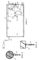
- Fig. 1 is a front view of an emergency lighting unit with the front cover and lamp removed and comprising a receiver in accordance with an embodiment of the present invention;
- Figs. 2 and 3 each illustrate two of several different types of lamps that can be mounted on the emergency lighting unit of Fig. 1;
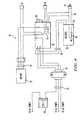
- Fig. 4 is a schematic diagram of an emergency lighting unit connected to a receiver in accordance with an embodiment of the present invention;
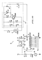
- Fig. 5 is a schematic diagram of a charger board in a emergency lighting unit constructed in accordance with an embodiment of the present invention;
- Figs. 6 and 7 are front and side views, respectively, of a remote transmitter constructed in accordance with an embodiment of the present invention;
- Figs. 8 and 9 are block diagrams of a transmitter and a receiver, respectively, constructed in accordance with an embodiment of the present invention; and
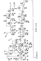
- Figs. 10 and 11 are schematic diagrams of a transmitter and a receiver, respectively, constructed in accordance with an embodiment of the present invention.
- Fig. 1 is a front view of an emergency lighting unit (ELU) 10 having the front cover (not shown) removed to reveal the contents of the
unit housing 12. An incandescent or halogen lamp, such as those depicted at 14 and 14' in Figs. 2 and 3, is mounted in a conventional manner on the top, front or sides of thehousing 12 and thewires 16 are placed through anaperture 18 in thehousing 12 in order to be connected to acharger board 20. With reference to Fig. 4, thehousing 12 encloses abattery 22 which is connected to acharger board 20 viabattery wires 24. Thebattery 22 is an alternate power source when current from an AC power source is not available on theAC line 26, or AC power has been interrupted intentionally to test the ELU, as will be described below. - With continued reference to Fig. 1, the
charger board 20 carries light emitting diodes (LEDs) 28 which extend outside thehousing 12 to indicate that the AC supply is present for the ELU, whether the ELU is in the battery backup mode (i.e., emergency operation mode) and to indicate the status of the battery (i.e., high or low charge). Thehousing 12 allows for mounting of anoptional voltmeter 30 and anammeter 32 that can be connected to thecharger board 20. To test the operation of theELU 10 on battery power, aTEST push button 34 is provided on the housing. When an operator depresses thebutton 34, thecharger board 20 switches thelamp 14 from AC line to battery power. In accordance with an embodiment of the present invention, the ELU 10 can also be tested using areceiver 36, which is mounted in theELU fixture housing 12, in conjunction with a hand-held transmitter depicted in Figs. 6 and 7. - With reference to Fig. 4, the
charger board 20 is connected to a primary power source via atransformer 44 andAC lines 26, to an alternate or auxiliary power source such as abattery 22, to aTEST button 34 and to areceiver 36. Thecharger board 20 can also be connected to anoptional voltmeter 30, anammeter 32 and to atime delay device 40. Thecharger board 20 is preferably a low voltage, low wattage Economy #703069 charger printed circuit board (PCB) manufactured by Hubbell Lighting Incorporated, Christiansburg, Virginia, which switches the lamp output on the negative lead of the battery, as shown in Fig. 5. The ELU 10 is preferably in a model PE612 or HE625 ELU, also manufactured by Hubbell Lighting Incorporated. It is to be understood that other ELUs can be used in accordance with the present invention. Further, other battery and charging assemblies can be used in accordance with the present invention such as the Hubbell low voltage, high wattage, #703067 emergency charger manufactured by Hubbell Lighting Incorporated, which switches the lamp output on the positive lead of the battery. - As shown in Fig. 5, the
charger board 20 is of a conventional type and includes DC rectifying and voltage regulating andtransfer control circuitry 21 for maintaining thebattery 22 in a fully charged condition. Thecharger board 20 has four output terminals designated B+, B-, L+ and L-. The B+ and B- terminals are the battery terminals of the charger board and are connected to the positive and negative terminals of thebattery 22, respectively. The L+ and L- terminals are the lamp output terminals of thecharger board 20 and are connected to thelamp 14 or 14'. The B- terminal is also electrically connected to thelamp 14 or 14' via the PCB 20. - To switch between standby and emergency or test modes, the
charger board 20 comprisestransfer control circuitry 21 and a transfer relay and transistor (indicated generally at 42). Thetransfer control circuitry 21 operates the transfer relay andtransistor 42 to selectively switch the lamp(s) to the battery power source in response to open circuit conditions due to activation of normally closedrelays TEST push button 34 and thereceiver 36, respectively, or the condition of the loss of the primary AC power source. The transfer relay 43 has acoil 45 which is coupled to thetransfer control circuitry 21. When AC power is available, the relay contacts of relay 43 are in an unswitched position to prevent the lamp polarities from being electrically connected to the battery output terminals B+ and B-. This condition allows for the charging andtransfer circuit 21 to maintain the battery in a fully charged condition during the standby mode. When the AC power is interrupted or falls below a predetermined level, thetransfer control circuitry 21 energizes thecoil 45 and allows the relay 43 to go to a switched position. The lamp terminals are therefore electrically connected to the battery terminals. The isolation between the lamp terminals and the battery terminals can also be accomplished using a power transistor. Thus, the relay 43 or a power transistor operates as a transfer switch for automatically initiating emergency or test mode operation in the event of a power supply interruption, and for automatically returning theELU 10 to standby operation once power has been restored. - With continued reference to Fig. 4, the
ELU 10 also comprises atransformer 44 for stepping down the voltage from the primary power source (e.g., a 120 VAC power supply) to a reduced input voltage (e.g., an input voltage range of 10 VAC minimum and 35 VAC maximum). The input voltage is used to power thereceiver 36, as indicated bylines 46, and is used to charge the battery when the ELU is not in an emergency or test mode. - In accordance with an embodiment of the invention, the
TEST button 34 and thereceiver 36 each include a normally closed contact switch and are connected in series with each other, as well as with the power supply inputtransfer control circuitry 21 ofcharger board 20. When either the TEST button 34 (e.g., a momentary push button) or thereceiver 36 is activated and opens its normally closed switch, the supply of input current from the primary power source is interrupted. The transfer control circuitry of thecharger board 20 detects an open circuit condition on theserial line 48 and, accordingly, switches the transfer relay transistor to operate the lamp from the battery. - The
receiver 36 is activated by a transmitted radio frequency (RF) signal generated by the hand-heldtransmitter 50 depicted in Figs. 6 and 7. The transmitter preferably comprises a plastic-moldedhousing 52 having a belt clip 54 and akey ring 56. Thetransmitter housing 52 encloses a battery and a transmitter control circuit as described below in connection with Figs. 8 and 10. A momentarypush button switch 58 is provided such that when it is activated by a user, the transmitter generates a RF control signal via an antenna 60 (Fig. 8) for transmission to thereceiver 36 for essentially as long as the user activates theswitch 58. AnLED 62 or other indicator is provided to indicate when thetransmitter 50 is generating and transmitting a control signal to thereceiver 36. - With reference to Fig. 8, the
transmitter 50 comprises anencoder 64 for generating an encoded signal for as long as thebutton 58 is depressed by a user. Theencoder 64 is connected to a RFsignal generating circuit 66 for combining the encoded signal with a RF carrier signal. The encoded RF signal is amplified by anamplifier 68 and broadcast to the lamp control circuit via theantenna 60. The RFsignal generating circuit 66,amplifier 68, andantenna 60 can be anLC oscillator 92 as described in connection with Fig. 10. It is to be understood that other wireless for communicating with the lamp control unit can be used. For example, the transmitter can be provided with circuitry for modulating the encoded output signal from the encoder into an infrared signal or ultrasonic signal. The receiver in the lamp control unit can be provided with corresponding circuitry for receiving encoded infrared or ultrasonic signals. - With reference to Fig. 9, the
receiver 36 comprises anantenna 70 for receiving encoded RF signals from thetransmitter 50. The RF signals are processed by anamplifier 72 and then demodulated into digital signals by a RFregenerative detector 74, which is tuned to the transmitter frequency, and digitizingoperational amplifiers 76. The digital signals are decoded by adecoder 78, which opens the normally closedrelay 80 to interrupt the primary power supply if the decoded signals are recognized as valid control signals from thetransmitter 50. Thecharger board 20 in turn energizes the transfer relay andtransistor 42, thus connecting thelamp 14 or 14' to the battery. An advantage of placing thereceiver relay 80 in series with themanual TEST button 34 and of using normally closed contacts on therelay 80 is that theELU 10 remains operational and continues to have a manual test function viaTEST button 34 even if thetransmitter 50 orreceiver 36 malfunction. - The encoding and decoding processes will now be described with reference to Figs. 10 and 11, which are schematic diagrams of the
transmitter 50 andreceiver 36, respectively. As shown in Fig. 10, thetransmitter 50 comprises abattery 82 which supplies a voltage Vcc to theencoder 64 as long as theswitch 58 is closed. Theswitch BT1 58 can be a push button-type switch that must be pressed and held to remain closed. Enablepin 14 on theencoder 64 is tied to ground such that the encoder is enabled as long as it is receiving a supply voltage. Theencoder 64 comprises nine pins (i.e., A1 through A9) and is configured to generate one of three different output signals onpin 15 depending on which the nine pins are tied to Vcc, to ground, or are left floating, respectively. For example, theencoder 64 can be configured to generate two wide pulses for each pin connected to Vcc, one wide pulse and one narrow pulse for each pin connected to ground, and two narrow pulses for each pin left floating to create an encoded output signal of eighteen, serial pulses. A three-position switch orjumper 84 can be used to set each pin to a Vcc, ground or floating state. The switch settings can be varied among several transmitters and, correspondingly, among receivers configured to recognize a particular pattern of eighteen, wide and narrow pulses in a received signal. Varying the switch settings reduces the likelihood of unintended reception of transmitted signals by the wrong ELU or other wireless device (e.g., a security device or automatic door in the vicinity of the ELU 10). - With continued reference to Fig. 10, the resistors 86 and 88 and the
capacitor 90 connected to theencoder 64 are selected to establish a predetermined rate of pulses output onpin 15. When a pulse appears onpin 15, anLC oscillator 92 begins oscillating at a tuned frequency (e.g., 318 MHz) for the duration of the wide or narrow pulse. The tuned frequency is preferably selected from a range of frequencies between 286 and 370 MHz and tuning is performed byvaractor 94. Thus, one of the RF pulses in an encoded signal is generated by theoscillator 92 for transmission to thereceiver 36. When no pulse appears onpin 15 of theencoder 64, thetransistor 96 turns thecoil 98 off until the next wide or narrow pulse appears at thepin 15. After eighteen pulses appear on thepin 15, theencoder 64 generates six synchronization pulses before generating the next sequence of eighteen pulses. TheLED 62 is illuminated each time a RF pulse is transmitted. TheLED 62 becomes dim as battery charge decreases and therefore functions as an indicator to replace thetransmitter battery 82. - With reference to Fig. 11, a conventional power supply is provided within the
receiver 36 for converting the voltage from the secondary of thetransformer 44. Thereceiver 36 comprises anantenna 70 and an amplifier (i.e., transistor 102) for amplifying a received RF pulse in an encoded signal. When a RF pulse is received that is tuned to the same frequency as the RF regenerative detector 74 (i.e., atuner comprising capacitors inductor 108,varactor 110, and transistor 112), theregenerative detector 74 changes the amplitude of its oscillating output signal such that the signal can be converted to a square wave, digital signal by theoperational amplifiers operational amplifier 116 is provided to thedecoder 78. - With continued reference to Fig. 11, the
decoder 78 compares the input digital signal atpin 9 with switch data at pins A1 through A9, which are configured in a manner identical to the transmitter using three-position switches orjumpers 118, as described above. When thedecoder 78 detects two identical encoded signals of eighteen pulses, which are separated by a synchronization signal of six pulses, the decoder generates a high output signal atpin 11. Thepin 11 remains high, as long as valid encoded signals are detected by thedecoder 78. The decoder output signal is provided to therelay 80 viagates transistor 124. A high output signal causes thetransistor 124 to conduct and operate therelay coil 126 to open a normally closed contact. Accordingly, thecharger board 20 switches thelamp 14 or 14' to thebattery 22 to operate theELU 10 in a test mode. When the output signal atpin 11 then goes low, thetransistor 124 turns off, and the relay closes. Thecharger board 20 disconnects thelamp 14 or 14' from thebattery 22. - When valid encoded data is being received, the
relay 80 remains open until encoded pulse signals are no longer detected by thedecoder 78, even if there is a momentary loss of data (e.g., the transmitter user unintentionally breaks contact of switch S1 for an instant). Protection against momentary, unintentional loss of encoded data is provided by thesecond gate 122. Since the output signal from thesecond gate 122 is required at one input of thefirst gate 120,gate 122 establishes a minimum time for providing an output signal from thedecoder 78 to thefirst gate 120 that has not changed state (i.e., changed from high to low, or low to high).Capacitor 128 andresistor 130 are selected to set the predetermined minimum time for providing a signal to the first gate without changing state to a desired value (e.g., two seconds). Conversely, if thebutton 58 on thetransmitter 50 is depressed for only a brief period of time (e.g., one second), the test feature is engaged (i.e., a high decoder output signal is generated to open the relay 80) for the minimum time of two seconds. - The present invention is advantageous because, among other reasons, it does not require two transmitted signals to commence and interrupt, respectively, an
ELU 10 test function. An emergency lighting system is provided, in accordance with an embodiment of the present invention, with areceiver 36 connected to anELU 10 and aportable transmitter 50 operable remotely with respect to the ELU. Thetransmitter 50 is configured to generate and transmit a single encoded signal to thereceiver 36 as long as aswitch 58 on the transmitter is activated by the user. Theswitch 58 can be of the type which must be depressed and held to continue generation of the encoded signal, or of the type which is depressed once to commence encoded signal generation and depressed once more to terminate encoded signal generation. Thereceiver 36 receives and decodes the transmitted signal and opens a normally closedrelay 80 as long as the signals are being received. Thebattery 22 in turn is disconnected from the primary power source and connected to thelamp 14 or 14'. When thetransmitter 50 discontinues generation and transmission of encoded signal to the receiver 36 (i.e., theswitch 58 is no longer activated), the receiver closes the normally closedswitch 80. Thebattery 22 in turn is reconnected to the primary power source for recharging. The emergency lighting control system therefore can remotely control the normally closedswitch 80 and, therefore, the switching of the battery between the primary power source and thelamp 14 or 14' using only one transmitted signal and oneswitch 58 on the transmitter, thereby reducing the complexity of the transmitter and the receiver. Further, the time during which the lamp is operating from an auxiliary power source (e.g., battery 22) can be continuous and variable depending on how a user operates theswitch 58 on thetransmitter 50. The test mode, therefore, is not limited to a predetermined period of time, as in some systems for testing ELUs wherein a momentary RF signal initiates a test function using an auxiliary power source such as a battery to power a lamp for a predetermined period of time before reconnecting the battery to the primary power source. - While certain advantageous embodiments have been chosen to illustrate the invention, it will be understood by those skilled in the art that various changes and modifications can be made herein without departing from the scope of the invention as defined in the appended claims. For example, the charging
board 20,test button 34 andreceiver 36 can be designed such that the lamp is switched from a primary power source to an auxiliary power source such as thebattery 22 when a normally open switch is closed in response to the test button being activated or a transmitter signal is received.
Claims (9)
- An emergency lighting system comprising:a lamp;a primary power source for supplying power to said emergency lighting system;a battery for supplying power to said lamp when said lamp is not connected to said primary power source;a lamp control circuit connected to said lamp, said battery and said primary power source; anda transmitter comprising a control switch and operable remotely from said lamp control circuit to generate and transmit a control signal thereto, the duration of said control signal corresponding to the amount of time said control switch is activated;said lamp control circuit comprising a receiver operable to receive said control signal, said lamp control circuit being operable to switch said battery from said primary power source to said lamp in response to receipt of said control signal, and for switching said battery from said lamp to said primary power source for charging after a period of time has elapsed, said period of time corresponding to the duration of said control signal.
- An emergency lighting system as claimed in Claim 1, wherein said control signal is of a signal type selected from the group consisting of a radio frequency signal, an infrared signal, and an ultrasonic signal, said transmitter and said receiver being configured to generate and receive, respectively, said signal type.
- An emergency lighting system as claimed in Claim 1 or 2, wherein said transmitter is portable.
- An emergency lighting system as claimed in any one of claims 1-3, wherein said lamp control circuit comprises a transfer switch which is activated to switch between first and second states in accordance with said control signal.
- An emergency lighting system as claimed in claim 4, wherein said lamp control circuit is configured to switch said battery from said primary power source to said lamp when said transfer switch is in said first state and to switch said battery from said lamp to said primary power source when said transfer switch is in said second state.
- An emergency lighting system as claimed in any one of claims 1-5, wherein said control switch is a momentary push button switch.
- An emergency lighting system as claimed in any one of claims 1-5, wherein said control switch is configured to be manually activated by an operator.
- An emergency lighting system as claimed in claim 6 or 7, wherein the duration of said control signal corresponds to the amount of time said control switch is activated by said operator, and the duration of said period of time for connecting said battery to said lamp corresponds to said amount of time said control switch is activated by said operator.
- A method for remotely controlling the switching of a battery between a primary power source and a lamp, comprising the steps of:activating a switch on a transmitter remotely located with respect to said lamp for a predetermined period of time or a variable period of time;generating a control signal having a duration corresponding to said period of time using said transmitter;transmitting said control signal from said transmitter to a receiver connected to said lamp;receiving said control signal using said receiver;switching a battery from said primary power source to said lamp upon receipt of said control signal;deactivating said control switch;terminating said generating and said transmitting steps; andswitching said battery from said lamp to said primary power source for charging when said control signal is no longer received.
Applications Claiming Priority (2)
| Application Number | Priority Date | Filing Date | Title |
|---|---|---|---|
| US08/576,558 US5929781A (en) | 1995-12-21 | 1995-12-21 | Radio frequency controlled system for testing emergency lighting units |
| US576558 | 1995-12-21 |
Publications (2)
| Publication Number | Publication Date |
|---|---|
| EP0780821A2 true EP0780821A2 (en) | 1997-06-25 |
| EP0780821A3 EP0780821A3 (en) | 1998-04-08 |
Family
ID=24304929
Family Applications (1)
| Application Number | Title | Priority Date | Filing Date |
|---|---|---|---|
| EP96309237A Withdrawn EP0780821A3 (en) | 1995-12-21 | 1996-12-18 | Radio frequency controlled system for testing emergency lighting units |
Country Status (3)
| Country | Link |
|---|---|
| US (1) | US5929781A (en) |
| EP (1) | EP0780821A3 (en) |
| CA (1) | CA2191688A1 (en) |
Families Citing this family (20)
| Publication number | Priority date | Publication date | Assignee | Title |
|---|---|---|---|---|
| DE10006408A1 (en) * | 2000-02-14 | 2001-08-16 | Zumtobel Staff Gmbh | Lighting system |
| US6353391B1 (en) * | 2000-09-15 | 2002-03-05 | Kenneth N. Shearer | Baby bottle locating system |
| JP2005524371A (en) * | 2002-04-24 | 2005-08-11 | カポン,スティーブン | Distribution board |
| US20040160781A1 (en) * | 2003-02-13 | 2004-08-19 | Edmund Farmer | Method and apparatus for providing an improved light |
| US7336003B2 (en) * | 2005-04-05 | 2008-02-26 | Eaton Corporation | Transfer switch and power system including the same |
| US7218056B1 (en) * | 2006-03-13 | 2007-05-15 | Ronald Paul Harwood | Lighting device with multiple power sources and multiple modes of operation |
| US20080298232A1 (en) * | 2007-05-30 | 2008-12-04 | Silicon Storage Technology, Inc. | Systems and methods for wireless transmission and reception of data including processing and buffering features |
| US20080298242A1 (en) * | 2007-05-30 | 2008-12-04 | Yi Fan | Systems and methods for transmission and reception of data including processing and buffering features |
| US8258705B2 (en) * | 2009-04-29 | 2012-09-04 | Hubbell Incorporated | Scotopically enhanced emergency light and control thereof |
| US9098390B2 (en) * | 2010-11-15 | 2015-08-04 | Lifesafety Power, Inc. | Apparatus and method for a networked power management system with one-click remote battery discharge testing |
| US9965935B2 (en) * | 2011-02-28 | 2018-05-08 | Preston Palmer | Alarm device system with simultaneous AC/DC power source |
| US9966791B2 (en) * | 2011-02-28 | 2018-05-08 | Preston Palmer | Central battery interconnected smoke detector system with single wire AC and DC pass-through relay |
| US10922955B2 (en) * | 2011-02-28 | 2021-02-16 | Vireo Tech, Llc | Battery interconnected smoke detector system |
| US10431055B2 (en) | 2011-02-28 | 2019-10-01 | Vireo Tech, Llc | Battery interconnected alert device system with vibrational alert |
| US9752739B2 (en) | 2011-08-29 | 2017-09-05 | Hubbell Incorporated | Emergency lighting assembly having heat conducting member |
| US9386665B2 (en) | 2013-03-14 | 2016-07-05 | Honeywell International Inc. | System for integrated lighting control, configuration, and metric tracking from multiple locations |
| US9791117B2 (en) * | 2013-04-02 | 2017-10-17 | Thomas & Betts International Llc | Emergency lighting fixture with remote control |
| US10985600B2 (en) * | 2017-07-24 | 2021-04-20 | Magtech Industries Corporation | Emergency lighting system with integrated testing and reporting functionality |
| US10819140B1 (en) * | 2018-07-11 | 2020-10-27 | Maalouf Mark A | Systems and methods for remote monitoring and control of emergency electrical generating systems |
| US11149912B2 (en) * | 2020-02-05 | 2021-10-19 | Litetronics International, Inc. | Emergency high bay light |
Citations (2)
| Publication number | Priority date | Publication date | Assignee | Title |
|---|---|---|---|---|
| US5148158A (en) | 1988-03-24 | 1992-09-15 | Teledyne Industries, Inc. | Emergency lighting unit having remote test capability |
| US5154504A (en) | 1989-08-31 | 1992-10-13 | Minitronics Pty Limited | Communications and testing for emergency systems |
Family Cites Families (8)
| Publication number | Priority date | Publication date | Assignee | Title |
|---|---|---|---|---|
| GB1567506A (en) * | 1978-01-25 | 1980-05-14 | Sunbeam Lamps & Lighting Ltd | Emergency lighting units and installations |
| US4725827A (en) * | 1986-06-23 | 1988-02-16 | Pulsar Manufacturing, Inc. | Hand held remote control device |
| US4908604A (en) * | 1987-09-21 | 1990-03-13 | Dimango Products Corporation | Remotely controlled security system |
| EP0332783B1 (en) * | 1988-03-09 | 1992-06-03 | Pulsar Light Of Cambridge Ltd | Improved spotlight and control system therefor |
| FR2631754B1 (en) * | 1988-05-20 | 1993-07-30 | Accumulateurs Fixes | SELF-LIFE TEST APPARATUS FOR SAFETY LIGHTING BLOCK |
| US4908602A (en) * | 1989-03-31 | 1990-03-13 | Lifeline Systems, Inc. | Apparatus and method of testing a portable held button for emergency response system |
| US4977353A (en) * | 1989-08-31 | 1990-12-11 | Minitronics Pty Limited | Communication system for single point emergency lighting |
| US5365145A (en) * | 1993-08-09 | 1994-11-15 | Gael, Inc. | Emergency lighting system |
-
1995
- 1995-12-21 US US08/576,558 patent/US5929781A/en not_active Expired - Fee Related
-
1996
- 1996-11-29 CA CA002191688A patent/CA2191688A1/en not_active Abandoned
- 1996-12-18 EP EP96309237A patent/EP0780821A3/en not_active Withdrawn
Patent Citations (2)
| Publication number | Priority date | Publication date | Assignee | Title |
|---|---|---|---|---|
| US5148158A (en) | 1988-03-24 | 1992-09-15 | Teledyne Industries, Inc. | Emergency lighting unit having remote test capability |
| US5154504A (en) | 1989-08-31 | 1992-10-13 | Minitronics Pty Limited | Communications and testing for emergency systems |
Also Published As
| Publication number | Publication date |
|---|---|
| EP0780821A3 (en) | 1998-04-08 |
| CA2191688A1 (en) | 1997-06-22 |
| US5929781A (en) | 1999-07-27 |
Similar Documents
| Publication | Publication Date | Title |
|---|---|---|
| US5929781A (en) | Radio frequency controlled system for testing emergency lighting units | |
| US4355309A (en) | Radio frequency controlled light system | |
| US7486883B2 (en) | Radio remote control for photographic equipment | |
| KR900009143B1 (en) | Cordless telephone system | |
| US6759966B1 (en) | Wireless remote control bulb device | |
| US6414589B1 (en) | Apparatus for remotely controlling auxiliary doorbell chime from doorbell push button | |
| US20020009296A1 (en) | Transceiver units and a transceiver system for the remote control of electronic equipment | |
| US4780910A (en) | Display for a remote receiver in an electrical utility load management system | |
| US6630800B2 (en) | Remote-control device of lamp series control box | |
| US20110012434A1 (en) | Power system with light-controlled function and the control method thereof | |
| GB2308910A (en) | Lighting control | |
| CA2021066C (en) | Apparatus for controlling a power supply of an electric machine in a vehicle | |
| GB2287337A (en) | Vehicle control system | |
| WO1997029560A8 (en) | Remotely controlling and determining electrical device status | |
| US6256479B1 (en) | Wireless door intercom | |
| GB2230163A (en) | Controlling home appliances by audio tones transmitted over a telephone line or generated locally | |
| GB2259172A (en) | Wireless remote control transmitter and receiver for electrical appliances | |
| EP1501059A1 (en) | Remote doorbell chime extender | |
| US20040100151A1 (en) | Wireless in-line low-voltage controller | |
| GB2068614A (en) | Remote mains switching means | |
| EP3266088A1 (en) | Outlet control system | |
| JPH06105374A (en) | Electric device controller | |
| KR200251373Y1 (en) | A streetlight remote watching system | |
| KR100427950B1 (en) | A streetlight remote watching system | |
| JPH1092586A (en) | Luminaire provided with remote control function |
Legal Events
| Date | Code | Title | Description |
|---|---|---|---|
| PUAI | Public reference made under article 153(3) epc to a published international application that has entered the european phase |
Free format text: ORIGINAL CODE: 0009012 |
|
| AK | Designated contracting states |
Kind code of ref document: A2 Designated state(s): DE GB NL |
|
| PUAL | Search report despatched |
Free format text: ORIGINAL CODE: 0009013 |
|
| AK | Designated contracting states |
Kind code of ref document: A3 Designated state(s): DE GB NL |
|
| 17P | Request for examination filed |
Effective date: 19980929 |
|
| 17Q | First examination report despatched |
Effective date: 20020212 |
|
| GRAH | Despatch of communication of intention to grant a patent |
Free format text: ORIGINAL CODE: EPIDOS IGRA |
|
| STAA | Information on the status of an ep patent application or granted ep patent |
Free format text: STATUS: THE APPLICATION IS DEEMED TO BE WITHDRAWN |
|
| 18D | Application deemed to be withdrawn |
Effective date: 20030104 |