EP0780268A1 - Fixing system for a car liner - Google Patents
Fixing system for a car liner Download PDFInfo
- Publication number
- EP0780268A1 EP0780268A1 EP96402720A EP96402720A EP0780268A1 EP 0780268 A1 EP0780268 A1 EP 0780268A1 EP 96402720 A EP96402720 A EP 96402720A EP 96402720 A EP96402720 A EP 96402720A EP 0780268 A1 EP0780268 A1 EP 0780268A1
- Authority
- EP
- European Patent Office
- Prior art keywords
- parts
- tab
- internal
- support
- external wall
- Prior art date
- Legal status (The legal status is an assumption and is not a legal conclusion. Google has not performed a legal analysis and makes no representation as to the accuracy of the status listed.)
- Granted
Links
- 239000000463 material Substances 0.000 claims abstract description 5
- 239000012815 thermoplastic material Substances 0.000 claims abstract description 5
- 239000011324 bead Substances 0.000 claims description 7
- 230000000903 blocking effect Effects 0.000 claims description 6
- 239000002184 metal Substances 0.000 description 2
- 239000011248 coating agent Substances 0.000 description 1
- 238000000576 coating method Methods 0.000 description 1
- 230000014759 maintenance of location Effects 0.000 description 1
- 238000000034 method Methods 0.000 description 1
- 238000000465 moulding Methods 0.000 description 1
- 229920001169 thermoplastic Polymers 0.000 description 1
- 239000004416 thermosoftening plastic Substances 0.000 description 1
Images


Classifications
-
- F—MECHANICAL ENGINEERING; LIGHTING; HEATING; WEAPONS; BLASTING
- F16—ENGINEERING ELEMENTS AND UNITS; GENERAL MEASURES FOR PRODUCING AND MAINTAINING EFFECTIVE FUNCTIONING OF MACHINES OR INSTALLATIONS; THERMAL INSULATION IN GENERAL
- F16B—DEVICES FOR FASTENING OR SECURING CONSTRUCTIONAL ELEMENTS OR MACHINE PARTS TOGETHER, e.g. NAILS, BOLTS, CIRCLIPS, CLAMPS, CLIPS OR WEDGES; JOINTS OR JOINTING
- F16B5/00—Joining sheets or plates, e.g. panels, to one another or to strips or bars parallel to them
- F16B5/12—Fastening strips or bars to sheets or plates, e.g. rubber strips, decorative strips for motor vehicles, by means of clips
- F16B5/123—Auxiliary fasteners specially designed for this purpose
- F16B5/125—Auxiliary fasteners specially designed for this purpose one of the auxiliary fasteners is comprising wire or sheet material or is made thereof
-
- B—PERFORMING OPERATIONS; TRANSPORTING
- B60—VEHICLES IN GENERAL
- B60R—VEHICLES, VEHICLE FITTINGS, OR VEHICLE PARTS, NOT OTHERWISE PROVIDED FOR
- B60R13/00—Elements for body-finishing, identifying, or decorating; Arrangements or adaptations for advertising purposes
- B60R13/02—Internal Trim mouldings ; Internal Ledges; Wall liners for passenger compartments; Roof liners
- B60R13/0206—Arrangements of fasteners and clips specially adapted for attaching inner vehicle liners or mouldings
-
- F—MECHANICAL ENGINEERING; LIGHTING; HEATING; WEAPONS; BLASTING
- F16—ENGINEERING ELEMENTS AND UNITS; GENERAL MEASURES FOR PRODUCING AND MAINTAINING EFFECTIVE FUNCTIONING OF MACHINES OR INSTALLATIONS; THERMAL INSULATION IN GENERAL
- F16B—DEVICES FOR FASTENING OR SECURING CONSTRUCTIONAL ELEMENTS OR MACHINE PARTS TOGETHER, e.g. NAILS, BOLTS, CIRCLIPS, CLAMPS, CLIPS OR WEDGES; JOINTS OR JOINTING
- F16B5/00—Joining sheets or plates, e.g. panels, to one another or to strips or bars parallel to them
- F16B5/12—Fastening strips or bars to sheets or plates, e.g. rubber strips, decorative strips for motor vehicles, by means of clips
- F16B5/126—Fastening strips or bars to sheets or plates, e.g. rubber strips, decorative strips for motor vehicles, by means of clips at least one of the sheets, plates, bars or strips having integrally formed or integrally connected snap-in-features
Definitions
- the present invention relates to a system for fixing on a support of an assembly comprising two parts, in particular of the trim of a motor vehicle, such as the trim of the center leg thereof.
- this known system has the drawback of using added elements, such as screws, staples, pins, to hold and connect the two parts as well as to fix them to one face of the middle leg forming sheet metal support.
- the object of the present invention is to eliminate the above drawback by proposing a fastening system which does not require any added elements, or fastening tools for assembling the two parts together and fixing them to their corresponding support, and simplifying the assembly of the two parts.
- the system for attaching to a support an assembly comprising two parts assembled together leaving only a junction line visible on the outside and fixed to the support respectively at their two ends opposite the line. junction by fixing means, such as screws, is characterized in that it comprises means for stapling the first part to the support and means for fastening the second part to the first part.
- the means for stapling the first part to the support comprise two internal tabs integral with the first part and arranged to fit respectively into two slots in the support.
- Each aforementioned internal tab comprises at least one rib removably retaining the tab in the corresponding slot in the support.
- the two abovementioned internal legs are each approximately in the form of an elongated V extending substantially parallel to the longitudinal axis of the first part with the opening of the V of each internal leg directed towards the external wall of the first part, the two internal tabs being connected to the end part of the first part opposite to that fixed to the support via respectively two slightly flexible connection parts holding the edges of the V openings of the two internal legs substantially in the same internal plane parallel to the external wall of the first part.
- Each retaining rib of the corresponding internal tab is integral with a side of the V of the tab, extending practically over the entire length thereof.
- the means for fastening the second part to the first part comprise two rigid internal tabs integral with the end part of the second part, extending substantially perpendicularly to the external wall thereof and being able to force to commit respectively in the two V openings of the two internal tabs of the first part.
- Each rigid tab of the second part comprises, integral with each side thereof, at least one lateral rib perpendicular to the plane of the tab and defining a triangle whose apex is located in the vicinity of the free end of the tab and the base is secured to the outer wall of the second part.
- the system of the invention further comprises means for mutual locking of the two parts.
- these mutual blocking means comprise a tab integral with the second part in the vicinity of the end part thereof and coming to be applied on the internal face of the external wall of the first part during assembly. of these two parts so as to block the second part relative to the first part when the second part is fixed to the support; and two parallel recess parts extending the end of the first part, overlapped respectively by two recessed or hollow parts of conjugate shape from the end of the second part in the assembled position thereof so as to block the first part relative to the second room.
- the recess of the two aforementioned parts of the first part is such that it ensures the continuity of the two external walls respectively of the two parts assembled together.
- the system of the invention also includes indexing means allowing correct relative positioning of the two parts.
- the indexing means comprise hooks of one of the two parts cooperating with a bead or rim of the other part.
- the above-mentioned hooks are produced on the blocking tab of the second part and the bead is produced on the internal face of the external wall of the first part transversely to the latter.
- the external wall of the second part comprises a depression allowing the passage of a seat belt between the second part and the first part and delimited by two flanges respectively defining the two abovementioned recessed portions overlapping the two recessed portions.
- the locking tab of the second part is an extension of the aforementioned depression.
- the two parts are made of a thermoplastic material or covered with such a material.
- references 1 and 2 respectively designate two elongated parts, partially shown, of a lining of the middle foot of a motor vehicle in a thermoplastic material or other material on which a thermoplastic coating will be suitably attached.
- the part 1 constitutes the lower part of the center leg trim while the part 2 constitutes the upper part thereof.
- Parts 1 and 2 can be assembled together leaving only a junction line 3 visible on the outside and are fixed to a sheet metal support 4, constituting a face of the middle leg (not shown), respectively at their two ends (not shown) opposite the junction line 3 by fixing means, such as screws.
- the fixing system of the invention making it possible to assemble the two parts 1, 2 together and to fix these two assembled parts to the support 4 comprises stapling means 5 of the lower part 1 on the support 4 and means d stapling 6 of the upper part 2 to the lower part 1.
- the stapling means 5 of the lower part 1 on the support 4 comprise two internal tabs 7 integral with the lower part 1 and arranged to fit respectively in two slots 8 of the support 4 in a removable manner.
- the two internal tabs 7 are each approximately in the form of an elongated V extending substantially parallel to the longitudinal axis of the lower part 1, which comprises an external wall 1a provided with lateral flanges 1b substantially perpendicular to the wall 1a. .
- the two internal stapling tabs 7 are connected to the end of the lower part 1 opposite to that fixed to the support 4 via respectively two slightly flexible connection parts 9 each of which is connected to a gutter-shaped part inverted 10 extending the corresponding end part of the lower part 1 by defining with respect thereto a recess 11.
- the connecting parts 9, 10 hold the edges of the openings of the Vs of the two stapling tabs 7 substantially in a same internal plane spaced from the wall la and substantially parallel to the latter with the opening of the V of each tab 7 directed towards the wall la.
- each stapling tab 7 comprises two ribs 7b intended to removably retain the tab 7 in the corresponding slot 8 of the support 4.
- Each retaining rib 7b is integral with a side 7c of the V of the tab 7 extending practically over the entire length thereof.
- Each rib 7b has in cross section the shape of a triangle, the top of which is connected to the free end of the stapling tab 7 and the base constitutes a retaining shoulder for the tab 7 which comes to bear behind the support 4.
- the stapling means 6 of the upper part 2 on the lower part 1 comprise two rigid internal tabs 12 integral with the end part of the upper part 2 extending substantially perpendicularly to the external wall 2a thereof and by being arranged substantially parallel to the longitudinal axis of the part 2, which comprises two lateral flanges 2b substantially perpendicular to the wall 2a.
- the two stapling tabs 12 can forcely engage respectively in the two openings 7a of the Vs of the two stapling tabs 7 of the lower part 1 during the assembly of these two parts.
- Each staple tab 12 comprises, integral with each side thereof, two lateral ribs 12a perpendicular to the plane of the tab 12 and defining a triangle the apex of which is in the vicinity of the free end of the tab 12 and the base is integral with the internal face of the external wall 2a of the part 2.
- the ribs 12a make it possible to improve the retention by force of the legs 12 in the corresponding openings of the V of the legs d stapling 7.
- the fixing system according to the invention further comprises means for mutual locking of the two parts 1 and 2.
- These mutual blocking means comprise a tab 13 secured to the end of the upper part 2 by extending the latter and which can come into application on the internal face of the wall 1a of the part 1 during the assembly of these two parts. 1, 2 so as to prevent movement of the upper part 2 relative to the lower part 1 in the direction indicated by the arrow F1 in FIG. 2 when, of course, the parts 1, 2 are fixed to the support 4 at their respective ends opposite to the junction line 3.
- the mutual blocking means also comprise the two parts in the form of an inverted gutter 10 of the part 1 which overlap respectively two recessed or hollow parts of conjugate form 2c each defined between a flange 2b and the tab of blocking 13 so that in the assembled position of the parts 1, 2, the lower part 1 cannot move relative to the upper part 2 in the direction indicated p ar arrow F2 in figure 2.
- step 11 of the lower part 1 is such that it ensures the continuity of the two external walls la, 2a respectively of the two parts assembled together 1, 2 as shown in FIG. 2.
- the fastening system also includes indexing means allowing correct relative positioning of the two parts 1, 2, that is to say ensuring good contact and a practically zero, and in any case constant, clearance between these two parts.
- indexing means comprise two hooks 14 preferably produced on the locking tab 13 of the part 2 on each side of the latter and a bead or flange 15 preferably produced on the internal face of the wall 1a of the external part 1 transversely to the latter.
- the wall 2a of the part 2 comprises a hollow or depression part 16 delimited by two flanges 2d which themselves define the two hollow parts 2c respectively overlapping the two gutter-shaped parts reversed 10 of the part 1.
- This depression 16 allows the passage of a seat belt between the upper part 2 and the lower part 1.
- the locking tab 13 is located in extension of the bottom of the depression 16.
- FIG. 7 represents an alternative embodiment of the locking tab 13 which, in the present case, defines with respect to the internal face of the wall 2a of the upper part 2 a transverse opening in which the part of corresponding end 1c of the part 1.
- This figure shows that the end part 1c defines the step 11 relative to the wall la so as to ensure continuity between the walls la and 2a of the parts 1, 2.
- the lower part 1 is fixed to the support 4 by introducing the two legs 7 into their respective slots 8 of the support 4 until the ribs 7b are behind the support 4 so as to retain the legs 7, therefore part 1, on support 4.
- the upper part 2 is assembled to the lower part 1 by introducing the locking tab 13 into the space E defined between the end of the wall la and the stapling tabs 7 so that on the one hand the tabs of stapling 12 of the part 2 engage by force in the openings 7a of the V of the legs 7 and on the other hand the two hooks 14 engage on the bead 15 of the part 1 with overlapping concomitant parts in the form of inverted gutter 10 by the hollow parts 2c of the part 2.
- the parts 1 and 2 are then fixed, at their ends opposite to the junction line 3, to the support 4 by suitable fixing means.
- the assembly thus produced is such that the lower part 1 is locked in position and can no longer be disassembled without the upper part 2 being so beforehand.
- the upper part 2 is also locked in position by the locking tab 13.
- Each part 1, 2 is preferably produced by molding.
Landscapes
- Engineering & Computer Science (AREA)
- General Engineering & Computer Science (AREA)
- Mechanical Engineering (AREA)
- Connection Of Plates (AREA)
- Motor Power Transmission Devices (AREA)
Abstract
Description
La présente invention concerne un système de fixation sur un support d'un ensemble comprenant deux pièces, en particulier de garniture de véhicule automobile, telle que la garniture de pied milieu de celui-ci.The present invention relates to a system for fixing on a support of an assembly comprising two parts, in particular of the trim of a motor vehicle, such as the trim of the center leg thereof.
On connaît un tel système selon lequel les deux pièces de la garniture de pied milieu du véhicule, en un matériau thermoplastique ou recouvertes d'un tel matériau, sont assemblées entre elles en ne laissant apparaître extérieurement qu'une ligne de jonction et sont fixées à un support respectivement à leurs deux extrémités opposées à la ligne de jonction par des éléments de fixation tels que des vis.There is a known such system according to which the two parts of the foot pad in the middle of the vehicle, made of a thermoplastic material or covered with such a material, are assembled together leaving only a junction line visible on the outside and are fixed to a support respectively at their two ends opposite the junction line by fastening elements such as screws.
Cependant, ce système connu a pour inconvénient d'utiliser des éléments rapportés, tels que des vis, des agrafes, des pions, pour effectuer la tenue et la liaison des deux pièces ainsi que pour fixer celles-ci à une face du pied milieu formant support en tôle.However, this known system has the drawback of using added elements, such as screws, staples, pins, to hold and connect the two parts as well as to fix them to one face of the middle leg forming sheet metal support.
La présente invention a pour but d'éliminer l'inconvénient ci-dessus en proposant un système de fixation ne nécessitant pas d'éléments rapportés, ni d'outillage de fixation pour assembler entre elles les deux pièces et les fixer à leur support correspondant, et simplifiant l'assemblage des deux pièces.The object of the present invention is to eliminate the above drawback by proposing a fastening system which does not require any added elements, or fastening tools for assembling the two parts together and fixing them to their corresponding support, and simplifying the assembly of the two parts.
A cet effet, selon l'invention, le système de fixation sur un support d'un ensemble comprenant deux pièces assemblées entre elles en ne laissant apparaître extérieurement qu'une ligne de jonction et fixées au support respectivement à leurs deux extrémités opposées à la ligne de jonction par des moyens de fixation, tels que des vis, est caractérisé en ce qu'il comprend des moyens d'agrafage de la première pièce sur le support et des moyens d'agrafage de la deuxième pièce sur la première pièce.To this end, according to the invention, the system for attaching to a support an assembly comprising two parts assembled together leaving only a junction line visible on the outside and fixed to the support respectively at their two ends opposite the line. junction by fixing means, such as screws, is characterized in that it comprises means for stapling the first part to the support and means for fastening the second part to the first part.
De préférence, les moyens d'agrafage de la première pièce sur le support comprennent deux pattes internes solidaires de la première pièce et agencées pour s'encastrer respectivement dans deux fentes du support.Preferably, the means for stapling the first part to the support comprise two internal tabs integral with the first part and arranged to fit respectively into two slots in the support.
Chaque patte interne précitée comprend au moins une nervure retenant amoviblement la patte dans la fente correspondante du support.Each aforementioned internal tab comprises at least one rib removably retaining the tab in the corresponding slot in the support.
Avantageusement, les deux pattes internes précitées sont chacune approximativement en forme de V allongé s'étendant sensiblement parallèlement à l'axe longitudinal de la première pièce avec l'ouverture du V de chaque patte interne dirigée vers la paroi externe de la première pièce, les deux pattes internes étant raccordées à la partie d'extrémité de la première pièce opposée à celle fixée au support par l'intermédiaire respectivement de deux parties légèrement flexibles de raccordement maintenant les bords des ouvertures des V des deux pattes internes sensiblement dans un même plan interne parallèle à la paroi externe de la première pièce.Advantageously, the two abovementioned internal legs are each approximately in the form of an elongated V extending substantially parallel to the longitudinal axis of the first part with the opening of the V of each internal leg directed towards the external wall of the first part, the two internal tabs being connected to the end part of the first part opposite to that fixed to the support via respectively two slightly flexible connection parts holding the edges of the V openings of the two internal legs substantially in the same internal plane parallel to the external wall of the first part.
Chaque nervure de retenue de la patte interne correspondante est solidaire d'un flanc du V de la patte en s'étendant pratiquement sur toute la longueur de celui-ci.Each retaining rib of the corresponding internal tab is integral with a side of the V of the tab, extending practically over the entire length thereof.
De préférence, les moyens d'agrafage de la seconde pièce sur la première pièce comprennent deux pattes internes rigides solidaires de la partie d'extrémité de la seconde pièce en s'étendant sensiblement perpendiculairement à la paroi externe de celle-ci et pouvant s'engager à force respectivement dans les deux ouvertures des V des deux pattes internes de la première pièce.Preferably, the means for fastening the second part to the first part comprise two rigid internal tabs integral with the end part of the second part, extending substantially perpendicularly to the external wall thereof and being able to force to commit respectively in the two V openings of the two internal tabs of the first part.
Chaque patte rigide de la seconde pièce comprend, solidaire de chaque côté de celle-ci, au moins une nervure latérale perpendiculaire au plan de la patte et définissant un triangle dont le sommet se trouve au voisinage de l'extrémité libre de la patte et la base est solidaire de la paroi externe de la seconde pièce.Each rigid tab of the second part comprises, integral with each side thereof, at least one lateral rib perpendicular to the plane of the tab and defining a triangle whose apex is located in the vicinity of the free end of the tab and the base is secured to the outer wall of the second part.
Le système de l'invention comprend en outre des moyens de blocage mutuel des deux pièces.The system of the invention further comprises means for mutual locking of the two parts.
De préférence, ces moyens de blocage mutuel comprennent une patte solidaire de la seconde pièce au voisinage de la partie d'extrémité de celle-ci et venant s'appliquer sur la face interne de la paroi externe de la première pièce lors de l'assemblage de ces deux pièces de façon à bloquer la seconde pièce relativement à la première pièce lorsque la seconde pièce est fixée au support; et deux parties de décrochement parallèles prolongeant l'extrémité de la première pièce, que viennent chevaucher respectivement deux parties évidées ou en creux de forme conjuguée de l'extrémité de la seconde pièce en position assemblée de celle-ci de façon à bloquer la première pièce relativement à la deuxième pièce.Preferably, these mutual blocking means comprise a tab integral with the second part in the vicinity of the end part thereof and coming to be applied on the internal face of the external wall of the first part during assembly. of these two parts so as to block the second part relative to the first part when the second part is fixed to the support; and two parallel recess parts extending the end of the first part, overlapped respectively by two recessed or hollow parts of conjugate shape from the end of the second part in the assembled position thereof so as to block the first part relative to the second room.
Le décrochement des deux parties précitées de la première pièce est tel qu'il assure la continuité des deux parois externes respectivement des deux pièces assemblées entre elles.The recess of the two aforementioned parts of the first part is such that it ensures the continuity of the two external walls respectively of the two parts assembled together.
Le système de l'invention comprend également des moyens d'indexage permettant un positionnement relatif correct des deux pièces.The system of the invention also includes indexing means allowing correct relative positioning of the two parts.
A cet effet, les moyens d'indexage comprennent des crochets de l'une des deux pièces coopérant avec un bourrelet ou rebord de l'autre pièce.To this end, the indexing means comprise hooks of one of the two parts cooperating with a bead or rim of the other part.
Avantageusement, les crochets précités sont réalisés sur la patte de blocage de la seconde pièce et le bourrelet est réalisé sur la face interne de la paroi externe de la première pièce transversalement à cette dernière.Advantageously, the above-mentioned hooks are produced on the blocking tab of the second part and the bead is produced on the internal face of the external wall of the first part transversely to the latter.
Dans l'application des deux pièces à une garniture de véhicule automobile, notamment de pied milieu de celui-ci, la paroi externe de la seconde pièce comprend une dépression permettant le passage d'une ceinture de sécurité entre la seconde pièce et la première pièce et délimitée par deux rebords définissant respectivement les deux parties en creux précitées chevauchant les deux parties de décrochement.In the application of the two parts to a trim of a motor vehicle, in particular of the center leg thereof, the external wall of the second part comprises a depression allowing the passage of a seat belt between the second part and the first part and delimited by two flanges respectively defining the two abovementioned recessed portions overlapping the two recessed portions.
Avantageusement, la patte de blocage de la seconde pièce est en prolongement de la dépression précitée.Advantageously, the locking tab of the second part is an extension of the aforementioned depression.
Les deux pièces sont en un matériau thermoplastique ou recouvertes d'un tel matériau.The two parts are made of a thermoplastic material or covered with such a material.
L'invention sera mieux comprise et d'autres buts, caractéristiques, détails et avantages de celle-ci apparaîtront plus clairement au cours de la description explicative qui va suivre faite en référence aux dessins schématiques annexés donnés uniquement à titre d'exemple illustrant deux modes de réalisation de l'invention et dans lesquels :
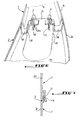
- La figure 1 est une vue en perspective représentant les deux parties d'extrémité respectivement de deux pièces de garniture de pied milieu de véhicule automobile en position avant assemblage ;
- La figure 2 est une vue en perspective représentant les deux pièces de la figure 1 en position assemblée ;
- La figure 3 est une vue en coupe suivant la ligne III-III de la figure 2 ;
- La figure 4 est une vue en section suivant la ligne IV-IV de la figure 1 et représentant la fixation de l'une des deux pièces de garniture à un support correspondant ;
- La figure 5 est une vue en coupe suivant la ligne V-V de la figure 2 et représentant les deux pièces assemblées fixées au support correspondant ;
- La figure 6 est une vue en perspective de dessous des deux pièces assemblées de la figure 2.
- La figure 7 représente en coupe un autre mode de réalisation de moyens de blocage mutuel des deux pièces.
- Figure 1 is a perspective view showing the two end portions respectively of two parts of the foot trim of the middle of the motor vehicle in position before assembly;
- Figure 2 is a perspective view showing the two parts of Figure 1 in the assembled position;
- Figure 3 is a sectional view along line III-III of Figure 2;
- Figure 4 is a sectional view along line IV-IV of Figure 1 and showing the attachment of one of the two trim pieces to a corresponding support;
- Figure 5 is a sectional view along line VV of Figure 2 and showing the two assembled parts attached to the corresponding support;
- FIG. 6 is a perspective view from below of the two assembled parts of FIG. 2.
- Figure 7 shows in section another embodiment of mutual locking means of the two parts.
En se reportant aux figures, les références 1 et 2 désignent respectivement deux pièces allongées, représentées partiellement, d'une garniture de pied milieu de véhicule automobile en un matériau thermoplastique ou autre matériau sur lequel sera rapporté de façon appropriée un revêtement thermoplastique.Referring to the figures, the
La pièce 1 constitue la partie inférieure de la garniture de pied milieu tandis que la pièce 2 constitue la partie supérieure de celle-ci.The part 1 constitutes the lower part of the center leg trim while the
Les pièces 1 et 2 peuvent être assemblées entre elles en ne laissant apparaître extérieurement qu'une ligne de jonction 3 et sont fixées à un support en tôle 4, constituant une face du pied milieu (non représenté), respectivement à leurs deux extrémités (non représentées) opposées à la ligne de jonction 3 par des moyens de fixation, tels que des vis.
Le système de fixation de l'invention permettant d'assembler entre elles les deux pièces 1, 2 et de fixer ces deux pièces assemblées au support 4 comprend des moyens d'agrafage 5 de la pièce inférieure 1 sur le support 4 et des moyens d'agrafage 6 de la pièce supérieure 2 sur la pièce inférieure 1.The fixing system of the invention making it possible to assemble the two
De préférence, les moyens d'agrafage 5 de la pièce inférieure 1 sur le support 4 comprennent deux pattes internes 7 solidaires de la pièce inférieure 1 et agencées pour s'encastrer respectivement dans deux fentes 8 du support 4 de façon amovible.Preferably, the stapling means 5 of the lower part 1 on the support 4 comprise two
A cet effet, les deux pattes internes 7 sont chacune approximativement en forme de V allongé s'étendant sensiblement parallèlement à l'axe longitudinal de la pièce inférieure 1, qui comprend une paroi externe la pourvue de rebords latéraux 1b sensiblement perpendiculaires à la paroi la. Les deux pattes internes d'agrafage 7 sont raccordées à l'extrémité de la pièce inférieure 1 opposée à celle fixée au support 4 par l'intermédiaire respectivement de deux parties de raccordement 9 légèrement flexibles dont chacune est raccordée à une partie en forme de gouttière inversée 10 prolongeant la partie d'extrémité correspondante de la pièce inférieure 1 en définissant par rapport à celle-ci un décrochement 11. Les parties de raccordement 9, 10 maintiennent les bords des ouvertures des V des deux pattes d'agrafage 7 sensiblement dans un même plan interne espacé de la paroi la et sensiblement parallèle à cette dernière avec l'ouverture du V de chaque patte 7 dirigée vers la paroi la.For this purpose, the two
Comme cela est clairement représenté aux figures 4 et 5, chaque patte d'agrafage 7 comprend deux nervures 7b destinées à retenir amoviblement la patte 7 dans la fente correspondante 8 du support 4. Chaque nervure de retenue 7b est solidaire d'un flanc 7c du V de la patte 7 en s'étendant pratiquement sur toute la longueur de celui-ci. Chaque nervure 7b présente en section transversale la forme d'un triangle dont le sommet est raccordé à l'extrémité libre de la patte d'agrafage 7 et la base constitue un épaulement de retenue de la patte 7 venant en appui derrière le support 4. Bien entendu, il est possible de ne prévoir qu'une seule nervure 7b à chaque patte d'agrafage 7.As is clearly shown in Figures 4 and 5, each
Les moyens d'agrafage 6 de la pièce supérieure 2 sur la pièce inférieure 1 comprennent deux pattes internes rigides 12 solidaires de la partie d'extrémité de la pièce supérieure 2 en s'étendant sensiblement perpendiculairement à la paroi externe 2a de celle-ci et en étant disposées sensiblement parallèlement à l'axe longitudinal de la pièce 2, laquelle comporte deux rebords latéraux 2b sensiblement perpendiculaires à la paroi 2a.The stapling means 6 of the
Les deux pattes d'agrafage 12 peuvent s'engager à force respectivement dans les deux ouvertures 7a des V des deux pattes d'agrafage 7 de la pièce inférieure 1 lors de l'assemblage de ces deux pièces.The two
Chaque patte d'agrafage 12 comprend, solidaires de chaque côté de celle-ci, deux nervures latérales 12a perpendiculaires au plan de la patte 12 et définissant un triangle dont le sommet se trouve au voisinage de l'extrémité libre de la patte 12 et la base est solidaire de la face interne de la paroi externe 2a de la pièce 2. Les nervures 12a permettent d'améliorer le maintien à force des pattes 12 dans les ouvertures correspondantes des V des pattes d'agrafage 7.Each
Le système de fixation conforme à l'invention comprend en outre des moyens de blocage mutuel des deux pièces 1 et 2.The fixing system according to the invention further comprises means for mutual locking of the two
Ces moyens de blocage mutuel comprennent une patte 13 solidaire de l'extrémité de la pièce supérieure 2 en prolongeant celle-ci et pouvant venir en application sur la face interne de la paroi la de la pièce 1 lors de l'assemblage de ces deux pièces 1, 2 de façon à empêcher un déplacement de la pièce supérieure 2 relativement à la pièce inférieure 1 suivant le sens indiqué par la flèche F1 en figure 2 lorsque bien entendu les pièces 1, 2 sont fixées au support 4 à leurs extrémités respectives opposées à la ligne de jonction 3. Les moyens de blocage mutuel comprennent également les deux parties en forme de gouttière inversée 10 de la pièce 1 que viennent chevaucher respectivement deux parties évidées ou en creux de forme conjuguée 2c définies chacune entre un rebord 2b et la patte de blocage 13 de façon qu'en position assemblée des pièces 1, 2, la pièce inférieure 1 ne puisse se déplacer relativement à la pièce supérieure 2 dans le sens indiqué par la flèche F2 en figure 2.These mutual blocking means comprise a
On notera que le décrochement 11 de la pièce inférieure 1 est tel qu'il assure la continuité des deux parois externes la, 2a respectivement des deux pièces assemblées entre elles 1, 2 comme cela ressort de la figure 2.It will be noted that the
Le système de fixation comprend également des moyens d'indexage permettant un positionnement relatif correct des deux pièces 1, 2, c'est-à-dire assurant un bon contact et un jeu pratiquement nul, et en tout cas constant, entre ces deux pièces.The fastening system also includes indexing means allowing correct relative positioning of the two
Ces moyens d'indexage comprennent deux crochets 14 de préférence réalisés sur la patte de blocage 13 de la pièce 2 de chaque côté de celle-ci et un bourrelet ou rebord 15 de préférence réalisé sur la face interne de la paroi la de la pièce extérieure 1 transversalement à cette dernière. Ainsi, en position assemblée des deux pièces 1, 2, les deux crochets 14 de la patte 13 s'engagent sur le bourrelet 15.These indexing means comprise two
Comme cela ressort clairement des figures 1 et 2, la paroi 2a de la pièce 2 comprend une partie en creux ou dépression 16 délimitée par deux rebords 2d qui définissent eux-mêmes respectivement les deux parties en creux 2c chevauchant les deux parties en forme de gouttière inversée 10 de la pièce 1. Cette dépression 16 permet le passage d'une ceinture de sécurité entre la pièce supérieure 2 et la pièce inférieure 1. La patte de blocage 13 est située en prolongement du fond de la dépression 16.As is clear from FIGS. 1 and 2, the
La figure 7 représente une variante de réalisation de la patte de blocage 13 qui, dans le cas présent, définit par rapport à la face interne de la paroi 2a de la pièce supérieure 2 une ouverture transversale dans laquelle peut s'engager la partie d'extrémité correspondante 1c de la pièce 1. Cette figure montre que la partie d'extrémité 1c définit le décrochement 11 par rapport à la paroi la de façon à assurer la continuité entre les parois la et 2a des pièces 1, 2.FIG. 7 represents an alternative embodiment of the
Le mode de fixation des pièces 1 et 2 entre elles et au support 4 ressort déjà de la description qui précède et va être maintenant brièvement expliqué.The method of fixing
Tout d'abord, la pièce inférieure 1 est fixée au support 4 en introduisant les deux pattes 7 dans leurs fentes respectives 8 du support 4 jusqu'à ce que les nervures 7b se trouvent derrière le support 4 de façon à retenir les pattes 7, donc la pièce 1, sur le support 4.First of all, the lower part 1 is fixed to the support 4 by introducing the two
Ensuite, la pièce supérieure 2 est assemblée à la pièce inférieure 1 en introduisant la patte de blocage 13 dans l'espace E défini entre l'extrémité de la paroi la et les pattes d'agrafage 7 de façon que d'une part les pattes d'agrafage 12 de la pièce 2 s'engagent à force dans les ouvertures 7a des V des pattes 7 et d'autre part les deux crochets 14 s'engagent sur le bourrelet 15 de la pièce 1 avec chevauchement concommitant des parties en forme de gouttière inversée 10 par les parties en creux 2c de la pièce 2.Then, the
Les pièces 1 et 2 sont alors fixées, à leurs extrémités opposées à la ligne de jonction 3, au support 4 par des moyens de fixation appropriés.The
L'assemblage ainsi réalisé est tel que la pièce inférieure 1 est bloquée en position et ne peut plus être démontée sans que la pièce supérieure 2 ne le soit au préalable. La pièce supérieure 2 est également bloquée en position par la patte de blocage 13.The assembly thus produced is such that the lower part 1 is locked in position and can no longer be disassembled without the
L'ensemble ainsi fixé ne laisse apparaître que la jonction entre les deux pièces, ainsi les moyens de liaison entre les deux pièces sont cachés.The assembly thus fixed reveals only the junction between the two parts, thus the means of connection between the two parts are hidden.
Chaque pièce 1, 2 est de préférence réalisée par moulage.Each
Claims (17)
Applications Claiming Priority (2)
| Application Number | Priority Date | Filing Date | Title |
|---|---|---|---|
| FR9515081 | 1995-12-19 | ||
| FR9515081A FR2742493B1 (en) | 1995-12-19 | 1995-12-19 | SYSTEM FOR FASTENING TO A SUPPORT OF AN ASSEMBLY COMPRISING TWO PARTS, PARTICULARLY OF A MOTOR VEHICLE TRIM, SUCH AS THE MIDDLE FOOT TRIM THEREOF |
Publications (2)
| Publication Number | Publication Date |
|---|---|
| EP0780268A1 true EP0780268A1 (en) | 1997-06-25 |
| EP0780268B1 EP0780268B1 (en) | 2001-08-01 |
Family
ID=9485670
Family Applications (1)
| Application Number | Title | Priority Date | Filing Date |
|---|---|---|---|
| EP19960402720 Expired - Lifetime EP0780268B1 (en) | 1995-12-19 | 1996-12-12 | Fixing system for a car liner |
Country Status (4)
| Country | Link |
|---|---|
| EP (1) | EP0780268B1 (en) |
| DE (1) | DE69614237T2 (en) |
| ES (1) | ES2163603T3 (en) |
| FR (1) | FR2742493B1 (en) |
Cited By (8)
| Publication number | Priority date | Publication date | Assignee | Title |
|---|---|---|---|---|
| FR2869005A1 (en) * | 2004-04-15 | 2005-10-21 | Faurecia Interieur Ind Snc | Dashboard for motor vehicle, has upholstery covering external side of support frame and having protrusions for fixation to frame, where protrusions are enclosed in frame following removal of material from frame during cooling |
| EP2335973A1 (en) * | 2009-12-21 | 2011-06-22 | Volkswagen AG | Fastening means of a foot rest for a vehicle |
| WO2012001254A1 (en) | 2010-06-28 | 2012-01-05 | Peugeot Citroën Automobiles SA | Intermediate attachment part for vehicle trimming |
| US20140159419A1 (en) * | 2012-12-11 | 2014-06-12 | Leonard W. Baker | Flexible panel member for a trailer side skirt system |
| EP2884119A1 (en) * | 2013-12-13 | 2015-06-17 | Ultimate Transportation Equipment GmbH | Fastening system |
| US10549797B2 (en) | 2017-04-20 | 2020-02-04 | Wabash National, L.P. | Side underride guard |
| US10940817B2 (en) | 2018-02-21 | 2021-03-09 | Wabash National, L.P. | Side underride guard |
| US10946824B2 (en) | 2017-09-13 | 2021-03-16 | Wabash National, L.P. | Side underride guard |
Families Citing this family (2)
| Publication number | Priority date | Publication date | Assignee | Title |
|---|---|---|---|---|
| FR2760050B1 (en) | 1997-02-21 | 1999-04-23 | Eurostyle Sa | DEVICE FOR STAPLING A WORKPIECE ON A SUPPORT |
| FR3133575A1 (en) * | 2022-03-15 | 2023-09-22 | Psa Automobiles Sa | Interior door trim set for motor vehicles |
Citations (2)
| Publication number | Priority date | Publication date | Assignee | Title |
|---|---|---|---|---|
| GB2063412A (en) * | 1979-10-26 | 1981-06-03 | Nissan Motor | Retainer |
| US5188408A (en) * | 1991-08-08 | 1993-02-23 | Karl Berdan | Mechanical lock for vehicle trim panels and the like |
-
1995
- 1995-12-19 FR FR9515081A patent/FR2742493B1/en not_active Expired - Fee Related
-
1996
- 1996-12-12 EP EP19960402720 patent/EP0780268B1/en not_active Expired - Lifetime
- 1996-12-12 ES ES96402720T patent/ES2163603T3/en not_active Expired - Lifetime
- 1996-12-12 DE DE1996614237 patent/DE69614237T2/en not_active Expired - Lifetime
Patent Citations (2)
| Publication number | Priority date | Publication date | Assignee | Title |
|---|---|---|---|---|
| GB2063412A (en) * | 1979-10-26 | 1981-06-03 | Nissan Motor | Retainer |
| US5188408A (en) * | 1991-08-08 | 1993-02-23 | Karl Berdan | Mechanical lock for vehicle trim panels and the like |
Cited By (8)
| Publication number | Priority date | Publication date | Assignee | Title |
|---|---|---|---|---|
| FR2869005A1 (en) * | 2004-04-15 | 2005-10-21 | Faurecia Interieur Ind Snc | Dashboard for motor vehicle, has upholstery covering external side of support frame and having protrusions for fixation to frame, where protrusions are enclosed in frame following removal of material from frame during cooling |
| EP2335973A1 (en) * | 2009-12-21 | 2011-06-22 | Volkswagen AG | Fastening means of a foot rest for a vehicle |
| WO2012001254A1 (en) | 2010-06-28 | 2012-01-05 | Peugeot Citroën Automobiles SA | Intermediate attachment part for vehicle trimming |
| US20140159419A1 (en) * | 2012-12-11 | 2014-06-12 | Leonard W. Baker | Flexible panel member for a trailer side skirt system |
| EP2884119A1 (en) * | 2013-12-13 | 2015-06-17 | Ultimate Transportation Equipment GmbH | Fastening system |
| US10549797B2 (en) | 2017-04-20 | 2020-02-04 | Wabash National, L.P. | Side underride guard |
| US10946824B2 (en) | 2017-09-13 | 2021-03-16 | Wabash National, L.P. | Side underride guard |
| US10940817B2 (en) | 2018-02-21 | 2021-03-09 | Wabash National, L.P. | Side underride guard |
Also Published As
| Publication number | Publication date |
|---|---|
| EP0780268B1 (en) | 2001-08-01 |
| FR2742493B1 (en) | 1998-02-13 |
| DE69614237D1 (en) | 2001-09-06 |
| DE69614237T2 (en) | 2002-06-27 |
| FR2742493A1 (en) | 1997-06-20 |
| ES2163603T3 (en) | 2002-02-01 |
Similar Documents
| Publication | Publication Date | Title |
|---|---|---|
| EP0978915B1 (en) | Cableway | |
| EP0780268B1 (en) | Fixing system for a car liner | |
| FR2505268A1 (en) | Housing for vehicle heater - has tongue on one half-shell engaging channel in other with seal between | |
| FR2605708A1 (en) | TIGHTENING NECKLACE WITHOUT EARS | |
| FR2963394A1 (en) | DEVICE FOR FIXING A FIRST ELEMENT ON A SECOND ELEMENT BY COOPERATION BETWEEN FIXING LEGS AND FIXING LEGS | |
| EP1801331B1 (en) | Handle support | |
| FR2493253A1 (en) | ROOF STRUCTURE FOR MOTOR VEHICLE | |
| FR2922691A1 (en) | Electrical wire's cable or bundle of cables maintaining hook for e.g. body of motor vehicle, has identical elements arranged in side by side manner during connection of cradles for being engaged with each other in boring to immobilize hook | |
| EP1870602A1 (en) | Piece for assembling two elements, associated assembly device and application to the field of automobiles | |
| FR2807227A1 (en) | ELECTRIC BEAM SLEEVE, CORRESPONDING ASSEMBLY, CORRESPONDING MODULE AND DOOR | |
| EP2585342A1 (en) | Intermediate attachment part for vehicle trimming | |
| EP2220384B1 (en) | Spring clip for fixing two components to each other | |
| EP0707996B1 (en) | Method of fixation of a cool assembly to a cooling radiator | |
| FR2808321A1 (en) | Heat exchanger two part tubular manifold comprises two semi-cylindrical parts with internal and external edges which clip together and stop preventing mutual displacement of clipped parts | |
| FR2887913A1 (en) | Hinged fixing assembly for motor vehicle panel such as engine hood has hinge sections that clip together by having flexible plates on fixed sections | |
| FR2904598A1 (en) | DEVICE FOR MOUNTING A SIGNALING LIGHT AND A BUMPER SKIN ON A REAR STRUCTURE OF A MOTOR VEHICLE AND VEHICLE COMPRISING AT LEAST ONE SUCH DEVICE | |
| EP1107413B1 (en) | Method for assembling a cableduct and elongated elements assembly forming such a cableduct | |
| FR2918956A1 (en) | SYSTEM FOR ASSEMBLING A MASK ON A PROJECTOR HOUSING FOR A MOTOR VEHICLE. | |
| WO2008119898A1 (en) | Device for positioning a fitting in a vehicle door seal groove | |
| FR2868371A1 (en) | Motor vehicle rooftop bar mounting assembly, has fixing unit with passage opening and plate`s lower side equipped with housings for receiving sealing unit around opening and forming support surface on roof of motor vehicle | |
| FR2785339A1 (en) | Fixing for connecting panels has bent strip-defining branches fitting into holes in panels and with feet to retain it in position | |
| FR2623256A1 (en) | Fixing device | |
| EP0685655A1 (en) | Resilient fastening clip | |
| EP3735364A1 (en) | Support structure for an element to be fixed to a front pillar of a vehicle | |
| EP0730997A1 (en) | Decorative port made of plastic |
Legal Events
| Date | Code | Title | Description |
|---|---|---|---|
| PUAI | Public reference made under article 153(3) epc to a published international application that has entered the european phase |
Free format text: ORIGINAL CODE: 0009012 |
|
| AK | Designated contracting states |
Kind code of ref document: A1 Designated state(s): DE ES GB IT SE |
|
| 17P | Request for examination filed |
Effective date: 19971022 |
|
| 17Q | First examination report despatched |
Effective date: 19990126 |
|
| GRAG | Despatch of communication of intention to grant |
Free format text: ORIGINAL CODE: EPIDOS AGRA |
|
| GRAG | Despatch of communication of intention to grant |
Free format text: ORIGINAL CODE: EPIDOS AGRA |
|
| GRAH | Despatch of communication of intention to grant a patent |
Free format text: ORIGINAL CODE: EPIDOS IGRA |
|
| GRAH | Despatch of communication of intention to grant a patent |
Free format text: ORIGINAL CODE: EPIDOS IGRA |
|
| GRAA | (expected) grant |
Free format text: ORIGINAL CODE: 0009210 |
|
| AK | Designated contracting states |
Kind code of ref document: B1 Designated state(s): DE ES GB IT SE |
|
| REF | Corresponds to: |
Ref document number: 69614237 Country of ref document: DE Date of ref document: 20010906 |
|
| GBT | Gb: translation of ep patent filed (gb section 77(6)(a)/1977) |
Effective date: 20011101 |
|
| REG | Reference to a national code |
Ref country code: GB Ref legal event code: IF02 |
|
| REG | Reference to a national code |
Ref country code: ES Ref legal event code: FG2A Ref document number: 2163603 Country of ref document: ES Kind code of ref document: T3 |
|
| PLBE | No opposition filed within time limit |
Free format text: ORIGINAL CODE: 0009261 |
|
| STAA | Information on the status of an ep patent application or granted ep patent |
Free format text: STATUS: NO OPPOSITION FILED WITHIN TIME LIMIT |
|
| 26N | No opposition filed | ||
| PGFP | Annual fee paid to national office [announced via postgrant information from national office to epo] |
Ref country code: SE Payment date: 20111230 Year of fee payment: 16 |
|
| PGFP | Annual fee paid to national office [announced via postgrant information from national office to epo] |
Ref country code: DE Payment date: 20120229 Year of fee payment: 16 |
|
| PGFP | Annual fee paid to national office [announced via postgrant information from national office to epo] |
Ref country code: IT Payment date: 20111230 Year of fee payment: 16 Ref country code: GB Payment date: 20120103 Year of fee payment: 16 |
|
| PGFP | Annual fee paid to national office [announced via postgrant information from national office to epo] |
Ref country code: ES Payment date: 20120127 Year of fee payment: 16 |
|
| PG25 | Lapsed in a contracting state [announced via postgrant information from national office to epo] |
Ref country code: SE Free format text: LAPSE BECAUSE OF NON-PAYMENT OF DUE FEES Effective date: 20121213 |
|
| GBPC | Gb: european patent ceased through non-payment of renewal fee |
Effective date: 20121212 |
|
| REG | Reference to a national code |
Ref country code: DE Ref legal event code: R119 Ref document number: 69614237 Country of ref document: DE Effective date: 20130702 |
|
| PG25 | Lapsed in a contracting state [announced via postgrant information from national office to epo] |
Ref country code: DE Free format text: LAPSE BECAUSE OF NON-PAYMENT OF DUE FEES Effective date: 20130702 |
|
| PG25 | Lapsed in a contracting state [announced via postgrant information from national office to epo] |
Ref country code: GB Free format text: LAPSE BECAUSE OF NON-PAYMENT OF DUE FEES Effective date: 20121212 |
|
| PG25 | Lapsed in a contracting state [announced via postgrant information from national office to epo] |
Ref country code: IT Free format text: LAPSE BECAUSE OF NON-PAYMENT OF DUE FEES Effective date: 20121212 |
|
| REG | Reference to a national code |
Ref country code: ES Ref legal event code: FD2A Effective date: 20140306 |
|
| PG25 | Lapsed in a contracting state [announced via postgrant information from national office to epo] |
Ref country code: ES Free format text: LAPSE BECAUSE OF NON-PAYMENT OF DUE FEES Effective date: 20121213 |