EP0774237B1 - Apparatus for vascular hole closure - Google Patents
Apparatus for vascular hole closure Download PDFInfo
- Publication number
- EP0774237B1 EP0774237B1 EP96116909A EP96116909A EP0774237B1 EP 0774237 B1 EP0774237 B1 EP 0774237B1 EP 96116909 A EP96116909 A EP 96116909A EP 96116909 A EP96116909 A EP 96116909A EP 0774237 B1 EP0774237 B1 EP 0774237B1
- Authority
- EP
- European Patent Office
- Prior art keywords
- movement
- distal
- locator
- handle
- elongate body
- Prior art date
- Legal status (The legal status is an assumption and is not a legal conclusion. Google has not performed a legal analysis and makes no representation as to the accuracy of the status listed.)
- Expired - Lifetime
Links
Images


Classifications
-
- A—HUMAN NECESSITIES
- A61—MEDICAL OR VETERINARY SCIENCE; HYGIENE
- A61B—DIAGNOSIS; SURGERY; IDENTIFICATION
- A61B17/00—Surgical instruments, devices or methods, e.g. tourniquets
- A61B17/12—Surgical instruments, devices or methods, e.g. tourniquets for ligaturing or otherwise compressing tubular parts of the body, e.g. blood vessels, umbilical cord
- A61B17/122—Clamps or clips, e.g. for the umbilical cord
- A61B17/1227—Spring clips
-
- A—HUMAN NECESSITIES
- A61—MEDICAL OR VETERINARY SCIENCE; HYGIENE
- A61B—DIAGNOSIS; SURGERY; IDENTIFICATION
- A61B17/00—Surgical instruments, devices or methods, e.g. tourniquets
- A61B17/0057—Implements for plugging an opening in the wall of a hollow or tubular organ, e.g. for sealing a vessel puncture or closing a cardiac septal defect
-
- A—HUMAN NECESSITIES
- A61—MEDICAL OR VETERINARY SCIENCE; HYGIENE
- A61B—DIAGNOSIS; SURGERY; IDENTIFICATION
- A61B17/00—Surgical instruments, devices or methods, e.g. tourniquets
- A61B17/12—Surgical instruments, devices or methods, e.g. tourniquets for ligaturing or otherwise compressing tubular parts of the body, e.g. blood vessels, umbilical cord
- A61B17/128—Surgical instruments, devices or methods, e.g. tourniquets for ligaturing or otherwise compressing tubular parts of the body, e.g. blood vessels, umbilical cord for applying or removing clamps or clips
- A61B17/1285—Surgical instruments, devices or methods, e.g. tourniquets for ligaturing or otherwise compressing tubular parts of the body, e.g. blood vessels, umbilical cord for applying or removing clamps or clips for minimally invasive surgery
-
- A—HUMAN NECESSITIES
- A61—MEDICAL OR VETERINARY SCIENCE; HYGIENE
- A61B—DIAGNOSIS; SURGERY; IDENTIFICATION
- A61B17/00—Surgical instruments, devices or methods, e.g. tourniquets
- A61B17/00234—Surgical instruments, devices or methods, e.g. tourniquets for minimally invasive surgery
-
- A—HUMAN NECESSITIES
- A61—MEDICAL OR VETERINARY SCIENCE; HYGIENE
- A61B—DIAGNOSIS; SURGERY; IDENTIFICATION
- A61B17/00—Surgical instruments, devices or methods, e.g. tourniquets
- A61B17/0057—Implements for plugging an opening in the wall of a hollow or tubular organ, e.g. for sealing a vessel puncture or closing a cardiac septal defect
- A61B2017/00637—Implements for plugging an opening in the wall of a hollow or tubular organ, e.g. for sealing a vessel puncture or closing a cardiac septal defect for sealing trocar wounds through abdominal wall
-
- A—HUMAN NECESSITIES
- A61—MEDICAL OR VETERINARY SCIENCE; HYGIENE
- A61B—DIAGNOSIS; SURGERY; IDENTIFICATION
- A61B17/00—Surgical instruments, devices or methods, e.g. tourniquets
- A61B17/0057—Implements for plugging an opening in the wall of a hollow or tubular organ, e.g. for sealing a vessel puncture or closing a cardiac septal defect
- A61B2017/00646—Type of implements
- A61B2017/00668—Type of implements the implement being a tack or a staple
-
- A—HUMAN NECESSITIES
- A61—MEDICAL OR VETERINARY SCIENCE; HYGIENE
- A61B—DIAGNOSIS; SURGERY; IDENTIFICATION
- A61B17/00—Surgical instruments, devices or methods, e.g. tourniquets
- A61B17/0057—Implements for plugging an opening in the wall of a hollow or tubular organ, e.g. for sealing a vessel puncture or closing a cardiac septal defect
- A61B2017/00672—Locating means therefor, e.g. bleed back lumen
Definitions
- the present disclosure relates to an apparatus for closing a hole or puncture in a blood vessel, and more particularly, to an apparatus for applying a surgical clip to a blood vessel to close a hole formed therein during an intravascular catheterization procedure.
- Apparatus to deploy a surgical closure to close a hole in a blood vessel wall in accordance with the pre-characterising part of claim 1 below, is disclosed in US-A-5-342 393.
- a sharpened hollow needle is first percutaneously introduced into the vascular system.
- a guide wire is then inserted through the hollow needle and into the lumen of a selected blood vessel.
- the needle is removed and a dilator and/or introducer is fed into the vessel along the guide wire.
- the guide wire is then removed and a suitable catheter is fed through the lumen of the introducer and advanced through the vascular system until the working end thereof is positioned at the operating site.
- the catheter is withdrawn, and subsequently, the dilator and/or introducer is also removed from the wound.
- the vessel puncture must be sealed in order to stem the flow of blood therethrough. Because it is often common practice to administer a blood thinning agent to the patient prior to the catheterization procedures, stemming the blood flow can be troublesome. A common method of healing the wound is to maintain external pressure over the vessel until the puncture naturally seals. This method of puncture closure typically takes about thirty minutes, with the length of time usually being greater if the patient is hypertensive or anti-coagulated. When hand pressure is utilized, it can be uncomfortable for the patient and can use costly professional time on the part of the hospital staff. Other pressure application techniques, such as pressure bandages, sandbags or clamps, have been employed, but these devices also require the patient to remain motionless for an extended period of time and the patient must be closely monitored to ensure their effectiveness.
- Surgical clips and clip appliers are known and have been used in vascular surgery, particularly to join severed vessels. See, for example, U.S. Patent No. 4,929,240 (Kirsch, et al.).
- the clips disclosed in the '240 Patent provide an advantage over suturing by decreasing the likelihood of clotting and vascular damage, particularly in micro-vascular repair procedures. While vascular clips have been successfully used in surgery, the surgical procedures in which the clips are used typically allow the surgeon to view the area to be clipped. In catheter puncture repair procedures, however, the wound is generally not visible, making proper clip application, if attempted, difficult.
- the present invention is defined in claim 1 below.
- Dependent claims are directed to optional or preferred features.
- the subject application describes apparatus and method for applying a surgical clip to an exterior wall of a blood vessel to at least partially close a hole formed therein during a catheterization procedure.
- the apparatus includes a handle portion, an elongate body extending distally from the handle portion and dimensioned to extend through a hole in the wall of a blood vessel, and a collapsible locator operatively associated with the elongate body and mounted for movement between a collapsed retracted position disposed within a distal end portion of the elongate body and an expanded deployed position extending from the distal end portion of the elongate body.
- the locator forms, in its deployed position, a locator loop and is adapted and configured to expand within an interior lumen of the blood vessel in the deployed position to maintain the distal end portion of the elongated body in a desired location with respect to the hole in blood vessel wall.
- a surgical clip is releasably supported adjacent the distal end portion of the elongate body which is configured for application to the exterior wall of the blood vessel to at least partially close the hole formed therein when the locator is substantially in the deployed position.
- the surgical clip has a pair of opposed clip legs connected by a bail portion, and the bail portion has an aperture provided therein to accommodate movement of the locator from the deployed position to the retracted position upon application of the clip to the exterior wall of the blood vessel.
- a control rod may extend from the handle portion through the elongate body and may be mounted for movement between a proximal position and a distal position to effectuate the movement of the collapsible locator between the retracted position and the deployed position, and a control knob may be operatively mounted to a proximal end of the control rod to facilitate the longitudinal movement thereof.
- the control knob preferably includes means for releasably engaging the handle portion when the collapsible locator is disposed in the deployed position.
- the elongate body includes an outer tubular member mounted for axial movement with respect to the handle portion between a proximal position and a distal position, and structure is provided adjacent a distal end of the elongate body for releasably supporting the surgical clip.
- a pair of diametrically opposed camming ramps are preferably formed adjacent a distal end of the elongate body, distal of the clip support structure, to cause the opposed legs of the surgical clip to move between a closed position and an open position in response to longitudinal movement of the outer tubular member from the distal position toward the proximal position.
- An actuation handle is operatively associated with the handle portion of the surgical apparatus and is mounted for manipulation through an actuating stroke.
- movement of the actuation handle through a first segment of the actuating stroke causes the outer tubular member to move from the proximal position to the distal position
- movement of the actuation handle through a second segment of the actuating stroke causes the actuation rod to move from the distal position to the proximal position.
- movement of the actuation handle through the second segment of the actuating stroke releases the control knob from an engaged position.
- distal and proximal actuating members are supported within the handle portion and are operatively connected to the actuation handle.
- a first control link connects the distal actuating member to the actuation handle and second control link connects the proximal actuating member to the actuation handle.
- the distal actuating member is also connected to a proximal end of the outer tubular member, and the proximal actuating member is also connected to a release tube which is dimensioned to interact with the control knob upon movement of the actuation handle through the second segment of the actuating stroke.
- the method disclosed includes the steps of taking an elongate body having a surgical clip supported adjacent a distal end portion thereof, extending the elongate body through the hole in the blood vessel such that at least a distal end portion thereof projects into an interior lumen of the blood vessel, and deploying a locator from the distal end portion of the elongate body into the interior lumen of the blood vessel to maintain the elongate body in a desired position with respect to the hole in the wall of the blood vessel.
- the method further includes the steps of applying the surgical clip to the exterior wall of the blood vessel to at least partially close the hole therein, and retracting the locator from the interior lumen of the blood vessel.
- the method step of applying the surgical clip can include the step advancing the surgical clip in a distal direction from a proximal support position on the elongate body, and the step of moving the surgical clip between open and closed positions.
- the step of deploying the locator includes the step of moving the locator from a collapsed position within the distal end position of the elongate body to an expanded position extending from the distal end portion of the body.
- the step of withdrawing the locator is concomitant with the step of applying the surgical clip to the exterior wall of the blood vessel.
- proximal as is traditional, will refer to the end of the apparatus which is closest to the operator, while the term “distal” will refer to the end of the apparatus which is furthest from the operator.
- Surgical apparatus 10 is adapted and configured to apply a surgical clip to the exterior wall of a blood vessel to at least partially close a hole formed therein during a catheterization procedure, such as, for example, an angioplasty or angiography procedure.
- surgical apparatus 10 includes a handle assembly 12 consisting of right and left housing sections 12a and 12b Which together define an elongated barrel portion 14, a stationary handle 16 depending from barrel portion 14, and a pivoting actuation handle or trigger 18 mounted for movement with respect to stationary handle 16.
- An elongate body 20 extends distally from the barrel portion 14 of handle assembly 12, and a surgical clip 22 is releasably supported on a distal end portion of elongated body 20, as illustrated in Fig. 2.
- surgical clip 22 includes a pair of opposed clip legs 24a and 24b connected to one another by a bail portion 26.
- Each clip leg is provided with a pair of tissue engagement projections 25 for securely engaging the exterior wall of the blood vessel to which it is applied (see Fig. 22).
- Clip legs 24a and 24b are normally biased into a closed position resulting from the overall configuration of surgical clip 22 and the material from which the clip is constructed.
- the material of construction may be selected from bio-compatible materials, including, for example, stainless steel, titanium, and tantalum. Other materials of construction such as bioabsorbable polymers are also envisioned.
- the elongate body 20 of surgical apparatus 10 includes a main support shaft 30 having an elongate bore 30a extending therethrough.
- Support shaft 30 extends through the barrel portion 14 of handle assembly 10 and is mounted adjacent a proximal end thereof in a conventional manner.
- a clip support fixture 34 is mounted in axial bore 30a adjacent the distal end of support shaft 30.
- support fixture 34 is configured to releasably support surgical clip 22 and includes a pair of diametrically opposed rails 36a and 36b dimensioned to interact with a crescent shaped aperture 38 defined in the bail portion 26 of surgical clip 22.
- Rails 36a and 36b terminate in distally extending camming ramps 40a and 40b, respectively, which effectuate movement of clip legs 24a and 24b between closed and open positions as surgical clip 22 is advanced in a distal direction during a hole closing procedure.
- Pusher tube 42 is mounted coaxial with support shaft 30 and is configured to translate with respect thereto in response to manipulation of actuation handle 18 to drive surgical clip 22 distally.
- spaced apart arcuate engagement fingers 44a and 44b project distally from pusher tube 42 to engage the crescent spaced aperture 38 defined in the bail portion 26 of surgical clip 22.
- Diametrically opposed elongate slots 46a and 46b are formed in the distal portion of pusher tube 42 to accommodate rails 36a and 36b during the distal translation of the pusher tube with respect to support shaft 30.
- a set pin 45 fixedly connects the proximal end of pusher tube 42 to a distal actuation block 48 which is housed within the barrel portion 14 of handle assembly 12.
- Actuation block 48 includes opposed lateral guide ribs 50a and 50b which translate within opposed guide slots formed in the interior surfaces of right and left housing sections 12a and 12b, i.e., guide slot 53.
- a coupling link 54 connects distal actuation block 48 to actuation handle 18 such that manipulation of actuation handle 18 causes actuation block 48 to translate distally, urging pusher tube 42 in a distal direction.
- Coupling pins 54a and 54b pivotally connect coupling link 54 to actuation block 48 and actuation handle 18.
- surgical apparatus 10 also includes a locator 60 in the form of a collapsible loop adapted and configured to maintain the distal end portion of elongate body 20 in a desired position with respect to the hole in the wall of a blood vessel during a hole closing procedure.
- Locator 60 includes a pair of locator arms 62 and 64 which are constructed from a resilient material that preferably displays shape memory characteristics, such as, for example, a material or alloy consisting of a composition of nickel and titanium.
- Locator arms 62 and 64 include elongate proximal extension portions 62a and 64a, respectively, and arcuate expansion portions 62b and 64b, respectively. As best seen in Fig.
- the terminal end of arcuate expansion portion 62b includes an engagement notch 63 for receiving and retaining a complementary engagement finger 65 formed at the terminal end of arcuate expansion portion 64b.
- resilient expansion portions 62b and 64b form an endless loop-like structure.
- the proximal ends of extension portions 62a and 64a are approximated and secured to a coupling flange 66 which is provided at the distal end of an elongate control rod 68 which facilitates movement of locator 60 with respect to support tube 30 during a hole closing procedure.
- control rod 68 extends through the axial bore 30a of support tube 30, into the barrel portion 14 of handle assembly 12, through the axial bores 48a and 70a of distal and proximal actuation blocks 48 and 70, out of the proximal end of barrel portion 14, and into the axial bore 75a of a cylindrical control knob 75 operatively associated with handle assembly 12.
- the proximal end of control rod 68 is fixedly maintained within axial bore 75a of control knob 75 by a fastener 77 (see Fig. 13).
- Control knob 75 facilitates the longitudinal translation of control rod 68 between proximal and distal positions, and hence the movement of locator 60 from a collapsed (stressed) position disposed within the axial bore 34a of support fixture 34 to a deployed (unstressed) position extending from the distal end of support fixture 34.
- Control knob 75 includes a pair of engagement tabs 74a and 74b for releasably engaging a pair of complementary retention notches formed on the exterior of housing sections 12a and 12b, i.e., retention notch 76, when locator 60 is disposed in a deployed position.
- an elongate release tube 78 extends proximally from the proximal actuation block 70 to interact with, and effect the disengagement of, control knob 75 upon manipulation of actuation handle 18.
- proximal actuation block 70 which includes guide ribs 72a and 72b that translate within opposed guide slots formed in housing sections 12a and 12b, i.e., guide slot 73, is connected to actuation handle 18 by a coupling link 82.
- Coupling pins 82a and 82b pivotably connect coupling link 82 to actuation block 70 and actuation handle 18.
- actuation handle 18 manipulates actuation block 70 to translate in a proximal direction, whereupon release tube 78 enters the axial bore 75a of control knob 75 and urges the control knob proximally to disengage tabs 74a and 74b.
- release tube 78 enters the axial bore 75a of control knob 75 and urges the control knob proximally to disengage tabs 74a and 74b.
- the distal and proximal actuation blocks 48 and 70 are connected to actuation handle 18 in such a manner so that control knob 75 will not be released until pusher tube 42 has been advanced to its distal-most position.
- the elongate body 20 of surgical apparatus 10 is introduced into the interior lumen 102 of blood vessel 104 through a conventional cannula 100 which had previously been extended through the hole 106 formed in the wall of blood vessel 104 during the catheterization procedure.
- locator 60 is moved distally through the translation of control knob 75 from its proximal-most position illustrated in Fig. 13 to its distal-most position illustrated in Fig. 14.
- locator 60 is advanced from its proximal-most position disposed within the axial bore 34a of clip support fixture 34 to its distal-most position extending from the distal end of clip support fixture 34.
- cannula 100 is withdrawn in a proximal direction with respect to elongate body 20 to a retracted position. Consequently, the arcuate expansion portions 62b and 64b of locator arms 62 and 64 move into their deployed (unstressed) positions, forming the loop-like structure which maintains the distal end portion of elongate body 20 in a desired position with respect to the hole 106 in the wall of blood vessel 104.
- the geometric plane defined by locator 60 is oriented parallel to the elongation of blood vessel 104. Accordingly, the opposed clip legs 24a and 24b of surgical clip 22 extend in a direction which is perpendicular to the elongation of blood vessel 104.
- the clip application portion of the vascular hole closure procedure may commence.
- actuation handle 18 is initially moved through the first segment of an actuation stroke, with guide pin 90 serving as the pivot point for actuation handle 18.
- actuation handle 18 causes the distal actuation block 48 to translate from its proximal-most position illustrated in Fig. 14 to its distal-most position illustrated in Fig. 16 through a distance "x d " within the barrel portion 14 of handle. assembly 12.
- pusher tube 42 is driven distally, urging surgical clip 22 in a distal direction.
- the proximal end of release tube 78 is disposed slightly distal of the axial bore 75a of control knob 75. As shown in Fig. 16, however, during the manipulation of actuation handle 18 through the first segment of its actuating stroke, the proximal actuation block 70 and release tube 78 translate in a proximal direction through a distance "x p " which is substantially less than the distance "x d " through which the distal actuation block 48 travels during the same period of time.
- the proximal end of release tube 78 translates only a short distance within the axial bore 75a of control knob 75, remaining free from contact with the proximal wall of axial bore 75a, and having no effect of the longitudinal position of control knob 75.
- control knob 75 is urged proximally, causing the release of engagement tabs 74a and 74b from the complementary notches formed at the proximal end of barrel portion 14, and effectuating the proximal withdrawal of control rod 68 relative to support tube 30. Accordingly, the arcuate expansion portions 62b and 64b of locator 60 are withdrawn into the axial bore 34a of support fixture 34, through the crescent shaped aperture 38 formed in the bail portion 26 of surgical clip 22.
- the distal end portion of the elongated body 20 of surgical apparatus 10 may be withdrawn from the surgical site.
- the opposed legs 24a and 24b of surgical clip 22 are securely engaged to the exterior wall of blood vessel 104 such that the hole once formed therein is closed, thereby preventing blood from flowing therethrough.
Landscapes
- Health & Medical Sciences (AREA)
- Surgery (AREA)
- Life Sciences & Earth Sciences (AREA)
- Heart & Thoracic Surgery (AREA)
- Molecular Biology (AREA)
- Veterinary Medicine (AREA)
- Engineering & Computer Science (AREA)
- Biomedical Technology (AREA)
- Public Health (AREA)
- Medical Informatics (AREA)
- Nuclear Medicine, Radiotherapy & Molecular Imaging (AREA)
- Animal Behavior & Ethology (AREA)
- General Health & Medical Sciences (AREA)
- Reproductive Health (AREA)
- Vascular Medicine (AREA)
- Cardiology (AREA)
- Surgical Instruments (AREA)
Description
- The present disclosure relates to an apparatus for closing a hole or puncture in a blood vessel, and more particularly, to an apparatus for applying a surgical clip to a blood vessel to close a hole formed therein during an intravascular catheterization procedure. Apparatus to deploy a surgical closure to close a hole in a blood vessel wall, in accordance with the pre-characterising part of claim 1 below, is disclosed in US-A-5-342 393.
- When performing a catheterization procedure such as, for example, an angiography or angioplasty, a sharpened hollow needle is first percutaneously introduced into the vascular system. A guide wire is then inserted through the hollow needle and into the lumen of a selected blood vessel. Subsequently, the needle is removed and a dilator and/or introducer is fed into the vessel along the guide wire. The guide wire is then removed and a suitable catheter is fed through the lumen of the introducer and advanced through the vascular system until the working end thereof is positioned at the operating site. At the conclusion of the catheterization procedure, the catheter is withdrawn, and subsequently, the dilator and/or introducer is also removed from the wound.
- At this point in the procedure, the vessel puncture must be sealed in order to stem the flow of blood therethrough. Because it is often common practice to administer a blood thinning agent to the patient prior to the catheterization procedures, stemming the blood flow can be troublesome. A common method of healing the wound is to maintain external pressure over the vessel until the puncture naturally seals. This method of puncture closure typically takes about thirty minutes, with the length of time usually being greater if the patient is hypertensive or anti-coagulated. When hand pressure is utilized, it can be uncomfortable for the patient and can use costly professional time on the part of the hospital staff. Other pressure application techniques, such as pressure bandages, sandbags or clamps, have been employed, but these devices also require the patient to remain motionless for an extended period of time and the patient must be closely monitored to ensure their effectiveness.
- Other devices have been disclosed which plug or otherwise provide an obstruction in the area of the puncture. See, for example, U.S. Patent Nos. 4,852,568 and 4,890,612, wherein a collagen plug is disposed in the blood vessel opening. When the plug is exposed to body fluids, it swells to create a block for the wound in the vessel wall. A potential problem of plugs introduced into the vessel is that particles may break off and float downstream to the point where they may lodge in a smaller vessel, causing an infarct to occur. Collagen material also acts as a nidus for platelet aggregation and, therefore, can cause intraluminal deposition of hemostatic agent, thereby creating the possibility of a thrombosis at the puncture sight. Other plug-like devices are disclosed, for example, in U.S. Patent Nos. 5,342,393 (already mentioned above); 5,370,660; and 5,411,520.
- Surgical clips and clip appliers are known and have been used in vascular surgery, particularly to join severed vessels. See, for example, U.S. Patent No. 4,929,240 (Kirsch, et al.). The clips disclosed in the '240 Patent provide an advantage over suturing by decreasing the likelihood of clotting and vascular damage, particularly in micro-vascular repair procedures. While vascular clips have been successfully used in surgery, the surgical procedures in which the clips are used typically allow the surgeon to view the area to be clipped. In catheter puncture repair procedures, however, the wound is generally not visible, making proper clip application, if attempted, difficult.
- Therefore, there is a need for surgical techniques and apparatus suitable for closing punctures in blood vessels, particularly those created during catheterization procedures. This need requires a reliable hemostasis of the puncture in a quick and efficient manner. It would also be advantageous to close the puncture without disposing any foreign substances within the vessel, thereby preventing the likelihood of introducing foreign matter into the circulatory system. The technique also needs to be performed without directly viewing the punctured vessel.
- The present invention is defined in claim 1 below. Dependent claims are directed to optional or preferred features.
The subject application describes apparatus and method for applying a surgical clip to an exterior wall of a blood vessel to at least partially close a hole formed therein during a catheterization procedure. The apparatus includes a handle portion, an elongate body extending distally from the handle portion and dimensioned to extend through a hole in the wall of a blood vessel, and a collapsible locator operatively associated with the elongate body and mounted for movement between a collapsed retracted position disposed within a distal end portion of the elongate body and an expanded deployed position extending from the distal end portion of the elongate body. The locator forms, in its deployed position, a locator loop and is adapted and configured to expand within an interior lumen of the blood vessel in the deployed position to maintain the distal end portion of the elongated body in a desired location with respect to the hole in blood vessel wall. A surgical clip is releasably supported adjacent the distal end portion of the elongate body which is configured for application to the exterior wall of the blood vessel to at least partially close the hole formed therein when the locator is substantially in the deployed position. - The surgical clip has a pair of opposed clip legs connected by a bail portion, and the bail portion has an aperture provided therein to accommodate movement of the locator from the deployed position to the retracted position upon application of the clip to the exterior wall of the blood vessel. A control rod may extend from the handle portion through the elongate body and may be mounted for movement between a proximal position and a distal position to effectuate the movement of the collapsible locator between the retracted position and the deployed position, and a control knob may be operatively mounted to a proximal end of the control rod to facilitate the longitudinal movement thereof. The control knob preferably includes means for releasably engaging the handle portion when the collapsible locator is disposed in the deployed position.
- In a preferred embodiment of the subject apparatus, the elongate body includes an outer tubular member mounted for axial movement with respect to the handle portion between a proximal position and a distal position, and structure is provided adjacent a distal end of the elongate body for releasably supporting the surgical clip. A pair of diametrically opposed camming ramps are preferably formed adjacent a distal end of the elongate body, distal of the clip support structure, to cause the opposed legs of the surgical clip to move between a closed position and an open position in response to longitudinal movement of the outer tubular member from the distal position toward the proximal position.
- An actuation handle is operatively associated with the handle portion of the surgical apparatus and is mounted for manipulation through an actuating stroke. Preferably, movement of the actuation handle through a first segment of the actuating stroke causes the outer tubular member to move from the proximal position to the distal position, and movement of the actuation handle through a second segment of the actuating stroke causes the actuation rod to move from the distal position to the proximal position. In addition, movement of the actuation handle through the second segment of the actuating stroke releases the control knob from an engaged position.
- In a preferred embodiment of the surgical apparatus disclosed herein, distal and proximal actuating members are supported within the handle portion and are operatively connected to the actuation handle. Preferably, a first control link connects the distal actuating member to the actuation handle and second control link connects the proximal actuating member to the actuation handle. The distal actuating member is also connected to a proximal end of the outer tubular member, and the proximal actuating member is also connected to a release tube which is dimensioned to interact with the control knob upon movement of the actuation handle through the second segment of the actuating stroke.
- The method disclosed (but not claimed) herein includes the steps of taking an elongate body having a surgical clip supported adjacent a distal end portion thereof, extending the elongate body through the hole in the blood vessel such that at least a distal end portion thereof projects into an interior lumen of the blood vessel, and deploying a locator from the distal end portion of the elongate body into the interior lumen of the blood vessel to maintain the elongate body in a desired position with respect to the hole in the wall of the blood vessel. The method further includes the steps of applying the surgical clip to the exterior wall of the blood vessel to at least partially close the hole therein, and retracting the locator from the interior lumen of the blood vessel.
- The method step of applying the surgical clip can include the step advancing the surgical clip in a distal direction from a proximal support position on the elongate body, and the step of moving the surgical clip between open and closed positions. The step of deploying the locator includes the step of moving the locator from a collapsed position within the distal end position of the elongate body to an expanded position extending from the distal end portion of the body. Preferably, the step of withdrawing the locator is concomitant with the step of applying the surgical clip to the exterior wall of the blood vessel.
- Further features of the surgical apparatus of the subject application will become more readily apparent to those skilled in the art from the following detailed description of the apparatus and method taken in conjunction with the drawings.
- Various embodiments of the surgical apparatus of the subject application will be described hereinbelow with reference to the drawings wherein:
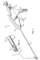
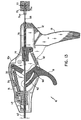
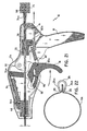
- Fig. 1 is a perspective view of a surgical apparatus constructed in accordance with a preferred embodiment of the subject invention in a pre-operative condition;
- Fig. 2 is an enlarged perspective view of the distal end portion of the surgical apparatus of Fig. 1 illustrating the surgical clip releasably supported thereon;
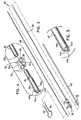
- Fig. 3 is an exploded perspective view of the elongate body of the surgical apparatus of Fig. 1 with the components thereof separated for ease of illustration;
- Fig. 4 is an enlarged perspective view of the distal end portion of the elongate body of Fig. 3 illustrating the surgical clip and clip support structure associated therewith;
- Fig. 5 is an enlarged perspective view of the distal end portion of the clip advancement tube of the elongate body illustrated in Fig. 3;
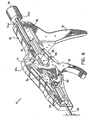
- Fig. 6 is a perspective view of the handle portion of the surgical apparatus of Fig. 1 with the left housing section removed to illustrate the internal components housed therein;
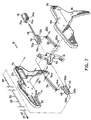
- Fig. 7 is an exploded perspective view of the handle portion shown in Fig. 6 with the components thereof separated for ease of illustration;
- Fig. 8 is an exploded perspective view of the locator and the distal end portion of the control rod to which the locator is mounted;
- Fig. 9 is an enlarged perspective view of the coupling area of the locator illustrated in Fig. 8;
- Fig. 10 is a perspective view of the locator in an expanded condition mounted to the distal end of the control rod;
- Fig. 11 is a perspective view of a cannula extending through a hole in the wall of a blood vessel with the elongate body of the surgical apparatus of Fig. 1 extended therethrough;
- Fig. 12 is an enlarged perspective view of the locator extended from the distal end portion of the surgical apparatus of Fig. 1 and collapsed within the cannula;
- Fig. 13 is a side elevational view in cross-section of the handle portion of the surgical apparatus of Fig. 1 illustrating the relative orientation of the internal components associated therewith in a pre-operative condition;
- Fig. 14 is a side-elevational view in cross-section of the handle portion of the surgical apparatus of Fig. 1 illustrating the relative orientation of the internal components associated therewith in a condition corresponding to the locator being disposed in a deployed position;
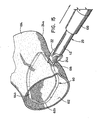
- Fig. 15 is a perspective view of a distal end portion of the elongate body of the surgical apparatus of Fig. 1 illustrating the locator disposed in a deployed position within the interior lumen of a blood vessel;
- Fig. 16 is a side elevational view in cross-section of the handle portion of the surgical apparatus of Fig. 1 illustrating the relative orientation of the components associated therewith in positions corresponding to the clip advancement tube being advanced toward a distal position;
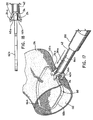
- Fig. 17 is a perspective view of the distal end portion of the elongate body of the surgical apparatus of Fig. 1 illustrating the clip advancement tube advanced distally to cause the surgical clip to move to an open position;
- Fig. 18 is a side-elevational view corresponding to Fig. 17 and illustrating the surgical clip in an open position;
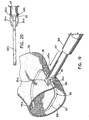
- Fig. 19 is a perspective view of the distal end portion of the elongate body of the surgical apparatus of Fig. 1 illustrating the clip advancement tube advanced to a distal-most position to cause the surgical clip to move to a closed position;
- Fig. 20 is a side elevational view corresponding to Fig. 19 and illustrating the surgical clip in a closed position;
- Fig. 21 is a side elevational view in cross-section of the handle portion of the surgical apparatus of Fig. 1 illustrating the relative orientation of the components associated therewith in positions corresponding to the locator being withdrawn to a retracted position; and
- Fig. 22 is a side elevational view of the surgical clip applied to the exterior wall of the blood vessel to close the hole formed therein.
-
- In the drawings and in the description which follows, the term "proximal", as is traditional, will refer to the end of the apparatus which is closest to the operator, while the term "distal" will refer to the end of the apparatus which is furthest from the operator.
- Referring now to the drawings wherein like reference numerals identify similar structural elements disclosed herein, there is illustrated in Fig. 1 a surgical apparatus constructed in accordance with a preferred embodiment of the subject application and designated generally by
reference numeral 10.Surgical apparatus 10 is adapted and configured to apply a surgical clip to the exterior wall of a blood vessel to at least partially close a hole formed therein during a catheterization procedure, such as, for example, an angioplasty or angiography procedure. - Referring to Fig. 1,
surgical apparatus 10 includes ahandle assembly 12 consisting of right and lefthousing sections 12a and 12b Which together define anelongated barrel portion 14, astationary handle 16 depending frombarrel portion 14, and a pivoting actuation handle or trigger 18 mounted for movement with respect tostationary handle 16. Anelongate body 20 extends distally from thebarrel portion 14 ofhandle assembly 12, and asurgical clip 22 is releasably supported on a distal end portion ofelongated body 20, as illustrated in Fig. 2. As best seen in Fig. 4,surgical clip 22 includes a pair of opposedclip legs 24a and 24b connected to one another by abail portion 26. Each clip leg is provided with a pair oftissue engagement projections 25 for securely engaging the exterior wall of the blood vessel to which it is applied (see Fig. 22).Clip legs 24a and 24b are normally biased into a closed position resulting from the overall configuration ofsurgical clip 22 and the material from which the clip is constructed. The material of construction may be selected from bio-compatible materials, including, for example, stainless steel, titanium, and tantalum. Other materials of construction such as bioabsorbable polymers are also envisioned. - Referring to Fig. 3, the
elongate body 20 ofsurgical apparatus 10 includes amain support shaft 30 having anelongate bore 30a extending therethrough.Support shaft 30 extends through thebarrel portion 14 ofhandle assembly 10 and is mounted adjacent a proximal end thereof in a conventional manner. Aclip support fixture 34 is mounted inaxial bore 30a adjacent the distal end ofsupport shaft 30. As best seen in Fig. 4,support fixture 34 is configured to releasably supportsurgical clip 22 and includes a pair of diametricallyopposed rails 36a and 36b dimensioned to interact with a crescent shapedaperture 38 defined in thebail portion 26 ofsurgical clip 22.Rails 36a and 36b terminate in distally extending camming ramps 40a and 40b, respectively, which effectuate movement ofclip legs 24a and 24b between closed and open positions assurgical clip 22 is advanced in a distal direction during a hole closing procedure. - Advancement of
surgical clip 22 in a distal direction relative to camming ramps 40a and 40b is accomplished through the axial translation of anelongate pusher tube 42.Pusher tube 42 is mounted coaxial withsupport shaft 30 and is configured to translate with respect thereto in response to manipulation of actuation handle 18 to drivesurgical clip 22 distally. As best seen in Fig. 5, spaced apart arcuate engagement fingers 44a and 44b project distally frompusher tube 42 to engage the crescent spacedaperture 38 defined in thebail portion 26 ofsurgical clip 22. Diametrically opposedelongate slots 46a and 46b are formed in the distal portion ofpusher tube 42 to accommodaterails 36a and 36b during the distal translation of the pusher tube with respect to supportshaft 30. - Referring now to Figs. 6 and 7, a
set pin 45 fixedly connects the proximal end ofpusher tube 42 to adistal actuation block 48 which is housed within thebarrel portion 14 ofhandle assembly 12.Actuation block 48 includes opposedlateral guide ribs 50a and 50b which translate within opposed guide slots formed in the interior surfaces of right and lefthousing sections 12a and 12b, i.e.,guide slot 53. Acoupling link 54 connectsdistal actuation block 48 to actuation handle 18 such that manipulation of actuation handle 18causes actuation block 48 to translate distally, urgingpusher tube 42 in a distal direction. Coupling pins 54a and 54b pivotally connectcoupling link 54 toactuation block 48 and actuation handle 18. - Referring now to Figs. 8-10,
surgical apparatus 10 also includes alocator 60 in the form of a collapsible loop adapted and configured to maintain the distal end portion ofelongate body 20 in a desired position with respect to the hole in the wall of a blood vessel during a hole closing procedure.Locator 60 includes a pair oflocator arms Locator arms proximal extension portions arcuate expansion portions 62b and 64b, respectively. As best seen in Fig. 9, the terminal end ofarcuate expansion portion 62b includes anengagement notch 63 for receiving and retaining acomplementary engagement finger 65 formed at the terminal end of arcuate expansion portion 64b. When engaged and situated in a relaxed unstressed condition,resilient expansion portions 62b and 64b form an endless loop-like structure. As best seen in Fig. 8, when assembled, the proximal ends ofextension portions coupling flange 66 which is provided at the distal end of anelongate control rod 68 which facilitates movement oflocator 60 with respect to supporttube 30 during a hole closing procedure. - Referring again to Figs. 6 and 7, the
elongate control rod 68 extends through theaxial bore 30a ofsupport tube 30, into thebarrel portion 14 ofhandle assembly 12, through theaxial bores barrel portion 14, and into theaxial bore 75a of acylindrical control knob 75 operatively associated withhandle assembly 12. The proximal end ofcontrol rod 68 is fixedly maintained withinaxial bore 75a ofcontrol knob 75 by a fastener 77 (see Fig. 13).Control knob 75 facilitates the longitudinal translation ofcontrol rod 68 between proximal and distal positions, and hence the movement oflocator 60 from a collapsed (stressed) position disposed within the axial bore 34a ofsupport fixture 34 to a deployed (unstressed) position extending from the distal end ofsupport fixture 34.Control knob 75 includes a pair ofengagement tabs housing sections 12a and 12b, i.e.,retention notch 76, whenlocator 60 is disposed in a deployed position. - With continuing reference to Figs. 6 and 7, an
elongate release tube 78 extends proximally from theproximal actuation block 70 to interact with, and effect the disengagement of,control knob 75 upon manipulation ofactuation handle 18. More particularly,proximal actuation block 70, which includesguide ribs 72a and 72b that translate within opposed guide slots formed inhousing sections 12a and 12b, i.e.,guide slot 73, is connected to actuation handle 18 by acoupling link 82. Coupling pins 82a and 82b pivotablyconnect coupling link 82 toactuation block 70 and actuation handle 18. Thus, manipulation of actuation handle 18causes actuation block 70 to translate in a proximal direction, whereuponrelease tube 78 enters theaxial bore 75a ofcontrol knob 75 and urges the control knob proximally to disengagetabs control knob 75 will not be released untilpusher tube 42 has been advanced to its distal-most position. - Referring now to Fig. 11, in use, the
elongate body 20 ofsurgical apparatus 10 is introduced into theinterior lumen 102 ofblood vessel 104 through aconventional cannula 100 which had previously been extended through thehole 106 formed in the wall ofblood vessel 104 during the catheterization procedure. Thereupon,locator 60 is moved distally through the translation ofcontrol knob 75 from its proximal-most position illustrated in Fig. 13 to its distal-most position illustrated in Fig. 14. Moreover,locator 60 is advanced from its proximal-most position disposed within the axial bore 34a ofclip support fixture 34 to its distal-most position extending from the distal end ofclip support fixture 34. At such a time, thearcuate expansion portions 62b and 64b oflocator arms cannula 100, as best seen in Fig. 12. Whencontrol knob 75 is in its proximal-most position shown in Fig. 14,engagement tabs barrel portion 14, thereby securing the longitudinal orientation ofcontrol rod 68 andlocator 60. - Referring now to Fig. 15, after
locator 60 is moved into its distal-most position,cannula 100 is withdrawn in a proximal direction with respect to elongatebody 20 to a retracted position. Consequently, thearcuate expansion portions 62b and 64b oflocator arms elongate body 20 in a desired position with respect to thehole 106 in the wall ofblood vessel 104. In this deployed position, the geometric plane defined bylocator 60 is oriented parallel to the elongation ofblood vessel 104. Accordingly, theopposed clip legs 24a and 24b ofsurgical clip 22 extend in a direction which is perpendicular to the elongation ofblood vessel 104. - Once
locator 60 is deployed, the clip application portion of the vascular hole closure procedure may commence. To applysurgical clip 22 to the exterior wall ofblood vessel 104 to at least partially close thehole 106 formed therein, actuation handle 18 is initially moved through the first segment of an actuation stroke, withguide pin 90 serving as the pivot point foractuation handle 18. During this time, actuation handle 18 causes thedistal actuation block 48 to translate from its proximal-most position illustrated in Fig. 14 to its distal-most position illustrated in Fig. 16 through a distance "xd" within thebarrel portion 14 of handle.assembly 12. As a result,pusher tube 42 is driven distally, urgingsurgical clip 22 in a distal direction. - Initially, during the distal advancement of
surgical clip 22, theopposed clip legs 24a and 24b ofsurgical clip 22 are moved to an open position as the clip translates with respect to camming ramps 40a and 40b, as illustrated in Figs 17 and 18. Subsequently, asactuation block 48 approaches its distal-most position withinbarrel portion 14,pusher tube 42 advancessurgical clip 22 past camming ramps 40a and 40b so thatclip legs 24a and 24b return to a closed portion, as illustrated in Figs. 19 and 20. More specifically, when camming ramps 40a and 40b meet the crescent shapedaperture 38 in thebail portion 26 of surgical 22,clip legs 24a and 24b return to their normally biased closed position. - Referring back to Fig. 14, prior to the manipulation of actuation handle 18 through the first segment of its actuating stroke, the proximal end of
release tube 78 is disposed slightly distal of theaxial bore 75a ofcontrol knob 75. As shown in Fig. 16, however, during the manipulation of actuation handle 18 through the first segment of its actuating stroke, theproximal actuation block 70 andrelease tube 78 translate in a proximal direction through a distance "xp" which is substantially less than the distance "xd" through which thedistal actuation block 48 travels during the same period of time. Consequently, during the first segment of the actuating stroke ofactuation handle 18, the proximal end ofrelease tube 78 translates only a short distance within theaxial bore 75a ofcontrol knob 75, remaining free from contact with the proximal wall ofaxial bore 75a, and having no effect of the longitudinal position ofcontrol knob 75. - However, as illustrated in Fig. 21, once the
distal actuation block 48 reaches its distal-most position, the pivot point of actuation handle 18 transfers fromguide pin 90 tocoupling pin 54a. As a result, the remaining portion of the actuating stroke of actuation handle 18 is guided by the interaction ofguide pin 90 and thearcuate guide slot 92 formed inactuation handle 18. Consequently, further manipulation of actuation handle 18 towardstationary handle 16 urgesproximal actuation block 70 in a proximal direction, drivingrelease tube 78 proximally. As a consequence,control knob 75 is urged proximally, causing the release ofengagement tabs barrel portion 14, and effectuating the proximal withdrawal ofcontrol rod 68 relative to supporttube 30. Accordingly, thearcuate expansion portions 62b and 64b oflocator 60 are withdrawn into the axial bore 34a ofsupport fixture 34, through the crescent shapedaperture 38 formed in thebail portion 26 ofsurgical clip 22. - Following the withdrawal of
locator 60 into the axial bore 34a ofsupport fixture 34, the distal end portion of theelongated body 20 ofsurgical apparatus 10 may be withdrawn from the surgical site. As best seen in Fig. 22, at the conclusion of the procedure, theopposed legs 24a and 24b ofsurgical clip 22 are securely engaged to the exterior wall ofblood vessel 104 such that the hole once formed therein is closed, thereby preventing blood from flowing therethrough.
Claims (12)
- An apparatus (10) for applying a surgical closure to an exterior wall of a blood vessel which defines an interior lumen of the blood vessel, to at least partially close a hole in the wall of the blood vessel, the apparatus comprising:the apparatus being characterized in that:a) a handle portion (12) including an actuation handle (18) mounted for movement through an actuating stroke;b) an elongate body (20) extending distally from the handle portion and dimensioned to extend through the hole in the wall of a blood vessel;c) a collapsed locator (60) operatively associated with the elongate body and mounted for movement from a collapsed retracted position disposed within a distal end portion of the elongate body to an expanded deployed position extending from the distal end portion of the elongate body, the locator being adapted and configured to expand within the interior lumen of the blood vessel in the deployed position to maintain the distal end portion of the elongate body in a desired location with respect to the hole in the blood vessel wall;d) the surgical closure;e) the surgical closure is a surgical clip (22) releasably supported on the distal end portion of the elongate body and configured for application to the exterior wall of the blood vessel to at least partially close the hole formed therein, the surgical clip having a pair of opposed clip legs (24 a, b) biased into a closed position and connected by a bail portion (26), the bail portion having an aperture provided therein to accommodate movement of the locator between the deployed position and the retracted position;f) an actuation assembly (48, 70) housed within the handle portion and operatively connected to the actuation handle such that movement of the actuation handle through a first segment of the actuating stroke effectuates longitudinal movement of the surgical clip toward the exterior wall of the blood vessel and movement of the actuation handle through a second segment of the actuating stroke effectuates movement of the collapsible locator from the deployed position to the retracted position ; andg) the locator forms, in its deployed position, a locator loop.
- An apparatus as recited in claim 1, wherein a control rod (68) extends from the handle portion through the elongate body portion and is mounted for movement between a proximal position and a distal position to effectuate the movement of the collapsed locator loop from the retracted position to the deployed position.
- An apparatus as recited in claim 2, wherein a control knob (75) is operatively mounted to a proximal end of the control rod to facilitate the longitudinal movement thereof and includes means (74 a, b) for releasably engaging the handle portion when the collapsible locator loop is disposed in the deployed position.
- An apparatus as recited in claim 3, wherein the elongate body portion includes an outer tubular member (42) mounted for axial movement with respect to the handle portion between a proximal position and a distal position for effectuating said longitudinal movement of the surgical clip.
- An apparatus as recited in claim 4, wherein a pair of diametrically opposed camming ramps (40 a, b) are formed on a support shaft (30) at a distal end of the elongate body, distal of the clip support position, the camming ramps causing the opposed legs of the surgical clip to move between-a closed position and an open position in response to longitudinal movement of the outer tubular member from the distal position toward the proximal position.
- An apparatus as recited in claim 5, wherein movement of the actuation handle through the first segment of the actuating stroke causes the outer tubular member to move from the proximal position to the distal position, and movement of the actuation handle through the second segment of the actuating stroke causes the control rod to move from the distal position to the proximal position.
- An apparatus as recited in claim 6, wherein movement of the actuation handle through the second segment of the actuating stroke releases the control knob from its engagement with the handle portion.
- An apparatus as recited in claim 7, wherein the actuating assembly includes a distal actuating member (48) connected to a proximal end of the outer tubular member and a proximal actuating member (70) connected to a release tube (78) which is dimensioned to interact with the actuator upon movement of the actuation handle through the second segment of the actuating stroke.
- An apparatus as recited in any one of the preceding claims, wherein at least a portion of the locator loop is formed from a material having shape memory characteristics.
- An apparatus as claimed in claim 3, wherein the means for releasably engaging the handle portion includes a pair of opposed locking tabs(74 a, b) configured to releasably engage complementary reception structures provided on a proximal end portion of the handle portion when the collapsible locator is disposed in the deployed position.
- An apparatus as claimed in any one of the preceding claims, wherein support structure (34) is provided adjacent a distal end of the elongate body for releasably supporting the surgical clip.
- An apparatus as claimed in claim 8, wherein a first control link (54) connects the distal actuating member to the actuation handle and second control link (82) connects the proximal actuating member to the actuation handle.
Applications Claiming Priority (2)
| Application Number | Priority Date | Filing Date | Title |
|---|---|---|---|
| US545974 | 1995-10-20 | ||
| US08/545,974 US5674231A (en) | 1995-10-20 | 1995-10-20 | Apparatus and method for vascular hole closure |
Publications (3)
| Publication Number | Publication Date |
|---|---|
| EP0774237A2 EP0774237A2 (en) | 1997-05-21 |
| EP0774237A3 EP0774237A3 (en) | 1997-07-30 |
| EP0774237B1 true EP0774237B1 (en) | 2003-04-02 |
Family
ID=24178314
Family Applications (1)
| Application Number | Title | Priority Date | Filing Date |
|---|---|---|---|
| EP96116909A Expired - Lifetime EP0774237B1 (en) | 1995-10-20 | 1996-10-21 | Apparatus for vascular hole closure |
Country Status (5)
| Country | Link |
|---|---|
| US (1) | US5674231A (en) |
| EP (1) | EP0774237B1 (en) |
| CA (1) | CA2188210C (en) |
| DE (1) | DE69627107T2 (en) |
| ES (1) | ES2192592T3 (en) |
Cited By (53)
| Publication number | Priority date | Publication date | Assignee | Title |
|---|---|---|---|---|
| USD611144S1 (en) | 2006-06-28 | 2010-03-02 | Abbott Laboratories | Apparatus for delivering a closure element |
| US7806904B2 (en) | 2000-12-07 | 2010-10-05 | Integrated Vascular Systems, Inc. | Closure device |
| US7806910B2 (en) | 2002-11-26 | 2010-10-05 | Abbott Laboratories | Multi-element biased suture clip |
| US7819895B2 (en) | 2000-01-05 | 2010-10-26 | Integrated Vascular Systems, Inc. | Vascular sheath with bioabsorbable puncture site closure apparatus and methods of use |
| US7828817B2 (en) | 2000-01-05 | 2010-11-09 | Integrated Vascular Systems, Inc. | Apparatus and methods for delivering a closure device |
| US7841502B2 (en) | 2007-12-18 | 2010-11-30 | Abbott Laboratories | Modular clip applier |
| US7850797B2 (en) | 2002-12-31 | 2010-12-14 | Integrated Vascular Systems, Inc. | Methods for manufacturing a clip and clip |
| US7850709B2 (en) | 2002-06-04 | 2010-12-14 | Abbott Vascular Inc. | Blood vessel closure clip and delivery device |
| US7867249B2 (en) | 2003-01-30 | 2011-01-11 | Integrated Vascular Systems, Inc. | Clip applier and methods of use |
| US7879071B2 (en) | 2000-12-07 | 2011-02-01 | Integrated Vascular Systems, Inc. | Closure device and methods for making and using them |
| US7887563B2 (en) | 2001-06-07 | 2011-02-15 | Abbott Vascular Inc. | Surgical staple |
| US7931669B2 (en) | 2000-01-05 | 2011-04-26 | Integrated Vascular Systems, Inc. | Integrated vascular device with puncture site closure component and sealant and methods of use |
| US8007512B2 (en) | 2002-02-21 | 2011-08-30 | Integrated Vascular Systems, Inc. | Plunger apparatus and methods for delivering a closure device |
| US8202293B2 (en) | 2003-01-30 | 2012-06-19 | Integrated Vascular Systems, Inc. | Clip applier and methods of use |
| US8202294B2 (en) | 2003-01-30 | 2012-06-19 | Integrated Vascular Systems, Inc. | Clip applier and methods of use |
| US8226681B2 (en) | 2007-06-25 | 2012-07-24 | Abbott Laboratories | Methods, devices, and apparatus for managing access through tissue |
| US8303624B2 (en) | 2010-03-15 | 2012-11-06 | Abbott Cardiovascular Systems, Inc. | Bioabsorbable plug |
| US8313497B2 (en) | 2005-07-01 | 2012-11-20 | Abbott Laboratories | Clip applier and methods of use |
| US8323312B2 (en) | 2008-12-22 | 2012-12-04 | Abbott Laboratories | Closure device |
| US8398676B2 (en) | 2008-10-30 | 2013-03-19 | Abbott Vascular Inc. | Closure device |
| US8398656B2 (en) | 2003-01-30 | 2013-03-19 | Integrated Vascular Systems, Inc. | Clip applier and methods of use |
| US8556932B2 (en) | 2011-05-19 | 2013-10-15 | Abbott Cardiovascular Systems, Inc. | Collapsible plug for tissue closure |
| US8556930B2 (en) | 2006-06-28 | 2013-10-15 | Abbott Laboratories | Vessel closure device |
| US8590760B2 (en) | 2004-05-25 | 2013-11-26 | Abbott Vascular Inc. | Surgical stapler |
| US8597325B2 (en) | 2000-12-07 | 2013-12-03 | Integrated Vascular Systems, Inc. | Apparatus and methods for providing tactile feedback while delivering a closure device |
| US8603116B2 (en) | 2010-08-04 | 2013-12-10 | Abbott Cardiovascular Systems, Inc. | Closure device with long tines |
| US8617184B2 (en) | 2011-02-15 | 2013-12-31 | Abbott Cardiovascular Systems, Inc. | Vessel closure system |
| US8672953B2 (en) | 2007-12-17 | 2014-03-18 | Abbott Laboratories | Tissue closure system and methods of use |
| US8690910B2 (en) | 2000-12-07 | 2014-04-08 | Integrated Vascular Systems, Inc. | Closure device and methods for making and using them |
| US8758398B2 (en) | 2006-09-08 | 2014-06-24 | Integrated Vascular Systems, Inc. | Apparatus and method for delivering a closure element |
| US8758400B2 (en) | 2000-01-05 | 2014-06-24 | Integrated Vascular Systems, Inc. | Closure system and methods of use |
| US8758399B2 (en) | 2010-08-02 | 2014-06-24 | Abbott Cardiovascular Systems, Inc. | Expandable bioabsorbable plug apparatus and method |
| US8784447B2 (en) | 2000-09-08 | 2014-07-22 | Abbott Vascular Inc. | Surgical stapler |
| US8808310B2 (en) | 2006-04-20 | 2014-08-19 | Integrated Vascular Systems, Inc. | Resettable clip applier and reset tools |
| US8821534B2 (en) | 2010-12-06 | 2014-09-02 | Integrated Vascular Systems, Inc. | Clip applier having improved hemostasis and methods of use |
| US8858594B2 (en) | 2008-12-22 | 2014-10-14 | Abbott Laboratories | Curved closure device |
| US8893947B2 (en) | 2007-12-17 | 2014-11-25 | Abbott Laboratories | Clip applier and methods of use |
| US8905937B2 (en) | 2009-02-26 | 2014-12-09 | Integrated Vascular Systems, Inc. | Methods and apparatus for locating a surface of a body lumen |
| US8920442B2 (en) | 2005-08-24 | 2014-12-30 | Abbott Vascular Inc. | Vascular opening edge eversion methods and apparatuses |
| US8926633B2 (en) | 2005-06-24 | 2015-01-06 | Abbott Laboratories | Apparatus and method for delivering a closure element |
| US9089674B2 (en) | 2000-10-06 | 2015-07-28 | Integrated Vascular Systems, Inc. | Apparatus and methods for positioning a vascular sheath |
| US9089311B2 (en) | 2009-01-09 | 2015-07-28 | Abbott Vascular Inc. | Vessel closure devices and methods |
| US9149276B2 (en) | 2011-03-21 | 2015-10-06 | Abbott Cardiovascular Systems, Inc. | Clip and deployment apparatus for tissue closure |
| US9173644B2 (en) | 2009-01-09 | 2015-11-03 | Abbott Vascular Inc. | Closure devices, systems, and methods |
| US9282965B2 (en) | 2008-05-16 | 2016-03-15 | Abbott Laboratories | Apparatus and methods for engaging tissue |
| US9314230B2 (en) | 2009-01-09 | 2016-04-19 | Abbott Vascular Inc. | Closure device with rapidly eroding anchor |
| US9332976B2 (en) | 2011-11-30 | 2016-05-10 | Abbott Cardiovascular Systems, Inc. | Tissue closure device |
| US9364209B2 (en) | 2012-12-21 | 2016-06-14 | Abbott Cardiovascular Systems, Inc. | Articulating suturing device |
| US9414824B2 (en) | 2009-01-16 | 2016-08-16 | Abbott Vascular Inc. | Closure devices, systems, and methods |
| US9414820B2 (en) | 2009-01-09 | 2016-08-16 | Abbott Vascular Inc. | Closure devices, systems, and methods |
| US9456811B2 (en) | 2005-08-24 | 2016-10-04 | Abbott Vascular Inc. | Vascular closure methods and apparatuses |
| US9486191B2 (en) | 2009-01-09 | 2016-11-08 | Abbott Vascular, Inc. | Closure devices |
| US9585647B2 (en) | 2009-08-26 | 2017-03-07 | Abbott Laboratories | Medical device for repairing a fistula |
Families Citing this family (123)
| Publication number | Priority date | Publication date | Assignee | Title |
|---|---|---|---|---|
| US6004341A (en) * | 1996-12-05 | 1999-12-21 | Loma Linda University Medical Center | Vascular wound closure device |
| US6425901B1 (en) | 1995-12-07 | 2002-07-30 | Loma Linda University Medical Center | Vascular wound closure system |
| US6287322B1 (en) | 1995-12-07 | 2001-09-11 | Loma Linda University Medical Center | Tissue opening locator and everter and method |
| US6524326B1 (en) | 1995-12-07 | 2003-02-25 | Loma Linda University Medical Center | Tissue opening locator and everter and method |
| GB2318295A (en) * | 1996-10-17 | 1998-04-22 | Malachy Gleeson | Wire-guided surgical stapler for closure of a puncture site in a blood vessel |
| US6036702A (en) | 1997-04-23 | 2000-03-14 | Vascular Science Inc. | Medical grafting connectors and fasteners |
| US5861005A (en) * | 1997-02-11 | 1999-01-19 | X-Site, L.L.C. | Arterial stapling device |
| AU4056499A (en) * | 1998-05-29 | 1999-12-20 | By-Pass, Ltd. | Vascular port device |
| US6964668B2 (en) | 1999-03-04 | 2005-11-15 | Abbott Laboratories | Articulating suturing device and method |
| US8137364B2 (en) | 2003-09-11 | 2012-03-20 | Abbott Laboratories | Articulating suturing device and method |
| ES2283316T3 (en) | 1999-09-13 | 2007-11-01 | Rex Medical, Lp | VASCULAR CLOSURE |
| US7662161B2 (en) | 1999-09-13 | 2010-02-16 | Rex Medical, L.P | Vascular hole closure device |
| US7942888B2 (en) | 1999-09-13 | 2011-05-17 | Rex Medical, L.P. | Vascular hole closure device |
| US8083766B2 (en) | 1999-09-13 | 2011-12-27 | Rex Medical, Lp | Septal defect closure device |
| US7341595B2 (en) | 1999-09-13 | 2008-03-11 | Rex Medical, L.P | Vascular hole closure device |
| US7267679B2 (en) | 1999-09-13 | 2007-09-11 | Rex Medical, L.P | Vascular hole closure device |
| US6911032B2 (en) | 1999-11-18 | 2005-06-28 | Scimed Life Systems, Inc. | Apparatus and method for compressing body tissue |
| US6428548B1 (en) * | 1999-11-18 | 2002-08-06 | Russell F. Durgin | Apparatus and method for compressing body tissue |
| US9579091B2 (en) * | 2000-01-05 | 2017-02-28 | Integrated Vascular Systems, Inc. | Closure system and methods of use |
| US6197042B1 (en) | 2000-01-05 | 2001-03-06 | Medical Technology Group, Inc. | Vascular sheath with puncture site closure apparatus and methods of use |
| DE60112887T2 (en) * | 2000-01-05 | 2006-06-14 | Integrated Vascular Sys Inc | DEVICE FOR CLOSING A POINT OF PUNCTURE |
| US6780197B2 (en) | 2000-01-05 | 2004-08-24 | Integrated Vascular Systems, Inc. | Apparatus and methods for delivering a vascular closure device to a body lumen |
| US6547806B1 (en) | 2000-02-04 | 2003-04-15 | Ni Ding | Vascular sealing device and method of use |
| US6547798B1 (en) * | 2000-05-04 | 2003-04-15 | Inbae Yoon | Ring applicator and method for applying elastic rings to anatomical tissue structures |
| US7780699B2 (en) | 2000-08-02 | 2010-08-24 | Loma Linda University Medical Center | Vascular wound closure device and method |
| US6890342B2 (en) | 2000-08-02 | 2005-05-10 | Loma Linda University | Method and apparatus for closing vascular puncture using hemostatic material |
| SE0002878D0 (en) * | 2000-08-11 | 2000-08-11 | Kimblad Ola | Device and method of treatment of atrioventricular regurgitation |
| US8551134B2 (en) * | 2000-09-01 | 2013-10-08 | Medtronic Vascular, Inc. | Wound site management and wound closure device |
| US6348064B1 (en) * | 2000-09-01 | 2002-02-19 | Angiolink Corporation | Wound site management and wound closure device |
| ZA200006432B (en) | 2000-09-08 | 2000-12-08 | Christy Cummins | Surgical micro-stapling instrument. |
| US6719777B2 (en) | 2000-12-07 | 2004-04-13 | Integrated Vascular Systems, Inc. | Closure device and methods for making and using them |
| IES20010749A2 (en) * | 2001-08-09 | 2003-02-19 | Christy Cummins | Surgical Stapling Device |
| IES20010748A2 (en) * | 2001-08-09 | 2003-02-19 | Christy Cummins | Surgical Stapling Device and Method |
| WO2004000134A2 (en) * | 2002-06-19 | 2003-12-31 | Tyco Healthcare Group, Lp | Method and apparatus for anastomosis including annular joining member |
| IES20030490A2 (en) * | 2002-07-03 | 2004-01-14 | Paul Hooi | Surgical stapling device |
| AU2003272314A1 (en) * | 2002-09-13 | 2004-04-30 | Damage Control Surgical Technologies, Inc. | Method and apparatus for vascular and visceral clipping |
| JP2006509595A (en) * | 2002-12-16 | 2006-03-23 | エドリッチ・ヴァスキュラー・ディヴァイシズ,インコーポレイテッド | Multiple stapling instruments for narrow vessels |
| DE10259411A1 (en) * | 2002-12-19 | 2004-07-08 | Forschungszentrum Karlsruhe Gmbh | Medical clip and device for applying such a device |
| US20040225301A1 (en) * | 2003-05-05 | 2004-11-11 | St. Jude Medical, Daig Division, Inc. | Loop closure apparatus and method |
| ATE502580T1 (en) | 2003-08-14 | 2011-04-15 | Univ Loma Linda Med | DEVICE FOR CLOSING VESSEL WOUNDS |
| US7462188B2 (en) | 2003-09-26 | 2008-12-09 | Abbott Laboratories | Device and method for suturing intracardiac defects |
| US7326230B2 (en) * | 2003-10-23 | 2008-02-05 | Sundaram Ravikumar | Vascular sealing device and method of use |
| US8128652B2 (en) | 2003-11-13 | 2012-03-06 | St. Jude Medical Puerto Rico Llc | Method and apparatus for sealing an internal tissue puncture incorporating a block and tackle |
| WO2005051206A1 (en) * | 2003-11-21 | 2005-06-09 | Vnus Medical Technologies, Inc. | Method and apparatus for treating a carotid artery |
| US7621937B2 (en) | 2003-12-03 | 2009-11-24 | St. Jude Medical Puerto Rico LC | Vascular sealing device with high surface area sealing plug |
| US7597705B2 (en) | 2003-12-03 | 2009-10-06 | St. Jude Medical Puerto Rico Llc | Vascular puncture seal anchor nest |
| US8882786B2 (en) * | 2004-02-17 | 2014-11-11 | Lawrence Livermore National Security, Llc. | System for closure of a physical anomaly |
| GB0420505D0 (en) | 2004-09-14 | 2004-10-20 | Wild Andrew M | Apparatus for dispensing surgical clips |
| US7182763B2 (en) * | 2004-11-23 | 2007-02-27 | Instrasurgical, Llc | Wound closure device |
| US7344544B2 (en) * | 2005-03-28 | 2008-03-18 | Cardica, Inc. | Vascular closure system |
| US7458978B1 (en) | 2005-03-28 | 2008-12-02 | Cardica, Inc. | Vascular closure system utilizing a staple |
| US7618436B2 (en) | 2005-04-12 | 2009-11-17 | St. Jude Medical Puerto Rico Llc | Tissue puncture closure device with scroll gear transmission tamping system |
| EP1871241B1 (en) | 2005-04-22 | 2012-12-19 | Rex Medical, L.P. | Closure device for left atrial appendage |
| US8083754B2 (en) | 2005-08-08 | 2011-12-27 | Abbott Laboratories | Vascular suturing device with needle capture |
| US20070060895A1 (en) * | 2005-08-24 | 2007-03-15 | Sibbitt Wilmer L Jr | Vascular closure methods and apparatuses |
| US8758397B2 (en) * | 2005-08-24 | 2014-06-24 | Abbott Vascular Inc. | Vascular closure methods and apparatuses |
| US8382794B2 (en) | 2006-01-04 | 2013-02-26 | St. Jude Medical Puerto Rico Llc | Balloon insertion apparatus and method of sealing a tissue puncture |
| US7875053B2 (en) * | 2006-09-15 | 2011-01-25 | Cardica, Inc. | Apparatus and method for closure of patent foramen ovale |
| US7749248B2 (en) * | 2006-09-18 | 2010-07-06 | St. Jude Medical Puerto Rico Llc | Flexible tamping device |
| WO2008066920A2 (en) * | 2006-11-28 | 2008-06-05 | Stryker Development Llc | Gastrotomy closure device |
| US8920305B2 (en) | 2007-01-19 | 2014-12-30 | Advanced Bariatric Technology, Llc | Vertically oriented band for stomach |
| US7766208B2 (en) * | 2007-01-24 | 2010-08-03 | Medtronic Vascular, Inc. | Low-profile vascular closure systems and methods of using same |
| US8128657B2 (en) * | 2007-02-27 | 2012-03-06 | Olympus Medical Systems Corp. | Suture instrument |
| US8308766B2 (en) * | 2007-02-27 | 2012-11-13 | Olympus Medical Systems Corp. | Endoscopic treatment instrument |
| US7533790B1 (en) | 2007-03-08 | 2009-05-19 | Cardica, Inc. | Surgical stapler |
| US7473258B2 (en) * | 2007-03-08 | 2009-01-06 | Cardica, Inc. | Surgical stapler |
| US8147504B2 (en) * | 2007-05-05 | 2012-04-03 | Medtronic, Inc. | Apparatus and methods for delivering fasteners during valve replacement |
| US8574244B2 (en) | 2007-06-25 | 2013-11-05 | Abbott Laboratories | System for closing a puncture in a vessel wall |
| EP2166954A1 (en) | 2007-07-13 | 2010-03-31 | Rex Medical, L.P. | Vascular hole closure device |
| EP2497520B1 (en) | 2007-07-18 | 2022-04-13 | Silk Road Medical, Inc. | Systems for establishing retrograde carotid arterial blood flow |
| US8858490B2 (en) | 2007-07-18 | 2014-10-14 | Silk Road Medical, Inc. | Systems and methods for treating a carotid artery |
| US8333787B2 (en) | 2007-12-31 | 2012-12-18 | St. Jude Medical Puerto Rico Llc | Vascular closure device having a flowable sealing material |
| US8568445B2 (en) | 2007-08-21 | 2013-10-29 | St. Jude Medical Puerto Rico Llc | Extra-vascular sealing device and method |
| US20090093826A1 (en) * | 2007-10-05 | 2009-04-09 | Cardica, Inc. | Patent Foramen Ovale Closure System |
| US8556931B2 (en) * | 2007-12-17 | 2013-10-15 | Abbott Laboratories | Methods for imaging a delivery system |
| US9282953B2 (en) | 2007-12-31 | 2016-03-15 | St. Jude Medical Puerto Rico Llc | Systems and methods for locating and closing a tissue puncture |
| US8840640B2 (en) | 2007-12-31 | 2014-09-23 | St. Jude Medical Puerto Rico Llc | Vascular closure device having an improved plug |
| EP3789069B1 (en) | 2008-02-05 | 2024-04-03 | Silk Road Medical, Inc. | Systems for establishing retrograde carotid arterial blood flow |
| US8920462B2 (en) | 2008-02-15 | 2014-12-30 | Rex Medical, L.P. | Vascular hole closure device |
| US20110029013A1 (en) | 2008-02-15 | 2011-02-03 | Mcguckin James F | Vascular Hole Closure Device |
| US8920463B2 (en) | 2008-02-15 | 2014-12-30 | Rex Medical, L.P. | Vascular hole closure device |
| US8070772B2 (en) | 2008-02-15 | 2011-12-06 | Rex Medical, L.P. | Vascular hole closure device |
| US9226738B2 (en) | 2008-02-15 | 2016-01-05 | Rex Medical, L.P. | Vascular hole closure delivery device |
| US8491629B2 (en) | 2008-02-15 | 2013-07-23 | Rex Medical | Vascular hole closure delivery device |
| US20090254121A1 (en) * | 2008-04-02 | 2009-10-08 | Cardica, Inc. | Vascular Closure with Multi-Pronged Clip |
| JP2012500049A (en) | 2008-08-13 | 2012-01-05 | シルク・ロード・メディカル・インコーポレイテッド | Suture delivery device |
| US8574245B2 (en) | 2008-08-13 | 2013-11-05 | Silk Road Medical, Inc. | Suture delivery device |
| US8900250B2 (en) | 2008-08-19 | 2014-12-02 | Cook Medical Technologies, LLC | Apparatus and methods for removing lymph nodes or anchoring into tissue during a translumenal procedure |
| AU2009288440B2 (en) | 2008-08-26 | 2015-04-23 | St Jude Medical, Inc. | Device and sealing component for sealing punctures |
| EP2328482B1 (en) | 2008-08-29 | 2012-09-26 | Cook Medical Technologies LLC | Stapling device for closing perforations |
| US8192461B2 (en) | 2008-09-11 | 2012-06-05 | Cook Medical Technologies Llc | Methods for facilitating closure of a bodily opening using one or more tacking devices |
| AU2009322353B2 (en) | 2008-12-05 | 2013-04-18 | Cook Medical Technologies Llc | Tissue anchors for purse-string closure of perforations |
| US8500760B2 (en) | 2008-12-09 | 2013-08-06 | Cook Medical Technologies Llc | Retractable tacking device |
| US8239004B2 (en) * | 2008-12-17 | 2012-08-07 | Abbott Laboratories | Methods for imaging an implant site |
| CA2747233C (en) | 2008-12-19 | 2014-08-12 | John A. Karpiel | Clip devices and methods of delivery and deployment |
| WO2010115072A1 (en) | 2009-04-03 | 2010-10-07 | Wilson-Cook Medical, Inc. | Tissue anchors and medical devices for rapid deployment of tissue anchors |
| AU2010232485B2 (en) | 2009-04-03 | 2013-11-07 | Cook Medical Technologies Llc | Medical devices, systems, and methods for rapid deployment and fixation of tissue anchors |
| CA2763133A1 (en) | 2009-05-28 | 2010-12-02 | Cook Medical Technologies Llc | Tacking device and methods of deployment |
| AU2010263224B2 (en) | 2009-06-26 | 2014-02-06 | Cook Medical Technologies Llc | Linear clamps for anastomosis |
| US20110034802A1 (en) * | 2009-08-05 | 2011-02-10 | Abbott Laboratories | Systems, methods, and apparatus for imaging an implantable device and methods for manufacturing |
| AU2010315651B2 (en) | 2009-11-03 | 2014-08-07 | Cook Medical Technologies Llc | Planar clamps for anastomosis |
| WO2011094700A1 (en) * | 2010-01-29 | 2011-08-04 | Advanced Bariatric Technology, Llc | Surgical clamp and surgical clamp installation tool |
| US8603121B2 (en) | 2010-04-14 | 2013-12-10 | Cook Medical Technologies Llc | Systems and methods for creating anastomoses |
| US9138212B1 (en) * | 2010-07-19 | 2015-09-22 | Cardica, Inc. | Anchor system for PFO closure |
| US9370353B2 (en) | 2010-09-01 | 2016-06-21 | Abbott Cardiovascular Systems, Inc. | Suturing devices and methods |
| US9414822B2 (en) | 2011-05-19 | 2016-08-16 | Abbott Cardiovascular Systems, Inc. | Tissue eversion apparatus and tissue closure device and methods for use thereof |
| WO2012170597A1 (en) | 2011-06-07 | 2012-12-13 | St. Jude Medical Puerto Rico Llc | Large bore closure device and methods |
| EP2747668B1 (en) | 2011-11-16 | 2017-01-04 | St. Jude Medical Puerto Rico LLC | Large bore vascular closure device with inner seal |
| EP2747667B1 (en) | 2011-11-16 | 2016-03-09 | St. Jude Medical Puerto Rico LLC | Vascular closure system |
| EP2747669B1 (en) | 2011-11-28 | 2017-01-04 | St. Jude Medical Puerto Rico LLC | Anchor device for large bore vascular closure |
| US9358077B2 (en) | 2012-03-14 | 2016-06-07 | St. Jude Medical Puerto Rico Llc | Markers for tissue tract depth indication and methods |
| US8858573B2 (en) | 2012-04-10 | 2014-10-14 | Abbott Cardiovascular Systems, Inc. | Apparatus and method for suturing body lumens |
| US9241707B2 (en) | 2012-05-31 | 2016-01-26 | Abbott Cardiovascular Systems, Inc. | Systems, methods, and devices for closing holes in body lumens |
| US9655606B2 (en) | 2012-08-03 | 2017-05-23 | St. Jude Medical Puerto Rico Llc | Large bore introducer with improved seal |
| US10159479B2 (en) | 2012-08-09 | 2018-12-25 | Silk Road Medical, Inc. | Suture delivery device |
| NZ704680A (en) | 2012-08-09 | 2017-05-26 | Advanced Bariatric Tech Llc | Polymer overmolded bariatric clamp and method of installing |
| US10016200B2 (en) | 2012-08-24 | 2018-07-10 | St. Jude Medical Puerto Rico Llc | Balloon bailout and bioadhesive delivery device for suture based closure and methods |
| US10136885B2 (en) | 2013-03-11 | 2018-11-27 | St. Jude Medical Puerto Rico Llc | Three suture large bore closure device and methods |
| US9055933B2 (en) | 2013-03-12 | 2015-06-16 | St. Jude Medical Puerto Rico Llc | Large bore closure secondary hemostasis bioadhesive delivery systems and methods |
| WO2015175537A1 (en) | 2014-05-16 | 2015-11-19 | Silk Road Medical, Inc. | Vessel access and closure assist system and method |
| AU2015306617B2 (en) | 2014-08-26 | 2019-10-24 | Advanced Bariatric Technology, Llc | Bariatric clamp with suture portions, magnetic inserts and curvature |
| WO2018009669A1 (en) | 2016-07-07 | 2018-01-11 | Advanced Bariatric Technology, Llc | Inflatable bariatric clamp |
| US11504105B2 (en) | 2019-01-25 | 2022-11-22 | Rex Medical L.P. | Vascular hole closure device |
Citations (1)
| Publication number | Priority date | Publication date | Assignee | Title |
|---|---|---|---|---|
| US5342393A (en) * | 1992-08-27 | 1994-08-30 | Duke University | Method and device for vascular repair |
Family Cites Families (45)
| Publication number | Priority date | Publication date | Assignee | Title |
|---|---|---|---|---|
| US2513771A (en) * | 1948-12-09 | 1950-07-04 | Carl T Williams | Incision closer |
| US4532134A (en) * | 1981-04-06 | 1985-07-30 | Malette William Graham | Method of achieving hemostasis, inhibiting fibroplasia, and promoting tissue regeneration in a tissue wound |
| US4854320A (en) * | 1983-10-06 | 1989-08-08 | Laser Surgery Software, Inc. | Laser healing method and apparatus |
| US4929240A (en) * | 1983-12-01 | 1990-05-29 | University Of New Mexico | Surgical clip and applier |
| US4890612A (en) | 1987-02-17 | 1990-01-02 | Kensey Nash Corporation | Device for sealing percutaneous puncture in a vessel |
| US4744364A (en) * | 1987-02-17 | 1988-05-17 | Intravascular Surgical Instruments, Inc. | Device for sealing percutaneous puncture in a vessel |
| USRE34866E (en) * | 1987-02-17 | 1995-02-21 | Kensey Nash Corporation | Device for sealing percutaneous puncture in a vessel |
| US4852568A (en) * | 1987-02-17 | 1989-08-01 | Kensey Nash Corporation | Method and apparatus for sealing an opening in tissue of a living being |
| US5030226A (en) * | 1988-01-15 | 1991-07-09 | United States Surgical Corporation | Surgical clip applicator |
| US5100420A (en) * | 1989-07-18 | 1992-03-31 | United States Surgical Corporation | Apparatus and method for applying surgical clips in laparoscopic or endoscopic procedures |
| US5254105A (en) * | 1988-05-26 | 1993-10-19 | Haaga John R | Sheath for wound closure caused by a medical tubular device |
| US5330445A (en) * | 1988-05-26 | 1994-07-19 | Haaga John R | Sheath for wound closure caused by a medical tubular device |
| US5053046A (en) * | 1988-08-22 | 1991-10-01 | Woodrow W. Janese | Dural sealing needle and method of use |
| FR2641692A1 (en) * | 1989-01-17 | 1990-07-20 | Nippon Zeon Co | Plug for closing an opening for a medical application, and device for the closure plug making use thereof |
| US5061274A (en) * | 1989-12-04 | 1991-10-29 | Kensey Nash Corporation | Plug device for sealing openings and method of use |
| EP0609212A4 (en) * | 1989-12-04 | 1995-04-19 | Kensey Nash Corp | Plug device for sealing openings and method of use. |
| US5217473A (en) * | 1989-12-05 | 1993-06-08 | Inbae Yoon | Multi-functional instruments and stretchable ligating and occluding devices |
| US5226908A (en) * | 1989-12-05 | 1993-07-13 | Inbae Yoon | Multi-functional instruments and stretchable ligating and occluding devices |
| US5021059A (en) * | 1990-05-07 | 1991-06-04 | Kensey Nash Corporation | Plug device with pulley for sealing punctures in tissue and methods of use |
| US5071417A (en) * | 1990-06-15 | 1991-12-10 | Rare Earth Medical Lasers, Inc. | Laser fusion of biological materials |
| DE4024106C1 (en) * | 1990-07-30 | 1992-04-23 | Ethicon Gmbh & Co Kg, 2000 Norderstedt, De | |
| US5391183A (en) * | 1990-09-21 | 1995-02-21 | Datascope Investment Corp | Device and method sealing puncture wounds |
| US5108421A (en) * | 1990-10-01 | 1992-04-28 | Quinton Instrument Company | Insertion assembly and method of inserting a vessel plug into the body of a patient |
| US5192300A (en) * | 1990-10-01 | 1993-03-09 | Quinton Instrument Company | Insertion assembly and method of inserting a vessel plug into the body of a patient |
| US5129882A (en) * | 1990-12-27 | 1992-07-14 | Novoste Corporation | Wound clotting device and method of using same |
| US5221259A (en) * | 1990-12-27 | 1993-06-22 | Novoste Corporation | Wound treating device and method of using same |
| US5156613A (en) * | 1991-02-13 | 1992-10-20 | Interface Biomedical Laboratories Corp. | Collagen welding rod material for use in tissue welding |
| US5310407A (en) * | 1991-06-17 | 1994-05-10 | Datascope Investment Corp. | Laparoscopic hemostat delivery system and method for using said system |
| NL9101051A (en) * | 1991-06-18 | 1993-01-18 | Ashridge Ag | CLOSING DEVICE FOR A VESSEL OR THE LIKE. |
| US5290310A (en) * | 1991-10-30 | 1994-03-01 | Howmedica, Inc. | Hemostatic implant introducer |
| US5282827A (en) * | 1991-11-08 | 1994-02-01 | Kensey Nash Corporation | Hemostatic puncture closure system and method of use |
| US5222974A (en) * | 1991-11-08 | 1993-06-29 | Kensey Nash Corporation | Hemostatic puncture closure system and method of use |
| US5411520A (en) * | 1991-11-08 | 1995-05-02 | Kensey Nash Corporation | Hemostatic vessel puncture closure system utilizing a plug located within the puncture tract spaced from the vessel, and method of use |
| US5242456A (en) * | 1991-11-21 | 1993-09-07 | Kensey Nash Corporation | Apparatus and methods for clamping tissue and reflecting the same |
| US5413571A (en) * | 1992-07-16 | 1995-05-09 | Sherwood Medical Company | Device for sealing hemostatic incisions |
| US5443481A (en) * | 1992-07-27 | 1995-08-22 | Lee; Benjamin I. | Methods and device for percutaneous sealing of arterial puncture sites |
| US5292332A (en) * | 1992-07-27 | 1994-03-08 | Lee Benjamin I | Methods and device for percutanceous sealing of arterial puncture sites |
| US5415657A (en) * | 1992-10-13 | 1995-05-16 | Taymor-Luria; Howard | Percutaneous vascular sealing method |
| US5304184A (en) * | 1992-10-19 | 1994-04-19 | Indiana University Foundation | Apparatus and method for positive closure of an internal tissue membrane opening |
| US5383897A (en) * | 1992-10-19 | 1995-01-24 | Shadyside Hospital | Method and apparatus for closing blood vessel punctures |
| US5417699A (en) * | 1992-12-10 | 1995-05-23 | Perclose Incorporated | Device and method for the percutaneous suturing of a vascular puncture site |
| US5383896A (en) * | 1993-05-25 | 1995-01-24 | Gershony; Gary | Vascular sealing device |
| US5383899A (en) * | 1993-09-28 | 1995-01-24 | Hammerslag; Julius G. | Method of using a surface opening adhesive sealer |
| US5370660A (en) * | 1993-11-01 | 1994-12-06 | Cordis Corporation | Apparatus and method for delivering a vessel plug into the body of a patient |
| US5443477A (en) * | 1994-02-10 | 1995-08-22 | Stentco, Inc. | Apparatus and method for deployment of radially expandable stents by a mechanical linkage |
-
1995
- 1995-10-20 US US08/545,974 patent/US5674231A/en not_active Expired - Lifetime
-
1996
- 1996-10-18 CA CA002188210A patent/CA2188210C/en not_active Expired - Fee Related
- 1996-10-21 DE DE69627107T patent/DE69627107T2/en not_active Expired - Lifetime
- 1996-10-21 EP EP96116909A patent/EP0774237B1/en not_active Expired - Lifetime
- 1996-10-21 ES ES96116909T patent/ES2192592T3/en not_active Expired - Lifetime
Patent Citations (1)
| Publication number | Priority date | Publication date | Assignee | Title |
|---|---|---|---|---|
| US5342393A (en) * | 1992-08-27 | 1994-08-30 | Duke University | Method and device for vascular repair |
Cited By (91)
| Publication number | Priority date | Publication date | Assignee | Title |
|---|---|---|---|---|
| US7901428B2 (en) | 2000-01-05 | 2011-03-08 | Integrated Vascular Systems, Inc. | Vascular sheath with bioabsorbable puncture site closure apparatus and methods of use |
| US8758400B2 (en) | 2000-01-05 | 2014-06-24 | Integrated Vascular Systems, Inc. | Closure system and methods of use |
| US8758396B2 (en) | 2000-01-05 | 2014-06-24 | Integrated Vascular Systems, Inc. | Vascular sheath with bioabsorbable puncture site closure apparatus and methods of use |
| US7819895B2 (en) | 2000-01-05 | 2010-10-26 | Integrated Vascular Systems, Inc. | Vascular sheath with bioabsorbable puncture site closure apparatus and methods of use |
| US7828817B2 (en) | 2000-01-05 | 2010-11-09 | Integrated Vascular Systems, Inc. | Apparatus and methods for delivering a closure device |
| US8956388B2 (en) | 2000-01-05 | 2015-02-17 | Integrated Vascular Systems, Inc. | Integrated vascular device with puncture site closure component and sealant |
| US9050087B2 (en) | 2000-01-05 | 2015-06-09 | Integrated Vascular Systems, Inc. | Integrated vascular device with puncture site closure component and sealant and methods of use |
| US7931669B2 (en) | 2000-01-05 | 2011-04-26 | Integrated Vascular Systems, Inc. | Integrated vascular device with puncture site closure component and sealant and methods of use |
| US8784447B2 (en) | 2000-09-08 | 2014-07-22 | Abbott Vascular Inc. | Surgical stapler |
| US9060769B2 (en) | 2000-09-08 | 2015-06-23 | Abbott Vascular Inc. | Surgical stapler |
| US9402625B2 (en) | 2000-09-08 | 2016-08-02 | Abbott Vascular Inc. | Surgical stapler |
| US9089674B2 (en) | 2000-10-06 | 2015-07-28 | Integrated Vascular Systems, Inc. | Apparatus and methods for positioning a vascular sheath |
| US7879071B2 (en) | 2000-12-07 | 2011-02-01 | Integrated Vascular Systems, Inc. | Closure device and methods for making and using them |
| US8486108B2 (en) | 2000-12-07 | 2013-07-16 | Integrated Vascular Systems, Inc. | Closure device and methods for making and using them |
| US8603136B2 (en) | 2000-12-07 | 2013-12-10 | Integrated Vascular Systems, Inc. | Apparatus and methods for providing tactile feedback while delivering a closure device |
| US8690910B2 (en) | 2000-12-07 | 2014-04-08 | Integrated Vascular Systems, Inc. | Closure device and methods for making and using them |
| US7887555B2 (en) | 2000-12-07 | 2011-02-15 | Integrated Vascular Systems, Inc. | Closure device and methods for making and using them |
| US7806904B2 (en) | 2000-12-07 | 2010-10-05 | Integrated Vascular Systems, Inc. | Closure device |
| US8128644B2 (en) | 2000-12-07 | 2012-03-06 | Integrated Vascular Systems, Inc. | Closure device and methods for making and using them |
| US8182497B2 (en) | 2000-12-07 | 2012-05-22 | Integrated Vascular Systems, Inc. | Closure device |
| US8486092B2 (en) | 2000-12-07 | 2013-07-16 | Integrated Vascular Systems, Inc. | Closure device and methods for making and using them |
| US9585646B2 (en) | 2000-12-07 | 2017-03-07 | Integrated Vascular Systems, Inc. | Closure device and methods for making and using them |
| US8597325B2 (en) | 2000-12-07 | 2013-12-03 | Integrated Vascular Systems, Inc. | Apparatus and methods for providing tactile feedback while delivering a closure device |
| US9320522B2 (en) | 2000-12-07 | 2016-04-26 | Integrated Vascular Systems, Inc. | Closure device and methods for making and using them |
| US9554786B2 (en) | 2000-12-07 | 2017-01-31 | Integrated Vascular Systems, Inc. | Closure device and methods for making and using them |
| US8236026B2 (en) | 2000-12-07 | 2012-08-07 | Integrated Vascular Systems, Inc. | Closure device and methods for making and using them |
| US8257390B2 (en) | 2000-12-07 | 2012-09-04 | Integrated Vascular Systems, Inc. | Closure device and methods for making and using them |
| US7887563B2 (en) | 2001-06-07 | 2011-02-15 | Abbott Vascular Inc. | Surgical staple |
| US7918873B2 (en) | 2001-06-07 | 2011-04-05 | Abbott Vascular Inc. | Surgical staple |
| US8728119B2 (en) | 2001-06-07 | 2014-05-20 | Abbott Vascular Inc. | Surgical staple |
| US9498196B2 (en) | 2002-02-21 | 2016-11-22 | Integrated Vascular Systems, Inc. | Sheath apparatus and methods for delivering a closure device |
| US8579932B2 (en) | 2002-02-21 | 2013-11-12 | Integrated Vascular Systems, Inc. | Sheath apparatus and methods for delivering a closure device |
| US8007512B2 (en) | 2002-02-21 | 2011-08-30 | Integrated Vascular Systems, Inc. | Plunger apparatus and methods for delivering a closure device |
| US8192459B2 (en) | 2002-06-04 | 2012-06-05 | Abbott Vascular Inc. | Blood vessel closure clip and delivery device |
| US9295469B2 (en) | 2002-06-04 | 2016-03-29 | Abbott Vascular Inc. | Blood vessel closure clip and delivery device |
| US8469995B2 (en) | 2002-06-04 | 2013-06-25 | Abbott Vascular Inc. | Blood vessel closure clip and delivery device |
| US7850709B2 (en) | 2002-06-04 | 2010-12-14 | Abbott Vascular Inc. | Blood vessel closure clip and delivery device |
| US7806910B2 (en) | 2002-11-26 | 2010-10-05 | Abbott Laboratories | Multi-element biased suture clip |
| US8202283B2 (en) | 2002-12-31 | 2012-06-19 | Integrated Vascular Systems, Inc. | Methods for manufacturing a clip and clip |
| US7850797B2 (en) | 2002-12-31 | 2010-12-14 | Integrated Vascular Systems, Inc. | Methods for manufacturing a clip and clip |
| US8585836B2 (en) | 2002-12-31 | 2013-11-19 | Integrated Vascular Systems, Inc. | Methods for manufacturing a clip and clip |
| US7854810B2 (en) | 2002-12-31 | 2010-12-21 | Integrated Vascular Systems, Inc. | Methods for manufacturing a clip and clip |
| US8202293B2 (en) | 2003-01-30 | 2012-06-19 | Integrated Vascular Systems, Inc. | Clip applier and methods of use |
| US8398656B2 (en) | 2003-01-30 | 2013-03-19 | Integrated Vascular Systems, Inc. | Clip applier and methods of use |
| US11589856B2 (en) | 2003-01-30 | 2023-02-28 | Integrated Vascular Systems, Inc. | Clip applier and methods of use |
| US7867249B2 (en) | 2003-01-30 | 2011-01-11 | Integrated Vascular Systems, Inc. | Clip applier and methods of use |
| US7905900B2 (en) | 2003-01-30 | 2011-03-15 | Integrated Vascular Systems, Inc. | Clip applier and methods of use |
| US8926656B2 (en) | 2003-01-30 | 2015-01-06 | Integated Vascular Systems, Inc. | Clip applier and methods of use |
| US9398914B2 (en) | 2003-01-30 | 2016-07-26 | Integrated Vascular Systems, Inc. | Methods of use of a clip applier |
| US8202294B2 (en) | 2003-01-30 | 2012-06-19 | Integrated Vascular Systems, Inc. | Clip applier and methods of use |
| US9271707B2 (en) | 2003-01-30 | 2016-03-01 | Integrated Vascular Systems, Inc. | Clip applier and methods of use |
| US8529587B2 (en) | 2003-01-30 | 2013-09-10 | Integrated Vascular Systems, Inc. | Methods of use of a clip applier |
| US8590760B2 (en) | 2004-05-25 | 2013-11-26 | Abbott Vascular Inc. | Surgical stapler |
| US8926633B2 (en) | 2005-06-24 | 2015-01-06 | Abbott Laboratories | Apparatus and method for delivering a closure element |
| US8313497B2 (en) | 2005-07-01 | 2012-11-20 | Abbott Laboratories | Clip applier and methods of use |
| US8518057B2 (en) | 2005-07-01 | 2013-08-27 | Abbott Laboratories | Clip applier and methods of use |
| US9050068B2 (en) | 2005-07-01 | 2015-06-09 | Abbott Laboratories | Clip applier and methods of use |
| US8920442B2 (en) | 2005-08-24 | 2014-12-30 | Abbott Vascular Inc. | Vascular opening edge eversion methods and apparatuses |
| US9456811B2 (en) | 2005-08-24 | 2016-10-04 | Abbott Vascular Inc. | Vascular closure methods and apparatuses |
| US8808310B2 (en) | 2006-04-20 | 2014-08-19 | Integrated Vascular Systems, Inc. | Resettable clip applier and reset tools |
| USD611144S1 (en) | 2006-06-28 | 2010-03-02 | Abbott Laboratories | Apparatus for delivering a closure element |
| US8556930B2 (en) | 2006-06-28 | 2013-10-15 | Abbott Laboratories | Vessel closure device |
| US8758398B2 (en) | 2006-09-08 | 2014-06-24 | Integrated Vascular Systems, Inc. | Apparatus and method for delivering a closure element |
| US8226681B2 (en) | 2007-06-25 | 2012-07-24 | Abbott Laboratories | Methods, devices, and apparatus for managing access through tissue |
| US8893947B2 (en) | 2007-12-17 | 2014-11-25 | Abbott Laboratories | Clip applier and methods of use |
| US8672953B2 (en) | 2007-12-17 | 2014-03-18 | Abbott Laboratories | Tissue closure system and methods of use |
| US7841502B2 (en) | 2007-12-18 | 2010-11-30 | Abbott Laboratories | Modular clip applier |
| US8820602B2 (en) | 2007-12-18 | 2014-09-02 | Abbott Laboratories | Modular clip applier |
| US9282965B2 (en) | 2008-05-16 | 2016-03-15 | Abbott Laboratories | Apparatus and methods for engaging tissue |
| US9241696B2 (en) | 2008-10-30 | 2016-01-26 | Abbott Vascular Inc. | Closure device |
| US8657852B2 (en) | 2008-10-30 | 2014-02-25 | Abbott Vascular Inc. | Closure device |
| US8398676B2 (en) | 2008-10-30 | 2013-03-19 | Abbott Vascular Inc. | Closure device |
| US8323312B2 (en) | 2008-12-22 | 2012-12-04 | Abbott Laboratories | Closure device |
| US8858594B2 (en) | 2008-12-22 | 2014-10-14 | Abbott Laboratories | Curved closure device |
| US9173644B2 (en) | 2009-01-09 | 2015-11-03 | Abbott Vascular Inc. | Closure devices, systems, and methods |
| US9089311B2 (en) | 2009-01-09 | 2015-07-28 | Abbott Vascular Inc. | Vessel closure devices and methods |
| US9486191B2 (en) | 2009-01-09 | 2016-11-08 | Abbott Vascular, Inc. | Closure devices |
| US9314230B2 (en) | 2009-01-09 | 2016-04-19 | Abbott Vascular Inc. | Closure device with rapidly eroding anchor |
| US9414820B2 (en) | 2009-01-09 | 2016-08-16 | Abbott Vascular Inc. | Closure devices, systems, and methods |
| US9414824B2 (en) | 2009-01-16 | 2016-08-16 | Abbott Vascular Inc. | Closure devices, systems, and methods |
| US8905937B2 (en) | 2009-02-26 | 2014-12-09 | Integrated Vascular Systems, Inc. | Methods and apparatus for locating a surface of a body lumen |
| US9585647B2 (en) | 2009-08-26 | 2017-03-07 | Abbott Laboratories | Medical device for repairing a fistula |
| US8303624B2 (en) | 2010-03-15 | 2012-11-06 | Abbott Cardiovascular Systems, Inc. | Bioabsorbable plug |
| US8758399B2 (en) | 2010-08-02 | 2014-06-24 | Abbott Cardiovascular Systems, Inc. | Expandable bioabsorbable plug apparatus and method |
| US8603116B2 (en) | 2010-08-04 | 2013-12-10 | Abbott Cardiovascular Systems, Inc. | Closure device with long tines |
| US8821534B2 (en) | 2010-12-06 | 2014-09-02 | Integrated Vascular Systems, Inc. | Clip applier having improved hemostasis and methods of use |
| US8617184B2 (en) | 2011-02-15 | 2013-12-31 | Abbott Cardiovascular Systems, Inc. | Vessel closure system |
| US9149276B2 (en) | 2011-03-21 | 2015-10-06 | Abbott Cardiovascular Systems, Inc. | Clip and deployment apparatus for tissue closure |
| US8556932B2 (en) | 2011-05-19 | 2013-10-15 | Abbott Cardiovascular Systems, Inc. | Collapsible plug for tissue closure |
| US9332976B2 (en) | 2011-11-30 | 2016-05-10 | Abbott Cardiovascular Systems, Inc. | Tissue closure device |
| US9364209B2 (en) | 2012-12-21 | 2016-06-14 | Abbott Cardiovascular Systems, Inc. | Articulating suturing device |
Also Published As
| Publication number | Publication date |
|---|---|
| CA2188210C (en) | 2006-03-28 |
| CA2188210A1 (en) | 1997-04-21 |
| EP0774237A3 (en) | 1997-07-30 |
| US5674231A (en) | 1997-10-07 |
| ES2192592T3 (en) | 2003-10-16 |
| DE69627107D1 (en) | 2003-05-08 |
| EP0774237A2 (en) | 1997-05-21 |
| DE69627107T2 (en) | 2003-12-04 |
Similar Documents
| Publication | Publication Date | Title |
|---|---|---|
| EP0774237B1 (en) | Apparatus for vascular hole closure | |
| US6197042B1 (en) | Vascular sheath with puncture site closure apparatus and methods of use | |
| EP1593347B1 (en) | Apparatus for closing an opening in tissue | |
| EP0756851B1 (en) | Vascular hole closure | |
| US8758396B2 (en) | Vascular sheath with bioabsorbable puncture site closure apparatus and methods of use | |
| US8652149B2 (en) | Vascular hole closure | |
| US8956388B2 (en) | Integrated vascular device with puncture site closure component and sealant | |
| EP1526810B1 (en) | Apparatus for sealing surgical punctures | |
| US5350399A (en) | Percutaneous arterial puncture seal device and insertion tool therefore | |
| US7326230B2 (en) | Vascular sealing device and method of use | |
| CA2302626C (en) | Percutaneous hemostatic suturing device and method | |
| EP1933720B1 (en) | Vascular opening edge eversion apparatuses | |
| US20040068272A1 (en) | System for wound closure | |
| US20030009180A1 (en) | Vascular hole closure device |
Legal Events
| Date | Code | Title | Description |
|---|---|---|---|
| PUAI | Public reference made under article 153(3) epc to a published international application that has entered the european phase |
Free format text: ORIGINAL CODE: 0009012 |
|
| AK | Designated contracting states |
Kind code of ref document: A2 Designated state(s): DE ES FR GB IT |
|
| PUAL | Search report despatched |
Free format text: ORIGINAL CODE: 0009013 |
|
| AK | Designated contracting states |
Kind code of ref document: A3 Designated state(s): DE ES FR GB IT |
|
| 17P | Request for examination filed |
Effective date: 19970731 |
|
| RIN1 | Information on inventor provided before grant (corrected) |
Inventor name: HINCHLIFFE, PETER W.J. Inventor name: MANZO, SCOTT E. Inventor name: GREEN, DAVID T. |
|
| 17Q | First examination report despatched |
Effective date: 20020306 |
|
| GRAH | Despatch of communication of intention to grant a patent |
Free format text: ORIGINAL CODE: EPIDOS IGRA |
|
| RTI1 | Title (correction) |
Free format text: APPARATUS FOR VASCULAR HOLE CLOSURE |
|
| GRAH | Despatch of communication of intention to grant a patent |
Free format text: ORIGINAL CODE: EPIDOS IGRA |
|
| GRAA | (expected) grant |
Free format text: ORIGINAL CODE: 0009210 |
|
| AK | Designated contracting states |
Designated state(s): DE ES FR GB IT |
|
| REG | Reference to a national code |
Ref country code: GB Ref legal event code: FG4D |
|
| REF | Corresponds to: |
Ref document number: 69627107 Country of ref document: DE Date of ref document: 20030508 Kind code of ref document: P |
|
| REG | Reference to a national code |
Ref country code: ES Ref legal event code: FG2A Ref document number: 2192592 Country of ref document: ES Kind code of ref document: T3 |
|
| ET | Fr: translation filed | ||
| PLBE | No opposition filed within time limit |
Free format text: ORIGINAL CODE: 0009261 |
|
| STAA | Information on the status of an ep patent application or granted ep patent |
Free format text: STATUS: NO OPPOSITION FILED WITHIN TIME LIMIT |
|
| 26N | No opposition filed |
Effective date: 20040105 |
|
| PGFP | Annual fee paid to national office [announced via postgrant information from national office to epo] |
Ref country code: DE Payment date: 20101027 Year of fee payment: 15 |
|
| PGFP | Annual fee paid to national office [announced via postgrant information from national office to epo] |
Ref country code: IT Payment date: 20101028 Year of fee payment: 15 Ref country code: GB Payment date: 20101025 Year of fee payment: 15 |
|
| PGFP | Annual fee paid to national office [announced via postgrant information from national office to epo] |
Ref country code: ES Payment date: 20111026 Year of fee payment: 16 Ref country code: FR Payment date: 20111028 Year of fee payment: 16 |
|
| GBPC | Gb: european patent ceased through non-payment of renewal fee |
Effective date: 20121021 |
|
| REG | Reference to a national code |
Ref country code: FR Ref legal event code: ST Effective date: 20130628 |
|
| PG25 | Lapsed in a contracting state [announced via postgrant information from national office to epo] |
Ref country code: GB Free format text: LAPSE BECAUSE OF NON-PAYMENT OF DUE FEES Effective date: 20121021 Ref country code: DE Free format text: LAPSE BECAUSE OF NON-PAYMENT OF DUE FEES Effective date: 20130501 |
|
| REG | Reference to a national code |
Ref country code: DE Ref legal event code: R119 Ref document number: 69627107 Country of ref document: DE Effective date: 20130501 |
|
| PG25 | Lapsed in a contracting state [announced via postgrant information from national office to epo] |
Ref country code: FR Free format text: LAPSE BECAUSE OF NON-PAYMENT OF DUE FEES Effective date: 20121031 Ref country code: IT Free format text: LAPSE BECAUSE OF NON-PAYMENT OF DUE FEES Effective date: 20121021 |
|
| REG | Reference to a national code |
Ref country code: ES Ref legal event code: FD2A Effective date: 20140116 |
|
| PG25 | Lapsed in a contracting state [announced via postgrant information from national office to epo] |
Ref country code: ES Free format text: LAPSE BECAUSE OF NON-PAYMENT OF DUE FEES Effective date: 20121022 |