EP0773408B1 - Furnace inside state estimation control apparatus of pulverized coal combustion furnace - Google Patents
Furnace inside state estimation control apparatus of pulverized coal combustion furnace Download PDFInfo
- Publication number
- EP0773408B1 EP0773408B1 EP96117700A EP96117700A EP0773408B1 EP 0773408 B1 EP0773408 B1 EP 0773408B1 EP 96117700 A EP96117700 A EP 96117700A EP 96117700 A EP96117700 A EP 96117700A EP 0773408 B1 EP0773408 B1 EP 0773408B1
- Authority
- EP
- European Patent Office
- Prior art keywords
- furnace
- coal
- temperature
- cell
- gas
- Prior art date
- Legal status (The legal status is an assumption and is not a legal conclusion. Google has not performed a legal analysis and makes no representation as to the accuracy of the status listed.)
- Expired - Lifetime
Links
Images


Classifications
-
- F—MECHANICAL ENGINEERING; LIGHTING; HEATING; WEAPONS; BLASTING
- F23—COMBUSTION APPARATUS; COMBUSTION PROCESSES
- F23N—REGULATING OR CONTROLLING COMBUSTION
- F23N5/00—Systems for controlling combustion
- F23N5/003—Systems for controlling combustion using detectors sensitive to combustion gas properties
-
- F—MECHANICAL ENGINEERING; LIGHTING; HEATING; WEAPONS; BLASTING
- F23—COMBUSTION APPARATUS; COMBUSTION PROCESSES
- F23N—REGULATING OR CONTROLLING COMBUSTION
- F23N5/00—Systems for controlling combustion
-
- F—MECHANICAL ENGINEERING; LIGHTING; HEATING; WEAPONS; BLASTING
- F22—STEAM GENERATION
- F22B—METHODS OF STEAM GENERATION; STEAM BOILERS
- F22B35/00—Control systems for steam boilers
- F22B35/18—Applications of computers to steam boiler control
-
- F—MECHANICAL ENGINEERING; LIGHTING; HEATING; WEAPONS; BLASTING
- F23—COMBUSTION APPARATUS; COMBUSTION PROCESSES
- F23N—REGULATING OR CONTROLLING COMBUSTION
- F23N1/00—Regulating fuel supply
- F23N1/02—Regulating fuel supply conjointly with air supply
- F23N1/022—Regulating fuel supply conjointly with air supply using electronic means
-
- F—MECHANICAL ENGINEERING; LIGHTING; HEATING; WEAPONS; BLASTING
- F23—COMBUSTION APPARATUS; COMBUSTION PROCESSES
- F23N—REGULATING OR CONTROLLING COMBUSTION
- F23N2221/00—Pretreatment or prehandling
- F23N2221/10—Analysing fuel properties, e.g. density, calorific
-
- F—MECHANICAL ENGINEERING; LIGHTING; HEATING; WEAPONS; BLASTING
- F23—COMBUSTION APPARATUS; COMBUSTION PROCESSES
- F23N—REGULATING OR CONTROLLING COMBUSTION
- F23N2223/00—Signal processing; Details thereof
- F23N2223/08—Microprocessor; Microcomputer
-
- F—MECHANICAL ENGINEERING; LIGHTING; HEATING; WEAPONS; BLASTING
- F23—COMBUSTION APPARATUS; COMBUSTION PROCESSES
- F23N—REGULATING OR CONTROLLING COMBUSTION
- F23N2223/00—Signal processing; Details thereof
- F23N2223/40—Simulation
-
- F—MECHANICAL ENGINEERING; LIGHTING; HEATING; WEAPONS; BLASTING
- F23—COMBUSTION APPARATUS; COMBUSTION PROCESSES
- F23N—REGULATING OR CONTROLLING COMBUSTION
- F23N2225/00—Measuring
- F23N2225/08—Measuring temperature
- F23N2225/16—Measuring temperature burner temperature
-
- F—MECHANICAL ENGINEERING; LIGHTING; HEATING; WEAPONS; BLASTING
- F23—COMBUSTION APPARATUS; COMBUSTION PROCESSES
- F23N—REGULATING OR CONTROLLING COMBUSTION
- F23N2229/00—Flame sensors
- F23N2229/20—Camera viewing
-
- F—MECHANICAL ENGINEERING; LIGHTING; HEATING; WEAPONS; BLASTING
- F23—COMBUSTION APPARATUS; COMBUSTION PROCESSES
- F23N—REGULATING OR CONTROLLING COMBUSTION
- F23N2235/00—Valves, nozzles or pumps
- F23N2235/02—Air or combustion gas valves or dampers
- F23N2235/06—Air or combustion gas valves or dampers at the air intake
-
- F—MECHANICAL ENGINEERING; LIGHTING; HEATING; WEAPONS; BLASTING
- F23—COMBUSTION APPARATUS; COMBUSTION PROCESSES
- F23N—REGULATING OR CONTROLLING COMBUSTION
- F23N2237/00—Controlling
- F23N2237/16—Controlling secondary air
-
- F—MECHANICAL ENGINEERING; LIGHTING; HEATING; WEAPONS; BLASTING
- F23—COMBUSTION APPARATUS; COMBUSTION PROCESSES
- F23N—REGULATING OR CONTROLLING COMBUSTION
- F23N2239/00—Fuels
- F23N2239/02—Solid fuels
-
- F—MECHANICAL ENGINEERING; LIGHTING; HEATING; WEAPONS; BLASTING
- F23—COMBUSTION APPARATUS; COMBUSTION PROCESSES
- F23N—REGULATING OR CONTROLLING COMBUSTION
- F23N5/00—Systems for controlling combustion
- F23N5/02—Systems for controlling combustion using devices responsive to thermal changes or to thermal expansion of a medium
- F23N5/08—Systems for controlling combustion using devices responsive to thermal changes or to thermal expansion of a medium using light-sensitive elements
Definitions
- the present invention relates to a furnace inside state estimation control apparatus of a pulverized coal combustion furnace which estimates a furnace inside state of a combustion furnace provided with burners for burning pulverized coal pneumatically conveyed and controls a supply rate of the pulverized coal, a supply rate of air, etc. and, particularly to a calculation program for obtaining, by calculation, a gas composition distribution and a temperature distribution inside the combustion furnace.
- NO x nitrogen oxide
- a pulverized coal burning boiler a plurality of burners are provided on the wall of a furnace, and an after-air inlet port is provided in the upper portion of the burner stage. Number of burners used are changed or a rate of air supplied to the after-air inlet ports is adjusted depending on the load, but by doing so non-uniformity occurs in the distribution of temperature and/or the distribution of gas components in the furnace.
- a method is disclosed in Japanese Patent Application Laid-Open No.5-264005 where temperature inside a furnace and steam temperature at the exit of a primary heater are estimated by dividing the inside of the furnace into a plurality of sections by vertical plane and calculating temperature at the exit of the furnace and an amount of heat absorption of the water wall, using a physical model.
- An object of the present invention is to provide a furnace inside state estimation control apparatus of pulverized coal combustion furnace provided with means capable of estimating both the distribution of gas components and the distribution of temperature inside the combustion furnace by calculation, which furnace inside state estimation control apparatus is able to control operating conditions, based on the calculated result of the distribution of gas components and/or the distribution of temperature.
- this object is achieved by a furnace inside state estimation control apparatus according to claim 1.
- gas flow rate calculation, gas reaction amount calculation, coal combustion amount calculation and radiant heat transfer calculation, for each cell are executed on the basis of data (unchangeable information) inherent to the furnace design such as the furnace dimensions and operational information such as a coal supply rate, an air supply rate, etc.
- the gas reaction amount calculation for which longest time is required is simplified by referring to the table of air ratio of gas phase to gas composition, so that the time required for calculation can be drastically reduced.
- FIG.1 is a view showing the overall construction of a first embodiment of a pulverized coal burning boiler in accordance with the present invention.
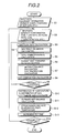
- FIG.2 is a flow chart showing the steps of estimating a state inside a furnace through calculation.
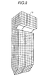
- FIG.3 is a view showing the construction inside a furnace 10 when the inside region of the furnace is divided into two-dimensional cells or three-dimensional cells.
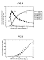
- FIG.4 is a characteristic graph showing the relationship between air ratio of gas phase and gas concentration.
- FIG.5 is a characteristic graph showing the relationship between air ratio of gas phase and NO x concentration.
- FIG.6 are charts showing an estimated result of distribution of temperature and distribution of gas components obtained through estimating calculation according to an estimating program.
- FIG.7 is a flow chart showing another embodiment of calculation steps in accordance with the present invention.
- FIG.8 is a view showing the overall construction of a second embodiment of a pulverized coal burning boiler in accordance with the present invention.
- FIG.9 is a flow chart showing a further embodiment of calculation steps in accordance with the present invention.
- FIG.10 is a view showing the overall construction of a third embodiment of a pulverized coal burning boiler in accordance with the present invention.
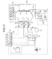
- FIG.11 is a view showing the overall construction of a fourth embodiment of a pulverized coal burning boiler in accordance with the present invention.
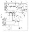
- FIG.12 is a view showing the overall construction of a fifth embodiment of a pulverized coal burning boiler in accordance with the present invention.
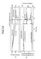
- FIG.13 is a chart showing characteristic of gas concentrations at burner load change.
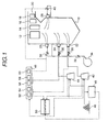
- FIG.1 is a view showing the overall construction of a first embodiment of a pulverized coal burning boiler in accordance with the present invention.
- a pulverized coal burning boiler has a furnace 10 as a main body of the boiler, and inside the furnace 10 heat transfer pipes (not shown) are arranged along walls of the furnace and a plurality of evaporators (super-heaters) 12, 14, 16, 18 are arranged at the exit side 20 of the furnace. Water or steam is supplied to these heat exchangers (which each are the generic name including the heat transfer pipes and the evaporators) through a feed water pipe (not shown), and each of the heat exchangers generates steam by burning in the furnace 10 and the steam is supplied to a steam turbine (not shown).
- a lower stage burner 22, an upper stage burner 24 and after-air injecting ports 26, 28 are arranged in a furnace wall of the furnace 10.
- the lower stage burner 22 and the upper stage burner 24 are arranged in a blowing box (not shown) for temporarily storing air, arranged in the furnace wall, and air is supplied to the lower stage burner 22 from a blower (plunger blower) 34 through air flow rate regulators 30, 32 and air is supplied to the upper stage burner 24 from the blower 34 through air flow rate regulators 36, 32. Further, air is also supplied to the after-air injecting ports 26, 28 through air flow rate regulators 38, 40.
- pulverized coal pulverized by a coal mill 42 is transmitted to the lower stage burner 22 as fuel
- pulverized coal pulverized by a coal mill 44 is transmitted to the upper stage burner 24 as fuel.
- Fuel coal is transmitted from a coal stock yard 46 to each of the coal mills 42, 44.
- the air and the pulverized coal supplied to the lower stage burner 22 are mixed and burned inside the furnace 10 to form flame inside the furnace 10.
- the air and the pulverized coal supplied to the upper stage burner 24 are mixed and burned inside the furnace 10 to form flame inside the furnace 10.
- the thermal energy is transmitted to the heat transfer pipes and the evaporators 12, 14, 16, 18 to generate steam in the heat transfer pipes and the evaporator. Then, the produced substances by burning of the air and the coal are exhausted from the exit 20.
- a controller 48 and a computer 50 are provided in order to control the air flow rates to the lower stage burner 22, the upper stage burner 24 and the after-air injecting ports 26, 28 and the pulverized coal flow rates to the lower stage burner 22 and the upper stage burner 24 and in order to estimate the burning state inside the furnace 10.
- the controller 48 has a lower stage burner air flow rate controller 52, a lower stage burner pulverized coal flow rate controller 54, an upper stage burner air flow rate controller 56, an upper stage burner pulverized coal flow rate controller 58 and an after-air injecting port air flow rate controller 60.
- the lower stage burner air flow rate controller 52 and the lower stage burner pulverized coal flow rate controller 54 execute control calculations according to a command from the computer 50, and the calculated result is input to the computer 50.
- the computer 50 stores information on transferring rates of pulverized coal from the coal mills 42, 44, pulverizing rates of pulverized coal of the coal mills 42, 44 and so on, and information from a coal analyzer 49, and the computer 50 outputs, to the coal mills 42, 44, commands such as commands for the transferring rates of pulverized coal, the pulverizing rates of pulverized coal and so on based on the information from the coal mills 42, 44 and the calculation result in each of the controllers 52, 54.
- the upper stage burner air flow rate controller 56, the upper stage burner pulverized coal flow rate controller 58 and the after-air injecting port air flow rate controller 60 execute control calculations according to a command from the computer 50, and output control signals according to the calculated results to the air flow rate regulators 30, 32, 36, 38, 40.
- the computer 50 stores an estimating program for calculating an estimation of a burning state inside the furnace 10 in addition to programs for executing various kinds of control calculation, and various kinds of input data are input to the computer 50.
- the input data is data inherent to furnace design such as dimensions of the furnace, number of the burners, type of burning (opposed or one-side), positions of the burners, spacing of the burners, position of the after-air injecting ports, spacing of the after-air injecting portions adjacent to each other and the like, and operating data such as characteristics of coal, for example, industrial analysis values of the coal, element analysis values of the coal, density of the coal, distribution of grain size (distribution of grain size of the pulverized coal) and so on, supplying rate of coal, air fuel ratio for the burner, supplying rate of after-air, water supplying rate to the heat pipes and the evaporators, temperature of the heat pipes and the evaporators and so on.
- fuel supplying rates supplying rate of pulverized coal supplied to each of the burners 22, 24
- characteristics of coal and so on is input to the computer as input data (S2).
- the computer 50 repeats execution of the processing from Step S3 to Step S7 based on the stored estimating program and the like and calculates to estimate a distribution of temperature inside the furnace 10 and a distribution of gas components inside the furnace 10 based on each of the processed results.
- the inside of the furnace 10 is divided into a plurality of cells (cells set for the purpose of calculation) of two-dimension (height ⁇ depth) or three-dimension (height ⁇ depth ⁇ width).
- FIG.3 shows an example of dividing the inside of the furnace 10 into a plurality of cells.
- reaction between O 2 and gas such as CO and so on is calculated in the gas reaction amount calculation (S4), and reaction between carbon (C) in solid state and the other molecules such as O 2 , CO 2 , H 2 O, that is, reaction amount between solid and gases is calculated in the coal-gas reaction calculation (S5).
- the equation (2) expresses a transportation equation, and the term Sreact indicates a heat generating rate produced by burning. The value is obtained from the gas reaction amount calculation (S4) and the coal-gas reaction calculation (S5).
- Srad indicates an amount of received heat by radiant heat transfer, and the amount of received heat is obtained from the radiant heat transfer rate calculation (S6).
- the gas reaction amount calculation uses a chemical equilibrium calculation method described in, for example, "Mechanical Engineering Hand book, Fundamental Part, A6 Thermal Engineering", p7 to p74 (published by The Japan Society of Mechanical Engineers).
- the gas reaction calculation may use a method dealing with a reaction velocity constant of Arrhenius type equation shown by the following equation (4) as described in "Mechanical Engineering Hand book, Fundamental Part, A6 Thermal Engineering”.
- the method has a disadvantage for practical use in that the calculation is very complex and takes a long time since coal burning produces many kinds of intermediate products during burning reaction process and there are chain reactions of the intermediate products.
- the method of using the chemical equilibrium calculation is not required to take the reaction of the intermediate products and can execute calculation immediately since the chemical equilibrium calculation method calculates the reaction by assuming that the reaction reaches the final state (chemical equilibrium state) and does not change further.
- Coal-gas reaction is a reaction between solid and gas, and the reaction velocity is extremely slow compared to gas reaction. Therefore, in the coal-gas reaction calculation (S5), the reaction velocity constant can be given by the equation of Arrhenius type shown by Equation (4).
- the reaction velocity (rate) of coal can be calculated from a reaction velocity constant, a partial pressure of the gases involving the reaction and a surface area of coal grains as shown by the following equation (5).
- An amount of heat Sreact generated by burning of coal can be calculated from the following equation (6) using a reaction velocity.
- kf A exp ⁇ -E/RT ⁇ wherein
- the radiant heat transfer rate calculation (S6) can employ a method in which an amount of heat Srad received by radiation heat transfer can be calculated from transmission equation for thermal radiation described in "Mechanical Engineering Hand book, Fundamental Part, A6 Thermal Engineering", p104 to p107.
- the individual calculated results affect each other of gas temperature and gas composition and amount, and gas flow rate. Accordingly, it is necessary to successively repeat the respective calculations until each of the calculated results converges. Therefore, at least one among temperatures of the respective cells obtained by the gas temperature calculation (S7) is compared with the temperature of the same cell obtained by the previous calculation. When the difference exceeds a preset allowable temperature difference, the above-mentioned calculation from (S3) to (S8) are repeatedly executed using the currently obtained temperature, and the calculations are repeated using newly obtained temperature until difference to the above-mentioned previous calculated value converges within the allowable temperature difference.
- the cell in which the converging condition is judged can be at any position inside the combustion furnace, it is desirable for conversion judgement in the calculation of the entire combustion furnace to use a cell at the outlet of the combustion furnace. Further, as the calculated results for the conversion judgment, gas composition and amount, gas flow rate can be used.
- a distribution of gas components and a distribution of temperature inside the furnace are calculated from the respective calculated results (S10).
- the calculated results are transmitted from the computer 50 to a display and/or a printer (not shown), and the distribution of gas components and the distribution of temperature inside the furnace, for example, those shown in FIG.6 (a) and (b) are displayed on a screen of the display.
- FIG.7 is a flow chart showing an embodiment of gas reaction calculation in which a table of gas compositions (S41) as an index of air ratio of gas phase, and the gas reaction calculation is executed by referring to the table instead of executing chemical equilibrium calculation.
- Table 2 and Table 3 show the relationship between the air ratio and gas compositions. Different point between Table 2 and Table 3 is in gas temperature.
- Coal is burnt under the conditions of furnace inside temperature from 1000 K to 2500 K and the conditions of an air ratio of gas phase from 0.6 to 4.0.
- GAS COMPONENTS (mole ratio:-) Air ratio of gas phase N 2 O 2 CO 2 CO H 2 O H 2 0.62 6.42E-01 4.76E-27 1.08E-01 1.35E-01 2.23E-02 9.23E-02 0.67 6.61E-01 1.06E-20 1.07E-01 1.23E-01 4.30E-02 6.58E-02 0.72 6.77E-01 1.19E-16 1.10E-01 1.09E-01 5.86E-02 4.50E-02 0.76 6.92E-01 9.18E-14 1.17E-01 9.28E-02 6.90E-02 2.98E-02 0.81 7.05E-01 1.52E-11 1.25E-01 7.48E-02 7.54E-02 1.90E-02 0.86 7.18E-01 1.00E-09 1.36E-01 5.59E-02 7.90E-02 1.14E-02 0.91 7.29E-01 4.04E-08 1.47
- Velocities at which hydrogen portion and carbon portion of pulverized coal are released in the burning process are different. Therefore, regarding the table of gas components as an index of air ratio of gas phase, it is preferable to make tables not only for a case of changing enthalpies having gases but also for a case of changing ratios of hydrogen portion and carbon portion.
- Enthalpy is a function of temperature and specific heat of a gas.
- coal to be supplied may be changed with other coal during operation of the furnace. Further, the properties of coal such as contents of carbon and hydrogen, heat generation amount, ash content are different according to coal mining sites. Therefore, when the above-mentioned table of air ratio of gas phase to gas composition is prepared, it is desirable that the analyzer 49 shown in Fig. 1 is provided, characteristics such as element ratios of carbon, hydrogen and oxygen, heat generation amount, etc. in coal are examined, and a table of air ratio of gas phase to gas composition which accords with the characteristics of a coal is used when the coal is supplied into the combustion furnace.
- heat balance calculation (S11) is executed and then an amount of steam generation and temperature of the steam are calculated based on the result of the heat balance calculation (S12).
- an amount of heat received by the surface of the furnace wall can be calculated based on the result. Further, an amount of steam generated from the heat transfer pipes and the evaporators and temperatures of the heat transfer pipes and the evaporators can be calculated based on the amount of received and heat the thermal energy transferred to the heat exchangers inside the furnace 10 (S12). After that, the calculation time of the computer 50 is increased (S13), and it is judged whether the whole process is completed or not (S14). If the predetermined process is not completed, the processing is returned to the process of Step S2. If the predetermined process is completed, the processing is completed at this routine.
- the region inside the furnace 10 is divided into a plurality of two-dimensional or three-dimensional cells, and gas fluid flow, gas reaction, coal-gas reaction and radiant heat transfer for each of the cells are calculated using the invariant information (data specific to the furnace design) and the operating information under the condition that the gas composition in relation to the burning inside the furnace 10 satisfies chemical equilibrium in regard to gas phase, and then using the results the distribution of temperature and the distribution of gas components inside the furnace 10 are calculated and estimated. Therefore, the time required for the gas reaction calculation can be shortened.
- an amount of unburned portion can be obtained as a physical quantity in regard to burning at the exit 20.
- the calculated results as basic data for operating signals, and to compare each of the calculated results with each of preset values corresponding to the calculations and to correct an amount of fuel flow rate and an amount of air flow rate based on the compared results. For example, when an unburned portion increases, the unburned portion can be decreased by increasing an amount of air flow rate injected through the after-air injecting port 26.
- concentrations of the unburned portion, carbon monoxide, oxygen and a temperature of gas at the exit of the furnace 10 are calculated, and the calculated result are compared with preset values to perform control corresponding to the compared results.
- control is performed so that the compared result is brought within the range of the preset value while each value of the other items does not exceed each of the ranges of limit values.
- a burner load of the lower stage burner 22 is set higher within the range where stable burning limits of the burners 22, 24 do not exceed and a limit value of thermal distribution of the furnace 10 does not exceed.
- the heat load inside the furnace 10 can be known based on the calculation results according to the estimating program, and it is possible to employ the burning method in which the load of the burner 22 is set within the range of the heat load limit values of the furnace 10.
- control to increase the air ratio in the furnace 10 is performed by increasing the air flow rate injected through the burners 22, 24 and the after-air injecting ports 26, 28 so that the calculated result based on the estimating program approaches to the preset value.
- the increase of the air ratio is successively performed from the downstream region (upper portion in the side of the exit) of the furnace 10 when suppression of NO x is taken into consideration.
- This operation is a method in which the grain size of the coal supplied to the furnace 10 is fined. This can be attained by automatically adjusting vane angles, loads and classifiers of the coal mills 42, 44 based on signals for setting conditions of the coal mills 42, 44. As the grain size of the coal is fined, the amount of unburned portion in ash is decreased because of increasing of burnability but required power for pulverization is increased.
- FIG.8 and FIG.9 A second embodiment in accordance with the present invention will be described below, referring to FIG.8 and FIG.9.
- windows are provided on the wall surface of the furnace 10 and cameras 62, 64 for taking the state of flame inside the furnace 10 as images are also provided at the windows, and a distribution of temperature is obtained from the flame images by inputting the output signals of the cameras to an image processing apparatus 66 and the result is input to the computer 50.
- the computer 50 stores a program in relation to an algorithm for this purpose.
- the other points are the same as in the first embodiment.
- the steps S51 to S53 in regard to the image processing are added between the step S10 and the step S11 in FIG.9.
- the calculation in the steps S1 to S8 is only calculation of a furnace model and does not always realize the actual furnace operating state. Therefore, it is preferable that temperature measurement is performed on the actual furnace within a practical range and the distribution of temperature obtained by the calculation of the steps S1 to S8 is corrected using the measured result. It has been known that a distribution of temperature can be measured by taking an image of flame, converting the image into brightness information and performing image processing. By using this method, it is possible to measure temperature of an actual furnace. However, there is a structural limitation in a furnace in which cameras and sonic sensors can be installed, and number of temperature measured positions inside the furnace using these sensors is also limited to several points. Therefore, the calculation of the steps S1 to S8 are necessary.
- At least the heat transfer pipes 72, 74 among the heat transfer pipes 68, 70, 72, 74 provided on the furnace wall of the furnace 10 are provided with measurement devices 76, 78 for measuring temperature or pressure of the heat transfer pipes 72, 74, and a measured value of each of the measurement devices is input to the computer 50 through a signal processor 82, and the computer 50 calculates and estimates a thickness of ash attached to the heat transfer pipes 72, 74. When the calculated value exceeds a preset value, the ash attached to the heat transfer pipes 72, 74 is removed using soot blowers 84, 86, 88, 90.
- the other construction is the same as that in FIG.1.
- the computer 50 can calculate and estimate the ash thickness attached to the heat transfer pipes 72, 74 using the processed result from the signal processor 82 and the amount of transferred heat calculated according to the estimating program.
- a command for driving a soot blower fan 92 is output and an operator operates the fan 92.
- each of the soot blowers 84 to 90 As the fan 92 is operated, compressed air or steam is supplied from the fan 92 to each of the soot blowers 84 to 90 through flow regulators 94, 96, 98, 100.
- Each of the soot blowers 84, 86, 88, 90 is formed in a cylinder-shape, and a plurality of jet holes are formed in the middle of a pipe for each of the soot blowers 84, 86, 88, 90.
- compressed air or steam is jetted from each of the jet holes by driving of the fan 92, the ash attached to the heat transfer pipes 72, 74 is removed by the compressed air or the steam.
- the ash removal by the soot blower utilizes thermal shock by temperature difference between the substance attached to each of the heat transfer pipes 72, 74 and the substance jetted from each of the soot blowers, and the thermal shock affects life-time of the heat transfer pipes 72, 74. Therefore, the thickness of ash attached to each of the heat transfer pipes 72, 74 is individual calculated and estimated using the measured values measured by the measurement devices 78, 80 and the heat transfer rate obtained from the estimating program, and the ash removal operation only for a designated heat transfer pipe is performed by driving the fan 92 and opening a designated flow regulator among the flow regulators 94, 96, 98, 100 only when the calculated value exceeds the preset value.
- operation of the pulverized coal burning boiler is controlled by monitoring temperature and pressure of steam in the inlet side of a steam turbine 104 connected to an electric power generator 102.
- the other construction is the same as that in FIG.1.
- a spray apparatus 108 is provided in the middle of a pipe 106 for guiding steam from the evaporator 12 to the steam turbine 104, and the spray apparatus 108 mixes steam from the evaporator 12 with water input to a feed water pump 114 from a condenser 112 according to a control signal from a feed water system controller 110.
- the feed water pump 114 is connected to the heat transfer pipes 74, 72 and the evaporator 18 through a pipe 116. That is, heat generated inside the furnace 10 is absorbed to each of the evaporators 12, 14, 16, 18 and high temperature steam generated in the evaporator 12 is supplied to the steam turbine 104 through the spray apparatus 108, and the steam turbine 104 driven by the thermal energy drives the electric power generator 102. Steam passed through the steam turbine 104 is changed into water in the condenser 112, and water or steam is supplied to the heat transfer pipes 72, 74 by operation of the feed water pump 114.
- the computer 50 When the steam turbine 104 is being operated, the computer 50 successively calculates and estimates a burning state inside the furnace 10 and calculates an amount of heat in connection to water or steam supplied to the heat transfer pipes 72, 74 based on an estimated result of the distribution of gas components and the distribution of temperature inside the furnace 10, and thermal physical properties in regard to a heat transfer coefficient and a heat radiation coefficient of the heat transfer pipe 72 arranged in the exit 20 side of the furnace wall of the furnace 10. Further, the computer calculates pressure and temperature of steam at the exit of the heat transfer pipe 72 or entering to the steam turbine 104 based on the heat supplied to the water or steam supplied to the heat transfer pipes 72, 74. The calculated results are displayed as check information for the operator as well as printed out from a printer. The calculated results are compared to preset values for operation as basic information for operating signals. According to the compared results, control signals are output from the feed water system controller 110 to the spray apparatus 108 and the feed water pump 114.
- the output of the steam turbine 104 exceeds a preset value, and the temperature and the pressure of the steam exceed the allowable values of the materials composing the steam turbine and fatigue and break may occurs in the materials.
- the temperature and the pressure of the steam are lower than the preset values, steam is condensed inside the steam turbine 104 due to lowering of the temperature and the pressure of the steam, and corrosion of the turbine material and abnormal vibration may occur.
- the life-time of the steam turbine 104 may be shortened due to thermal fatigue of the material. Therefore, it is necessary that operation of the spray apparatus 108 is controlled so as to decrease the fluctuation of the temperature and the pressure of the steam.
- a burning state inside the furnace 10 is understood and an amount of heat absorbed to water or steam supplied to the heat transfer pipes 72, 74 is calculated, and from the calculated result pressure and temperature of steam flowing into the steam turbine are estimated, and according to the estimated result the spray apparatus 108 and the feed water pump 114 are controlled and a fuel supply rate to the burners 22, 24 is controlled.
- the pressure and the temperature of the steam at the inlet side of the steam turbine 104 can be maintained at the preset values with suppressing the frequency of using the spray apparatus 108.
- the temperature can be suppressed within the preset value by inputting an operating command to the feed water pump 114 to increase the feed water flow rate to the heat transfer pipe 74.
- the fuel supply rate to the burners 22, 24 it is possible to obtain a higher load response with satisfying limiting conditions such as thermal stress.
- the electric power generator 102 is connected to a steam turbine 104 and a steam turbine 118, and a spray apparatus 108 and a spray apparatus 120 are provided.
- Steam from the evaporator 12 is supplied to the steam turbine 118 through a pipe 122 and the spray apparatus 120, and steam from the heat transfer pipe 72 is supplied to the steam turbine 104 through a pipe 124 and the spray apparatus 108, and water from a feed water pump 114 is supplied to the heat transfer pipe 74 through a pipe 126, and further water from the feed water pump 114 is supplied to an evaporator 18 through a branch valve (flow control valve) 128 and a pipe 130.
- the other construction is the same as that of FIG.11.
- the control signal from the feed water system controller 110 is supplied to the spray apparatuses 108, 120 and at the same time supplied also to the feed water pump 114 and the branch valve 128. Further, the outlet side of the steam turbine is connected to the evaporator 18 through a pipe 130.
- a burning state inside the furnace 10 is understood and an amount of heat of water or steam flowing through the heat transfer pipes 72, 74 is calculated based on a calculated results according to the estimating program, and from the calculated result a pressure and a temperature of steam flowing into the steam turbines 104, 118 are estimated, and an amount of fuel supplied to the burners 22, 24 and an amount of feed water to the heat transfer pipe 74 and to the evaporator 18 are controlled using the estimated result.
- the pressure and the temperature at the inlet side of the steam turbines 104, 118 are maintained at preset values with suppressing the frequency of using the spray apparatuses 108, 120.
- opening of the branch valve 128 is made controllable in taking it into consideration to operate the pulverized coal burning boiler with partial load by stopping the upper stage burner 24. That is, during partial load operation, there are some cases where the heat absorption inside the furnace 10 becomes large and the heat absorption of the evaporator 18 arranged in the exit 20 side of the furnace 10 becomes small. In such a case, pressure and temperature of steam obtained through each of the heat transfer pipes 72, 74 are fluctuated.
- the temperature and the pressure at the inlet side of each of the steam turbines 104, 118 can be estimated even when different temperature and different pressure steam flows into each of the steam turbines 104, 118.
- the temperature and the pressure at the inlet side of each of the steam turbines 104, 118 can be maintained at the preset values, for example, by increasing the feed water flow rate to the heat transfer pipe 74 and decreasing the feed water flow rate to the evaporator 18 through operating the branch valve 128.
- the aforementioned embodiments have described the pulverized coal burning boiler of one-side burning type in which the burners 22, 24 are arranged on one side of the furnace wall of the furnace 10.
- the present invention can be applied to a furnace of opposite burning type in which a plurality of burners are oppositely arranged or a furnace of corner firing type in which swirl flow is formed in the horizontal direction inside the furnace.
- FIG.13 is one of the examples which shows change in carbon monoxide concentration inside the furnace 10 when burners of three-stage construction are provided in the furnace 10, and operation of the burner in the first stage is stopped as the load is being decreased.
- pulverized coal inside the pulverized coal pipe is usually released by injecting air into the pulverized coal pipe pulsatively so as to prevent the pulverized coal remaining the pulverized coal pipe from fine-particle explosion or abnormal burning.
- high concentration pulverized coal is released in the furnace 10 in a moment. Therefore, an air ratio of the furnace 10 is decreased in a moment, and consequently the concentration of CO and the concentration of unburned portion in ash are increased.
- a method of suppressing increase in the concentration of CO and the concentration of unburned portion in ash there has been a method of increasing air flow rate in the after-air injecting port. However, it is difficult to match the timing for injecting air properly.
- an amount of air at the after-air injecting port can be increased and decreased by predicting a time lag between injection of remaining pulverized coal from the after-air injecting port and mixing of the injected pulverized coal with air, and the amounts of CO and unburned portion in ash can be suppressed below the limit values with a minimum necessary amount of air as shown in the figure by the reference characters a and b.
- the gas reaction when fluid flow, gas reaction, coal-gas reaction, radiant heat transfer in each of the cells are calculated based on data specific to a furnace design and operating information, the gas reaction is calculated under a condition that a chemical equilibrium is satisfied. Therefore, the calculation of gas reaction can be simplified and accordingly the burning state can be rapidly estimated.
- gas reaction can be calculated by searching a table by which gas compositions can be obtained with indexes of air ratio of gas phase and enthalpy of gas phase. Therefore, calculation of gas reaction can be further simplified.
Landscapes
- Engineering & Computer Science (AREA)
- Chemical & Material Sciences (AREA)
- Combustion & Propulsion (AREA)
- Mechanical Engineering (AREA)
- General Engineering & Computer Science (AREA)
- Physics & Mathematics (AREA)
- Thermal Sciences (AREA)
- Regulation And Control Of Combustion (AREA)
- Fixing For Electrophotography (AREA)
- Control Or Security For Electrophotography (AREA)
Description
- The present invention relates to a furnace inside state estimation control apparatus of a pulverized coal combustion furnace which estimates a furnace inside state of a combustion furnace provided with burners for burning pulverized coal pneumatically conveyed and controls a supply rate of the pulverized coal, a supply rate of air, etc. and, particularly to a calculation program for obtaining, by calculation, a gas composition distribution and a temperature distribution inside the combustion furnace.
- Burning of coal exhausts an environmental pollution substance of nitrogen oxide (NOx). There have been proposed various kinds of burning method to reduce an amount of exhausted NOx. However, in order to reduce an amount of exhausted NOx, it is necessary to understand a state inside the furnace. In a pulverized coal burning boiler, a plurality of burners are provided on the wall of a furnace, and an after-air inlet port is provided in the upper portion of the burner stage. Number of burners used are changed or a rate of air supplied to the after-air inlet ports is adjusted depending on the load, but by doing so non-uniformity occurs in the distribution of temperature and/or the distribution of gas components in the furnace. Further, there is difference in flame states of the burners due to difference in pressure loss of piping systems for supplying the pulverized coal and air. Therefore, it is necessary to perform proper control by observing the inside of the furnace to know from which portion NOx, carbon monoxide and unburned coal are exhausted.
- If various kinds of meters can be directly inserted inside the furnace, it is easy to obtain the distribution of gas components and the distribution of temperature inside the furnace. However, since the inside of the furnace is in a high temperature state, it is practically impossible. Therefore, it is necessary to obtain the distribution of temperature and the distribution of gas components through calculation.
- A method is disclosed in Japanese Patent Application Laid-Open No.5-264005 where temperature inside a furnace and steam temperature at the exit of a primary heater are estimated by dividing the inside of the furnace into a plurality of sections by vertical plane and calculating temperature at the exit of the furnace and an amount of heat absorption of the water wall, using a physical model.
- In the conventional technology described above, a distribution of gas components inside a furnace is not obtained. Further, heat generating portions inside the furnace and the heat generating rate are empirically determined and incorporated into a physical model. Therefore, when arrangement of pulverized coal burners or load is largely changed, it is required to calculate again by changing the physical model. Furthermore, when a distribution of gas components in a furnace is known, it is easy to control burning since it can be known in which zone much NOx and carbon monoxide are generated.
- An object of the present invention is to provide a furnace inside state estimation control apparatus of pulverized coal combustion furnace provided with means capable of estimating both the distribution of gas components and the distribution of temperature inside the combustion furnace by calculation, which furnace inside state estimation control apparatus is able to control operating conditions, based on the calculated result of the distribution of gas components and/or the distribution of temperature.
- According to the invention this object is achieved by a furnace inside state estimation control apparatus according to
claim 1. - It is a particular advantage of the furnace inside state estimation control apparatus according to the invention that the calculation of complicated gas composition is simplified. This simplification is based upon the finding that the gas reaction amount calculation can be effected as an index of air ratio of gas phase under assumption of chemical equilibrium. Thereby preferably a table of air ratio of a gas phase to gas composition is used.
- According to the present invention, when gas flow rate calculation, gas reaction amount calculation, coal combustion amount calculation and radiant heat transfer calculation, for each cell are executed on the basis of data (unchangeable information) inherent to the furnace design such as the furnace dimensions and operational information such as a coal supply rate, an air supply rate, etc., the gas reaction amount calculation for which longest time is required is simplified by referring to the table of air ratio of gas phase to gas composition, so that the time required for calculation can be drastically reduced.
- Further, it is possible to achieve burning with less emission of nitrogen oxides by controlling operational conditions of the furnace on the basis of the furnace inside temperature distribution and the furnace inside gas components distribution, obtained according to the present invention.
- Embodiments of the present invention are described below with reference to the accompanying drawings in which:
- FIG.1 is a view showing the overall construction of a first embodiment of a pulverized coal burning boiler in accordance with the present invention.
- FIG.2 is a flow chart showing the steps of estimating a state inside a furnace through calculation.
- FIG.3 is a view showing the construction inside a
furnace 10 when the inside region of the furnace is divided into two-dimensional cells or three-dimensional cells. - FIG.4 is a characteristic graph showing the relationship between air ratio of gas phase and gas concentration.
- FIG.5 is a characteristic graph showing the relationship between air ratio of gas phase and NOx concentration.
- FIG.6 are charts showing an estimated result of distribution of temperature and distribution of gas components obtained through estimating calculation according to an estimating program.
- FIG.7 is a flow chart showing another embodiment of calculation steps in accordance with the present invention.
- FIG.8 is a view showing the overall construction of a second embodiment of a pulverized coal burning boiler in accordance with the present invention.
- FIG.9 is a flow chart showing a further embodiment of calculation steps in accordance with the present invention.
- FIG.10 is a view showing the overall construction of a third embodiment of a pulverized coal burning boiler in accordance with the present invention.
- FIG.11 is a view showing the overall construction of a fourth embodiment of a pulverized coal burning boiler in accordance with the present invention.
- FIG.12 is a view showing the overall construction of a fifth embodiment of a pulverized coal burning boiler in accordance with the present invention.
- FIG.13 is a chart showing characteristic of gas concentrations at burner load change.
- FIG.1 is a view showing the overall construction of a first embodiment of a pulverized coal burning boiler in accordance with the present invention. Referring to FIG.1, a pulverized coal burning boiler has a
furnace 10 as a main body of the boiler, and inside thefurnace 10 heat transfer pipes (not shown) are arranged along walls of the furnace and a plurality of evaporators (super-heaters) 12, 14, 16, 18 are arranged at theexit side 20 of the furnace. Water or steam is supplied to these heat exchangers (which each are the generic name including the heat transfer pipes and the evaporators) through a feed water pipe (not shown), and each of the heat exchangers generates steam by burning in thefurnace 10 and the steam is supplied to a steam turbine (not shown). Further, alower stage burner 22, anupper stage burner 24 and after-air injecting ports furnace 10. Thelower stage burner 22 and theupper stage burner 24 are arranged in a blowing box (not shown) for temporarily storing air, arranged in the furnace wall, and air is supplied to thelower stage burner 22 from a blower (plunger blower) 34 through airflow rate regulators upper stage burner 24 from theblower 34 through airflow rate regulators air injecting ports flow rate regulators coal mill 42 is transmitted to thelower stage burner 22 as fuel, and pulverized coal pulverized by acoal mill 44 is transmitted to theupper stage burner 24 as fuel. Fuel coal is transmitted from acoal stock yard 46 to each of thecoal mills lower stage burner 22 are mixed and burned inside thefurnace 10 to form flame inside thefurnace 10. The air and the pulverized coal supplied to theupper stage burner 24 are mixed and burned inside thefurnace 10 to form flame inside thefurnace 10. As the flame is formed inside thefurnace 10, the thermal energy is transmitted to the heat transfer pipes and theevaporators exit 20. - In the present embodiment, a
controller 48 and acomputer 50 are provided in order to control the air flow rates to thelower stage burner 22, theupper stage burner 24 and the after-air injecting ports lower stage burner 22 and theupper stage burner 24 and in order to estimate the burning state inside thefurnace 10. Thecontroller 48 has a lower stage burner airflow rate controller 52, a lower stage burner pulverized coalflow rate controller 54, an upper stage burner airflow rate controller 56, an upper stage burner pulverized coalflow rate controller 58 and an after-air injecting port airflow rate controller 60. - The lower stage burner air
flow rate controller 52 and the lower stage burner pulverized coalflow rate controller 54 execute control calculations according to a command from thecomputer 50, and the calculated result is input to thecomputer 50. Thecomputer 50 stores information on transferring rates of pulverized coal from thecoal mills coal mills coal analyzer 49, and thecomputer 50 outputs, to thecoal mills coal mills controllers flow rate controller 56, the upper stage burner pulverized coalflow rate controller 58 and the after-air injecting port airflow rate controller 60 execute control calculations according to a command from thecomputer 50, and output control signals according to the calculated results to the airflow rate regulators - Further, the
computer 50 stores an estimating program for calculating an estimation of a burning state inside thefurnace 10 in addition to programs for executing various kinds of control calculation, and various kinds of input data are input to thecomputer 50. The input data is data inherent to furnace design such as dimensions of the furnace, number of the burners, type of burning (opposed or one-side), positions of the burners, spacing of the burners, position of the after-air injecting ports, spacing of the after-air injecting portions adjacent to each other and the like, and operating data such as characteristics of coal, for example, industrial analysis values of the coal, element analysis values of the coal, density of the coal, distribution of grain size (distribution of grain size of the pulverized coal) and so on, supplying rate of coal, air fuel ratio for the burner, supplying rate of after-air, water supplying rate to the heat pipes and the evaporators, temperature of the heat pipes and the evaporators and so on. - When a burning state inside the
furnace 10 is estimated by calculation based on the input data using thecomputer 50, processing as shown in FIG.2 is executed. - Firstly, the data inherent to the furnace design such as the shape of the
furnace 10, positions of the burners and the like is input to thecomputer 50 as input data (S1). Further, operating information such as fuel supplying rates (supplying rate of pulverized coal supplied to each of theburners 22, 24), air supplying rates (air supplying rate to each of the burners and the after-air injecting ports - As the input data is input to the
computer 50, thecomputer 50 repeats execution of the processing from Step S3 to Step S7 based on the stored estimating program and the like and calculates to estimate a distribution of temperature inside thefurnace 10 and a distribution of gas components inside thefurnace 10 based on each of the processed results. When the estimating calculation is performed, the inside of thefurnace 10 is divided into a plurality of cells (cells set for the purpose of calculation) of two-dimension (height × depth) or three-dimension (height × depth × width). Then, for each of the cells, gas flow rate calculation (S3) for calculating gas flow velocity (rate) in each of the cells, gas reaction amount calculation (S4), coal-gas reaction (coal combustion rate) calculation (S5), radiant heat transfer rate calculation (S6), enthalpy balance calculation and gas temperature calculation (S7), gas composition calculation (S8) and judgement of conversion (S9) are executed in taking effects between the cells into consideration. FIG.3 shows an example of dividing the inside of thefurnace 10 into a plurality of cells. - In the calculations Steps S3 to S8, reaction between O2 and gas such as CO and so on is calculated in the gas reaction amount calculation (S4), and reaction between carbon (C) in solid state and the other molecules such as O2, CO2, H2O, that is, reaction amount between solid and gases is calculated in the coal-gas reaction calculation (S5).
- In the gas flow rate calculation (S3), differential equations shown by the following equations (1) and (2) are calculated for each of the cells through finite differential method. The equation (1) of the both equations (1),(2) expresses conservation of mass for the gas components, and the term Sin in the equation (1) indicates the mass of gas components changed from pulverized coal by burning. The characters u and v indicate velocities of the gas in the lateral direction and in the perpendicular direction in each of the cells, respectively. As boundary condition of the velocity, the velocity which is 0 (zero) on wall surface, and calculated from an air injecting rate in the input data for a cell facing the burner nozzle and from the area of the burner nozzle obtained from an coordinate X, Y of each cell, is given. Further, the equation (2) expresses a transportation equation, and the term Sreact indicates a heat generating rate produced by burning. The value is obtained from the gas reaction amount calculation (S4) and the coal-gas reaction calculation (S5). The term Srad indicates an amount of received heat by radiant heat transfer, and the amount of received heat is obtained from the radiant heat transfer rate calculation (S6).
- x, y :
- coordinate
- u, v :
- velocity
- ρ :
- density.
- α :
- temperature diffusion coefficient
- H :
- enthalpy
- β :
- particle diffusion coefficient
- C :
- particle concentration
- The gas reaction amount calculation (S4) uses a chemical equilibrium calculation method described in, for example, "Mechanical Engineering Hand book, Fundamental Part, A6 Thermal Engineering", p7 to p74 (published by The Japan Society of Mechanical Engineers). In addition to the chemical equilibrium calculation method, the gas reaction calculation may use a method dealing with a reaction velocity constant of Arrhenius type equation shown by the following equation (4) as described in "Mechanical Engineering Hand book, Fundamental Part, A6 Thermal Engineering". However, the method has a disadvantage for practical use in that the calculation is very complex and takes a long time since coal burning produces many kinds of intermediate products during burning reaction process and there are chain reactions of the intermediate products. On the other hand, the method of using the chemical equilibrium calculation is not required to take the reaction of the intermediate products and can execute calculation immediately since the chemical equilibrium calculation method calculates the reaction by assuming that the reaction reaches the final state (chemical equilibrium state) and does not change further.
- There are two reaction types of coal burning, that is, gas reaction and coal-gas reaction. It has been found that the gas reaction can be arranged using an air ratio of gas phase and chemical equilibrium calculation can be applied. That is, it has been clarified that in the gas reaction an equilibrium state is satisfied and the chemical equilibrium calculation can be applied.
- The term "an air ratio of gas phase" means a ratio of an amount of actually injected air to an amount of air required for completely burning burnable components released in the form of gas from pulverized coal (Stoichiometric Ration of gas = SRg(-)).
- Coal-gas reaction is a reaction between solid and gas, and the reaction velocity is extremely slow compared to gas reaction. Therefore, in the coal-gas reaction calculation (S5), the reaction velocity constant can be given by the equation of Arrhenius type shown by Equation (4). The reaction velocity (rate) of coal can be calculated from a reaction velocity constant, a partial pressure of the gases involving the reaction and a surface area of coal grains as shown by the following equation (5). An amount of heat Sreact generated by burning of coal can be calculated from the following equation (6) using a reaction velocity.
- kf:
- reaction velocity constant
- E :
- activation energy of reaction
- R :
- general gas constant
- T :
- temperature
- A :
- frequency factor
- ki:
- reaction velocity constant of each reaction
- dWci/dt:
- reaction velocity of coal
- Pi:
- partial pressure of gas involving each reaction (i=O2, H2O, CO2)
- Sext:
- surface area of coal grains
- Examples of the reaction i are as follows;
- The radiant heat transfer rate calculation (S6) can employ a method in which an amount of heat Srad received by radiation heat transfer can be calculated from transmission equation for thermal radiation described in "Mechanical Engineering Hand book, Fundamental Part, A6 Thermal Engineering", p104 to p107.
- In the gas flow rate calculation (S3), the gas reaction amount calculation (S4), the coal combustion rate calculation (S5) and the radiant heat transfer rate calculation (S6), the individual calculated results affect each other of gas temperature and gas composition and amount, and gas flow rate. Accordingly, it is necessary to successively repeat the respective calculations until each of the calculated results converges. Therefore, at least one among temperatures of the respective cells obtained by the gas temperature calculation (S7) is compared with the temperature of the same cell obtained by the previous calculation. When the difference exceeds a preset allowable temperature difference, the above-mentioned calculation from (S3) to (S8) are repeatedly executed using the currently obtained temperature, and the calculations are repeated using newly obtained temperature until difference to the above-mentioned previous calculated value converges within the allowable temperature difference. Although the cell in which the converging condition is judged can be at any position inside the combustion furnace, it is desirable for conversion judgement in the calculation of the entire combustion furnace to use a cell at the outlet of the combustion furnace. Further, as the calculated results for the conversion judgment, gas composition and amount, gas flow rate can be used. When it is judged that each of the respective calculated results converges (S9), a distribution of gas components and a distribution of temperature inside the furnace are calculated from the respective calculated results (S10). The calculated results are transmitted from the
computer 50 to a display and/or a printer (not shown), and the distribution of gas components and the distribution of temperature inside the furnace, for example, those shown in FIG.6 (a) and (b) are displayed on a screen of the display. - Since the distribution of gas components and the distribution of temperature inside the furnace are known as described above, it can be understood in which portion inside the furnace imperfect burning occurs. Therefore, by adjusting a flow rate of pulverized coal and/or a flow rate of air supplied to a burner and/or an after-air injecting port near the portion, it is possible to perform burning with small NOx exhaust and small unburned substance.
- In pulverized coal burning, gas components such as oxygen, carbon dioxide, carbon monoxide, nitrogen, hydrogen, steam and so on are in an equilibrium state (an equilibrium condition) in gas phase. Therefore, an air ratio of gas phase and a gas concentration have a certain correlation. As an example, coals having characteristics shown in Table 1 were burned, and the relationship between the air ratio of gas phase and the gas concentration was investigated and the graphs shown in FIG.4 and FIG.5 are obtained. The graphs show results in a case of gas temperature of 1400 °C.
KIND OF COAL FUEL RATIO ASH PORTION (wt %) N PORTION (dry, ash free) (wt %) coal A 1.03 15.7 2.52 coal B 1.98 8.9 1.78 coal C 2.32 12.8 1.94 coal D 3.44 8.4 2.09 - From the above fact, in pulverized coal burning, concentrations of gas components such as oxygen, carbon dioxide and so on are singularly determined by an air ratio of gas phase, and accordingly the gas reaction calculation can be simplified.
- FIG.7 is a flow chart showing an embodiment of gas reaction calculation in which a table of gas compositions (S41) as an index of air ratio of gas phase, and the gas reaction calculation is executed by referring to the table instead of executing chemical equilibrium calculation.
- Examples of the index used for the gas reaction calculation in FIG.7 are shown in Table 2 and Table 3. Both of Table 2 and Table 3 show the relationship between the air ratio and gas compositions. Different point between Table 2 and Table 3 is in gas temperature. In Table 2 and Table 3, for example, E-17 indicates x10-17 (for example, 6.42E-01 = 6.42x10-01).
- Coal is burnt under the conditions of furnace inside temperature from 1000 K to 2500 K and the conditions of an air ratio of gas phase from 0.6 to 4.0.
GAS COMPONENTS (mole ratio:-) Air ratio of gas phase N2 O2 CO2 CO H2O H2 0.62 6.42E-01 4.76E-27 1.08E-01 1.35E-01 2.23E-02 9.23E-02 0.67 6.61E-01 1.06E-20 1.07E-01 1.23E-01 4.30E-02 6.58E-02 0.72 6.77E-01 1.19E-16 1.10E-01 1.09E-01 5.86E-02 4.50E-02 0.76 6.92E-01 9.18E-14 1.17E-01 9.28E-02 6.90E-02 2.98E-02 0.81 7.05E-01 1.52E-11 1.25E-01 7.48E-02 7.54E-02 1.90E-02 0.86 7.18E-01 1.00E-09 1.36E-01 5.59E-02 7.90E-02 1.14E-02 0.91 7.29E-01 4.04E-08 1.47E-01 3.69E-02 8.06E-02 6.17E-03 0.95 7.40E-01 1.70E-06 1.59E-01 1.82E-02 8.09E-02 2.53E-03 1.00 7.49E-01 9.72E-04 1.68E-01 1.73E-03 8.00E-02 2.09E-04 1.05 7.51E-01 9.71E-03 1.62E-01 3.61E-04 7.66E-02 4.48E-05 1.09 7.53E-01 1.83E-02 1.55E-01 1.60E-04 7.33E-02 2.07E-05 1.14 7.55E-01 2.62E-02 1.49E-01 8.13E-05 7.03E-02 1.10E-05 1.19 7.56E-01 3.35E-02 1.43E-01 4.43E-05 6.75E-02 6.29E-06 1.28 7.59E-01 4.65F-02 1.32E-01 1.47E-05 6.25E-02 2.28E-06 1.38 7.61E-01 5.78E-02 1.23E-01 5.37E-06 5.82E-02 9.10E-07 1.47 7.63E-01 6.76E-02 1.15E-01 2.11E-06 5.44E-02 3.89E-07 1.57 7.64E-01 7.62E-02 1.08E-01 8.75E-07 5.12E-02 1.75E-07 1.66 7.66E-01 8.38E-02 1.02E-01 3.81E-07 4.82E-02 8.25E-08 GAS COMPONENTS (mole ratio:-) Air ratio of gas phase N2 O2 CO2 CO H2O H2 0.62 6.42E-01 4.76E-27 1.08E-01 1.35E-^01 2.23E-02 9.23E-02 0.67 6.61E-01 1.06E-20 1.07E-01 1.23E-01 4.30E-02 6.58E-02 0.72 6.77E-01 1.19E-16 1.10E-01 1.09E-^01 5.86E-02 4.50E-02 0.76 6.92E-01 9.18E-14 1.17E-01 9.28E-02 6.90E-02 2.98E-02 0.81 7.05E-01 1.52E-11 1.25E-01 7.48E-02 7,54E-02 1.90E-02 0.86 7.18E-01 1.00E-09 1.36E-01 5.59E-02 7.90E-02 1.14E-02 0.91 7.29E-01 4.04E-08 1.47E-01 3.69E-02 8.06E-02 6.17E-03 0.95 7.40E-01 1.70E-06 1.59E-01 1.82E-02 8.06E-02 2.53E-03 1.00 7.49E-01 9.72E-04 1.68E-01 1.73E-03 8.00E-02 2.09E-04 1.05 7.51E-01 9.71E-03 1.62E-01 3.61E-04 7.66E-02 4.48E-05 1.09 7.53E-01 1.83E-02 1.55E-01 1.60E-04 7.33E-02 2.07E-05 1.14 7.55E-01 2.62E-02 1.49E-01 8.13E-05 7.03E-02 1.10E-05 1.19 7.56E-01 3.35E-02 1.43E-01 4.43E-05 6.75E-02 6.29E-06 1.28 7.59E-01 4.65E-02 1.32E-01 1.47E-05 6.25E-02 2.28E-06 1.38 7.61E-01 5.78E-02 1.23E-01 5.37E-06 5.82E-02 9.10E-07 1.47 7.63E-01 6.76E-02 1.15E-01 2.11E-06 5.44E-02 3.89E-07 1.57 7.64E-01 7.62E-02 1.08E-01 8.75E-07 5.12E-02 1.75E-07 1.66 7.66E-01 8.38E-02 1.02E-01 3.81E-07 4.82E-02 8.25E-08 - Velocities at which hydrogen portion and carbon portion of pulverized coal are released in the burning process are different. Therefore, regarding the table of gas components as an index of air ratio of gas phase, it is preferable to make tables not only for a case of changing enthalpies having gases but also for a case of changing ratios of hydrogen portion and carbon portion. Enthalpy is a function of temperature and specific heat of a gas.
- In the pulverized coal combustion furnace, in some cases, coal to be supplied may be changed with other coal during operation of the furnace. Further, the properties of coal such as contents of carbon and hydrogen, heat generation amount, ash content are different according to coal mining sites. Therefore, when the above-mentioned table of air ratio of gas phase to gas composition is prepared, it is desirable that the
analyzer 49 shown in Fig. 1 is provided, characteristics such as element ratios of carbon, hydrogen and oxygen, heat generation amount, etc. in coal are examined, and a table of air ratio of gas phase to gas composition which accords with the characteristics of a coal is used when the coal is supplied into the combustion furnace. - As shown in FIG.2 and FIG.7, after a distribution of temperature and a distribution of gas components inside the furnace are obtained, heat balance calculation (S11) is executed and then an amount of steam generation and temperature of the steam are calculated based on the result of the heat balance calculation (S12).
- When the distribution of temperature and the distribution of gas components inside the furnace is obtained, an amount of heat received by the surface of the furnace wall can be calculated based on the result. Further, an amount of steam generated from the heat transfer pipes and the evaporators and temperatures of the heat transfer pipes and the evaporators can be calculated based on the amount of received and heat the thermal energy transferred to the heat exchangers inside the furnace 10 (S12). After that, the calculation time of the
computer 50 is increased (S13), and it is judged whether the whole process is completed or not (S14). If the predetermined process is not completed, the processing is returned to the process of Step S2. If the predetermined process is completed, the processing is completed at this routine. - According to the present embodiment, the region inside the
furnace 10 is divided into a plurality of two-dimensional or three-dimensional cells, and gas fluid flow, gas reaction, coal-gas reaction and radiant heat transfer for each of the cells are calculated using the invariant information (data specific to the furnace design) and the operating information under the condition that the gas composition in relation to the burning inside thefurnace 10 satisfies chemical equilibrium in regard to gas phase, and then using the results the distribution of temperature and the distribution of gas components inside thefurnace 10 are calculated and estimated. Therefore, the time required for the gas reaction calculation can be shortened. - In the present embodiment, by multiplying the fluid flow (velocity) and the gas compositions in the cells facing the
exit 20 side of thefurnace 10, an amount of unburned portion can be obtained as a physical quantity in regard to burning at theexit 20. - Further, it is possible to use the calculated results as basic data for operating signals, and to compare each of the calculated results with each of preset values corresponding to the calculations and to correct an amount of fuel flow rate and an amount of air flow rate based on the compared results. For example, when an unburned portion increases, the unburned portion can be decreased by increasing an amount of air flow rate injected through the after-
air injecting port 26. - An embodiment of controlling an operating condition, based on the state inside the furnace, obtained in the steps shown in FIG.2 and FIG.7 will be described below.
- In the
computer 50, concentrations of the unburned portion, carbon monoxide, oxygen and a temperature of gas at the exit of thefurnace 10 are calculated, and the calculated result are compared with preset values to perform control corresponding to the compared results. In this case, when a calculated result exceeds a preset value, control is performed so that the compared result is brought within the range of the preset value while each value of the other items does not exceed each of the ranges of limit values. - For example, when a calculated value of a concentration of carbon monoxide at the
exit 20 of thefurnace 10 exceeds the preset value and the loads of theburners lower stage burner 22 is set higher within the range where stable burning limits of theburners furnace 10 does not exceed. By taking priority to load setting of thelower stage burner 22, staying time of the pulverized coal in the furnace is increased and mixing of the pulverized coal with air is progressed, and accordingly amounts of exhausted unburned portion in ash and carbon monoxide can be reduced. That is, the heat load inside thefurnace 10 can be known based on the calculation results according to the estimating program, and it is possible to employ the burning method in which the load of theburner 22 is set within the range of the heat load limit values of thefurnace 10. - Next, control to increase the air ratio in the
furnace 10 is performed by increasing the air flow rate injected through theburners air injecting ports furnace 10 when suppression of NOx is taken into consideration. By increasing the air ratio in such a manner, amounts of carbon monoxide and unburned portion in ash are decreased but an amount of NOx is generally increased. - Although the control to increase the air ratio is continued until difference between the calculated result and the preset value approaches to zero, the control is changed to an operation described below when the amount of NOx exceeds the limit value during this process. This operation is a method in which the grain size of the coal supplied to the
furnace 10 is fined. This can be attained by automatically adjusting vane angles, loads and classifiers of thecoal mills coal mills - A second embodiment in accordance with the present invention will be described below, referring to FIG.8 and FIG.9.
- In this embodiment, windows are provided on the wall surface of the
furnace 10 andcameras furnace 10 as images are also provided at the windows, and a distribution of temperature is obtained from the flame images by inputting the output signals of the cameras to animage processing apparatus 66 and the result is input to thecomputer 50. Thecomputer 50 stores a program in relation to an algorithm for this purpose. The other points are the same as in the first embodiment. The steps S51 to S53 in regard to the image processing are added between the step S10 and the step S11 in FIG.9. - The calculation in the steps S1 to S8 is only calculation of a furnace model and does not always realize the actual furnace operating state. Therefore, it is preferable that temperature measurement is performed on the actual furnace within a practical range and the distribution of temperature obtained by the calculation of the steps S1 to S8 is corrected using the measured result. It has been known that a distribution of temperature can be measured by taking an image of flame, converting the image into brightness information and performing image processing. By using this method, it is possible to measure temperature of an actual furnace. However, there is a structural limitation in a furnace in which cameras and sonic sensors can be installed, and number of temperature measured positions inside the furnace using these sensors is also limited to several points. Therefore, the calculation of the steps S1 to S8 are necessary.
- A third embodiment in accordance with the present invention will be described below, referring to FIG.10.
- In this embodiment, at least the
heat transfer pipes heat transfer pipes furnace 10 are provided withmeasurement devices heat transfer pipes computer 50 through asignal processor 82, and thecomputer 50 calculates and estimates a thickness of ash attached to theheat transfer pipes heat transfer pipes soot blowers - As the temperature of the
heat transfer pipes measurement devices evaporator 18 arranged in the exit side of thefurnace 10 is measured by ameasurement device 80, these signals are processed by thesignal processor 82 and the processed result is input to thecomputer 50. Thecomputer 50 can calculate and estimate the ash thickness attached to theheat transfer pipes signal processor 82 and the amount of transferred heat calculated according to the estimating program. When the calculated result exceeds a preset value, a command for driving asoot blower fan 92 is output and an operator operates thefan 92. - As the
fan 92 is operated, compressed air or steam is supplied from thefan 92 to each of thesoot blowers 84 to 90 throughflow regulators soot blowers soot blowers fan 92, the ash attached to theheat transfer pipes - The ash removal by the soot blower utilizes thermal shock by temperature difference between the substance attached to each of the
heat transfer pipes heat transfer pipes heat transfer pipes measurement devices fan 92 and opening a designated flow regulator among theflow regulators - A fourth embodiment in accordance with the present invention will be described below, referring to FIG.11.
- In this embodiment, operation of the pulverized coal burning boiler is controlled by monitoring temperature and pressure of steam in the inlet side of a
steam turbine 104 connected to anelectric power generator 102. The other construction is the same as that in FIG.1. - In FIG.11, a
spray apparatus 108 is provided in the middle of apipe 106 for guiding steam from theevaporator 12 to thesteam turbine 104, and thespray apparatus 108 mixes steam from theevaporator 12 with water input to afeed water pump 114 from acondenser 112 according to a control signal from a feedwater system controller 110. Thefeed water pump 114 is connected to theheat transfer pipes evaporator 18 through apipe 116. That is, heat generated inside thefurnace 10 is absorbed to each of theevaporators evaporator 12 is supplied to thesteam turbine 104 through thespray apparatus 108, and thesteam turbine 104 driven by the thermal energy drives theelectric power generator 102. Steam passed through thesteam turbine 104 is changed into water in thecondenser 112, and water or steam is supplied to theheat transfer pipes feed water pump 114. - When the
steam turbine 104 is being operated, thecomputer 50 successively calculates and estimates a burning state inside thefurnace 10 and calculates an amount of heat in connection to water or steam supplied to theheat transfer pipes furnace 10, and thermal physical properties in regard to a heat transfer coefficient and a heat radiation coefficient of theheat transfer pipe 72 arranged in theexit 20 side of the furnace wall of thefurnace 10. Further, the computer calculates pressure and temperature of steam at the exit of theheat transfer pipe 72 or entering to thesteam turbine 104 based on the heat supplied to the water or steam supplied to theheat transfer pipes water system controller 110 to thespray apparatus 108 and thefeed water pump 114. - When the temperature and the pressure of the steam supplied to the
steam turbine 104 are higher than preset values, the output of thesteam turbine 104 exceeds a preset value, and the temperature and the pressure of the steam exceed the allowable values of the materials composing the steam turbine and fatigue and break may occurs in the materials. On the other hand, when the temperature and the pressure of the steam are lower than the preset values, steam is condensed inside thesteam turbine 104 due to lowering of the temperature and the pressure of the steam, and corrosion of the turbine material and abnormal vibration may occur. When the temperature and the pressure of the steam largely fluctuate even if the temperature and the pressure of the steam are within the ranges of preset values, the life-time of thesteam turbine 104 may be shortened due to thermal fatigue of the material. Therefore, it is necessary that operation of thespray apparatus 108 is controlled so as to decrease the fluctuation of the temperature and the pressure of the steam. - In order to operate the spray apparatus effectively, in the present embodiment, based on the calculated results according to the estimating program a burning state inside the
furnace 10 is understood and an amount of heat absorbed to water or steam supplied to theheat transfer pipes spray apparatus 108 and thefeed water pump 114 are controlled and a fuel supply rate to theburners - By controlling the fuel supplying rate to the
burners heat transfer pipes steam turbine 104 can be maintained at the preset values with suppressing the frequency of using thespray apparatus 108. For example, when it is expected that the values of the steam at the inlet side of thesteam turbine 104 exceed the preset values, the temperature can be suppressed within the preset value by inputting an operating command to thefeed water pump 114 to increase the feed water flow rate to theheat transfer pipe 74. In this case, by controlling the fuel supply rate to theburners - A fifth embodiment in accordance with the present invention will be described below, referring to FIG.12.
- In this embodiment, the
electric power generator 102 is connected to asteam turbine 104 and asteam turbine 118, and aspray apparatus 108 and aspray apparatus 120 are provided. Steam from theevaporator 12 is supplied to thesteam turbine 118 through apipe 122 and thespray apparatus 120, and steam from theheat transfer pipe 72 is supplied to thesteam turbine 104 through apipe 124 and thespray apparatus 108, and water from afeed water pump 114 is supplied to theheat transfer pipe 74 through apipe 126, and further water from thefeed water pump 114 is supplied to anevaporator 18 through a branch valve (flow control valve) 128 and a pipe 130. The other construction is the same as that of FIG.11. The control signal from the feedwater system controller 110 is supplied to thespray apparatuses feed water pump 114 and thebranch valve 128. Further, the outlet side of the steam turbine is connected to theevaporator 18 through a pipe 130. - In this embodiment, a burning state inside the
furnace 10 is understood and an amount of heat of water or steam flowing through theheat transfer pipes steam turbines burners heat transfer pipe 74 and to theevaporator 18 are controlled using the estimated result. By doing so, the pressure and the temperature at the inlet side of thesteam turbines spray apparatuses - Further, in this embodiment, opening of the
branch valve 128 is made controllable in taking it into consideration to operate the pulverized coal burning boiler with partial load by stopping theupper stage burner 24. That is, during partial load operation, there are some cases where the heat absorption inside thefurnace 10 becomes large and the heat absorption of theevaporator 18 arranged in theexit 20 side of thefurnace 10 becomes small. In such a case, pressure and temperature of steam obtained through each of theheat transfer pipes heat transfer pipes steam turbines steam turbines steam turbines heat transfer pipe 74 and decreasing the feed water flow rate to theevaporator 18 through operating thebranch valve 128. - The aforementioned embodiments have described the pulverized coal burning boiler of one-side burning type in which the
burners furnace 10. However, the present invention can be applied to a furnace of opposite burning type in which a plurality of burners are oppositely arranged or a furnace of corner firing type in which swirl flow is formed in the horizontal direction inside the furnace. - An amount of carbon monoxide and an amount of unburned portion in ash sometimes change abruptly and exceed the limit values during load change. Especially in a case of switching operation of the burners, when pulverized coal remaining in a pulverized coal pipe (a pulverized coal transferring pipe connected between the
coal mill burner 22 or 24) accompanied by firing and stopping operation of the burners, an amount of carbon monoxide and an amount of unburned portion in ash may exceed the limit values. FIG.13 is one of the examples which shows change in carbon monoxide concentration inside thefurnace 10 when burners of three-stage construction are provided in thefurnace 10, and operation of the burner in the first stage is stopped as the load is being decreased. As the burner indicated by reference character R2 is stopped, pulverized coal inside the pulverized coal pipe is usually released by injecting air into the pulverized coal pipe pulsatively so as to prevent the pulverized coal remaining the pulverized coal pipe from fine-particle explosion or abnormal burning. At this time, high concentration pulverized coal is released in thefurnace 10 in a moment. Therefore, an air ratio of thefurnace 10 is decreased in a moment, and consequently the concentration of CO and the concentration of unburned portion in ash are increased. As for a method of suppressing increase in the concentration of CO and the concentration of unburned portion in ash, there has been a method of increasing air flow rate in the after-air injecting port. However, it is difficult to match the timing for injecting air properly. - By performing the estimating calculation according to the present invention, an amount of air at the after-air injecting port can be increased and decreased by predicting a time lag between injection of remaining pulverized coal from the after-air injecting port and mixing of the injected pulverized coal with air, and the amounts of CO and unburned portion in ash can be suppressed below the limit values with a minimum necessary amount of air as shown in the figure by the reference characters a and b.
- As having been described above, according to the present invention, when fluid flow, gas reaction, coal-gas reaction, radiant heat transfer in each of the cells are calculated based on data specific to a furnace design and operating information, the gas reaction is calculated under a condition that a chemical equilibrium is satisfied. Therefore, the calculation of gas reaction can be simplified and accordingly the burning state can be rapidly estimated.
- Further, according to the present invention, gas reaction can be calculated by searching a table by which gas compositions can be obtained with indexes of air ratio of gas phase and enthalpy of gas phase. Therefore, calculation of gas reaction can be further simplified.
Claims (11)
- A furnace inside state estimation control apparatus of a pulverized coal combustion furnace (10), comprising a calculation program (S1 to S14) for obtaining, by calculation, at least one of a distribution of temperature and a distribution of gas components inside the pulverized coal combustion furnace (10), a display for displaying at least one of the distribution of temperature and the distribution of gas components, obtained by the calculation program (S1 to S14), and a control means (48, 50) for controlling operation conditions on the basis of at least one of said distribution of temperature and said distribution of gas components, wherein said calculation program (S1 to S14) includes all the following first to fourth steps and at least one of the following fifth and sixth steps;(1) a first step (S1 to S3) of dividing the inside of the furnace (10) into a plurality of two-dimensional or three-dimensional cells, executing gas flow rate calculation (S3) for each of the cells from data specific to the furnace design including the furnace dimensions and operational data including a coal feeding rate and air supply rate to obtain for each cell an input enthalpy and an output enthalpy, gas components and their amounts and an amount of coal, each entering each cell;(2) a second step (S4) of calculating air ratio of gas phase and specific heat of gas phase of each cell from the gas components and their amounts entering each cell obtained in the first step and the initial temperature of each cell through chemical equilibrium calculation as an index of air ratio of gas phase, or through searching a table (S41) of air ratio of gas phase to gas composition by indexes of the obtained air ratio of gas phase to obtain the gas components and their amounts corresponding to the air ratio of gas phase; said table (S41) being a table of air ratio of gas phase to gas composition in which the gas composition produced by combustion of coal under the conditions of furnace inside temperature from 1000K to 2500K and the conditions of gas composition of an air ratio of gas phase from 0.6 to 4.0 are obtained from gas reaction calculation or from sampling results of the furnace (10) and arranged in a relation with the air ratio of gas phase ;(3) a third step (S5) of obtaining an amount of heat generation by combustion of coal and gas components and their amounts converted from the coal for each cell on the basis of the gas components and their amounts, obtained in the second step, an amount of coal in each cell, obtained from the amount of coal entering each cell and the amount of coal exiting each cell, and the initial temperature of each cell used for calculation in the second step;(4) a fourth step (S6) of obtaining radiant heat transfer amount of each cell from the initial temperature of each cell, used for calculation in the second step (S4);(5) a fifth step (S7, S10) of calculating the enthalpy in each cell from the enthalpy input to each cell and the enthalpy output from each cell, obtained in the first step, the heat generation amount of coal in each cell, obtained in the third step, and the radiant heat transfer amount of each cell, obtained in the fourth step, and calculating the temperature of each cell from the enthalpy and the specific heat of each cell, obtained in the second step to obtain a temperature distribution inside the furnace; and(6) a sixth step (S8, S10) of calculating gas components and their amounts in each cell from the gas components and their amounts entered into each cell, obtained in the first step, the gas components and their amounts leaving each cell, obtained in the second step (S4), the gas components and their amounts converted from coal, obtained in the third step (S5) to obtain a gas component distribution inside the furnace (10).
- A furnace inside state estimation control apparatus of a pulverized coal combustion furnace (10) according to claim 1, wherein said calculation program (S1 to S14) includes the step of comparing a temperature of at least one cell among respective temperatures of the cells obtained in the fifth step (S7, S10) with the previous calculated temperature of the at least one cell, repeating the calculation of the second step (S4) to the fifth step (S7, S10), using the current calculated temperature when the difference exceeds a preset allowable temperature difference, and repeatedly executing the calculation using new calculated temperature until the difference of the above-mentioned previous calculated temperature and new calculated temperature converges within the allowable temperature difference.
- A furnace inside state estimation control apparatus of a pulverized coal combustion furnace (10) according to claim 2, wherein the cell the previous calculated value of which is compared with the allowable temperature difference is a cell at an outlet (20) of the furnace (10).
- A furnace inside state estimation control apparatus of a pulverized coal combustion furnace (10) according to claim 1, wherein a plurality of tables (S41) of air ratio of gas phase to gas composition are provided according to a ratio between hydrogen and carbon in pulverized coal, or a ratio between carbon, hydrogen and oxygen.
- A furnace inside state estimation control apparatus of a pulverized coal combustion furnace (10) according to claim 1, wherein an analyzer (49) is provided which obtains an element ratio between carbon, hydrogen and oxygen in pulverized coal and an amount of heat generation of the pulverized coal, and when a furnace inside state of the combustion furnace (10) is estimated, the table (S41) of air ratio of gas phase to gas composition met with the analysis result of the pulverized coal is used.
- A furnace inside state estimation control apparatus of a pulverized coal combustion furnace (10) according to claim 1, wherein said combustion furnace (10) is provided with a plurality of burners (22, 24) for jetting pulverized coal and carrier air of the coal and an after air supply port (26, 28) at a furnace wall thereof, and said control means (48, 50) controls air supply rates for the plurality of burners (22, 24) and the after air supply port (26, 28) so that an air ratio in a lower region than the after air supply port (26, 28) does not exceed 0.85.
- A furnace inside state estimation control apparatus of a pulverized coal combustion furnace (10) according to claim 1, wherein said combustion furnace (10) is provided with a plurality of burners (22, 24) for jetting pulverized coal and carrier air of the coal and an after air supply port (26, 28) at a furnace wall thereof, and said control means (48, 50) compares a coal combustion rate at the furnace outlet (20), estimated from the distribution of furnace inside temperature obtained by the calculation program (S1 to S14) with a preset coal combustion rate at the furnace outlet (20), and controls an air supply rate for the plurality of burners (22, 24) and the after air supply port (26, 28) so that the estimated coal combustion rate is higher than the preset value.
- A furnace inside state estimation control apparatus of a pulverized coal combustion furnace (10) according to claim 1, wherein said combustion furnace (10) is provided with a plurality of burners (22, 24) for jetting pulverized coal and carrier air of the coal and an after air supply port (26, 28) at a furnace wall thereof, and said control means (48, 50) compares a gas composition at the furnace outlet (20), estimated from the distribution of furnace inside gas components obtained by the calculation program (S1 to S14) with a preset gas composition at the furnace outlet (20), and controls an air supply rate for the plurality of burners (22, 24) and the after air supply port (26, 28) and a coal supply rate for the plurality of burners (22, 24) so that the estimated gas composition is within the preset value.
- A furnace inside state estimation control apparatus of a pulverized coal combustion furnace (10) according to claim 1, wherein said combustion furnace (10) is provided with a plurality of burners (22, 24) for jetting pulverized coal and carrier air of the coal and an after air supply port (26, 28) at a furnace wall thereof and a heat exchanger (12 to 18, 68 to 74) inside the combustion furnace (10), and said control means (48, 50) obtains thermal energy absorbed in the furnace wall and the heat exchanger (12 to 18, 68 to 74) from the distribution of furnace inside temperature obtained by the calculation program (S1 to S14), calculates a temperature and amount of steam generated in the heat exchanger (12 to 18, 68 to 74) and controls at least one of an air supply rate for the plurality of burners (22, 24) and the after air supply port (26, 28), a coal supply rate for the plurality of burners (22, 24) and a water supply rate for the heat exchanger (12 to 18, 68 to 74) so that the calculated temperature and amount of steam are within the preset values.
- A furnace inside state estimation control apparatus of a pulverized coal combustion furnace (10) according to claim 1, further including a temperature measuring means (62 to 66) for measuring temperature from the brilliance of flame of the combustion furnace (10) and a temperature correcting means (S51 to S53) for correcting the temperature distribution obtained in the fifth step (S7, S10) on the basis of a measured temperature value.
- A furnace inside state estimation control apparatus of a pulverized coal combustion furnace (10) according to claim 1, wherein said combustion furnace (10) is provided with a plurality of burners (22, 24) for jetting pulverized coal and carrier air of the coal and an after air supply port (26, 28) at a furnace wall thereof and a heat exchanger (12 to 18, 68 to 74) inside the combustion furnace (10), and the control means (48, 50) obtains thermal energy absorbed in the furnace wall and the heat exchanger (12 to 18, 68 to 74) from the distribution of furnace inside temperature obtained by the calculation program (S1 to S14), calculates a temperature and pressure of steam generated in the heat exchanger (12 to 18, 68 to 74), estimates the thickness of combustion ash adhered to the heat exchanger (12 to 18, 68 to 74) on the basis of time hysteresis of deviation between the calculated value and the temperature and pressure of steam really generated in the heat exchanger (12 to 18, 68 to 74), and instructs an ash adhesion operation to the heat exchanger (12 to 18, 68 to 74) when the estimated value exceeds a preset value.
Applications Claiming Priority (3)
| Application Number | Priority Date | Filing Date | Title |
|---|---|---|---|
| JP7288283A JP3062582B2 (en) | 1995-11-07 | 1995-11-07 | Method and apparatus for predicting furnace state of pulverized coal combustion equipment |
| JP288283/95 | 1995-11-07 | ||
| JP28828395 | 1995-11-07 |
Publications (2)
| Publication Number | Publication Date |
|---|---|
| EP0773408A1 EP0773408A1 (en) | 1997-05-14 |
| EP0773408B1 true EP0773408B1 (en) | 1999-10-06 |
Family
ID=17728164
Family Applications (1)
| Application Number | Title | Priority Date | Filing Date |
|---|---|---|---|
| EP96117700A Expired - Lifetime EP0773408B1 (en) | 1995-11-07 | 1996-11-05 | Furnace inside state estimation control apparatus of pulverized coal combustion furnace |
Country Status (6)
| Country | Link |
|---|---|
| US (1) | US5764535A (en) |
| EP (1) | EP0773408B1 (en) |
| JP (1) | JP3062582B2 (en) |
| KR (1) | KR100400809B1 (en) |
| CN (1) | CN1135317C (en) |
| DE (1) | DE69604555T2 (en) |
Families Citing this family (54)
| Publication number | Priority date | Publication date | Assignee | Title |
|---|---|---|---|---|
| US6289266B1 (en) * | 1999-05-14 | 2001-09-11 | Allegheny Power Service Corporation | Method of operating a boiler |
| DE10112160A1 (en) * | 2001-03-14 | 2002-10-02 | Powitec Intelligent Tech Gmbh | Method for controlling combustion process in a solid fuel boiler, using control devices for adjusting operating values for operating blower and for adjusting fuel particle size |
| US6622645B2 (en) | 2001-06-15 | 2003-09-23 | Honeywell International Inc. | Combustion optimization with inferential sensor |
| US7383790B2 (en) * | 2005-06-06 | 2008-06-10 | Emerson Process Management Power & Water Solutions, Inc. | Method and apparatus for controlling soot blowing using statistical process control |
| US8140296B2 (en) * | 2005-06-06 | 2012-03-20 | Emerson Process Management Power & Water Solutions, Inc. | Method and apparatus for generalized performance evaluation of equipment using achievable performance derived from statistics and real-time data |
| EP1785786A1 (en) * | 2005-11-09 | 2007-05-16 | Lentjes GmbH | Furnace Power Control |
| JP4592665B2 (en) * | 2006-09-25 | 2010-12-01 | 株式会社日立製作所 | Plant control device |
| CN101799661B (en) | 2007-01-10 | 2012-12-05 | 株式会社日立制作所 | Control device of boiler plant and device for training operator |
| US8200369B2 (en) | 2007-03-12 | 2012-06-12 | Emerson Process Management Power & Water Solutions, Inc. | Use of statistical analysis in power plant performance monitoring |
| JP5062679B2 (en) * | 2007-10-30 | 2012-10-31 | 一般財団法人電力中央研究所 | Simulation method, program, recording medium recording the same, and simulation apparatus |
| EP2267367B1 (en) * | 2008-03-06 | 2014-11-26 | IHI Corporation | Method and apparatus of controlling oxygen supply in oxyfuel combustion boiler |
| JP5228700B2 (en) * | 2008-08-25 | 2013-07-03 | 三浦工業株式会社 | Control program, control device and boiler system |
| US9353945B2 (en) * | 2008-09-11 | 2016-05-31 | Jupiter Oxygen Corporation | Oxy-fuel combustion system with closed loop flame temperature control |
| JP5178453B2 (en) * | 2008-10-27 | 2013-04-10 | 株式会社日立製作所 | Oxyfuel boiler and control method for oxygen fired boiler |
| BRPI1014209A2 (en) * | 2009-03-26 | 2016-04-05 | Fadi Eldabbagh | "system to reduce emissions and improve energy efficiency in fossil fuel and biofuel combustion systems." |
| JP5417068B2 (en) * | 2009-07-14 | 2014-02-12 | 株式会社日立製作所 | Oxyfuel boiler and control method for oxygen fired boiler |
| US8219247B2 (en) * | 2009-11-19 | 2012-07-10 | Air Products And Chemicals, Inc. | Method of operating a furnace |
| US20120052450A1 (en) * | 2010-08-27 | 2012-03-01 | Alstom Technology Ltd | System and method for control and optimization of a pulverized coal boiler system |
| JP5352548B2 (en) * | 2010-08-31 | 2013-11-27 | 株式会社日立製作所 | Control device, control method, and display method for oxyfuel boiler plant |
| JP4985857B1 (en) | 2011-02-25 | 2012-07-25 | 三菱マテリアル株式会社 | Control method of NOx concentration in exhaust gas in combustion equipment using pulverized coal |
| MX354826B (en) | 2011-04-01 | 2018-03-21 | Mitsubishi Heavy Ind Ltd | Combustion burner, solid-fuel-fired burner, solid-fuel-fired boiler, boiler, and method for operating boiler. |
| CN103225796A (en) * | 2012-01-25 | 2013-07-31 | 李勤坤 | Environment-friendly coal and gas burning steam boiler |
| JP5779798B2 (en) * | 2012-08-29 | 2015-09-16 | 株式会社神戸製鋼所 | Method for predicting sulfide corrosion of boiler furnace wall pipes. |
| DE102012022221A1 (en) * | 2012-11-14 | 2015-09-03 | Michael Haug | Control of a fluid flow in a power plant plant |
| EP2920515B1 (en) * | 2012-11-16 | 2017-01-11 | Thomas Merklein | Cfd simulation of a combustion chamber with a plurality of burners with separate consideration of the fuel and air components originating from each burner |
| CN103047678B (en) * | 2012-12-28 | 2015-09-09 | 刘建松 | The autocontrol method of a kind of burner hearth fire extinguishing, idealized burning |
| JP6042744B2 (en) * | 2013-02-19 | 2016-12-14 | 出光興産株式会社 | Combustion facility combustion control program, coal combustion efficiency determination program, combustion facility combustion control device, and coal combustion efficiency determination device |
| WO2015083254A1 (en) * | 2013-12-04 | 2015-06-11 | 株式会社日立製作所 | Boiler heat transfer quantity calculation method and device |
| FR3016806B1 (en) * | 2014-01-28 | 2017-11-17 | Electricite De France | METHOD FOR REDUCING NOX EMISSIONS IN A CHARCOAL THERMAL POWER PLANT. |
| KR101554933B1 (en) | 2014-09-30 | 2015-09-22 | 주식회사 엠앤디 | clearing period measuring method of boiler depending on decrease of heat transfer coefficient |
| US10375901B2 (en) | 2014-12-09 | 2019-08-13 | Mtd Products Inc | Blower/vacuum |
| CN104764852A (en) * | 2015-03-27 | 2015-07-08 | 辽宁科技大学 | Visual detection method of pulverized coal combustion ratio |
| JP6511928B2 (en) * | 2015-04-13 | 2019-05-15 | 株式会社Ihi | Measuring device and combustion furnace equipment |
| CN105605606A (en) * | 2015-12-23 | 2016-05-25 | 华中科技大学 | Surrounding air method for reducing NOx emission concentration of power station pulverized coal powder plant boiler |
| CN105783025B (en) * | 2016-03-11 | 2018-08-10 | 国网山东省电力公司电力科学研究院 | A method of wind powder distribution in the low NOx tangential firing boilers stove of monitoring |
| CN106339551A (en) * | 2016-08-29 | 2017-01-18 | 广东电网有限责任公司电力科学研究院 | Simulation method and device for generation value of combustion characteristic of pulverized coal of power station boiler |
| KR101816212B1 (en) * | 2016-09-12 | 2018-01-08 | 두산중공업 주식회사 | Apparatus for analyzing influence of combustibles |
| US20180180280A1 (en) * | 2016-12-27 | 2018-06-28 | General Electric Technology Gmbh | System and method for combustion system control |
| JP6836927B2 (en) * | 2017-02-15 | 2021-03-03 | 三菱パワー株式会社 | High-risk site prediction method and high-risk site prediction device |
| JP6715800B2 (en) * | 2017-06-09 | 2020-07-01 | 出光興産株式会社 | Fuel reduction rate output system, fuel reduction rate output method, and fuel reduction rate output program |
| US10746470B2 (en) * | 2017-06-29 | 2020-08-18 | Air Products & Chemicals, Inc. | Method of operating a furnace |
| CN107191914A (en) * | 2017-07-17 | 2017-09-22 | 武汉智凯科技有限公司 | Boiler on-line tuning system and method based on as-fired coal information and fire defector |
| EP3974721A1 (en) * | 2018-03-02 | 2022-03-30 | Praxair Technology, Inc. | Flame image analysis for furnace combustion control |
| CN108930977B (en) * | 2018-05-04 | 2019-10-18 | 上海电力学院 | A kind of furnace combustion state real-time online acquisition methods |
| CN108644754B (en) * | 2018-05-22 | 2019-08-16 | 东北电力大学 | A kind of feed temperature changes the bearing calibration to supercritical once-through boiler fuel quantity |
| CN108895427B (en) * | 2018-05-22 | 2019-09-03 | 东北电力大学 | A kind of modification method of the feed temperature variation to direct current cooker exhaust gas temperature |
| CN109767815B (en) * | 2018-12-25 | 2023-01-24 | 哈尔滨工业大学 | Method for simplifying combustion reaction mechanism based on rate uncertainty |
| KR102280180B1 (en) * | 2019-10-15 | 2021-07-21 | 두산중공업 주식회사 | Fuel conveying device and Boiler facility including the same |
| US11815263B2 (en) | 2019-10-15 | 2023-11-14 | Doosan Heavy Industries & Construction C | Fuel transfer apparatus and boiler facility including same |
| CN111413365A (en) * | 2020-04-23 | 2020-07-14 | 华北科技学院 | Device and method for measuring heat conductivity coefficient of coal |
| CN113739198A (en) * | 2020-05-28 | 2021-12-03 | Edf(中国)投资有限公司 | Method and device for optimizing operating parameters of biomass boiler |
| CN112834705B (en) * | 2021-01-07 | 2021-12-17 | 清华大学 | Pulverized coal fired boiler furnace and gas online monitoring and early warning system thereof |
| CN113776688B (en) * | 2021-08-20 | 2023-01-06 | 浙江大学 | Three-dimensional temperature measuring method of garbage incinerator based on acoustic and flame radiation images |
| JP2024042824A (en) * | 2022-09-16 | 2024-03-29 | 三菱重工業株式会社 | BOILER CONTROL DEVICE, BOILER CONTROL METHOD, AND BOILER CONTROL PROGRAM |
Family Cites Families (5)
| Publication number | Priority date | Publication date | Assignee | Title |
|---|---|---|---|---|
| US4622922A (en) * | 1984-06-11 | 1986-11-18 | Hitachi, Ltd. | Combustion control method |
| EP0641863B1 (en) * | 1988-12-20 | 2001-05-30 | Nippon Steel Corporation | Blast furnace operation management method and apparatus |
| JPH0781701B2 (en) * | 1991-04-05 | 1995-09-06 | 川崎重工業株式会社 | A device for estimating unburned content in ash of a coal combustion furnace |
| JPH05242071A (en) * | 1991-11-20 | 1993-09-21 | Mitsubishi Electric Corp | Control or decision/estimation of object system and its device |
| JP3162161B2 (en) | 1992-01-21 | 2001-04-25 | バブコック日立株式会社 | Computing unit for boiler equipment |
-
1995
- 1995-11-07 JP JP7288283A patent/JP3062582B2/en not_active Expired - Fee Related
-
1996
- 1996-11-05 EP EP96117700A patent/EP0773408B1/en not_active Expired - Lifetime
- 1996-11-05 DE DE69604555T patent/DE69604555T2/en not_active Expired - Fee Related
- 1996-11-06 US US08/743,811 patent/US5764535A/en not_active Expired - Fee Related
- 1996-11-06 KR KR1019960052378A patent/KR100400809B1/en not_active IP Right Cessation
- 1996-11-07 CN CNB961228970A patent/CN1135317C/en not_active Expired - Fee Related
Also Published As
| Publication number | Publication date |
|---|---|
| JPH09133321A (en) | 1997-05-20 |
| CN1135317C (en) | 2004-01-21 |
| EP0773408A1 (en) | 1997-05-14 |
| DE69604555D1 (en) | 1999-11-11 |
| US5764535A (en) | 1998-06-09 |
| JP3062582B2 (en) | 2000-07-10 |
| CN1153267A (en) | 1997-07-02 |
| DE69604555T2 (en) | 2000-05-18 |
| KR970028074A (en) | 1997-06-24 |
| KR100400809B1 (en) | 2003-11-14 |
Similar Documents
| Publication | Publication Date | Title |
|---|---|---|
| EP0773408B1 (en) | Furnace inside state estimation control apparatus of pulverized coal combustion furnace | |
| Zornek et al. | Performance analysis of the micro gas turbine Turbec T100 with a new FLOX-combustion system for low calorific fuels | |
| US4489562A (en) | Method and apparatus for controlling a gasifier | |
| Khare et al. | Factors influencing the ignition of flames from air-fired swirl pf burners retrofitted to oxy-fuel | |
| Sobiesiak et al. | Performance characteristics of the novel low-NOx CGRI burner for use with high air preheat | |
| CN101939589B (en) | Oxy-fuel combustion system with closed loop flame temperature control | |
| CN1120956C (en) | Optimized control method of combustion in multiple fire nozzle hearth of boiler | |
| Wang et al. | Numerical simulation of a decoupling and Re-burning combinative Low-NOx coal grate boiler | |
| CN112316718A (en) | Denitration ammonia injection control system and method for W-flame boiler | |
| US20110229834A1 (en) | Combustion Methods, Apparatuses and Systems | |
| Huang et al. | Numerical study on the effect of the Over-Fire-Air to the air flow and coal combustion in a 670 t/h wall-fired boiler | |
| Skopec et al. | Combustion of lignite coal in a bubbling fluidized bed combustor under oxyfuel conditions | |
| US20080282948A1 (en) | Boiler and Method for Operating a Boiler | |
| JP2667609B2 (en) | Gas turbine control device | |
| US20160061110A1 (en) | Low nox turbine exhaust fuel burner assembly | |
| AU740219B2 (en) | Method and apparatus for operating a combustion plant | |
| Maughan et al. | A dry low NOx combustor for the MS3002 regenerative gas turbine | |
| Brunetkin et al. | Heat transfer optimization of heat exchange surfaces of boiler equipment with decrease in consumption of combustion products | |
| JP4333766B2 (en) | Boiler control device and control method | |
| KR100804233B1 (en) | Oxygen concentration control method in case of firing multiple fuels | |
| Gordin et al. | Method of estimating fuel combustion efficiency at a boiler house | |
| Rimár et al. | Reduction of NOx formation under the limit combustion conditions through the application of combined primary deNOx methods on the gas boilers | |
| Kendrick et al. | NOx scaling characteristics for industrial gas turbine fuel injectors | |
| JPH0255685B2 (en) | ||
| EP3734158A1 (en) | Method for the reduction of nitrogen oxides and carbon monoxide in the furnace chambers of water and steam boilers, particularly grate boilers and a system for the reduction of nitrogen oxides and carbon monoxide in the furnace chambers of water and steam boilers, particularly grate boilers |
Legal Events
| Date | Code | Title | Description |
|---|---|---|---|
| PUAI | Public reference made under article 153(3) epc to a published international application that has entered the european phase |
Free format text: ORIGINAL CODE: 0009012 |
|
| 17P | Request for examination filed |
Effective date: 19961105 |
|
| AK | Designated contracting states |
Kind code of ref document: A1 Designated state(s): DE GB |
|
| 17Q | First examination report despatched |
Effective date: 19980303 |
|
| GRAG | Despatch of communication of intention to grant |
Free format text: ORIGINAL CODE: EPIDOS AGRA |
|
| GRAG | Despatch of communication of intention to grant |
Free format text: ORIGINAL CODE: EPIDOS AGRA |
|
| GRAH | Despatch of communication of intention to grant a patent |
Free format text: ORIGINAL CODE: EPIDOS IGRA |
|
| GRAH | Despatch of communication of intention to grant a patent |
Free format text: ORIGINAL CODE: EPIDOS IGRA |
|
| GRAA | (expected) grant |
Free format text: ORIGINAL CODE: 0009210 |
|
| AK | Designated contracting states |
Kind code of ref document: B1 Designated state(s): DE GB |
|
| REF | Corresponds to: |
Ref document number: 69604555 Country of ref document: DE Date of ref document: 19991111 |
|
| PLBE | No opposition filed within time limit |
Free format text: ORIGINAL CODE: 0009261 |
|
| STAA | Information on the status of an ep patent application or granted ep patent |
Free format text: STATUS: NO OPPOSITION FILED WITHIN TIME LIMIT |
|
| 26N | No opposition filed | ||
| REG | Reference to a national code |
Ref country code: GB Ref legal event code: IF02 |
|
| PGFP | Annual fee paid to national office [announced via postgrant information from national office to epo] |
Ref country code: GB Payment date: 20071019 Year of fee payment: 12 |
|
| PGFP | Annual fee paid to national office [announced via postgrant information from national office to epo] |
Ref country code: DE Payment date: 20080131 Year of fee payment: 12 |
|
| GBPC | Gb: european patent ceased through non-payment of renewal fee |
Effective date: 20081105 |
|
| PG25 | Lapsed in a contracting state [announced via postgrant information from national office to epo] |
Ref country code: DE Free format text: LAPSE BECAUSE OF NON-PAYMENT OF DUE FEES Effective date: 20090603 |
|
| PG25 | Lapsed in a contracting state [announced via postgrant information from national office to epo] |
Ref country code: GB Free format text: LAPSE BECAUSE OF NON-PAYMENT OF DUE FEES Effective date: 20081105 |