EP0772185A2 - Speech decoding method and apparatus - Google Patents
Speech decoding method and apparatus Download PDFInfo
- Publication number
- EP0772185A2 EP0772185A2 EP96307725A EP96307725A EP0772185A2 EP 0772185 A2 EP0772185 A2 EP 0772185A2 EP 96307725 A EP96307725 A EP 96307725A EP 96307725 A EP96307725 A EP 96307725A EP 0772185 A2 EP0772185 A2 EP 0772185A2
- Authority
- EP
- European Patent Office
- Prior art keywords
- data
- orthogonal transform
- signal
- coefficient data
- transform coefficient
- Prior art date
- Legal status (The legal status is an assumption and is not a legal conclusion. Google has not performed a legal analysis and makes no representation as to the accuracy of the status listed.)
- Ceased
Links
Images


Classifications
-
- G—PHYSICS
- G10—MUSICAL INSTRUMENTS; ACOUSTICS
- G10L—SPEECH ANALYSIS OR SYNTHESIS; SPEECH RECOGNITION; SPEECH OR VOICE PROCESSING; SPEECH OR AUDIO CODING OR DECODING
- G10L21/00—Processing of the speech or voice signal to produce another audible or non-audible signal, e.g. visual or tactile, in order to modify its quality or its intelligibility
- G10L21/04—Time compression or expansion
-
- G—PHYSICS
- G10—MUSICAL INSTRUMENTS; ACOUSTICS
- G10L—SPEECH ANALYSIS OR SYNTHESIS; SPEECH RECOGNITION; SPEECH OR VOICE PROCESSING; SPEECH OR AUDIO CODING OR DECODING
- G10L19/00—Speech or audio signals analysis-synthesis techniques for redundancy reduction, e.g. in vocoders; Coding or decoding of speech or audio signals, using source filter models or psychoacoustic analysis
- G10L19/02—Speech or audio signals analysis-synthesis techniques for redundancy reduction, e.g. in vocoders; Coding or decoding of speech or audio signals, using source filter models or psychoacoustic analysis using spectral analysis, e.g. transform vocoders or subband vocoders
- G10L19/0212—Speech or audio signals analysis-synthesis techniques for redundancy reduction, e.g. in vocoders; Coding or decoding of speech or audio signals, using source filter models or psychoacoustic analysis using spectral analysis, e.g. transform vocoders or subband vocoders using orthogonal transformation
-
- G—PHYSICS
- G10—MUSICAL INSTRUMENTS; ACOUSTICS
- G10L—SPEECH ANALYSIS OR SYNTHESIS; SPEECH RECOGNITION; SPEECH OR VOICE PROCESSING; SPEECH OR AUDIO CODING OR DECODING
- G10L19/00—Speech or audio signals analysis-synthesis techniques for redundancy reduction, e.g. in vocoders; Coding or decoding of speech or audio signals, using source filter models or psychoacoustic analysis
- G10L19/04—Speech or audio signals analysis-synthesis techniques for redundancy reduction, e.g. in vocoders; Coding or decoding of speech or audio signals, using source filter models or psychoacoustic analysis using predictive techniques
- G10L19/08—Determination or coding of the excitation function; Determination or coding of the long-term prediction parameters
- G10L19/12—Determination or coding of the excitation function; Determination or coding of the long-term prediction parameters the excitation function being a code excitation, e.g. in code excited linear prediction [CELP] vocoders
-
- G—PHYSICS
- G10—MUSICAL INSTRUMENTS; ACOUSTICS
- G10L—SPEECH ANALYSIS OR SYNTHESIS; SPEECH RECOGNITION; SPEECH OR VOICE PROCESSING; SPEECH OR AUDIO CODING OR DECODING
- G10L25/00—Speech or voice analysis techniques not restricted to a single one of groups G10L15/00 - G10L21/00
- G10L25/27—Speech or voice analysis techniques not restricted to a single one of groups G10L15/00 - G10L21/00 characterised by the analysis technique
Definitions
- This invention relates to a method and apparatus for decoding an encoded signal obtained on orthogonal-transforming an input signal.
- the speech signals be reproduced at a constant speed irrespective of the reproducing speed of the video signals. That is, if the speech signals are recorded in a timed relation with the video signals, and if the video signals are reproduced with a one-half speed, the speech signals are also reproduced with a double speed and hence are changed in pitch. Thus it becomes necessary to perform signal compression along time axis taking into account the zero-crossing point for restoring the pitch of the speech signal to the pitch of the original usual reproducing speed.
- the present invention provides a signal decoding method including a step of finding linear or non-linear prediction residuals of an input signal and performing orthogonal transform on the linear or non-linear prediction residuals thus found for entering orthogonal transform coefficient data obtained at a rate of N coefficient data per transform unit, a data number converting step of converting the number of the orthogonal transform coefficient data from N to M and a predictive synthesis step of performing predictive synthesis based on the linear or non-linear prediction residuals obtained, by the data number conversion step.
- the number of orthogonal transform coefficient data, obtained on orthogonal transforming linear/non-linear prediction residuals of the input signal, such as so-called short-term prediction residuals or pitch residuals freed of pitch components, is converted in the data number converting step from N to M, that is the number of data is increased by a factor of M/N.
- the orthogonal transform coefficient data, converted into the M/N-tuple data by the data number converting step, is inverse orthogonal-transformed in the inverse orthogonal transform step.
- the inverse orthogonal-transformed linear/non-linear prediction residuals from the inverse transform step are synthesized in the synthesis step to form an output signal, as a result of which the output signal reproducing speed becomes equal to N/M times the reproducing speed in the absence of a data conversion processing for the input signal.
- the number of orthogonal transform coefficient data, supplied after short-term predictive analysis of the input signal and orthogonal transform of the resulting linear/non-linear prediction residuals may be easily converted into a different number of data. Stated differently, the reproducing speed can be controlled easily.
- the present invention provides a signal decoding apparatus including means for finding linear or non-linear prediction residuals of an input signal and performing orthogonal transform on the linear or non-linear prediction residuals thus found for entering orthogonal transform coefficient data obtained at a rate of N coefficient data per transform unit, data number converting means for converting the number of the orthogonal transform coefficient data from N to M; inverse orthogonal transform means for inverse orthogonal transforming M orthogonal transform coefficient data obtained by the data number conversion means and predictive synthesis means for performing predictive synthesis based on the linear or non-linear prediction residuals obtained by the data number conversion means.
- the data number converting means converts the number of orthogonal transform coefficient data, obtained on orthogonal transforming linear/non-linear prediction residuals of the input signal, such as so-called short-term prediction residuals or pitch residuals freed of pitch components, from N to M, that is increases the number of data by a factor of M/N.
- the inverse orthogonal transform means inverse orthogonal-transforms the orthogonal transform coefficient data converted into the M/N tuple data obtained by the data number converting means.
- the synthesis means synthesizes inverse orthogonal-transformed linear/non-linear prediction residuals from the inverse transform step to form an output signal. The result is that the output signal reproducing speed is N/M times the reproducing speed in the absence of a data conversion processing for the input signal.
- the number of orthogonal transform coefficient data, supplied after short-term predictive analysis of the input signal and orthogonal transform of the resulting linear/non-linear prediction residuals, may be easily converted into a different number of data by addition of a simplified structure. Stated differently, the reproducing speed can be controlled easily.
- a signal decoding apparatus includes a data number converter 6 for converting the number of orthogonal transform coefficient data from N to M, an inverse orthogonal transform unit 6 for inverse orthogonal-transforming the M number of the orthogonal transform coefficient data obtained by the data number converter 5, and a linear predictive coding (LPC) synthesis filter 7 for performing predictive coding based on the short-term prediction residuals obtained by the inverse orthogonal transform unit 6.
- LPC linear predictive coding
- linear/non-linear prediction residuals for example, short-term prediction residuals, are found for the input signal, and orthogonal-transformed to form orthogonal transform coefficient data at a rate of N coefficient data per transform unit.
- This N number of the orthogonal transform coefficient data are supplied via a transmission signal input terminal 13 to the data number converter 13 so as to be converted into the M number of coefficient data.
- the speech signal that is an input signal, entering an input terminal 11, is filtered by an LPC inverted filter 1 with, for example, short-term predictive filtering by the linear predictive analysis (LPC) method, for finding short-term prediction residuals, that is LPC residuals.
- LPC linear predictive analysis
- These LPC residuals are orthogonal-transformed by an orthogonal transform unit 2.
- the orthogonal-transformed speech signals are quantized by a quantizer 3 for conversion into a signal for transmission (transmission signal) which is outputted at a signal output terminal 12.
- the quantized speech signal is recorded on a recording medium or transmitted using a transmission system, such as an optical fiber.
- the signal decoding method has a step 4, as a data number conversion step for converting the number of the orthogonal transform coefficient data from N to M, a step S6, as an inverse transform step of inverse transforming the M number of the orthogonal transform coefficient data obtained by the data number conversion step, and a step S7, as a synthesis step of performing predictive synthesis based on short-term prediction residuals obtained by the inverse conversion step.
- step S4 linear/non-linear prediction residuals, for example, short-term prediction residuals, are found for the input signal, and orthogonal-transformed to form orthogonal transform coefficient data at a rate of N coefficient data per transform unit.
- These orthogonal transform data are supplied to the data number converting step (step S4) where the number of the orthogonal transform data is converted from N to M.
- Equation (2) specifies that x'(n) represents conversion of x(n) with a period N and with n-0, ..., N-1.
- the above-mentioned transmission signal enters the transmission signal input terminal 13 at step S1.
- the transmission signal is dequantized at step S2.
- N orthogonal transform coefficient data, obtained on dequantization, are entered.
- step S4 the amplitude data is cleared to zero and zero-values are added or eliminated to give the target number of data M, that is, the number of data becomes equal to M/N times as large as the number of the original data.
- the M data thus prepared is termed c(h).
- step S5 the zero-values at positions of the M zeros satisfying the conditions as later explained are replaced by corresponding amplitude data X(k), as shown by the following equation (3): where a is the maximum integer not exceeding a.
- the values of the amplitude data X(k) are used unchanged at this time.
- the zero values at the positions corresponding to the results of half-adjustment are replaced by the amplitude data X(k).
- the zero values at the non-replaced positions are used unchanged.
- X(1) is substituted for c(2) as c'(2).
- c(1) a zero value is left since there is no associated X(k).
- c(4) a zero value is left since there is no associated X(k), as in c(1).
- X(k) is over-sampled by 3, as shown in Fig.4a.
- the over-sampled amplitude data are denoted as X ovs (k).
- step S6 After converting the number of amplitude data from N to M, processing transfers to step S6 where M amplitude data are inverse DFTed and thereby transformed into time-domain signals.
- step S7 time-domain signals obtained on inverse DFT processing are used for synthesizing speech signals by LPC synthesis. The resulting speech signals are outputted.
- the dequantizer 4 dequantizes the quantized transmission signal entering the transmission signal input terminal 13 (step S2) to output N amplitude data (step S3).
- the data number converter 5 converts the N amplitude data supplied from the dequantizer 4 to M amplitude data by the above-described signal decoding method (steps S4 and S5) and outputs the M amplitude data to the inverse orthogonal transform unit 6.
- the inverse orthogonal transform unit 6 inverse orthogonal-transforms the M amplitude data at step S6 to find LPC residuals.
- the LPC synthesis filter 7 synthesizes the LPC at step S7 based on the LPC residuals to produce speech signals which are sent to an output terminal 14.
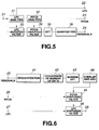
- Fig.5 shows an embodiment of the signal encoder for outputting data to the above signal decoder in further detail.
- Fig.6 shows an embodiment of the signal decoder in further detail.
- the signal encoder finds, as the linear/non-linear prediction residuals of the input signal, the LPC and pitch residuals freed of the LPC components and the pitch components. These LPC and pitch residuals are orthogonal-transformed, for example, DFTed, to produce orthogonal transform coefficient data.
- the signal decoder performs pitch component prediction and LPC prediction, based on LPC and pitch residuals resulting from inverse DFT and synthesizes the speech to produce an output signal.
- the speech signal entering an input terminal 21 is sent to an LPC analysis unit 31 and to an LPC inverted filter 33.
- the LPC analysis unit 31 performs short-term linear prediction of the input signal and outputs an LPC parameter specifying the predicted value to an LPC output terminal 22, a pitch analysis unit 32 and to an LPC inverted filter 33.
- the LPC inverted filter 33 outputs residuals, that is LPC residuals, obtained on subtracting the predicted value of the LPC parameter from the input signal, to a pitch inverted filter 34.
- the pitch analysis unit 32 Based on the LPC parameter, the pitch analysis unit 32 performs auto-correlation analysis to take out the pitch of the input signal to send the pitch data to the pitch output terminal 33 and to the pitch inverted filter 34.
- the pitch inverted filter 34 subtracts the pitch component from the LPC residuals to produce LPC and pitch residuals which are then routed to a DFT unit 35.
- the DFT unit 35 orthogonal-transforms the LPC and pitch residuals.
- DFT is used as an example of the orthogonal transform.
- the amplitude data, produced on DFTing the LPC and pitch residuals, are sent to a quantization unit 36, which then quantizes the amplitude data and sends the quantized amplitude data as transmission data to a residual output terminal 24.
- the number of the amplitude data is N.
- the LPC parameters outputted at an LPC output terminal 22, pitch data outputted at a pitch output terminal 23 and the transmission data outputted at the residual output terminal 24, are recorded on a recording medium or transmitted over a transmission channel so as to be routed to the signal decoder.
- the transmission data, sent from the residual input terminal 25, is dequantized by a dequantizer 41 where it is converted into amplitude data which is routed to a data number converter 42.
- the data number converter 42 converts the number of the amplitude data from N to M by the above-described signal decoding method.
- the M amplitude data are sent to an inverse DFT unit 43.
- the inverse DFT unit 43 transforms the M amplitude data by inverse DFT to find LPC and pitch residuals which are sent to an overlap-and-add unit 44.
- the number of data of the LPC and pitch residuals is M/N times the number of the data of the LPC and pitch residuals outputted by the pitch inverted filter 34.
- the overlap-and-add unit 44 overlap-adds the LPC and pitch residuals between neighboring blocks to produce LPC and pitch residuals containing distortion components in a reduced amount. These residuals are sent to a pitch synthesis filter 45.
- the pitch synthesis filter 45 calculates the pitch from the pitch residual components of the pitch residuals and the LPC and sends the LPC residuals containing the pitch components to an LPC synthesis filter 46.
- LPC synthesis filter Based on the LPC parameters, sent from the LPC synthesis filter performs short-term prediction synthesis, that is LPC synthesis, of speech signals, and sends the resulting speech signal to an output terminal 28.
- the speech signal, sent to the output terminal 28, is the speech signal of which the number of data on the frequency axis is M/N that of the input signal. That is, the speech signals take the playback time M/N times as long as that for the input signal. That is, the playback speed is lowered by a factor of N/M.
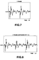
- Figs.7 and 8 show an example of the speech signals processed by the above-described signal encoder and signal decoder.
- Fig.7 shows the signal spectrum on the time axis of the signal prior to orthogonal transform by the signal encoder, that is prior to data number conversion.
- Fig.7 shows the speech signal having 160 samples per frame.
- Fig.8 shows the signal spectrum on the time axis of the signal subsequent to inverse orthogonal transform by the signal decoder, that is subsequent to data number conversion.
- Figs.7 and 8 indicate that, after the number of data of the orthogonal transform coefficients is increased by a factor of 1.5 by data number conversion by the signal decoder, a frame of the spectrum after inverse orthogonal transform has the number of samples which is increased by a factor of 1.5. That is, the spectrum after the inverse orthogonal transform is the speech signal containing 240 samples per frame.
- the present invention is not limited to illustrative embodiments of the signal decoding method and apparatus described above, but may comprise various modifications.
- the method for orthogonal transform of the input signal may also be discrete cosine transform, instead of discrete Fourier transform, for achieving the effect of the present invention.
- the rate of data number conversion M/N may be any arbitrary number instead of 1.5 as described above. If the ratio M/N is larger than 1, the data number is increased thus decreasing the playback speed, whereas, if the ratio M/N is smaller than 1, the number of data is decreased, thus increasing the playback speed.
- the linear/ non-linear analysis performed before conversion to the orthogonal transform coefficient data entering the signal decoder may also be prediction analysis other than short-term prediction and pitch analysis as described above for achieving the same result.
- the above-described signal encoder and signal decoder may be used as a speech codec employed for e.g., a portable communication terminal or a portable telephone shown for example in Figs.9 and 10.
- Fig.9 shows a configuration of a portable terminal employing a speech encoding unit 160 having the configuration shown in Fig.1.
- the speech signal collected by a microphone 161 of Fig.9 is amplified by an amplifier 162 and converted by an A/D converter 163 into a digital signal which is sent to the speech encoding unit 160.
- the speech encoding unit 160 has the configuration shown in Fig.1 in which the digital signal from the A/D converter 163 is entered to an input terminal 101.
- the speech encoding unit performs encoding as explained in connection with Fig.1 so that an output signal from each of the output terminals of Fig.1 is sent as an output signal of the speech encoding unit 160 to a transmission path encoding unit 164 which performs channel decoding.
- An output signal of the transmission path encoding unit 164 is sent to a modulation circuit 165 for modulation and sent via a D/A converter 166 and an RF amplifier 167 to a antenna 168.
- Fig. 10 shows the configuration of the reception side of the portable terminal employing a speech decoding unit 260 configured as shown in Fig.5.
- the speech signal received by an antenna 261 of Fig.10 is amplified by an RF amplifier 262 and sent via an A/D converter 263 to a demodulation circuit 264.
- the resulting demodulated signal from the demodulating unit 264 is sent to a transmission path decoding unit 260 configured as shown for example in Fig.5.
- An output of an output terminal 201 of Fig.5 is sent as a signal from the speech decoding unit 260 to a D/A converter 266.
- An analog speech signal from the D/A converter 266 is sent to a speaker 268.
Abstract
Description
- This invention relates to a method and apparatus for decoding an encoded signal obtained on orthogonal-transforming an input signal.
- There have hitherto been known a variety of encoding methods in which audio signals inclusive of speech signals and acoustic signals are compressed by exploiting statistic properties of the audio signals in the time domain and in the frequency domain and psychoacoustic characteristics of the human being. This encoding method is roughly classified into encoding in the time domain, encoding in the frequency domain and analysis synthesis encoding.
- Meanwhile, in reproducing video signals at a double speed or at a lower speed in, for example, a video apparatus, it has recently been thought to be desirable that the speech signals be reproduced at a constant speed irrespective of the reproducing speed of the video signals. That is, if the speech signals are recorded in a timed relation with the video signals, and if the video signals are reproduced with a one-half speed, the speech signals are also reproduced with a double speed and hence are changed in pitch. Thus it becomes necessary to perform signal compression along time axis taking into account the zero-crossing point for restoring the pitch of the speech signal to the pitch of the original usual reproducing speed.
- With the high-efficiency speech encoding method by the above-mentioned time-axis processing as typified by code excited linear prediction (CELP) encoding, processing of fast modification along the time axis, that is compression along time axis, has been difficult to achieve because of voluminous processing operations involved in a decoder output.
- It is therefore an object of the present invention to provide a signal decoding method and apparatus whereby the speech signal reproducing speed can be controlled easily with a high sound quality without changing the phoneme or pitch.
- In one aspect, the present invention provides a signal decoding method including a step of finding linear or non-linear prediction residuals of an input signal and performing orthogonal transform on the linear or non-linear prediction residuals thus found for entering orthogonal transform coefficient data obtained at a rate of N coefficient data per transform unit, a data number converting step of converting the number of the orthogonal transform coefficient data from N to M and a predictive synthesis step of performing predictive synthesis based on the linear or non-linear prediction residuals obtained, by the data number conversion step.
- With the present data decoding method, the number of orthogonal transform coefficient data, obtained on orthogonal transforming linear/non-linear prediction residuals of the input signal, such as so-called short-term prediction residuals or pitch residuals freed of pitch components, is converted in the data number converting step from N to M, that is the number of data is increased by a factor of M/N. The orthogonal transform coefficient data, converted into the M/N-tuple data by the data number converting step, is inverse orthogonal-transformed in the inverse orthogonal transform step. The inverse orthogonal-transformed linear/non-linear prediction residuals from the inverse transform step are synthesized in the synthesis step to form an output signal, as a result of which the output signal reproducing speed becomes equal to N/M times the reproducing speed in the absence of a data conversion processing for the input signal.
- With the signal decoding method according to the present invention, the number of orthogonal transform coefficient data, supplied after short-term predictive analysis of the input signal and orthogonal transform of the resulting linear/non-linear prediction residuals, may be easily converted into a different number of data. Stated differently, the reproducing speed can be controlled easily.
- In another aspect, the present invention provides a signal decoding apparatus including means for finding linear or non-linear prediction residuals of an input signal and performing orthogonal transform on the linear or non-linear prediction residuals thus found for entering orthogonal transform coefficient data obtained at a rate of N coefficient data per transform unit, data number converting means for converting the number of the orthogonal transform coefficient data from N to M; inverse orthogonal transform means for inverse orthogonal transforming M orthogonal transform coefficient data obtained by the data number conversion means and predictive synthesis means for performing predictive synthesis based on the linear or non-linear prediction residuals obtained by the data number conversion means.
- With the present data decoding apparatus, the data number converting means converts the number of orthogonal transform coefficient data, obtained on orthogonal transforming linear/non-linear prediction residuals of the input signal, such as so-called short-term prediction residuals or pitch residuals freed of pitch components, from N to M, that is increases the number of data by a factor of M/N. The inverse orthogonal transform means inverse orthogonal-transforms the orthogonal transform coefficient data converted into the M/N tuple data obtained by the data number converting means. The synthesis means synthesizes inverse orthogonal-transformed linear/non-linear prediction residuals from the inverse transform step to form an output signal. The result is that the output signal reproducing speed is N/M times the reproducing speed in the absence of a data conversion processing for the input signal.
- With the signal decoding apparatus, the number of orthogonal transform coefficient data, supplied after short-term predictive analysis of the input signal and orthogonal transform of the resulting linear/non-linear prediction residuals, may be easily converted into a different number of data by addition of a simplified structure. Stated differently, the reproducing speed can be controlled easily.
- The present invention will be more clearly understood from the following description, given by way of example only, with reference to the accompanying drawings in which:
- Fig.1 is a block diagram showing an illustrative structure of a signal decoder and a signal encoder configured for formulating transmission data entering the signal decoder.
- Fig.2 is a flowchart for illustrating the detailed operation of the signal decoding method according to the present invention.
- Fig .3 illustrates an example of a data conversion step in the signal decoding method according to the present invention.
- Fig.4 illustrates another example of a data conversion step in the signal decoding method according to the present invention.
- Fig.5 is a block diagram showing a detailed structure of the signal encoder.
- Fig.6 is a block diagram showing a detailed structure of the signal decoder.
- Fig.7 illustrates an example of the speech signal entering the speech encoder.
- Fig.8 illustrates speech signals obtained on processing the speech signals with the signal decoder.
- Fig.9 is a block diagram showing the structure of a transmitter of a portable terminal employing the speech encoder according to the present invention.
- Fig.10 is a block diagram showing the structure of a receiver of a portable terminal employing the speech decoder according to the present invention.
- Referring to the drawings, preferred embodiments of the signal decoding method and apparatus of the present invention will be explained in detail.
- Referring to Fig.1, a signal decoding apparatus (decoder) includes a
data number converter 6 for converting the number of orthogonal transform coefficient data from N to M, an inverseorthogonal transform unit 6 for inverse orthogonal-transforming the M number of the orthogonal transform coefficient data obtained by thedata number converter 5, and a linear predictive coding (LPC)synthesis filter 7 for performing predictive coding based on the short-term prediction residuals obtained by the inverseorthogonal transform unit 6. In the signal decoder, linear/non-linear prediction residuals, for example, short-term prediction residuals, are found for the input signal, and orthogonal-transformed to form orthogonal transform coefficient data at a rate of N coefficient data per transform unit. This N number of the orthogonal transform coefficient data are supplied via a transmissionsignal input terminal 13 to thedata number converter 13 so as to be converted into the M number of coefficient data. - A signal encoding apparatus (encoder) for supplying data to the above-mentioned signal decoder is first explained.
- The speech signal, that is an input signal, entering an
input terminal 11, is filtered by an LPC invertedfilter 1 with, for example, short-term predictive filtering by the linear predictive analysis (LPC) method, for finding short-term prediction residuals, that is LPC residuals. These LPC residuals are orthogonal-transformed by anorthogonal transform unit 2. The orthogonal-transformed speech signals are quantized by aquantizer 3 for conversion into a signal for transmission (transmission signal) which is outputted at asignal output terminal 12. The quantized speech signal is recorded on a recording medium or transmitted using a transmission system, such as an optical fiber. - Before proceeding to description of the signal decoder, the signal decoding method applied to the signal decoder is explained by referring to the flowchart of Fig.2.
- The signal decoding method, has a
step 4, as a data number conversion step for converting the number of the orthogonal transform coefficient data from N to M, a step S6, as an inverse transform step of inverse transforming the M number of the orthogonal transform coefficient data obtained by the data number conversion step, and a step S7, as a synthesis step of performing predictive synthesis based on short-term prediction residuals obtained by the inverse conversion step. In the decoding method, linear/non-linear prediction residuals, for example, short-term prediction residuals, are found for the input signal, and orthogonal-transformed to form orthogonal transform coefficient data at a rate of N coefficient data per transform unit. These orthogonal transform data are supplied to the data number converting step (step S4) where the number of the orthogonal transform data is converted from N to M. - It is assumed that, for discrete Fourier transform (DFT) pairs, obtained on discrete Fourier transforming, as orthogonal transforming, that is x(n), there exist data X(k), where n = 0, ..., N-1 and k = 0, ..., N-1.
- With the signal decoding method, if X'(k) represented by the following equation (1):

- The equation (2) specifies that x'(n) represents conversion of x(n) with a period N and with n-0, ..., N-1.
- If the N number of orthogonal-transformed, that is DFTed, orthogonal transform coefficient data or amplitude data X(k) are expanded/contracted to the number M by pre-set mapping and inverse orthogonal-transformed, that is inverse DFTed, a waveform having a M/N (= 1) tuple duration is obtained. By overlap-adding the resulting waveform, it becomes possible to reproduce the speech having the M/N-tuple time duration on the whole and having the pitch unchanged.
- In the signal decoding method, the above-mentioned transmission signal enters the transmission
signal input terminal 13 at step S1. The transmission signal is dequantized at step S2. Then, at step S3, N orthogonal transform coefficient data, obtained on dequantization, are entered. - At step S4, the amplitude data is cleared to zero and zero-values are added or eliminated to give the target number of data M, that is, the number of data becomes equal to M/N times as large as the number of the original data. The M data thus prepared is termed c(h).
- At step S5, the zero-values at positions of the M zeros satisfying the conditions as later explained are replaced by corresponding amplitude data X(k), as shown by the following equation (3):
 a
a is the maximum integer not exceeding a. The values of the amplitude data X(k) are used unchanged at this time.
- In the equation (3), it is indicated to substitute the post-substitution amplitude data c' for the pre-substitution amplitude data c. As the amplitude data c', the corresponding amplitude data X is employed.
- The above-mentioned condition is explained. It is assumed that M/N = 1.5.
- As a first example, the sample number of a pre-set one of N sample data is set to 0, and the sample number i (i = 0, ..., N-1, that is i = 0, ..., k) specifying the arraying sequence towards the high frequency side is multiplied by M/N, that is 1.5, and the result is half-adjusted (rounded at 0.4 and 0.5 as boundary points). The zero values at the positions corresponding to the results of half-adjustment are replaced by the amplitude data X(k). The zero values at the non-replaced positions are used unchanged.
- As for X(1), 1 × 1.5 = 1.5 which is half-adjusted to 2. Thus, X(1) is substituted for c(2) as c'(2). As for c(1), a zero value is left since there is no associated X(k). As for X(2), 2 × 1.5 = 3 so that X(2) is substituted for c(3). As for X(3), 3 × 1.5 = 4.5 which is half-adjusted to 5, so that X(3) is substituted for c(5). As for c(4), a zero value is left since there is no associated X(k), as in c(1).
- If, as a second example, M/N is 1.5, the position following conversion of, for example, X(1), is 1 × 1.5 = 1.5, which is half-adjusted to 3. X(k) corresponding to 2 is such that k = 2 × (1/1.5) = 4/3.
- Thus, X(k) is over-sampled by 3, as shown in Fig.4a. The over-sampled amplitude data are denoted as Xovs(k).
- That is, Xovs(4/3) is used as c'(2) and substituted for c(2).
- The amplitude data following substitution are shown in Fig.4b.
- As for X(2), since 2 × 1.5 = 3, X(2) is substituted for c(3). As for X(3), 3 × 1.5 = 4.5, which is half-adjusted to 5. As for Xovs(k) substituted for c'(5), since k = 5(1/1.5) = 10/3, it is Xovs(10/3). On the other hand, c(1) and c(4), for example, for which there is no corresponding X(k), that is Xovs(k), remain zero.
- After converting the number of amplitude data from N to M, processing transfers to step S6 where M amplitude data are inverse DFTed and thereby transformed into time-domain signals. At step S7, time-domain signals obtained on inverse DFT processing are used for synthesizing speech signals by LPC synthesis. The resulting speech signals are outputted.
- If M/N = 1.5, the speech signals obtained after data number conversion contain a number of data which is 1.5 times the number of data of the speech signals obtained without data number conversion, so that the playback speed is lowered by a factor equal to a reciprocal of 1.5, that is to 1/1.5 = 0.67. That is, the reproduction is slowed by 1/3 or approximately 33%.
- In consideration of the above-described signal decoding method, the signal decoder is now explained. The operations of the respective portions associated with the respective steps of the signal decoding method are specified by the step numbers.
- In Fig.1, the
dequantizer 4 dequantizes the quantized transmission signal entering the transmission signal input terminal 13 (step S2) to output N amplitude data (step S3). - The
data number converter 5 converts the N amplitude data supplied from thedequantizer 4 to M amplitude data by the above-described signal decoding method (steps S4 and S5) and outputs the M amplitude data to the inverseorthogonal transform unit 6. - The inverse
orthogonal transform unit 6 inverse orthogonal-transforms the M amplitude data at step S6 to find LPC residuals. TheLPC synthesis filter 7 synthesizes the LPC at step S7 based on the LPC residuals to produce speech signals which are sent to anoutput terminal 14. - Fig.5 shows an embodiment of the signal encoder for outputting data to the above signal decoder in further detail. Likewise, Fig.6 shows an embodiment of the signal decoder in further detail.
- In Figs.5 and 6, the signal encoder finds, as the linear/non-linear prediction residuals of the input signal, the LPC and pitch residuals freed of the LPC components and the pitch components. These LPC and pitch residuals are orthogonal-transformed, for example, DFTed, to produce orthogonal transform coefficient data. The signal decoder performs pitch component prediction and LPC prediction, based on LPC and pitch residuals resulting from inverse DFT and synthesizes the speech to produce an output signal.
- Referring to Fig.5, the speech signal entering an input terminal 21 (input signal) is sent to an
LPC analysis unit 31 and to an LPCinverted filter 33. - The
LPC analysis unit 31 performs short-term linear prediction of the input signal and outputs an LPC parameter specifying the predicted value to anLPC output terminal 22, apitch analysis unit 32 and to an LPCinverted filter 33. The LPCinverted filter 33 outputs residuals, that is LPC residuals, obtained on subtracting the predicted value of the LPC parameter from the input signal, to a pitch invertedfilter 34. - Based on the LPC parameter, the
pitch analysis unit 32 performs auto-correlation analysis to take out the pitch of the input signal to send the pitch data to thepitch output terminal 33 and to the pitch invertedfilter 34. The pitch invertedfilter 34 subtracts the pitch component from the LPC residuals to produce LPC and pitch residuals which are then routed to aDFT unit 35. - The
DFT unit 35 orthogonal-transforms the LPC and pitch residuals. In the present embodiment, DFT is used as an example of the orthogonal transform. The amplitude data, produced on DFTing the LPC and pitch residuals, are sent to aquantization unit 36, which then quantizes the amplitude data and sends the quantized amplitude data as transmission data to aresidual output terminal 24. The number of the amplitude data is N. - The LPC parameters outputted at an
LPC output terminal 22, pitch data outputted at a pitch output terminal 23 and the transmission data outputted at theresidual output terminal 24, are recorded on a recording medium or transmitted over a transmission channel so as to be routed to the signal decoder. - In the data decoder, shown in Fig.6, the transmission data, sent from the
residual input terminal 25, is dequantized by adequantizer 41 where it is converted into amplitude data which is routed to adata number converter 42. - The
data number converter 42 converts the number of the amplitude data from N to M by the above-described signal decoding method. The M amplitude data are sent to aninverse DFT unit 43. - The
inverse DFT unit 43 transforms the M amplitude data by inverse DFT to find LPC and pitch residuals which are sent to an overlap-and-addunit 44. The number of data of the LPC and pitch residuals is M/N times the number of the data of the LPC and pitch residuals outputted by the pitch invertedfilter 34. - The overlap-and-add
unit 44 overlap-adds the LPC and pitch residuals between neighboring blocks to produce LPC and pitch residuals containing distortion components in a reduced amount. These residuals are sent to apitch synthesis filter 45. - Based on the pitch data sent from a
pitch input terminal 26, thepitch synthesis filter 45 calculates the pitch from the pitch residual components of the pitch residuals and the LPC and sends the LPC residuals containing the pitch components to anLPC synthesis filter 46. - Based on the LPC parameters, sent from the LPC synthesis filter performs short-term prediction synthesis, that is LPC synthesis, of speech signals, and sends the resulting speech signal to an
output terminal 28. - The speech signal, sent to the
output terminal 28, is the speech signal of which the number of data on the frequency axis is M/N that of the input signal. That is, the speech signals take the playback time M/N times as long as that for the input signal. That is, the playback speed is lowered by a factor of N/M. - Figs.7 and 8 show an example of the speech signals processed by the above-described signal encoder and signal decoder. Thus, Fig.7 shows the signal spectrum on the time axis of the signal prior to orthogonal transform by the signal encoder, that is prior to data number conversion. Fig.7 shows the speech signal having 160 samples per frame. Fig.8 shows the signal spectrum on the time axis of the signal subsequent to inverse orthogonal transform by the signal decoder, that is subsequent to data number conversion.
- Figs.7 and 8 indicate that, after the number of data of the orthogonal transform coefficients is increased by a factor of 1.5 by data number conversion by the signal decoder, a frame of the spectrum after inverse orthogonal transform has the number of samples which is increased by a factor of 1.5. That is, the spectrum after the inverse orthogonal transform is the speech signal containing 240 samples per frame.
- The present invention is not limited to illustrative embodiments of the signal decoding method and apparatus described above, but may comprise various modifications.
- For example, the method for orthogonal transform of the input signal may also be discrete cosine transform, instead of discrete Fourier transform, for achieving the effect of the present invention.
- The rate of data number conversion M/N may be any arbitrary number instead of 1.5 as described above. If the ratio M/N is larger than 1, the data number is increased thus decreasing the playback speed, whereas, if the ratio M/N is smaller than 1, the number of data is decreased, thus increasing the playback speed.
- The linear/ non-linear analysis performed before conversion to the orthogonal transform coefficient data entering the signal decoder may also be prediction analysis other than short-term prediction and pitch analysis as described above for achieving the same result.
- The above-described signal encoder and signal decoder may be used as a speech codec employed for e.g., a portable communication terminal or a portable telephone shown for example in Figs.9 and 10.
- That is, Fig.9 shows a configuration of a portable terminal employing a
speech encoding unit 160 having the configuration shown in Fig.1. The speech signal collected by amicrophone 161 of Fig.9 is amplified by anamplifier 162 and converted by an A/D converter 163 into a digital signal which is sent to thespeech encoding unit 160. Thespeech encoding unit 160 has the configuration shown in Fig.1 in which the digital signal from the A/D converter 163 is entered to an input terminal 101. The speech encoding unit performs encoding as explained in connection with Fig.1 so that an output signal from each of the output terminals of Fig.1 is sent as an output signal of thespeech encoding unit 160 to a transmissionpath encoding unit 164 which performs channel decoding. An output signal of the transmissionpath encoding unit 164 is sent to amodulation circuit 165 for modulation and sent via a D/A converter 166 and anRF amplifier 167 to aantenna 168. - Fig. 10 shows the configuration of the reception side of the portable terminal employing a
speech decoding unit 260 configured as shown in Fig.5. The speech signal received by anantenna 261 of Fig.10 is amplified by anRF amplifier 262 and sent via an A/D converter 263 to ademodulation circuit 264. The resulting demodulated signal from thedemodulating unit 264 is sent to a transmissionpath decoding unit 260 configured as shown for example in Fig.5. An output of an output terminal 201 of Fig.5 is sent as a signal from thespeech decoding unit 260 to a D/A converter 266. An analog speech signal from the D/A converter 266 is sent to aspeaker 268.
Claims (12)
- A signal decoding method comprising:a step of finding linear or non-linear prediction residuals of an input signal and performing orthogonal transform on the linear or non-linear prediction residuals thus found for entering orthogonal transform coefficient data obtained at a rate of N coefficient data per transform unit;a data number converting step of converting the number of said orthogonal transform coefficient data from N to M; anda predictive synthesis step of performing predictive synthesis based on the linear or non-linear prediction residuals obtained by said data number conversion step.
- The signal decoding method as claimed in claim 1 wherein said orthogonal transform coefficient data are data obtained on orthogonal transform of short-term prediction residuals.
- The signal decoding method as claimed in claim 1 or 2 wherein said orthogonal transform coefficient data are pitch residuals obtained on removing pitch components from the input signal.
- The signal decoding method as claimed in claim 1, 2 or 3 wherein said data number converting step includes a data re-arraying step of changing only each sample position without changing the size of said N orthogonal transform coefficient data.
- The signal decoding method as claimed in claim 4 wherein said data re-arraying step is determined by arranging each sample position following said data number conversion in accordance with a sample number obtained on the basis of a value obtained in turn by multiplying the sample number indicating only the original sample position by M/N.
- The signal decoding method as claimed in any preceding claim wherein said orthogonal transform coefficient data are frequency-domain sample data, and wherein said data number conversion step includes an oversampling step of oversampling said frequency-domain sample data and a re-sampling step of re-sampling the frequency-domain sample data obtained by said oversampling step.
- A signal decoding apparatus comprising:means for finding linear or non-linear prediction residuals of an input signal and performing orthogonal transform on the linear or non-linear prediction residuals thus found for entering orthogonal transform coefficient data obtained at a rate of N coefficient data per transform unit;data number converting means for converting the number of said orthogonal transform coefficient data from N to M;inverse orthogonal transform means for inverse orthogonal transforming M orthogonal transform coefficient data obtained by said data number conversion means; andpredictive synthesis means for performing predictive synthesis based on the linear or non-linear prediction residuals obtained by said data number conversion means.
- The signal decoding apparatus as claimed in claim 7 wherein said orthogonal transform coefficient data are data obtained on orthogonal transform of short-term prediction residuals and wherein said prediction synthesis means performs predictive synthesis based on said short-term prediction residuals.
- The signal decoding apparatus as claimed in claim 7 or 8 wherein said orthogonal transform coefficient data are pitch residuals obtained on removing pitch components from the input signal and wherein said predictive synthesis means performs predictive synthesis based on said short-term prediction residuals.
- The signal decoding apparatus as claimed in claim 7, 8 or 9 wherein said data number converting means includes data re-arraying means for changing only each sample position without changing the size of said N orthogonal transform coefficient data.
- The signal decoding apparatus as claimed in claim 10 wherein said data re-arraying means determines each sample position following said data number conversion by arraying said sample position in accordance with a sample number obtained on the basis of a value obtained in turn by multiplying the sample number indicating only the original sample position by M/N.
- A portable radio terminal apparatus comprising:amplifier means for amplifying a reception signal; demodulating means for demodulating the amplified reception signal after A/D conversion thereof;transmission path decoding means for channel decoding the demodulated signal; andspeech decoding means for speech-decoding an output of said transmission path decoding means;said speech decoding means further comprising:a signal decoding apparatus according to any one of claims 7 to 11; andD/A conversion means for D/A converting the speech-decoded signal for producing an analog speech signal.
Applications Claiming Priority (2)
| Application Number | Priority Date | Filing Date | Title |
|---|---|---|---|
| JP279409/95 | 1995-10-26 | ||
| JP7279409A JPH09127995A (en) | 1995-10-26 | 1995-10-26 | Signal decoding method and signal decoder |
Publications (2)
| Publication Number | Publication Date |
|---|---|
| EP0772185A2 true EP0772185A2 (en) | 1997-05-07 |
| EP0772185A3 EP0772185A3 (en) | 1998-08-05 |
Family
ID=17610701
Family Applications (1)
| Application Number | Title | Priority Date | Filing Date |
|---|---|---|---|
| EP96307725A Ceased EP0772185A3 (en) | 1995-10-26 | 1996-10-25 | Speech decoding method and apparatus |
Country Status (4)
| Country | Link |
|---|---|
| US (1) | US5899966A (en) |
| EP (1) | EP0772185A3 (en) |
| JP (1) | JPH09127995A (en) |
| SG (1) | SG43430A1 (en) |
Families Citing this family (12)
| Publication number | Priority date | Publication date | Assignee | Title |
|---|---|---|---|---|
| JP3198996B2 (en) * | 1997-08-26 | 2001-08-13 | 日本電気株式会社 | Image size conversion method for orthogonally coded images |
| JP3541680B2 (en) | 1998-06-15 | 2004-07-14 | 日本電気株式会社 | Audio music signal encoding device and decoding device |
| US6862298B1 (en) | 2000-07-28 | 2005-03-01 | Crystalvoice Communications, Inc. | Adaptive jitter buffer for internet telephony |
| JP3555759B2 (en) | 2001-06-15 | 2004-08-18 | ソニー株式会社 | Display device |
| WO2006026635A2 (en) | 2004-08-30 | 2006-03-09 | Qualcomm Incorporated | Adaptive de-jitter buffer for voice over ip |
| US8085678B2 (en) | 2004-10-13 | 2011-12-27 | Qualcomm Incorporated | Media (voice) playback (de-jitter) buffer adjustments based on air interface |
| CN101061725B (en) * | 2004-11-19 | 2010-08-11 | 松下电器产业株式会社 | Video encoding method, and video decoding method |
| US8355907B2 (en) | 2005-03-11 | 2013-01-15 | Qualcomm Incorporated | Method and apparatus for phase matching frames in vocoders |
| US8155965B2 (en) * | 2005-03-11 | 2012-04-10 | Qualcomm Incorporated | Time warping frames inside the vocoder by modifying the residual |
| JP2008263543A (en) * | 2007-04-13 | 2008-10-30 | Funai Electric Co Ltd | Recording and reproducing device |
| US8321222B2 (en) * | 2007-08-14 | 2012-11-27 | Nuance Communications, Inc. | Synthesis by generation and concatenation of multi-form segments |
| JP4455633B2 (en) * | 2007-09-10 | 2010-04-21 | 株式会社東芝 | Basic frequency pattern generation apparatus, basic frequency pattern generation method and program |
Family Cites Families (16)
| Publication number | Priority date | Publication date | Assignee | Title |
|---|---|---|---|---|
| JPS5650398A (en) * | 1979-10-01 | 1981-05-07 | Hitachi Ltd | Sound synthesizer |
| US4866777A (en) * | 1984-11-09 | 1989-09-12 | Alcatel Usa Corporation | Apparatus for extracting features from a speech signal |
| IT1184023B (en) * | 1985-12-17 | 1987-10-22 | Cselt Centro Studi Lab Telecom | PROCEDURE AND DEVICE FOR CODING AND DECODING THE VOICE SIGNAL BY SUB-BAND ANALYSIS AND VECTORARY QUANTIZATION WITH DYNAMIC ALLOCATION OF THE CODING BITS |
| US4776014A (en) * | 1986-09-02 | 1988-10-04 | General Electric Company | Method for pitch-aligned high-frequency regeneration in RELP vocoders |
| US5179626A (en) * | 1988-04-08 | 1993-01-12 | At&T Bell Laboratories | Harmonic speech coding arrangement where a set of parameters for a continuous magnitude spectrum is determined by a speech analyzer and the parameters are used by a synthesizer to determine a spectrum which is used to determine senusoids for synthesis |
| JPH0782359B2 (en) * | 1989-04-21 | 1995-09-06 | 三菱電機株式会社 | Speech coding apparatus, speech decoding apparatus, and speech coding / decoding apparatus |
| JP2689739B2 (en) * | 1990-03-01 | 1997-12-10 | 日本電気株式会社 | Secret device |
| NL9002308A (en) * | 1990-10-23 | 1992-05-18 | Nederland Ptt | METHOD FOR CODING AND DECODING A SAMPLED ANALOGUE SIGNAL WITH A REPEATING CHARACTER AND AN APPARATUS FOR CODING AND DECODING ACCORDING TO THIS METHOD |
| US5687281A (en) * | 1990-10-23 | 1997-11-11 | Koninklijke Ptt Nederland N.V. | Bark amplitude component coder for a sampled analog signal and decoder for the coded signal |
| US5327518A (en) * | 1991-08-22 | 1994-07-05 | Georgia Tech Research Corporation | Audio analysis/synthesis system |
| US5504833A (en) * | 1991-08-22 | 1996-04-02 | George; E. Bryan | Speech approximation using successive sinusoidal overlap-add models and pitch-scale modifications |
| US5305421A (en) * | 1991-08-28 | 1994-04-19 | Itt Corporation | Low bit rate speech coding system and compression |
| US5349549A (en) * | 1991-09-30 | 1994-09-20 | Sony Corporation | Forward transform processing apparatus and inverse processing apparatus for modified discrete cosine transforms, and method of performing spectral and temporal analyses including simplified forward and inverse orthogonal transform processing |
| US5353374A (en) * | 1992-10-19 | 1994-10-04 | Loral Aerospace Corporation | Low bit rate voice transmission for use in a noisy environment |
| FR2702590B1 (en) * | 1993-03-12 | 1995-04-28 | Dominique Massaloux | Device for digital coding and decoding of speech, method for exploring a pseudo-logarithmic dictionary of LTP delays, and method for LTP analysis. |
| US5504834A (en) * | 1993-05-28 | 1996-04-02 | Motrola, Inc. | Pitch epoch synchronous linear predictive coding vocoder and method |
-
1995
- 1995-10-26 JP JP7279409A patent/JPH09127995A/en not_active Withdrawn
-
1996
- 1996-10-18 SG SG1996010904A patent/SG43430A1/en unknown
- 1996-10-25 EP EP96307725A patent/EP0772185A3/en not_active Ceased
- 1996-10-25 US US08/736,211 patent/US5899966A/en not_active Expired - Fee Related
Non-Patent Citations (1)
| Title |
|---|
| None |
Also Published As
| Publication number | Publication date |
|---|---|
| US5899966A (en) | 1999-05-04 |
| JPH09127995A (en) | 1997-05-16 |
| SG43430A1 (en) | 1997-10-17 |
| EP0772185A3 (en) | 1998-08-05 |
Similar Documents
| Publication | Publication Date | Title |
|---|---|---|
| JP5048697B2 (en) | Encoding device, decoding device, encoding method, decoding method, program, and recording medium | |
| KR100427753B1 (en) | Method and apparatus for reproducing voice signal, method and apparatus for voice decoding, method and apparatus for voice synthesis and portable wireless terminal apparatus | |
| US5299240A (en) | Signal encoding and signal decoding apparatus | |
| EP1160770B2 (en) | Perceptual coding of audio signals using separated irrelevancy reduction and redundancy reduction | |
| JP3926726B2 (en) | Encoding device and decoding device | |
| KR100840439B1 (en) | Audio coding apparatus and audio decoding apparatus | |
| JPH08190764A (en) | Method and device for processing digital signal and recording medium | |
| KR950702762A (en) | Signal encoding apparatus and signal encoding method, signal decoding apparatus and signal decoding method, and recording medium on which signals encoded by such encoding apparatus or method are recorded | |
| US5982817A (en) | Transmission system utilizing different coding principles | |
| EP0772185A2 (en) | Speech decoding method and apparatus | |
| KR20060135699A (en) | Signal decoding apparatus and signal decoding method | |
| KR100352351B1 (en) | Information encoding method and apparatus and Information decoding method and apparatus | |
| WO2005027095A1 (en) | Encoder apparatus and decoder apparatus | |
| KR100750115B1 (en) | Method and apparatus for encoding/decoding audio signal | |
| EP1249837A2 (en) | A method for decompressing a compressed audio signal | |
| JP4308229B2 (en) | Encoding device and decoding device | |
| JP2963710B2 (en) | Method and apparatus for electrical signal coding | |
| JP2958726B2 (en) | Apparatus for coding and decoding a sampled analog signal with repeatability | |
| JPH1083623A (en) | Signal recording method, signal recorder, recording medium and signal processing method | |
| JP3827720B2 (en) | Transmission system using differential coding principle | |
| JPH04249300A (en) | Method and device for voice encoding and decoding | |
| JP2001083995A (en) | Sub band encoding/decoding method | |
| JPH07334194A (en) | Method and device for encoding/decoding voice | |
| JP3504485B2 (en) | Tone encoding device, tone decoding device, tone encoding / decoding device, and program storage medium | |
| JPH07221650A (en) | Method and device for encoding information and method and device for decoding information |
Legal Events
| Date | Code | Title | Description |
|---|---|---|---|
| PUAI | Public reference made under article 153(3) epc to a published international application that has entered the european phase |
Free format text: ORIGINAL CODE: 0009012 |
|
| AK | Designated contracting states |
Kind code of ref document: A2 Designated state(s): AT DE FR GB NL |
|
| PUAL | Search report despatched |
Free format text: ORIGINAL CODE: 0009013 |
|
| AK | Designated contracting states |
Kind code of ref document: A3 Designated state(s): AT DE FR GB NL |
|
| 17P | Request for examination filed |
Effective date: 19990111 |
|
| 17Q | First examination report despatched |
Effective date: 20010212 |
|
| GRAG | Despatch of communication of intention to grant |
Free format text: ORIGINAL CODE: EPIDOS AGRA |
|
| RIC1 | Information provided on ipc code assigned before grant |
Free format text: 7G 10L 19/02 A, 7G 10L 19/12 B, 7G 10L 21/04 B |
|
| STAA | Information on the status of an ep patent application or granted ep patent |
Free format text: STATUS: THE APPLICATION HAS BEEN REFUSED |
|
| 18R | Application refused |
Effective date: 20020725 |