EP0772166A1 - A system for monitoring a multiplicity of doors - Google Patents
A system for monitoring a multiplicity of doors Download PDFInfo
- Publication number
- EP0772166A1 EP0772166A1 EP95202914A EP95202914A EP0772166A1 EP 0772166 A1 EP0772166 A1 EP 0772166A1 EP 95202914 A EP95202914 A EP 95202914A EP 95202914 A EP95202914 A EP 95202914A EP 0772166 A1 EP0772166 A1 EP 0772166A1
- Authority
- EP
- European Patent Office
- Prior art keywords
- doors
- transceiver
- multiplicity
- message
- dcu
- Prior art date
- Legal status (The legal status is an assumption and is not a legal conclusion. Google has not performed a legal analysis and makes no representation as to the accuracy of the status listed.)
- Granted
Links
Images


Classifications
-
- E—FIXED CONSTRUCTIONS
- E05—LOCKS; KEYS; WINDOW OR DOOR FITTINGS; SAFES
- E05G—SAFES OR STRONG-ROOMS FOR VALUABLES; BANK PROTECTION DEVICES; SAFETY TRANSACTION PARTITIONS
- E05G1/00—Safes or strong-rooms for valuables
- E05G1/06—Safes or strong-rooms for valuables having provision for multiple compartments
- E05G1/08—Safes or strong-rooms for valuables having provision for multiple compartments secured individually
-
- G—PHYSICS
- G07—CHECKING-DEVICES
- G07F—COIN-FREED OR LIKE APPARATUS
- G07F17/00—Coin-freed apparatus for hiring articles; Coin-freed facilities or services
- G07F17/10—Coin-freed apparatus for hiring articles; Coin-freed facilities or services for means for safe-keeping of property, left temporarily, e.g. by fastening the property
- G07F17/12—Coin-freed apparatus for hiring articles; Coin-freed facilities or services for means for safe-keeping of property, left temporarily, e.g. by fastening the property comprising lockable containers, e.g. for accepting clothes to be cleaned
Definitions
- the present invention relates to monitoring apparatus generally and more particularly to electro-optical monitoring apparatus.
- the present invention seeks to provide an improved system for monitoring which is particularly useful for monitoring the opening and closing of a plurality of doors arranged in a generally planar array.
- a system for monitoring a multiplicity of doors including at least one optical transceiver mounted on each of the multiplicity of doors and communications apparatus for communicating with each of the multiplicity of doors thereby to verify their position.
- the communications apparatus is operative to communicate with at least some of the optical transceivers via others of the optical transceivers.
- the communications apparatus is operative to communicate with the optical transceivers on the multiplicity of doors via a plurality of alternative communications pathways.
- each transceiver includes, for at least some of the multiplicity of doors, a plurality of optical transmitters and receivers operative in a plurality of different directions.
- Each transceiver is preferably autonomously powered.
- each transceiver includes at least one light emitting diode and light sensor.
- each transceiver includes a microprocessor.
- each transceiver is operative to provide an indication of an open door or inoperative transceiver downstream thereof in a communications chain.
- the communications apparatus includes a personal computer and communicates with the transceivers via at least two communications interfaces.
- the plurality of doors are doors of a bank of safe deposit boxes.
- system also includes apparatus for logging door openings and inoperative transceivers on a time based log.
- Fig. 1 is a simplified pictorial illustration of a system for monitoring a plurality of doors, constructed and operative in accordance with a preferred embodiment of the present invention.
- the system is here shown in the context of monitoring a bank of safe deposit boxes, which is a preferred application. It is to be appreciated, however, that the invention is not limited to this or any other particular application.
- the bank of safe deposit boxes is arranged in a plurality of vertical columns 22, labeled A - G, and a plurality of horizontal rows 24, labeled 1 - 8. It is to be appreciated that any suitable number of boxes may be monitored in accordance with a preferred embodiment of the present invention.
- the system includes a multiplicity of door monitoring units 26, hereinafter termed “DCU”s or transceivers, each of which is mounted on the door of a separate box.
- DCU door monitoring units
- ECU edge monitoring units
- a plurality of ECUs 28 are arranged along the bottom of the bank of boxes 20, one ECU being arranged in registration with one column of DCUs 26, such that, for example, the ECU labeled A communicates with the DCUs in column A and so on.
- the ECUs could be arranged along a vertical edge of the bank 20.
- the ECUs are arranged for communication and are referred to collectively as a common block, hereinafter termed "ECB”.
- a system control unit 32 hereinafter termed “SCU” controls the ECUs 30 and may in turn be controlled by a system manager 34, which may be embodied in software and be operated by an operator using a conventional personal computer.
- each ECU 28 typically comprises an optical transceiver 40, preferably an LED 42 and a light sensor 44, such as a Schmitt photodetector.
- the optical transceiver pair 40 communicates with a controller 46, which in turn communicates along the ECB block 30 and with the SCU 32.
- Each DCU preferably includes four optical transceivers 40, disposed along each edge thereof, communicating with a controller 50.
- the optical transceiver pairs 40 of each DCU 26 are arranged in opposite registration with adjacent corresponding optical transceiver pairs 40 on adjacent DCUs 26 and, where appropriate, with an optical transceiver pair 40 of an adjacent ECU 28, such that serial communication of all adjacent DCUs with each other and with adjacent ECUs 28 is provided, as will be described hereinafter in greater detail.
- the four optical transceiver pairs 40 are designated as follows: Two vertically directed pairs, identified by reference numerals 41 and 43 respectively are termed UPPER LINK and LOWER LINK. Two horizontally directed pairs, identified by reference numerals 45 and 47 respectively are termed RIGHT LINK and LEFT LINK.
- transceiver pairs on the ECUs and SCUs are also labeled in accordance with the above convention.
- the ECUs, SCUs and DCUs may include the same hardware platform.
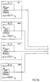
- the RIGHT LINK and LEFT LINK of adjacent transceivers may communicate either by wire, as illustrated in Fig. 2, or optically.
- Controller 50 is delineated by dashed lines and includes a CPU 52 and an associated RAM 54 and ROM 56.
- the CPU 52 communicates via an I/O bus with respective transmit and receive registers 58 and 60.
- Register 58 communicates via a LED buffer 62 with four LEDS 64, 66, 68 and 70, each directed in a different direction.
- Register 60 communicates via a sensor buffer 72 with four sensors 74, 76, 78 and 80, each directed in a different direction.
- a power module 82 provides power to the controller 50 and preferably includes an autonomous power source such as solar cells 84 or an RF energy receiver and rectifier assembly 86.
- the autonomous power source provides electrical power to a power supply 88, which converts the electrical power to voltages appropriate for use by the various elements of the DCU 26.
- Controller 46 includes a CPU 102 and an associated RAM 104 and ROM 106.
- the CPU 102 communicates via an I/O bus with respective transmit and receive registers 108, 134, 110 and 130.
- Register 108 communicates via a LED buffer 112 with an LED 114.
- Register 110 communicates via a sensor buffer 116 with a sensor 118.
- Register 130 receives, via a buffer 132, information from an adjacent ECU, if present.
- Register 134 transmits via a buffer 136 to an adjacent ECU, if present.
- serial input 103 and serial output 105 from the CPU 102 provide communication with the SCU 32.
- FIG. 5 A schematic illustration of a preferred embodiment of DCU, circuitry appears in Fig. 5. The schematic illustration is believed to be self explanatory, accordingly, no additional description thereof is believed to be necessary. Identical circuitry is employed also for the ECU and SCU circuitry. A listing of software resident in the microcontroller of Fig. 5 appears in Appendix A, for DCU, ECU and SCU functionalities.
- the system manager is operative following initialization to confirm that no door is open and that no door has been authorized to be opened.
- the system manager is then prepared to deal with any one of three events: a timer event, a user input, receipt of a message from the SCU 32 (Fig. 1). Following occurrence of an event, the system manager returns to an idle state.
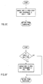
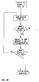
- Fig. 6B The operation of the system manager upon occurrence of a timer event is illustrated in Fig. 6B. If an excessive time has passed since the last message, a report to that effect is logged and an alarm is sounded. Otherwise, a request is transmitted to the SCU 32 to perform a block poll, as will be described hereinbelow.
- Figs. 6F, 6D, 6E and 6G The subroutines dedicated to the above messages NBIO, LBIO, RBIO and ENDP are illustrated in respective Figs. 6F, 6D, 6E and 6G.
- Each of the subroutines shown in Figs. 6F, 6D and 6E employ a subroutine which is explained hereinbelow with reference to Fig. 6I.
- the subject matter of Figs. 6F, 6D, 6E and 6G is not believed to require further explanation.
- Fig. 6H The operation of the system manager upon receipt of an input from a user is illustrated in Fig. 6H.
- a user indicates a single door which he is authorized to open and normally provides the requisite identification to a security operative.
- the system manager notes in a register that the indicated door is authorized to be opened.
- the system manager notes in a register that the indicated door is no longer authorized to open.
- the system as described herein is configured to only permit one authorized box opening at any given time. Alternatively, the system could be configured to permit more than one authorized box opening at a given time.
- Fig. 6I The operation of the system manager upon reception of a message from a SCU, indicating the open status of a door is illustrated in Fig. 6I.
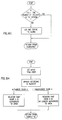
- the system checks to determine whether the door which is indicated to be open is authorized to be open. If not, an alarm is sounded. In any event, the open status of the door is logged by column and row numbers.
- Figs. 7A and 7B illustrate the operation of SCU circuitry 32.
- the SCU circuitry awaits a poll command from the system manager 34. Upon receipt of the poll command it conducts polling the status of block 20 (Fig. 1).
- the task of the SCU is to transmit a poll instruction message to a first ECU in response to a poll system instruction from the system manager 34 (Fig. 1) and to then receive the various return messages therefrom. These messages are then retransmitted by the SCU to the system manager 34.
- the polling of block 20 is achieved by transmitting a poll message to a first ECU and then awaiting a message from the ECU. If the message is properly received, it is echoed to the system manager 34. If the message is not properly received, the SCU exits the subroutine of Fig. 7B. The subroutine is operative until an ENDP message is received and echoed to the system manager 34.
- FIG. 8A, 8B, 8C, 8D, 8E and 8F illustrating the operation of the system manager of Figs. 1-5.
- the ECU waits for a wake-up signal and upon receipt thereof handles a start-bit from a LINK HX.
- the ECU circuitry upon receipt of the message along LINK HX, and if the message is successfully received, the ECU circuitry deals with the following types of messages received from LINK HX:
- the ECU upon receipt of an NBIO, RBIO or LBIO message, the ECU retransmits the same message with the received column and row indices (COL, ROW) changed to (COL+1,ROW) to LINK 1 - HX, i.e. the opposite link on the same transceiver.
- the ECU upon receipt of an ENDP message from LINK HX, the ECU performs a DCU column poll and transmits an ENDP message with the received (COL, ROW) indication changed to (COL+1,ROW) to link 1 - HX, i.e. the opposite link.
- the ECU upon receipt of a POLL message from LINK HX, the ECU also transmits a poll message to LINK 1 - HX. If the transmission is not successful it performs a DCU column poll and transmits the result to link 1 - HX. It also transmits a ENDP message with a column indication 0 to link 1 - HX.
- the ECU transmits a POLL message to the most adjacent DCU (transceiver). If the transmission is not successful, the ECU transmits an NBIO message with indices (0,0) to LINK HX for ultimate transmittal to the SCU 32 and the system manager 34.
- the ECU awaits a message from the adjacent DCU. If such a message is not received successfully, the ECU exits the subroutine. If a message is successfully received from the adjacent DCU, it is dealt with depending on the type of message, i.e. LBIO, RBIO or NBIO.
- the ECU transmits a message of the same type to a link HX for ultimate transmittal to the SCU 32 and the system manager 34.
- the index of the message is a column index 0 and a row index equal to the received index incremented by +1.
- the ECU In the event of receipt of RBIO and LBIO messages, the ECU remains in the subroutine awaiting further messages. If an NBIO message is received, the ECU exits the subroutine.
- Figs. 9A, 9B, 9C, 9D, 9E, 9F, 9G, 9H, 9I and 9J are flow charts illustrating the operation of the DCU circuitry of Figs. 1 - 5.
- the DCU upon supply of power to the DCU circuitry and initialization thereof, the DCU remains in a dormant state until it is awakened up by a received signal.
- the received signal may come from a source which is vertically separated from the DCU or a source which is horizontally separated from the DCU. Once the received signal has been dealt with, the DCU returns to its dormant state.
- the DCU retransmits the communication back to the source. If, however, as seen in Fig. 9C, the signal is received from a source that is vertically separated from the DCU, the DCU checks if the message has been correctly received. If so, each message is handled separately and when it has been handled, the DCU returns to its dormant state.
- Fig. 9D illustrates handling of a POLL message from a LINK VX and indicates that the received POLL message is retransmitted to an opposite link, LINK 1 - VX. If the transmission is not successful, the DCU transmits the status of its right and left neighbors back to link VX and also transmits an NBIO message with index 0 to link VX.
- Fig. 9E Transmission of the status of the right and left neighbors is illustrated in Fig. 9E. An inquiry is made as to whether the right neighbor door is open. If so, an RBIO message is transmitted to link VX with index 0. An inquiry is made if the left neighbor door is open. If so, an LBIO message is transmitted to link VX with index 0.
- Reading status of a neighbor is illustrated in Fig. 9F and includes the steps of communicating with a neighboring DCU. If the communication is successful, an indication is provided that the neighboring door is closed. If the communication is not successful, an indication is provided that the neighboring door is open.
- Handling of an NBIO message is illustrated in Fig. 9G and includes transmitting the status of the right and left neighbors as described hereinabove and afterwards transmitting an NBIO message with an ROW index incremented by +1 to the opposite link 1 - VX.
- Handling of an RBIO message is illustrated in Fig. 9H and includes transmitting an RBIO message with a ROW index incremented by +1 to the opposite link 1 - VX.
- Handling of an LBIO message is illustrated in Fig. 9I and includes transmitting an LBIO message with an ROW index incremented by +1 to the opposite link 1 - VX.
Landscapes
- Physics & Mathematics (AREA)
- General Physics & Mathematics (AREA)
- Power-Operated Mechanisms For Wings (AREA)
- Burglar Alarm Systems (AREA)
- Small-Scale Networks (AREA)
- Selective Calling Equipment (AREA)
- Closed-Circuit Television Systems (AREA)
- Special Wing (AREA)
Abstract
Description
- The present invention relates to monitoring apparatus generally and more particularly to electro-optical monitoring apparatus.
- There exist in the patent literature a variety of patents which deal with monitoring the opening and closing of a door. The following U.S. patents are representative of the prior art: 3,816,745; 3,875,403; 3,987,428; 4,266,124; 4,319,332; 4,324,977; 4,390,867; 4,583,082; 4,650,990; 4,742,337; 4,812,810; 4,841,283; 4,903,009; 4,965,551; 5,015,840; 5,063,288; 5,111,184; 5,134,386 and 5,138,299.
- The present invention seeks to provide an improved system for monitoring which is particularly useful for monitoring the opening and closing of a plurality of doors arranged in a generally planar array.
- There is thus provided in accordance with a preferred embodiment of the present invention a system for monitoring a multiplicity of doors including at least one optical transceiver mounted on each of the multiplicity of doors and communications apparatus for communicating with each of the multiplicity of doors thereby to verify their position.
- Preferably the communications apparatus is operative to communicate with at least some of the optical transceivers via others of the optical transceivers.
- In accordance with a preferred embodiment of the present invention the communications apparatus is operative to communicate with the optical transceivers on the multiplicity of doors via a plurality of alternative communications pathways.
- Preferably each transceiver includes, for at least some of the multiplicity of doors, a plurality of optical transmitters and receivers operative in a plurality of different directions. Each transceiver is preferably autonomously powered.
- In accordance with a preferred embodiment of the present invention each transceiver includes at least one light emitting diode and light sensor. Preferably each transceiver includes a microprocessor.
- Additionally in accordance with a preferred embodiment of the present invention, each transceiver is operative to provide an indication of an open door or inoperative transceiver downstream thereof in a communications chain.
- Preferably, the communications apparatus includes a personal computer and communicates with the transceivers via at least two communications interfaces.
- In accordance with a preferred embodiment of the present invention, the plurality of doors are doors of a bank of safe deposit boxes.
- Additionally in accordance with a preferred embodiment of the present invention the system also includes apparatus for logging door openings and inoperative transceivers on a time based log.
- The present invention will be more fully understood and appreciated from the following detailed description, taken in conjunction with the drawings in which:
- Fig. 1 is a pictorial illustration of a monitoring system constructed and operative in accordance with a preferred embodiment of the present invention;
- Fig. 2 is a simplified partially pictorial, partially block diagram illustration of part of the system of Fig. 1;
- Fig. 3 is a simplified block diagram of DCU circuitry mounted on each door being monitored in the system;
- Fig. 4 is a simplified block diagram of ECU circuitry forming part of the apparatus of Figs. 1 and 2;
- Fig. 5 is an electrical schematic illustration of electrical circuitry employed in a preferred embodiment of the ECU, DCU and SCU circuitry;
- Figs. 6A, 6B, 6C, 6D, 6E, 6F, 6G, 6H and 6I are flow charts illustrating the operation of the system manager of Figs. 1 and 2;
- Figs. 7A and 7B are flow charts illustrating the operation of the SCU circuitry of Figs. 1 - 5;
- Figs. 8A, 8B, 8C, 8D, 8E and 8F are flow charts illustrating the operation of the ECU circuitry of Figs. 1 - 5; and
- Figs. 9A, 9B, 9C, 9D, 9E, 9F, 9G, 9H and 9I are flow charts illustrating the operation of the DCU circuitry of Figs. 1 - 5.
-
- Appendix A is a software listing in Intel Intellec - 8 HEX dump format of software resident in the DCU, ECU and SCU circuitry;
- Appendix B is a listing of a sequence of events which characterizes operation of an embodiment of the invention including four DCUs in four different operational cases.
- Reference is now made to Fig. 1, which is a simplified pictorial illustration of a system for monitoring a plurality of doors, constructed and operative in accordance with a preferred embodiment of the present invention. The system is here shown in the context of monitoring a bank of safe deposit boxes, which is a preferred application. It is to be appreciated, however, that the invention is not limited to this or any other particular application.
- For the purpose of explanation, the bank of safe deposit boxes, indicated generally by
reference numeral 20, is arranged in a plurality ofvertical columns 22, labeled A - G, and a plurality ofhorizontal rows 24, labeled 1 - 8. It is to be appreciated that any suitable number of boxes may be monitored in accordance with a preferred embodiment of the present invention. - In accordance with a preferred embodiment of the present invention, the system includes a multiplicity of
door monitoring units 26, hereinafter termed "DCU"s or transceivers, each of which is mounted on the door of a separate box. Communicating with thedoor monitoring units 26 are a plurality ofedge monitoring units 28, hereinafter termed "ECU"s. - In the illustrated embodiment, a plurality of
ECUs 28 are arranged along the bottom of the bank ofboxes 20, one ECU being arranged in registration with one column ofDCUs 26, such that, for example, the ECU labeled A communicates with the DCUs in column A and so on. Alternatively, the ECUs could be arranged along a vertical edge of thebank 20. - The ECUs are arranged for communication and are referred to collectively as a common block, hereinafter termed "ECB". A
system control unit 32, hereinafter termed "SCU" controls theECUs 30 and may in turn be controlled by asystem manager 34, which may be embodied in software and be operated by an operator using a conventional personal computer. - Reference is now made to Fig. 2, which illustrates a representative part of the system of Fig. 1. It is seen that each
ECU 28 typically comprises anoptical transceiver 40, preferably anLED 42 and alight sensor 44, such as a Schmitt photodetector. Theoptical transceiver pair 40 communicates with acontroller 46, which in turn communicates along theECB block 30 and with theSCU 32. - Each DCU preferably includes four
optical transceivers 40, disposed along each edge thereof, communicating with acontroller 50. Theoptical transceiver pairs 40 of eachDCU 26 are arranged in opposite registration with adjacent correspondingoptical transceiver pairs 40 onadjacent DCUs 26 and, where appropriate, with anoptical transceiver pair 40 of anadjacent ECU 28, such that serial communication of all adjacent DCUs with each other and withadjacent ECUs 28 is provided, as will be described hereinafter in greater detail. - The four
optical transceiver pairs 40 are designated as follows: Two vertically directed pairs, identified byreference numerals reference numerals - For the sake of convenience in notation, correspondingly positioned transceiver pairs on the ECUs and SCUs are also labeled in accordance with the above convention. In practice, for engineering and manufacturing simplicity, the ECUs, SCUs and DCUs may include the same hardware platform. In the ECUs, the RIGHT LINK and LEFT LINK of adjacent transceivers may communicate either by wire, as illustrated in Fig. 2, or optically.
- Reference is now made to Fig. 3, which is a simplified block diagram illustration of the
DCU 26.Controller 50 is delineated by dashed lines and includes aCPU 52 and an associatedRAM 54 andROM 56. TheCPU 52 communicates via an I/O bus with respective transmit and receiveregisters LED buffer 62 with fourLEDS sensor buffer 72 with foursensors - A
power module 82 provides power to thecontroller 50 and preferably includes an autonomous power source such assolar cells 84 or an RF energy receiver andrectifier assembly 86. The autonomous power source provides electrical power to apower supply 88, which converts the electrical power to voltages appropriate for use by the various elements of theDCU 26. - Reference is now made to Fig. 4, which is a simplified block diagram illustration of the
ECU 28.Controller 46 includes aCPU 102 and an associatedRAM 104 andROM 106. TheCPU 102 communicates via an I/O bus with respective transmit and receiveregisters Register 108 communicates via aLED buffer 112 with anLED 114.Register 110 communicates via asensor buffer 116 with asensor 118. -
Register 130 receives, via abuffer 132, information from an adjacent ECU, if present.Register 134 transmits via abuffer 136 to an adjacent ECU, if present. - The
serial input 103 andserial output 105 from theCPU 102 provide communication with theSCU 32. - A schematic illustration of a preferred embodiment of DCU, circuitry appears in Fig. 5. The schematic illustration is believed to be self explanatory, accordingly, no additional description thereof is believed to be necessary. Identical circuitry is employed also for the ECU and SCU circuitry. A listing of software resident in the microcontroller of Fig. 5 appears in Appendix A, for DCU, ECU and SCU functionalities.
- The operation of the apparatus of Figs. 1 - 5 will now be explained with particular reference to Figs. 6A - 6I.
- As illustrated in Fig. 6A, in accordance with a preferred embodiment of the invention, the system manager is operative following initialization to confirm that no door is open and that no door has been authorized to be opened. The system manager is then prepared to deal with any one of three events: a timer event, a user input, receipt of a message from the SCU 32 (Fig. 1). Following occurrence of an event, the system manager returns to an idle state.
- The operation of the system manager upon occurrence of a timer event is illustrated in Fig. 6B. If an excessive time has passed since the last message, a report to that effect is logged and an alarm is sounded. Otherwise, a request is transmitted to the
SCU 32 to perform a block poll, as will be described hereinbelow. - The operation of the system manager upon receipt of a message from the SCU is illustrated in Fig. 6C. Four types of messages are dealt with as will be described hereinbelow:
- NBIO - NO BOX IS OPEN
- RBIO - RIGHT BOX IS OPEN
- LBIO - LEFT BOX IS OPEN
- ENDP - END OF POLL
- The subroutines dedicated to the above messages NBIO, LBIO, RBIO and ENDP are illustrated in respective Figs. 6F, 6D, 6E and 6G. Each of the subroutines shown in Figs. 6F, 6D and 6E employ a subroutine which is explained hereinbelow with reference to Fig. 6I. Other than this subroutine, the subject matter of Figs. 6F, 6D, 6E and 6G is not believed to require further explanation.
- The operation of the system manager upon receipt of an input from a user is illustrated in Fig. 6H. A user indicates a single door which he is authorized to open and normally provides the requisite identification to a security operative. The system manager notes in a register that the indicated door is authorized to be opened. When the user has completed accessing a given vault via the door, the system manager notes in a register that the indicated door is no longer authorized to open. The system as described herein is configured to only permit one authorized box opening at any given time. Alternatively, the system could be configured to permit more than one authorized box opening at a given time.
- The operation of the system manager upon reception of a message from a SCU, indicating the open status of a door is illustrated in Fig. 6I. The system checks to determine whether the door which is indicated to be open is authorized to be open. If not, an alarm is sounded. In any event, the open status of the door is logged by column and row numbers.
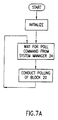
- Reference is now made to Figs. 7A and 7B which illustrate the operation of
SCU circuitry 32. Following initialization, the SCU circuitry awaits a poll command from thesystem manager 34. Upon receipt of the poll command it conducts polling the status of block 20 (Fig. 1). - Generally speaking, the task of the SCU is to transmit a poll instruction message to a first ECU in response to a poll system instruction from the system manager 34 (Fig. 1) and to then receive the various return messages therefrom. These messages are then retransmitted by the SCU to the
system manager 34. - As illustrated in Fig. 7B, the polling of
block 20 is achieved by transmitting a poll message to a first ECU and then awaiting a message from the ECU. If the message is properly received, it is echoed to thesystem manager 34. If the message is not properly received, the SCU exits the subroutine of Fig. 7B. The subroutine is operative until an ENDP message is received and echoed to thesystem manager 34. - Reference is now made to Figs. 8A, 8B, 8C, 8D, 8E and 8F illustrating the operation of the system manager of Figs. 1-5.
- The following notation will be employed in the discusion which follows:
- LINK HX - one of the two horizontal links on a transceiver (DCU, ECU or SCU).
- LINK 1 - HX - the other one of the two horizontal links on the transceiver (DCU, ECU or SCU).
- LINK VX - one of the two vertical links on a transceiver (DCU, ECU or SCU).
- LINK 1 - VX - the other one of the two vertical links on the transceiver (DCU, ECU or SCU).
- As seen in Fig. 8A, following initialization, the ECU waits for a wake-up signal and upon receipt thereof handles a start-bit from a LINK HX.
- As illustrated in Fig. 8B, upon receipt of the message along LINK HX, and if the message is successfully received, the ECU circuitry deals with the following types of messages received from LINK HX:
- NBIO - NO BOX IS OPEN
- RBIO - RIGHT BOX IS OPEN
- LBIO - LEFT BOX IS OPEN
- ENDP - END OF POLL
- POLL - POLL INSTRUCTION
- As illustrated in Fig. 8C, upon receipt of an NBIO, RBIO or LBIO message, the ECU retransmits the same message with the received column and row indices (COL, ROW) changed to (COL+1,ROW) to LINK 1 - HX, i.e. the opposite link on the same transceiver.
- As illustrated in Fig. 8D, upon receipt of an ENDP message from LINK HX, the ECU performs a DCU column poll and transmits an ENDP message with the received (COL, ROW) indication changed to (COL+1,ROW) to link 1 - HX, i.e. the opposite link.
- As illustrated in Fig. 8E, upon receipt of a POLL message from LINK HX, the ECU also transmits a poll message to LINK 1 - HX. If the transmission is not successful it performs a DCU column poll and transmits the result to link 1 - HX. It also transmits a ENDP message with a
column indication 0 to link 1 - HX. - As seen in Fig. 8F, the ECU transmits a POLL message to the most adjacent DCU (transceiver). If the transmission is not successful, the ECU transmits an NBIO message with indices (0,0) to LINK HX for ultimate transmittal to the
SCU 32 and thesystem manager 34. - If the transmission is successful, the ECU awaits a message from the adjacent DCU. If such a message is not received successfully, the ECU exits the subroutine. If a message is successfully received from the adjacent DCU, it is dealt with depending on the type of message, i.e. LBIO, RBIO or NBIO.
- In the event of receipt of any of the above three types of messages the ECU transmits a message of the same type to a link HX for ultimate transmittal to the
SCU 32 and thesystem manager 34. The index of the message is acolumn index 0 and a row index equal to the received index incremented by +1. - In the event of receipt of RBIO and LBIO messages, the ECU remains in the subroutine awaiting further messages. If an NBIO message is received, the ECU exits the subroutine.
- Reference is now made to Figs. 9A, 9B, 9C, 9D, 9E, 9F, 9G, 9H, 9I and 9J which are flow charts illustrating the operation of the DCU circuitry of Figs. 1 - 5.
- As illustrated in Fig. 9A, upon supply of power to the DCU circuitry and initialization thereof, the DCU remains in a dormant state until it is awakened up by a received signal. The received signal may come from a source which is vertically separated from the DCU or a source which is horizontally separated from the DCU. Once the received signal has been dealt with, the DCU returns to its dormant state.
- As seen in Fig. 9B, if the signal is received from a source that is horizontally separated from the DCU, the DCU retransmits the communication back to the source. If, however, as seen in Fig. 9C, the signal is received from a source that is vertically separated from the DCU, the DCU checks if the message has been correctly received. If so, each message is handled separately and when it has been handled, the DCU returns to its dormant state.
- The description of the handling of the various types of messages is provided with reference to the drawings in accordance with the following table:
MESSAGE TYPE FIGURE POLL Fig. 9D NBIO Fig. 9G RBIO Fig. 9H LBIO Fig. 9I - Fig. 9D illustrates handling of a POLL message from a LINK VX and indicates that the received POLL message is retransmitted to an opposite link, LINK 1 - VX. If the transmission is not successful, the DCU transmits the status of its right and left neighbors back to link VX and also transmits an NBIO message with
index 0 to link VX. - Transmission of the status of the right and left neighbors is illustrated in Fig. 9E. An inquiry is made as to whether the right neighbor door is open. If so, an RBIO message is transmitted to link VX with
index 0. An inquiry is made if the left neighbor door is open. If so, an LBIO message is transmitted to link VX withindex 0. - Reading status of a neighbor is illustrated in Fig. 9F and includes the steps of communicating with a neighboring DCU. If the communication is successful, an indication is provided that the neighboring door is closed. If the communication is not successful, an indication is provided that the neighboring door is open.
- Handling of an NBIO message is illustrated in Fig. 9G and includes transmitting the status of the right and left neighbors as described hereinabove and afterwards transmitting an NBIO message with an ROW index incremented by +1 to the opposite link 1 - VX.
- Handling of an RBIO message is illustrated in Fig. 9H and includes transmitting an RBIO message with a ROW index incremented by +1 to the opposite link 1 - VX.
- Handling of an LBIO message is illustrated in Fig. 9I and includes transmitting an LBIO message with an ROW index incremented by +1 to the opposite link 1 - VX.
- It will be appreciated by persons skilled in the art that the present invention is not limited by what has been particularly shown and described hereinabove. Rather the scope of the present invention is defined only by the claims which follow:


Claims (10)
- A system for monitoring a multiplicity of doors comprising:at least one optical transceiver mounted on each of the multiplicity of doors; andcommunication apparatus for communicating with said at least one optical transceiver mounted on each of the multiplicity of doors thereby toverify their position, said communication appratus being operative to communicate with the at least one optical transceiver on each of said multiplicity od doors via plural alternative serial communications pathways, at least one of said plural pathways extending via optical transceviers mounted on a plurality of different doors.
- A system according to claim 1 and wherein said at least one transceiver comprises, for at least some of said multiplicity of doors, a plurality of optical transmitters and receivers operative in a plurality of different directions.
- A system according to claim 1 and wherein said at least one transceiver on each of said plurality of doors is autonomously powered.
- A system according to claim1 and wherein said at least one transceiver comprises at least one light emitting diode and light sensor.
- A system according to claim 1 and wherein said at least one transceiver comprises a microprocessor.
- A system according to claim 1 and wherein said at least one transceiver is operative to provide an indication of an open door or inoperative transceiver downstream thereof in a communications chain.
- A system according to claim 1 and wherein said communications apparatus comprises a personal computer.
- A system according to claim 1 and wherein said communications apparatus communicates with said transceivers via at least two communications interfaces.
- A system according to claim 1 and wherein said plurality of doors are doors of a bank of safe deposit boxes.
- A system according to claim 1 and also comprising apparatus for logging door openings and inoperative transceivers on a time based log.
Priority Applications (5)
| Application Number | Priority Date | Filing Date | Title |
|---|---|---|---|
| EP95202914A EP0772166B2 (en) | 1995-10-27 | 1995-10-27 | A system for monitoring a multiplicity of doors |
| AT95202914T ATE176070T1 (en) | 1995-10-27 | 1995-10-27 | MONITORING SYSTEM FOR A VARIETY OF DOORS |
| ES95202914T ES2130519T5 (en) | 1995-10-27 | 1995-10-27 | SYSTEM FOR SURVEILLANCE OF A MULTIPLICITY OF DOORS. |
| DE69507485T DE69507485T3 (en) | 1995-10-27 | 1995-10-27 | Surveillance system for a variety of doors |
| HK98110605A HK1010001A1 (en) | 1995-10-27 | 1998-09-11 | A sytem for monitoring a multiplicity of doors |
Applications Claiming Priority (1)
| Application Number | Priority Date | Filing Date | Title |
|---|---|---|---|
| EP95202914A EP0772166B2 (en) | 1995-10-27 | 1995-10-27 | A system for monitoring a multiplicity of doors |
Publications (3)
| Publication Number | Publication Date |
|---|---|
| EP0772166A1 true EP0772166A1 (en) | 1997-05-07 |
| EP0772166B1 EP0772166B1 (en) | 1999-01-20 |
| EP0772166B2 EP0772166B2 (en) | 2003-02-12 |
Family
ID=8220776
Family Applications (1)
| Application Number | Title | Priority Date | Filing Date |
|---|---|---|---|
| EP95202914A Expired - Lifetime EP0772166B2 (en) | 1995-10-27 | 1995-10-27 | A system for monitoring a multiplicity of doors |
Country Status (5)
| Country | Link |
|---|---|
| EP (1) | EP0772166B2 (en) |
| AT (1) | ATE176070T1 (en) |
| DE (1) | DE69507485T3 (en) |
| ES (1) | ES2130519T5 (en) |
| HK (1) | HK1010001A1 (en) |
Citations (22)
| Publication number | Priority date | Publication date | Assignee | Title |
|---|---|---|---|---|
| US3816745A (en) | 1972-11-20 | 1974-06-11 | Innovation Ind Inc | Optically-coupled sensing and control system |
| US3875403A (en) | 1973-02-27 | 1975-04-01 | Lars Erik Svensson | Light beam apparatus |
| US3987428A (en) | 1975-06-16 | 1976-10-19 | The Raymond Lee Organization, Inc. | Optical laser security system |
| US4266124A (en) | 1979-08-10 | 1981-05-05 | Data Instruments, Inc. | Photoelectric object detector system |
| US4319332A (en) | 1978-04-28 | 1982-03-09 | Zellweger Uster Ltd. | Method and apparatus for space monitoring by means of pulsed directional beam |
| US4324977A (en) | 1979-03-08 | 1982-04-13 | Brauer Malcolm M | Synthesized target system |
| US4390867A (en) | 1981-08-03 | 1983-06-28 | James Queren | Burglar alarm system |
| FR2526474A1 (en) * | 1982-05-04 | 1983-11-10 | Muller Henri | Intelligent monitoring system for bank safe deposit room - uses microcomputer to cyclically interrogate individual box lock detectors and to test for abnormal numbers or frequency of openings |
| US4583082A (en) | 1983-06-09 | 1986-04-15 | Igt | Optical door interlock |
| US4650990A (en) | 1984-08-16 | 1987-03-17 | Joensson Nils | Processor-controlled light screen wherein light beam carries coded signals |
| US4742337A (en) | 1985-08-28 | 1988-05-03 | Telenot Electronic Gmbh | Light-curtain area security system |
| US4812810A (en) | 1988-01-25 | 1989-03-14 | Whirlpool Corporation | Fiber optic door sensor for a domestic appliance |
| US4841283A (en) | 1987-12-21 | 1989-06-20 | Southern Steel Company | Security hinge utilizing concealed radiative sensing to detect hinge position |
| US4903009A (en) | 1988-05-18 | 1990-02-20 | Eastman Kodak Company | Intrusion detection device |
| US4965551A (en) | 1988-12-05 | 1990-10-23 | Richard Box | Burglar alarm system for multi-unit mailboxes |
| US5015840A (en) | 1990-01-09 | 1991-05-14 | Scientific Technologies Incorporated | Self-checking light curtain system and method of operation |
| US5063288A (en) | 1989-08-23 | 1991-11-05 | Hsu Chi Hsueh | Apparatus for securing a confined space with a laser emission |
| US5111184A (en) | 1991-02-25 | 1992-05-05 | Atlantic Research Corporation | Tamper-proof device for detecting opening and closing of a secure container |
| US5134386A (en) | 1991-01-31 | 1992-07-28 | Arbus Inc. | Intruder detection system and method |
| US5138299A (en) | 1991-03-07 | 1992-08-11 | Honeywell Inc. | Showcase alarm system |
| GB2253727A (en) * | 1991-03-05 | 1992-09-16 | Terrence John Keating | Drawer monitoring apparatus |
| US5198799A (en) * | 1991-09-26 | 1993-03-30 | Allied-Signal Inc. | Opto-electronic security fence |
Family Cites Families (1)
| Publication number | Priority date | Publication date | Assignee | Title |
|---|---|---|---|---|
| AT395632B (en) † | 1988-05-06 | 1993-02-25 | Keba Gmbh & Co | LOCKER SYSTEM WITH SEVERAL LOCKERS |
-
1995
- 1995-10-27 AT AT95202914T patent/ATE176070T1/en not_active IP Right Cessation
- 1995-10-27 DE DE69507485T patent/DE69507485T3/en not_active Expired - Fee Related
- 1995-10-27 EP EP95202914A patent/EP0772166B2/en not_active Expired - Lifetime
- 1995-10-27 ES ES95202914T patent/ES2130519T5/en not_active Expired - Lifetime
-
1998
- 1998-09-11 HK HK98110605A patent/HK1010001A1/en not_active IP Right Cessation
Patent Citations (23)
| Publication number | Priority date | Publication date | Assignee | Title |
|---|---|---|---|---|
| US3816745A (en) | 1972-11-20 | 1974-06-11 | Innovation Ind Inc | Optically-coupled sensing and control system |
| US3875403A (en) | 1973-02-27 | 1975-04-01 | Lars Erik Svensson | Light beam apparatus |
| US3987428A (en) | 1975-06-16 | 1976-10-19 | The Raymond Lee Organization, Inc. | Optical laser security system |
| US4319332A (en) | 1978-04-28 | 1982-03-09 | Zellweger Uster Ltd. | Method and apparatus for space monitoring by means of pulsed directional beam |
| US4324977A (en) | 1979-03-08 | 1982-04-13 | Brauer Malcolm M | Synthesized target system |
| US4266124A (en) | 1979-08-10 | 1981-05-05 | Data Instruments, Inc. | Photoelectric object detector system |
| US4390867A (en) | 1981-08-03 | 1983-06-28 | James Queren | Burglar alarm system |
| FR2526474A1 (en) * | 1982-05-04 | 1983-11-10 | Muller Henri | Intelligent monitoring system for bank safe deposit room - uses microcomputer to cyclically interrogate individual box lock detectors and to test for abnormal numbers or frequency of openings |
| US4583082A (en) | 1983-06-09 | 1986-04-15 | Igt | Optical door interlock |
| US4650990A (en) | 1984-08-16 | 1987-03-17 | Joensson Nils | Processor-controlled light screen wherein light beam carries coded signals |
| US4742337A (en) | 1985-08-28 | 1988-05-03 | Telenot Electronic Gmbh | Light-curtain area security system |
| US4841283A (en) | 1987-12-21 | 1989-06-20 | Southern Steel Company | Security hinge utilizing concealed radiative sensing to detect hinge position |
| US4812810A (en) | 1988-01-25 | 1989-03-14 | Whirlpool Corporation | Fiber optic door sensor for a domestic appliance |
| US4903009A (en) | 1988-05-18 | 1990-02-20 | Eastman Kodak Company | Intrusion detection device |
| US4965551A (en) | 1988-12-05 | 1990-10-23 | Richard Box | Burglar alarm system for multi-unit mailboxes |
| US5063288A (en) | 1989-08-23 | 1991-11-05 | Hsu Chi Hsueh | Apparatus for securing a confined space with a laser emission |
| US5015840A (en) | 1990-01-09 | 1991-05-14 | Scientific Technologies Incorporated | Self-checking light curtain system and method of operation |
| US5015840B1 (en) | 1990-01-09 | 1995-04-11 | Scient Technologies Inc | Self-checking light curtain system and method of operation. |
| US5134386A (en) | 1991-01-31 | 1992-07-28 | Arbus Inc. | Intruder detection system and method |
| US5111184A (en) | 1991-02-25 | 1992-05-05 | Atlantic Research Corporation | Tamper-proof device for detecting opening and closing of a secure container |
| GB2253727A (en) * | 1991-03-05 | 1992-09-16 | Terrence John Keating | Drawer monitoring apparatus |
| US5138299A (en) | 1991-03-07 | 1992-08-11 | Honeywell Inc. | Showcase alarm system |
| US5198799A (en) * | 1991-09-26 | 1993-03-30 | Allied-Signal Inc. | Opto-electronic security fence |
Also Published As
| Publication number | Publication date |
|---|---|
| ES2130519T5 (en) | 2003-10-16 |
| DE69507485D1 (en) | 1999-03-04 |
| ES2130519T3 (en) | 1999-07-01 |
| ATE176070T1 (en) | 1999-02-15 |
| EP0772166B1 (en) | 1999-01-20 |
| EP0772166B2 (en) | 2003-02-12 |
| DE69507485T2 (en) | 1999-09-02 |
| HK1010001A1 (en) | 1999-06-11 |
| DE69507485T3 (en) | 2003-12-18 |
Similar Documents
| Publication | Publication Date | Title |
|---|---|---|
| US5504325A (en) | System for monitoring a multiplicity of doors using multiple optical transceivers mounted on each door | |
| US5742238A (en) | System for communication between a central controller and items in a factory using infrared light | |
| CA2107610C (en) | Personnel and equipment locator system | |
| MX2007012001A (en) | Generic radio transmission network for door applications. | |
| US6218967B1 (en) | Arrangement for the optical remote control of apparatus | |
| AU658857B2 (en) | Electronic identification system | |
| US5627524A (en) | Infrared locator system | |
| ATE193273T1 (en) | ELEVATOR SYSTEM WITH DETECTION DEVICE | |
| CN102183937B (en) | Intelligent monitoring system for confidential documents based on radio frequency identification (RFID) | |
| CN101523453A (en) | Sensor fusion for RFID accuracy | |
| BR9205419A (en) | Electronic identification system with automatic remote response capability and automatic identification control process for the same | |
| CN101599186A (en) | Traveler self-help transit control system | |
| EP0635800A1 (en) | System and device for the transfer of vehicle data | |
| EP0772166A1 (en) | A system for monitoring a multiplicity of doors | |
| CN202351685U (en) | Subway automatic frequency control (AFC) passenger traffic control system | |
| US4625100A (en) | Coded data carrier and reader and electronic security tour system employing same | |
| CN207816340U (en) | Intelligent integrated sensor and articles from the storeroom detecting system | |
| JPS63184892A (en) | Managing system for identifying human being and object | |
| JP2001006008A (en) | Entrance and exit management system outputting slip | |
| KR20220111368A (en) | Intelligent smart farm management apparatus and system thereof | |
| JPS62235101A (en) | Stocker system | |
| CN101111868A (en) | Method and system for control and registration of personnel movement between any number of points | |
| BE1012388A6 (en) | Control element and device for carrying out a check with the aid of such acontrol element | |
| EP0766488A3 (en) | Method for coupling of data processing units, method for controlling an exchange, data processing unit, control device and exchange | |
| JPH06168366A (en) | Method for managing moving object |
Legal Events
| Date | Code | Title | Description |
|---|---|---|---|
| PUAI | Public reference made under article 153(3) epc to a published international application that has entered the european phase |
Free format text: ORIGINAL CODE: 0009012 |
|
| AK | Designated contracting states |
Kind code of ref document: A1 Designated state(s): AT BE CH DE DK ES FR GB GR IE IT LI LU MC NL PT SE |
|
| 17P | Request for examination filed |
Effective date: 19971104 |
|
| GRAG | Despatch of communication of intention to grant |
Free format text: ORIGINAL CODE: EPIDOS AGRA |
|
| 17Q | First examination report despatched |
Effective date: 19980424 |
|
| GRAG | Despatch of communication of intention to grant |
Free format text: ORIGINAL CODE: EPIDOS AGRA |
|
| GRAH | Despatch of communication of intention to grant a patent |
Free format text: ORIGINAL CODE: EPIDOS IGRA |
|
| GRAH | Despatch of communication of intention to grant a patent |
Free format text: ORIGINAL CODE: EPIDOS IGRA |
|
| GRAA | (expected) grant |
Free format text: ORIGINAL CODE: 0009210 |
|
| AK | Designated contracting states |
Kind code of ref document: B1 Designated state(s): AT BE CH DE DK ES FR GB GR IE IT LI LU MC NL PT SE |
|
| PG25 | Lapsed in a contracting state [announced via postgrant information from national office to epo] |
Ref country code: SE Free format text: THE PATENT HAS BEEN ANNULLED BY A DECISION OF A NATIONAL AUTHORITY Effective date: 19990120 Ref country code: GR Free format text: LAPSE BECAUSE OF NON-PAYMENT OF DUE FEES Effective date: 19990120 |
|
| REF | Corresponds to: |
Ref document number: 176070 Country of ref document: AT Date of ref document: 19990215 Kind code of ref document: T |
|
| REG | Reference to a national code |
Ref country code: CH Ref legal event code: EP |
|
| REG | Reference to a national code |
Ref country code: IE Ref legal event code: FG4D |
|
| REF | Corresponds to: |
Ref document number: 69507485 Country of ref document: DE Date of ref document: 19990304 |
|
| ITF | It: translation for a ep patent filed |
Owner name: STUDIO TORTA S.R.L. |
|
| PG25 | Lapsed in a contracting state [announced via postgrant information from national office to epo] |
Ref country code: PT Free format text: LAPSE BECAUSE OF FAILURE TO SUBMIT A TRANSLATION OF THE DESCRIPTION OR TO PAY THE FEE WITHIN THE PRESCRIBED TIME-LIMIT Effective date: 19990420 Ref country code: DK Free format text: LAPSE BECAUSE OF FAILURE TO SUBMIT A TRANSLATION OF THE DESCRIPTION OR TO PAY THE FEE WITHIN THE PRESCRIBED TIME-LIMIT Effective date: 19990420 |
|
| PG25 | Lapsed in a contracting state [announced via postgrant information from national office to epo] |
Ref country code: DE Free format text: LAPSE BECAUSE OF FAILURE TO SUBMIT A TRANSLATION OF THE DESCRIPTION OR TO PAY THE FEE WITHIN THE PRESCRIBED TIME-LIMIT Effective date: 19990421 |
|
| RAP2 | Party data changed (patent owner data changed or rights of a patent transferred) |
Owner name: BANKOM SECURITY SYSTEMS LTD. |
|
| ET | Fr: translation filed | ||
| REG | Reference to a national code |
Ref country code: CH Ref legal event code: NV Representative=s name: ISLER & PEDRAZZINI AG |
|
| NLT2 | Nl: modifications (of names), taken from the european patent patent bulletin |
Owner name: BANKOM SECURITY SYSTEMS LTD. |
|
| REG | Reference to a national code |
Ref country code: ES Ref legal event code: FG2A Ref document number: 2130519 Country of ref document: ES Kind code of ref document: T3 |
|
| PLBQ | Unpublished change to opponent data |
Free format text: ORIGINAL CODE: EPIDOS OPPO |
|
| PLBI | Opposition filed |
Free format text: ORIGINAL CODE: 0009260 |
|
| 26 | Opposition filed |
Opponent name: KEBA AG Effective date: 19991020 |
|
| PLBF | Reply of patent proprietor to notice(s) of opposition |
Free format text: ORIGINAL CODE: EPIDOS OBSO |
|
| NLR1 | Nl: opposition has been filed with the epo |
Opponent name: KEBA AG |
|
| PLBF | Reply of patent proprietor to notice(s) of opposition |
Free format text: ORIGINAL CODE: EPIDOS OBSO |
|
| PLBF | Reply of patent proprietor to notice(s) of opposition |
Free format text: ORIGINAL CODE: EPIDOS OBSO |
|
| PGFP | Annual fee paid to national office [announced via postgrant information from national office to epo] |
Ref country code: IE Payment date: 20010918 Year of fee payment: 7 |
|
| PGFP | Annual fee paid to national office [announced via postgrant information from national office to epo] |
Ref country code: GB Payment date: 20011026 Year of fee payment: 7 |
|
| REG | Reference to a national code |
Ref country code: GB Ref legal event code: IF02 |
|
| PLAW | Interlocutory decision in opposition |
Free format text: ORIGINAL CODE: EPIDOS IDOP |
|
| PLAW | Interlocutory decision in opposition |
Free format text: ORIGINAL CODE: EPIDOS IDOP |
|
| PG25 | Lapsed in a contracting state [announced via postgrant information from national office to epo] |
Ref country code: GB Free format text: LAPSE BECAUSE OF NON-PAYMENT OF DUE FEES Effective date: 20021027 |
|
| PG25 | Lapsed in a contracting state [announced via postgrant information from national office to epo] |
Ref country code: IE Free format text: LAPSE BECAUSE OF NON-PAYMENT OF DUE FEES Effective date: 20021028 |
|
| PUAH | Patent maintained in amended form |
Free format text: ORIGINAL CODE: 0009272 |
|
| STAA | Information on the status of an ep patent application or granted ep patent |
Free format text: STATUS: PATENT MAINTAINED AS AMENDED |
|
| 27A | Patent maintained in amended form |
Effective date: 20030212 |
|
| AK | Designated contracting states |
Designated state(s): AT BE CH DE DK ES FR GB GR IE IT LI LU MC NL PT SE |
|
| REG | Reference to a national code |
Ref country code: CH Ref legal event code: AEN Free format text: AUFRECHTERHALTUNG DES PATENTES IN GEAENDERTER FORM |
|
| NLR2 | Nl: decision of opposition |
Effective date: 20030212 |
|
| GBPC | Gb: european patent ceased through non-payment of renewal fee | ||
| NLR3 | Nl: receipt of modified translations in the netherlands language after an opposition procedure | ||
| REG | Reference to a national code |
Ref country code: IE Ref legal event code: MM4A |
|
| REG | Reference to a national code |
Ref country code: ES Ref legal event code: DC2A Date of ref document: 20030509 Kind code of ref document: T5 |
|
| ET3 | Fr: translation filed ** decision concerning opposition | ||
| PGFP | Annual fee paid to national office [announced via postgrant information from national office to epo] |
Ref country code: MC Payment date: 20031028 Year of fee payment: 9 Ref country code: FR Payment date: 20031028 Year of fee payment: 9 |
|
| PGFP | Annual fee paid to national office [announced via postgrant information from national office to epo] |
Ref country code: ES Payment date: 20031030 Year of fee payment: 9 Ref country code: BE Payment date: 20031030 Year of fee payment: 9 |
|
| PGFP | Annual fee paid to national office [announced via postgrant information from national office to epo] |
Ref country code: NL Payment date: 20031031 Year of fee payment: 9 Ref country code: AT Payment date: 20031031 Year of fee payment: 9 |
|
| PGFP | Annual fee paid to national office [announced via postgrant information from national office to epo] |
Ref country code: LU Payment date: 20031103 Year of fee payment: 9 |
|
| PGFP | Annual fee paid to national office [announced via postgrant information from national office to epo] |
Ref country code: CH Payment date: 20031105 Year of fee payment: 9 |
|
| PGFP | Annual fee paid to national office [announced via postgrant information from national office to epo] |
Ref country code: DE Payment date: 20031128 Year of fee payment: 9 |
|
| PG25 | Lapsed in a contracting state [announced via postgrant information from national office to epo] |
Ref country code: LU Free format text: LAPSE BECAUSE OF NON-PAYMENT OF DUE FEES Effective date: 20041027 Ref country code: AT Free format text: LAPSE BECAUSE OF NON-PAYMENT OF DUE FEES Effective date: 20041027 |
|
| PG25 | Lapsed in a contracting state [announced via postgrant information from national office to epo] |
Ref country code: ES Free format text: LAPSE BECAUSE OF NON-PAYMENT OF DUE FEES Effective date: 20041028 |
|
| PG25 | Lapsed in a contracting state [announced via postgrant information from national office to epo] |
Ref country code: MC Free format text: LAPSE BECAUSE OF NON-PAYMENT OF DUE FEES Effective date: 20041031 Ref country code: LI Free format text: LAPSE BECAUSE OF NON-PAYMENT OF DUE FEES Effective date: 20041031 Ref country code: CH Free format text: LAPSE BECAUSE OF NON-PAYMENT OF DUE FEES Effective date: 20041031 Ref country code: BE Free format text: LAPSE BECAUSE OF NON-PAYMENT OF DUE FEES Effective date: 20041031 |
|
| BERE | Be: lapsed |
Owner name: *BANKOM SECURITY SYSTEMS LTD Effective date: 20041031 |
|
| PG25 | Lapsed in a contracting state [announced via postgrant information from national office to epo] |
Ref country code: NL Free format text: LAPSE BECAUSE OF NON-PAYMENT OF DUE FEES Effective date: 20050501 |
|
| REG | Reference to a national code |
Ref country code: CH Ref legal event code: PL |
|
| PG25 | Lapsed in a contracting state [announced via postgrant information from national office to epo] |
Ref country code: FR Free format text: LAPSE BECAUSE OF NON-PAYMENT OF DUE FEES Effective date: 20050630 |
|
| NLV4 | Nl: lapsed or anulled due to non-payment of the annual fee |
Effective date: 20050501 |
|
| REG | Reference to a national code |
Ref country code: FR Ref legal event code: ST |
|
| PG25 | Lapsed in a contracting state [announced via postgrant information from national office to epo] |
Ref country code: IT Free format text: LAPSE BECAUSE OF NON-PAYMENT OF DUE FEES Effective date: 20051027 |
|
| REG | Reference to a national code |
Ref country code: ES Ref legal event code: FD2A Effective date: 20041028 |
|
| BERE | Be: lapsed |
Owner name: *BANKOM SECURITY SYSTEMS LTD Effective date: 20041031 |