EP0770511A1 - Braking control device for an electric car - Google Patents
Braking control device for an electric car Download PDFInfo
- Publication number
- EP0770511A1 EP0770511A1 EP95937204A EP95937204A EP0770511A1 EP 0770511 A1 EP0770511 A1 EP 0770511A1 EP 95937204 A EP95937204 A EP 95937204A EP 95937204 A EP95937204 A EP 95937204A EP 0770511 A1 EP0770511 A1 EP 0770511A1
- Authority
- EP
- European Patent Office
- Prior art keywords
- motor
- regenerative braking
- braking
- failure
- rotational speed
- Prior art date
- Legal status (The legal status is an assumption and is not a legal conclusion. Google has not performed a legal analysis and makes no representation as to the accuracy of the status listed.)
- Granted
Links
Images


Classifications
-
- B—PERFORMING OPERATIONS; TRANSPORTING
- B60—VEHICLES IN GENERAL
- B60L—PROPULSION OF ELECTRICALLY-PROPELLED VEHICLES; SUPPLYING ELECTRIC POWER FOR AUXILIARY EQUIPMENT OF ELECTRICALLY-PROPELLED VEHICLES; ELECTRODYNAMIC BRAKE SYSTEMS FOR VEHICLES IN GENERAL; MAGNETIC SUSPENSION OR LEVITATION FOR VEHICLES; MONITORING OPERATING VARIABLES OF ELECTRICALLY-PROPELLED VEHICLES; ELECTRIC SAFETY DEVICES FOR ELECTRICALLY-PROPELLED VEHICLES
- B60L7/00—Electrodynamic brake systems for vehicles in general
- B60L7/24—Electrodynamic brake systems for vehicles in general with additional mechanical or electromagnetic braking
- B60L7/26—Controlling the braking effect
-
- B—PERFORMING OPERATIONS; TRANSPORTING
- B60—VEHICLES IN GENERAL
- B60L—PROPULSION OF ELECTRICALLY-PROPELLED VEHICLES; SUPPLYING ELECTRIC POWER FOR AUXILIARY EQUIPMENT OF ELECTRICALLY-PROPELLED VEHICLES; ELECTRODYNAMIC BRAKE SYSTEMS FOR VEHICLES IN GENERAL; MAGNETIC SUSPENSION OR LEVITATION FOR VEHICLES; MONITORING OPERATING VARIABLES OF ELECTRICALLY-PROPELLED VEHICLES; ELECTRIC SAFETY DEVICES FOR ELECTRICALLY-PROPELLED VEHICLES
- B60L3/00—Electric devices on electrically-propelled vehicles for safety purposes; Monitoring operating variables, e.g. speed, deceleration or energy consumption
- B60L3/0023—Detecting, eliminating, remedying or compensating for drive train abnormalities, e.g. failures within the drive train
- B60L3/0076—Detecting, eliminating, remedying or compensating for drive train abnormalities, e.g. failures within the drive train relating to braking
-
- B—PERFORMING OPERATIONS; TRANSPORTING
- B60—VEHICLES IN GENERAL
- B60L—PROPULSION OF ELECTRICALLY-PROPELLED VEHICLES; SUPPLYING ELECTRIC POWER FOR AUXILIARY EQUIPMENT OF ELECTRICALLY-PROPELLED VEHICLES; ELECTRODYNAMIC BRAKE SYSTEMS FOR VEHICLES IN GENERAL; MAGNETIC SUSPENSION OR LEVITATION FOR VEHICLES; MONITORING OPERATING VARIABLES OF ELECTRICALLY-PROPELLED VEHICLES; ELECTRIC SAFETY DEVICES FOR ELECTRICALLY-PROPELLED VEHICLES
- B60L3/00—Electric devices on electrically-propelled vehicles for safety purposes; Monitoring operating variables, e.g. speed, deceleration or energy consumption
- B60L3/0092—Electric devices on electrically-propelled vehicles for safety purposes; Monitoring operating variables, e.g. speed, deceleration or energy consumption with use of redundant elements for safety purposes
-
- B—PERFORMING OPERATIONS; TRANSPORTING
- B60—VEHICLES IN GENERAL
- B60L—PROPULSION OF ELECTRICALLY-PROPELLED VEHICLES; SUPPLYING ELECTRIC POWER FOR AUXILIARY EQUIPMENT OF ELECTRICALLY-PROPELLED VEHICLES; ELECTRODYNAMIC BRAKE SYSTEMS FOR VEHICLES IN GENERAL; MAGNETIC SUSPENSION OR LEVITATION FOR VEHICLES; MONITORING OPERATING VARIABLES OF ELECTRICALLY-PROPELLED VEHICLES; ELECTRIC SAFETY DEVICES FOR ELECTRICALLY-PROPELLED VEHICLES
- B60L2240/00—Control parameters of input or output; Target parameters
- B60L2240/10—Vehicle control parameters
- B60L2240/36—Temperature of vehicle components or parts
-
- Y—GENERAL TAGGING OF NEW TECHNOLOGICAL DEVELOPMENTS; GENERAL TAGGING OF CROSS-SECTIONAL TECHNOLOGIES SPANNING OVER SEVERAL SECTIONS OF THE IPC; TECHNICAL SUBJECTS COVERED BY FORMER USPC CROSS-REFERENCE ART COLLECTIONS [XRACs] AND DIGESTS
- Y02—TECHNOLOGIES OR APPLICATIONS FOR MITIGATION OR ADAPTATION AGAINST CLIMATE CHANGE
- Y02T—CLIMATE CHANGE MITIGATION TECHNOLOGIES RELATED TO TRANSPORTATION
- Y02T10/00—Road transport of goods or passengers
- Y02T10/60—Other road transportation technologies with climate change mitigation effect
- Y02T10/72—Electric energy management in electromobility
Definitions
- This invention relates to an electric automobile which runs by driving wheels with an electric motor, and especially to a braking control system for an electric automobile so that braking of a vehicle is controlled relying upon regenerative braking by a motor.
- This regenerative braking can be performed by limiting a supply of electric power to a drive motor and converting the motor into a power-generating state. At this time, a load is applied to each drive wheel so that, while braking the drive wheel, rotational energy of the drive wheel can be recovered as electric energy.
- regenerative braking in such electric automobiles is controlled so that a regenerative torque has such characteristics as shown in FIG. 4. Described specifically, at a low motor rotational speed, application of a regenerative torque causes a vehicle to move backward after the vehicle is brought to halt subsequent to a deceleration. A large electric current is also required for inducing the regeneration so that the motor produces more heat, although recoverable electric power is small, leading to a negative effect from the standpoint of energy. To avoid these problems, control is therefore performed so that no regenerative torque is produced at a certain rotational speed (for example, N O ) or lower.
- N O rotational speed
- mechanical brakes such as foot brakes are operated as in ordinary automobiles of the internal combustion type, and like an engine brake in the automobiles of the internal combustion engines, regenerative braking is applied further in addition to the mechanical brakes.
- the present invention has as an object thereof the provision of a braking control system for an electric automobile so that regenerative braking is appropriately used in the event of a failure in mechanical brakes to ensure stopping of a vehicle while making it possible to either avoid or reduce an energy loss due to regenerative braking when the mechanical brakes are normal.
- the present invention provides a braking control system for an electric automobile, said brake control system permitting combined use of mechanical braking by a mechanical brake system and regenerative braking by a drive motor upon application of brakes, comprising failure detection means for detecting whether said mechanical brake system is normal or in failure, and regenerative braking control means for receiving a detection signal from said failure detection means upon application of said brakes and then performing control of regenerative braking by said drive motor, wherein said regenerative braking control means performs said control of regenerative braking by said drive motor so that greater braking force is produced when a failure in said mechanical brake system is detected by said failure detection means than when said mechanical brake system is detected to be normal.
- regenerative braking force is reduced to perform braking based primarily on the normal mechanical brake system. This can reduce an energy loss which is associated with regenerative braking at a low speed, and can also reduce generation of heat from the motor. If the mechanical brake system is in failure, on the other hand, braking is performed by regenerative braking so that a vehicle can be stopped surely.
- said braking control system may further comprise motor rotational speed detection means for detecting a rotational speed of said motor.
- said regenerative braking control means may perform said control of regenerative braking of said motor so that said regenerative braking is applied only in a range equal to and higher than a predetermined rotational speed of said motor when said mechanical brake system is detected to be normal but is always applied irrespective of a rotational speed of said motor when said failure is detected.
- the mechanical brake system is normal, the regenerative braking is not performed when the motor is at a low rotational speed. Braking is therefore performed only by the normal mechanical brake system. This can avoid an energy loss which is associated with regenerative braking at a low speed, and can also avoid the generation of heat from the motor. If the mechanical brake system is in failure, on the other hand, regenerative braking is performed even when the motor is at a low rotational speed. By this regenerative braking, braking is conducted without failure so that the vehicle can be stopped.
- the braking control system may further comprise motor rotational speed detection means for detecting a rotational speed of said motor and brake pedal stroke detection means for detecting a brake pedal stroke by a driver.
- said regenerative braking control means may perform the control of regenerative braking of said motor so that regenerative braking force preset corresponding to said rotational speed of said motor and said brake pedal stroke is produced when said failure is detected.
- a regenerative torque can be set corresponding to a rotational speed of the motor and a stroke of the brake pedal. It is therefore possible to apply regenerative braking force which is adequate for the rotational speed of the motor and also reflects a driver's intention of braking.
- said regenerative braking control means can be designed to perform said control of regenerative braking force of said motor upon detection of said failure so that said regenerative braking force is increased more as said rotational speed of said motor becomes lower.
- a regenerative torque can be set corresponding to a rotational speed of the motor and a stroke of the brake pedal. It is therefore possible to apply regenerative braking force which is adequate for the rotational speed of the motor and also reflects the driver's intention of braking.
- the mechanical brake means is normal, no regenerative braking is performed when the motor is at a low rotational speed. It is therefore possible to achieve easy and sure control on regenerative braking.
- regenerative braking is applied corresponding to an operation of the brake pedal, braking can be performed reflecting the driver's intention even if the mechanical brake system is in failure.
- the regenerative braking control means can be designed to perform the control of regenerative braking of the motor so that, when said failure is detected and said rotational speed of said motor is detected to be zero, said regenerative braking torque available at a maximum value of said brake pedal stroke becomes equal to or smaller than rolling resistance of said vehicle.
- the braking control system may further comprise gear position detecting means for detecting a gear position of a transmission mounted on said vehicle, and the regenerative braking control means may be designed to perform the control of regenerative braking of the motor so that, when said failure is detected, said regenerative braking force is increased more based on a detection signal from said gear position detecting means as said gear position has a higher gear position.
- a regenerative torque corresponding to a gear position can be applied.
- a stable regenerative torque can be obtained irrespective of the gear position. It is therefore possible to stably perform regenerative braking even when the mechanical brake system is in failure.
- the braking control system may further comprise road grade detection means for detecting a grade of a road on which said vehicle is running.
- the regenerative braking control means can be designed to perform the control of regenerative braking of the motor so that based on a detection signal from said road grade detection means, said regenerative braking force is increased more as the downward grade of said road increases.
- numeral 1 indicates a battery.
- This battery 1 is repeatedly rechargeable by an external battery charger, which is not equipped with a vehicle.
- Designated at numeral 2 is a drive motor to which electric power is supplied from the battery 1. By this motor 2, each drive wheel 3 of the automobile is driven.
- a motor controller 4 Arranged between the battery 1 and the motor 2 is a motor controller 4, through which the electric power from the battery 1 is adjusted to a predetermined level and is supplied to the motor 2.
- the motor controller 4 is in turn controlled by a drive management controller 5. Described specifically, the drive management controller 5 is inputted with a stroke of an accelerator position 6 (accelerator position) through an accelerator 7 so that through the motor controller 4, an output of the motor 2 is controlled primarily to conform with the accelerator position.
- a transmission (speed-change gear) 8 is interposed between the motor 2 and the drive wheel 3 so that a rotational speed of the motor 2 is shifted and then transmitted to the drive wheel 3.
- a gear position of this transmission is selected by operating a shift lever 9.
- the transmission 8 is assumed to be a 2-forward/1-reverse transmission.
- the drive management controller 5 Based on a gear position selected through the shift lever 9 (selected gear position), the drive management controller 5 performs control so that, when the shift lever 9 is set in the forward range, the motor is rotated forward corresponding to an accelerator position but, when the shift lever 9 is set in the reverse range, the motor is reversed corresponding to an accelerator position.
- Information on the gear position selected by the shift lever 9 is inputted from a gear position detecting means (selector switch or the like) 21, which serves to detect the gear position, to the drive management controller 5.
- the speed-change gears themselves are set at a 1st speed.
- This electric automobile is also designed in such a way that, when a brake pedal 10 is depressed, braking is applied by a mechanical brake system (hereinafter called the “mechanical brake” or simply the “brake”) 11 and regenerative braking is also performed by the motor 2. Control of this regenerative braking is effected by a regenerative braking control function unit (regeneration control means) 12, which is arranged in the drive management controller 5, on the basis of information on detection of an actuation of brakes (information indicative of an "on" position of a brake switch 20) from the brake switch 20.
- a regenerative braking control function unit regeneration control means
- this regenerative control means 12 controls a regenerative torque, which is produced by the motor 2, in accordance with a brake pedal stroke, a revolution speed N M of the motor 2 and a gear position of the transmission 8 or shift lever 9.
- This regenerative control means 12 is provided with a memory unit (memory means) 13, a regenerative torque setting unit 14 and a command unit (command means) 15.
- the memory unit 13 stores a failed-time map and a normal-time map to be described subsequently herein.
- the regenerative torque setting unit 14 is provided with computing means 14A and correction means 14B.
- the computing means 14A computes a target regenerative torque from various detection information and the maps stored in the memory unit 13. However, a regenerative torque gain which is employed at the computing means 14A is suitably corrected by the correction means 14B.
- the command unit 15 outputs a command signal to the motor control 4 in accordance with a value of regenerative torque so set.
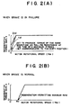
- the failed-time map and normal-time map stored in the memory unit 13 are maps which make it possible to set a regenerative torque gain in accordance with a motor rotational speed N M as is illustrated in FIGS. 2A and 2B.
- the failed-time map provides a certain regenerative gain even when the motor rotational speed N M drops to 0, that is, the motor 2 stops rotation as illustrated in FIG. 2A.
- the motor 2 stops rotation as illustrated in FIG. 2A.
- braking force is therefore produced by regenerative braking instead of braking force by the brake 11 so that the vehicle can be braked or stopped.
- the computing means 14A is inputted with detection information from failure detection means 22 arranged for the detection of a failure in the mechanical brake system, detection information on a stroke of the brake pedal 5 (brake pedal stroke) from brake pedal stroke detection means 23, detection information on a rotational speed (the number of rotations) N M of the motor 2 from motor rotational speed detection means 24 and information of a gear position of the transmission from the gear position detecting means 21, and based on these failure information, brake pedal stroke information, motor rotational speed information and gear position information and the map stored in the memory unit 13, computes a target regenerative torque.
- the failure detection means 22 can detect whether the brake is normal or in failure, for example, from the degree of a deceleration of the vehicle relative to an operation degree of the brake (namely, a stroke of the brake pedal).
- the brake pedal stroke is detected by the brake pedal stroke detection means 23 whereas the degree of the deceleration of the vehicle is calculated relying upon a vehicle speed sensor (not shown) which is often mounted on the vehicle.
- the computing means 14A uses the failed-time map stored in the memory unit 13 when the brake 11 is in failure, but employs the normal-time map stored in the memory unit 13 during normal operation of the brake 11. Corresponding to a rotational speed (the number of rotations) N M of the motor 2 and a shift position (gear position), a regenerative torque gain is then determined from the corresponding map. By computing the product of this regenerative torque gain and a brake pedal stroke, a regenerative torque is determined.
- the regenerative torque is proportional to the brake pedal stroke as mentioned above, the regenerative torque becomes maximum when the brake pedal stroke becomes maximum, provided that the motor rotational speed is the same.
- the correction means 14b receives detection information on the grade of a road from road grade detection means 25, and corrects a regenerative torque gain so that the regenerative torque gain becomes greater as the downhill grace of the road increases but conversely, the regenerative torque gain becomes smaller as the road becomes more uphill. Further, no correction is effected when a road is flat.
- the computing means 14A computes a regenerative torque by using a regenerative torque gain which has been subjected, as needed, to such a correction as described above.
- a regenerative torque is controlled through the motor controller 4.
- step S10 it is first detected from brake switch information whether the brake pedal 10 has been depressed. If the brake pedal 10 is not detected to have been depressed, no regeneration control is performed. If the brake pedal 10 is however detected to have been depressed, the routine then advances to step S20, where it is determined whether there was a failure in the mechanical brake 11.
- step S30 where the normal-time map is selected by the computing means 14A and a regenerative torque gain corresponding to a motor rotational speed N M is determined from this normal-time map .
- step S40 the routine advances to step S40, where the failed-time map is selected by the computing means 14A and a regenerative torque gain corresponding to a motor rotational speed N M is determined from this failed-time map .
- step S50 the regenerative torque gain is corrected by the correction means 14B on the basis of a road grade from the road grade detection means 25.
- This correction is performed in such a way that, when the road is a downhill, the regenerative torque gain is corrected to become greater as the descending grade becomes steeper but, when the road is an uphill, the regenerative torque gain is corrected to become smaller as the ascending grade becomes steeper.
- step S60 the regenerative torque gain determined in step S30 or S50 is multiplied by a brake pedal stroke detected by the brake pedal stroke detection means 23 so that a regenerative torque is set.
- the regeneration of the motor is controlled through the motor controller 4 so that the regenerative torque so set is achieved.
- the regenerative braking force at the failed time is set so that the regenerative torque becomes equal to or smaller than the rolling resistance of the vehicle without exception especially when the vehicle is at a stop.
- the vehicle at the stop is therefore surely prevented from such a problem as moving backward, and can be safely stopped.
- the regenerative torque is preventing from suddenly changing relative to the motor rotational speed N M so that smooth control of regenerative braking can be performed.
- the regenerative braking force at the failed time is corrected in accordance with the grade of a road so that on a downhill, the regenerative braking force is increased in accordance with the steepness of the descent and on an uphill, the regenerative braking force is reduced in accordance with the steepness of the ascent. It is therefore possible to ensure braking force corresponding to each downhill or uphill. Owing to the regenerative braking force enhanced especially on a downhill, sufficient braking force can be secured on the downhill although this is the most serious problem when the mechanical brake fails. The reliability of the automobile in the event of such an emergency has therefore been improved further.
- a regenerative torque gain is set based on one of the maps and a regenerative torque is then determined from the regenerative torque gain. It is however not absolutely necessary to use such maps. Namely, a regenerative torque can be determined in accordance with a motor rotational speed, a brake pedal stroke, a grade and the like by using a computing equation of similar setting characteristics of regenerative torques as the above-described maps or by storing in certain memory means such setting characteristics of regenerative torques as those shown in the maps and using such characteristics.
- the transmission 8 is not limited to the two-speed transmission. Even a transmission having a greater number of speeds can still bring about similar effects as the above-described embodiment by providing the failed-time map with regenerative torque gains set for the individual gear positions in the low motor rotational speed range.
- the braking control system of the present invention for the electric automobile, greater regenerative braking is applied by the drive motor when the mechanical brake system is in failure than when the mechanical brake system is normal. Even when the mechanical brake system is in failure, it is therefore still possible to ensure braking performance by regenerative braking force of the drive motor in the event of such an emergency of the automobile while making it possible to avoid or reduce a regenerative-braking-induced energy loss when the mechanical brake system is normal. This has made it possible to provide the electric automobile with improved reliability.
Landscapes
- Engineering & Computer Science (AREA)
- Power Engineering (AREA)
- Transportation (AREA)
- Mechanical Engineering (AREA)
- Life Sciences & Earth Sciences (AREA)
- Sustainable Development (AREA)
- Sustainable Energy (AREA)
- Physics & Mathematics (AREA)
- Electromagnetism (AREA)
- Electric Propulsion And Braking For Vehicles (AREA)
- Regulating Braking Force (AREA)
Abstract
Description
- This invention relates to an electric automobile which runs by driving wheels with an electric motor, and especially to a braking control system for an electric automobile so that braking of a vehicle is controlled relying upon regenerative braking by a motor.
- In recent years, electric automobiles each of which drives wheels by an electric motor instead of an internal combustion engine have attracted an increasing interest from the viewpoint of prevention of air pollution and reduction of vehicle noise.
- These electric automobiles easily allow so-called regenerative braking. This regenerative braking can be performed by limiting a supply of electric power to a drive motor and converting the motor into a power-generating state. At this time, a load is applied to each drive wheel so that, while braking the drive wheel, rotational energy of the drive wheel can be recovered as electric energy.
- Incidentally, regenerative braking in such electric automobiles is controlled so that a regenerative torque has such characteristics as shown in FIG. 4. Described specifically, at a low motor rotational speed, application of a regenerative torque causes a vehicle to move backward after the vehicle is brought to halt subsequent to a deceleration. A large electric current is also required for inducing the regeneration so that the motor produces more heat, although recoverable electric power is small, leading to a negative effect from the standpoint of energy. To avoid these problems, control is therefore performed so that no regenerative torque is produced at a certain rotational speed (for example, NO) or lower.
- Techniques for producing a regenerative torque even at a low motor rotational speed have been proposed to date. For example, the technique disclosed in Japanese Patent Application Laid-Open (Kokai) No. SHO 62-95903 performs PI (proportional and integral) control so that the rotational speed of a motor becomes 0 even when the motor is in a near-stop range (low-speed range).
- As a consequence, it is possible to produce a regenerative torque even at a low speed while preventing a vehicle from moving backward subsequent to stopping of the vehicle. This however results in a negative effect from the standpoint of energy because at such a low speed, electric power consumed for inducing regeneration becomes greater than recoverable electric power as mentioned above.
- If regenerative braking is always applied as described above, an inconvenience therefore arises in that the coverable distance of an electric automobile is reduced. Further, production of heat by the motor also becomes a problem.
- Upon applying brakes at a normal time in an electric automobile, mechanical brakes such as foot brakes are operated as in ordinary automobiles of the internal combustion type, and like an engine brake in the automobiles of the internal combustion engines, regenerative braking is applied further in addition to the mechanical brakes.
- To stop a conventional electric automobile which is running at such a low speed that the rotational speed of its motor is equal to or lower than a predetermined value (for example, NO), only the above-mentioned mechanical brakes are usually relied upon since it is not desired to produce a regenerative torque.
- If the mechanical brakes fail, no braking force is therefore applied when the motor is at a low speed. Although it is of course possible to provide the mechanical brakes themselves with a fail-safe function, it is desired to make it possible to appropriately use regenerative braking of the electric automobile in the event of a failure in the mechanical brakes because the regenerative braking can produce a substantially large regenerative torque even at a low speed.
- With the foregoing problems in view, the present invention has as an object thereof the provision of a braking control system for an electric automobile so that regenerative braking is appropriately used in the event of a failure in mechanical brakes to ensure stopping of a vehicle while making it possible to either avoid or reduce an energy loss due to regenerative braking when the mechanical brakes are normal.
- The present invention provides a braking control system for an electric automobile, said brake control system permitting combined use of mechanical braking by a mechanical brake system and regenerative braking by a drive motor upon application of brakes, comprising failure detection means for detecting whether said mechanical brake system is normal or in failure, and regenerative braking control means for receiving a detection signal from said failure detection means upon application of said brakes and then performing control of regenerative braking by said drive motor, wherein said regenerative braking control means performs said control of regenerative braking by said drive motor so that greater braking force is produced when a failure in said mechanical brake system is detected by said failure detection means than when said mechanical brake system is detected to be normal.
- Owing to such features, if the mechanical brake system is normal, regenerative braking force is reduced to perform braking based primarily on the normal mechanical brake system. This can reduce an energy loss which is associated with regenerative braking at a low speed, and can also reduce generation of heat from the motor. If the mechanical brake system is in failure, on the other hand, braking is performed by regenerative braking so that a vehicle can be stopped surely.
- In addition to the above such features, said braking control system may further comprise motor rotational speed detection means for detecting a rotational speed of said motor. Upon receipt of detection signals from said failure detection means and said motor rotational speed detection means, said regenerative braking control means may perform said control of regenerative braking of said motor so that said regenerative braking is applied only in a range equal to and higher than a predetermined rotational speed of said motor when said mechanical brake system is detected to be normal but is always applied irrespective of a rotational speed of said motor when said failure is detected.
- Owing to such features, if the mechanical brake system is normal, the regenerative braking is not performed when the motor is at a low rotational speed. Braking is therefore performed only by the normal mechanical brake system. This can avoid an energy loss which is associated with regenerative braking at a low speed, and can also avoid the generation of heat from the motor. If the mechanical brake system is in failure, on the other hand, regenerative braking is performed even when the motor is at a low rotational speed. By this regenerative braking, braking is conducted without failure so that the vehicle can be stopped.
- The braking control system may further comprise motor rotational speed detection means for detecting a rotational speed of said motor and brake pedal stroke detection means for detecting a brake pedal stroke by a driver. Upon receipt of detection signals from said failure detection means, said motor rotational speed detection means and said brake pedal stroke detection means, said regenerative braking control means may perform the control of regenerative braking of said motor so that regenerative braking force preset corresponding to said rotational speed of said motor and said brake pedal stroke is produced when said failure is detected.
- Owing to such features, if the mechanical brake means is in failure, a regenerative torque can be set corresponding to a rotational speed of the motor and a stroke of the brake pedal. It is therefore possible to apply regenerative braking force which is adequate for the rotational speed of the motor and also reflects a driver's intention of braking.
- In this case, said regenerative braking control means can be designed to perform said control of regenerative braking force of said motor upon detection of said failure so that said regenerative braking force is increased more as said rotational speed of said motor becomes lower.
- Owing to such features, a regenerative torque can be set corresponding to a rotational speed of the motor and a stroke of the brake pedal. It is therefore possible to apply regenerative braking force which is adequate for the rotational speed of the motor and also reflects the driver's intention of braking. In particular, if the mechanical brake means is normal, no regenerative braking is performed when the motor is at a low rotational speed. It is therefore possible to achieve easy and sure control on regenerative braking. Further, because regenerative braking is applied corresponding to an operation of the brake pedal, braking can be performed reflecting the driver's intention even if the mechanical brake system is in failure.
- In addition, the regenerative braking control means can be designed to perform the control of regenerative braking of the motor so that, when said failure is detected and said rotational speed of said motor is detected to be zero, said regenerative braking torque available at a maximum value of said brake pedal stroke becomes equal to or smaller than rolling resistance of said vehicle.
- Owing to such features, even if the stroke of the brake pedal is brought to the maximum value when said failure is detected and said rotational speed of said motor is detected to be zero, the resulting regenerative braking torque becomes equal to or smaller than the rolling resistance of the vehicle. This makes it possible to avoid an inconvenience such as the stopped vehicle being caused to move backward by the regenerative torque, and hence to surely and safely stop the vehicle.
- Alternatively, the braking control system may further comprise gear position detecting means for detecting a gear position of a transmission mounted on said vehicle, and the regenerative braking control means may be designed to perform the control of regenerative braking of the motor so that, when said failure is detected, said regenerative braking force is increased more based on a detection signal from said gear position detecting means as said gear position has a higher gear position.
- Owing to such features, a regenerative torque corresponding to a gear position can be applied. At a low vehicle speed, a stable regenerative torque can be obtained irrespective of the gear position. It is therefore possible to stably perform regenerative braking even when the mechanical brake system is in failure.
- The braking control system may further comprise road grade detection means for detecting a grade of a road on which said vehicle is running. The regenerative braking control means can be designed to perform the control of regenerative braking of the motor so that based on a detection signal from said road grade detection means, said regenerative braking force is increased more as the downward grade of said road increases.
- Owing to such features, large braking force which is required on a downhill can be obtained even when the mechanical brake means is in failure. The reliability of the automobile in the event of such an emergency can therefore be improved.
-
- FIG. 1 is a schematic block diagram showing a braking control system according to one embodiment of the present invention for an automobile;
- FIG. 2A and 2B both illustrate maps useful in controlling braking by the braking control system according to the one embodiment of the present invention for the automobile, in which FIG. 2A shows a map for use when mechanical brake means is in failure while FIG. 2B depicts a map for use when the mechanical brake means is normal;
- FIG. 3 is a flow chart illustrating a braking control operation by the braking control system according to the one embodiment of the present invention for the automobile; and
- FIG. 4 is a diagram illustrating braking control characteristics of a conventional braking control system for an electric automobile.
- With reference to FIG. 1 through FIG. 3, a description will hereinafter be made about the braking control system according to the one embodiment of the present invention for the automobile.
- In FIG. 1, numeral 1 indicates a battery. This battery 1 is repeatedly rechargeable by an external battery charger, which is not equipped with a vehicle. Designated at
numeral 2 is a drive motor to which electric power is supplied from the battery 1. By thismotor 2, eachdrive wheel 3 of the automobile is driven. Arranged between the battery 1 and themotor 2 is amotor controller 4, through which the electric power from the battery 1 is adjusted to a predetermined level and is supplied to themotor 2. - The
motor controller 4 is in turn controlled by adrive management controller 5. Described specifically, thedrive management controller 5 is inputted with a stroke of an accelerator position 6 (accelerator position) through anaccelerator 7 so that through themotor controller 4, an output of themotor 2 is controlled primarily to conform with the accelerator position. - Further, a transmission (speed-change gear) 8 is interposed between the
motor 2 and thedrive wheel 3 so that a rotational speed of themotor 2 is shifted and then transmitted to thedrive wheel 3. A gear position of this transmission is selected by operating ashift lever 9. In the illustrated embodiment, thetransmission 8 is assumed to be a 2-forward/1-reverse transmission. - Based on a gear position selected through the shift lever 9 (selected gear position), the
drive management controller 5 performs control so that, when theshift lever 9 is set in the forward range, the motor is rotated forward corresponding to an accelerator position but, when theshift lever 9 is set in the reverse range, the motor is reversed corresponding to an accelerator position. Information on the gear position selected by theshift lever 9 is inputted from a gear position detecting means (selector switch or the like) 21, which serves to detect the gear position, to thedrive management controller 5. In the reverse range, the speed-change gears themselves are set at a 1st speed. - This electric automobile is also designed in such a way that, when a
brake pedal 10 is depressed, braking is applied by a mechanical brake system (hereinafter called the "mechanical brake" or simply the "brake") 11 and regenerative braking is also performed by themotor 2. Control of this regenerative braking is effected by a regenerative braking control function unit (regeneration control means) 12, which is arranged in thedrive management controller 5, on the basis of information on detection of an actuation of brakes (information indicative of an "on" position of a brake switch 20) from thebrake switch 20. Depending on whether the brake is normal or is in failure, this regenerative control means 12 controls a regenerative torque, which is produced by themotor 2, in accordance with a brake pedal stroke, a revolution speed NM of themotor 2 and a gear position of thetransmission 8 orshift lever 9. - A description will now be made of the regenerative control means 12. This regenerative control means 12 is provided with a memory unit (memory means) 13, a regenerative
torque setting unit 14 and a command unit (command means) 15. - Among these, the
memory unit 13 stores a failed-time map and a normal-time map to be described subsequently herein. The regenerativetorque setting unit 14 is provided with computing means 14A and correction means 14B. The computing means 14A computes a target regenerative torque from various detection information and the maps stored in thememory unit 13. However, a regenerative torque gain which is employed at the computing means 14A is suitably corrected by the correction means 14B. Further, thecommand unit 15 outputs a command signal to themotor control 4 in accordance with a value of regenerative torque so set. - The failed-time map and normal-time map stored in the
memory unit 13 are maps which make it possible to set a regenerative torque gain in accordance with a motor rotational speed NM as is illustrated in FIGS. 2A and 2B. - Of these, the normal-time map defines a lower limit NO of motor rotational speeds capable of producing regenerative torques, a regeneration-permitting minimum rpm, as shown in FIG. 2B. If the motor rotational speed NM drops to or below this lower limit NO, the regenerative torque gain becomes 0 so that no regenerative torque is produced. As the motor rotational speed NM exceeds this lower limit NO, the regenerative torque gain gradually increases and then remains at a maximum value (= 1) in a medium-speed range.
- As mentioned above, when the motor rotational speed NM is low, a large electric current is required for regeneration, thereby inducing the generation of heat from the motor and an energy loss. It is to avoid these problems that no regenerative braking is performed in the low range of motor rotational speeds NM as described above. By gradually increasing the regenerative torque gain with the motor rotational speed NM, the regenerative torque is prevented from suddenly changing relative to the motor rotational speed NM, thereby permitting smooth control of generative braking.
- On the other hand, the failed-time map provides a certain regenerative gain even when the motor rotational speed NM drops to 0, that is, the
motor 2 stops rotation as illustrated in FIG. 2A. Even when themotor 2 is at a low speed (namely, when the automobile is at a low speed) or even when themotor 2 is stopped (namely, when the automobile is stopped), braking force is therefore produced by regenerative braking instead of braking force by thebrake 11 so that the vehicle can be braked or stopped. - This failed-time map is designed so that the regenerative torque gain remains at a maximum value (= 1) in the low and medium speed ranges of the motor rotational speed NM but gradually decreases when the motor rotational speed NM approaches 0. Accordingly, the regenerative torque gain becomes minimum when the motor rotational speed NM is 0. This is to make a regenerative torque equal to or lower than the rolling resistance of the vehicle around the motor rotational speed NM = 0 so that the vehicle at a stop is prevented from moving backward. When the motor rotational speed NM increases from 0, the vehicle obviously becomes less likely to move backward. The regenerative torque gain hence gradually increases to reach the maximum value so that vehicle braking force can be obtained as needed.
- In the failed-time map, the regenerative torque gain around the motor rotational speed NM = 0 is set depending on the gear position. Described specifically, the regenerative torque gain around the motor rotational speed NM = 0 is set greater for the higher gear position (the 2nd speed) than for the lower gear position (the 1st speed), because the force applied to the drive wheels becomes smaller at the higher gear position of a higher gear ratio than at the lower gear position of a lower gear ratio so that to obtain a similar regenerative torque, the regenerative torque gain has to be made greater at the higher gear position than at the lower gear position. At the motor rotational speed NM = 0, the regenerative torque gain for the higher gear position and that for the lower gear position therefore correspond to their gear ratios, respectively.
- The computing means 14A is inputted with detection information from failure detection means 22 arranged for the detection of a failure in the mechanical brake system, detection information on a stroke of the brake pedal 5 (brake pedal stroke) from brake pedal stroke detection means 23, detection information on a rotational speed (the number of rotations) NM of the
motor 2 from motor rotational speed detection means 24 and information of a gear position of the transmission from the gear position detecting means 21, and based on these failure information, brake pedal stroke information, motor rotational speed information and gear position information and the map stored in thememory unit 13, computes a target regenerative torque. - The failure detection means 22 can detect whether the brake is normal or in failure, for example, from the degree of a deceleration of the vehicle relative to an operation degree of the brake (namely, a stroke of the brake pedal). In this case, the brake pedal stroke is detected by the brake pedal stroke detection means 23 whereas the degree of the deceleration of the vehicle is calculated relying upon a vehicle speed sensor (not shown) which is often mounted on the vehicle.
- The computing means 14A uses the failed-time map stored in the
memory unit 13 when thebrake 11 is in failure, but employs the normal-time map stored in thememory unit 13 during normal operation of thebrake 11. Corresponding to a rotational speed (the number of rotations) NM of themotor 2 and a shift position (gear position), a regenerative torque gain is then determined from the corresponding map. By computing the product of this regenerative torque gain and a brake pedal stroke, a regenerative torque is determined. - As the regenerative torque is proportional to the brake pedal stroke as mentioned above, the regenerative torque becomes maximum when the brake pedal stroke becomes maximum, provided that the motor rotational speed is the same. The regenerative torque gain at the motor rotational speed NM = 0 in the above-described failed-time map is therefore set so that, even if the brake pedal is operated over its maximum stroke and the regenerative torque becomes the maximum, the regenerative torque does not exceed the rolling resistance of the vehicle.
- The correction means 14b receives detection information on the grade of a road from road grade detection means 25, and corrects a regenerative torque gain so that the regenerative torque gain becomes greater as the downhill grace of the road increases but conversely, the regenerative torque gain becomes smaller as the road becomes more uphill. Further, no correction is effected when a road is flat.
- Accordingly, the computing means 14A computes a regenerative torque by using a regenerative torque gain which has been subjected, as needed, to such a correction as described above.
- In accordance with a command from the command means 15, a regenerative torque is controlled through the
motor controller 4. - As the braking control system according to the one embodiment of the present invention for the electric automobile is constructed as described above, setting of its regenerative torque is performed, for example, as illustrated in FIG. 3.
- Namely, it is first detected from brake switch information whether the
brake pedal 10 has been depressed (step S10). If thebrake pedal 10 is not detected to have been depressed, no regeneration control is performed. If thebrake pedal 10 is however detected to have been depressed, the routine then advances to step S20, where it is determined whether there was a failure in themechanical brake 11. - Unless there is a failure in the mechanical brake 11 (in other words, if the mechanical brake is normal), the routine then advances to step S30, where the normal-time mapis selected by the computing means 14A and a regenerative torque gain corresponding to a motor rotational speed NM is determined from this normal-time map
 . If there is a failure in the
mechanical brake 11, on the other hand, the routine advances to step S40, where the failed-time mapis selected by the computing means 14A and a regenerative torque gain corresponding to a motor rotational speed NM is determined from this failed-time map .
. - The routine then advances to step S50, where the regenerative torque gain is corrected by the correction means 14B on the basis of a road grade from the road grade detection means 25. This correction is performed in such a way that, when the road is a downhill, the regenerative torque gain is corrected to become greater as the descending grade becomes steeper but, when the road is an uphill, the regenerative torque gain is corrected to become smaller as the ascending grade becomes steeper.
- In step S60, the regenerative torque gain determined in step S30 or S50 is multiplied by a brake pedal stroke detected by the brake pedal stroke detection means 23 so that a regenerative torque is set.
- After a regenerative torque has been set as described above, the regeneration of the motor is controlled through the
motor controller 4 so that the regenerative torque so set is achieved. - As a consequence, when the mechanical brake is normal, no regenerative braking is performed on the basis of the normal-time mapshown in FIG. 2B when the
motor 2 is at a low speed. Normally, it is therefore possible to prevent the generation of heat from the motor and to keep the equipment in good condition, and owing to avoidance of an energy loss, further to ensure a sufficient coverable distance for the automobile. - When the mechanical brake is in failure, on the other hand, regenerative braking is performed based on the failed-time mapshown in FIG. 2A even when the
motor 2 is at a low speed. Braking and stopping of the vehicle can therefore be achieved without failure while the motor produces regenerative braking force in place of themechanical brake 11 until the vehicle stops. It is therefore possible to provide the automobile with improved reliability in the event of such an emergency. - Further, the regenerative braking force at the failed time is set so that the regenerative torque becomes equal to or smaller than the rolling resistance of the vehicle without exception especially when the vehicle is at a stop. The vehicle at the stop is therefore surely prevented from such a problem as moving backward, and can be safely stopped. By gradually increasing the regenerative torque gain with the motor rotational speed NM, the regenerative torque is preventing from suddenly changing relative to the motor rotational speed NM so that smooth control of regenerative braking can be performed.
- Further, the regenerative braking force at the failed time is corrected in accordance with the grade of a road so that on a downhill, the regenerative braking force is increased in accordance with the steepness of the descent and on an uphill, the regenerative braking force is reduced in accordance with the steepness of the ascent. It is therefore possible to ensure braking force corresponding to each downhill or uphill. Owing to the regenerative braking force enhanced especially on a downhill, sufficient braking force can be secured on the downhill although this is the most serious problem when the mechanical brake fails. The reliability of the automobile in the event of such an emergency has therefore been improved further.
- In the above-described embodiment, it is designed to perform no regenerative braking at a low speed of the
motor 2 when themechanical brake 11 is normal but to perform regenerative braking even at a low speed of themotor 2 when themechanical brake 11 is in failure. It is also possible to achieve the prevention of production of heat from the motor and the maintenance of the equipment to certain extents by performing regenerative braking while limiting the production of regenerative braking force instead of completely preventing regenerative braking even at a low speed of themotor 2 when the mechanical brake is normal. This also makes it possible to provide the automobile with a sufficient coverable distance owing to the reduction of the energy loss. - In this case, greater regenerative braking force can be produced when the
mechanical brake 11 is in failure than when themechanical brake 11 is normal, whereby regenerative force sufficient to replace themechanical brake 11 can be produced until the vehicle stops. This makes it possible to perform accurate braking and stopping of the automobile. It is therefore possible to provide the automobile with improved reliability in the event of such an emergency. - In the above-described embodiment, a regenerative torque gain is set based on one of the maps and a regenerative torque is then determined from the regenerative torque gain. It is however not absolutely necessary to use such maps. Namely, a regenerative torque can be determined in accordance with a motor rotational speed, a brake pedal stroke, a grade and the like by using a computing equation of similar setting characteristics of regenerative torques as the above-described maps or by storing in certain memory means such setting characteristics of regenerative torques as those shown in the maps and using such characteristics.
- The
transmission 8 is not limited to the two-speed transmission. Even a transmission having a greater number of speeds can still bring about similar effects as the above-described embodiment by providing the failed-time map with regenerative torque gains set for the individual gear positions in the low motor rotational speed range. - According to the braking control system of the present invention for the electric automobile, greater regenerative braking is applied by the drive motor when the mechanical brake system is in failure than when the mechanical brake system is normal. Even when the mechanical brake system is in failure, it is therefore still possible to ensure braking performance by regenerative braking force of the drive motor in the event of such an emergency of the automobile while making it possible to avoid or reduce a regenerative-braking-induced energy loss when the mechanical brake system is normal. This has made it possible to provide the electric automobile with improved reliability.
Claims (7)
- A braking control system for an electric automobile, said brake control system permitting combined use of mechanical braking by a mechanical brake system (11) and regenerative braking by a drive motor (2) upon application of brakes, comprising:failure detection means (22) for detecting whether said mechanical brake system (11) is normal or in failure, andregenerative braking control means (12) for receiving a detection signal from said failure detection means (22) upon application of said brakes and then performing control of regenerative braking by said drive motor (2);wherein said regenerative braking control means (12) performs said control of regenerative braking by said drive motor (2) so that greater braking force is produced when a failure in said mechanical brake system (11) is detected by said failure detection means (22) than when said mechanical brake system (11) is detected to be normal.
- The braking control system according to claim 1, wherein said braking control system further comprises motor rotational speed detection means (24) for detecting a rotational speed of said motor (2); and upon receipt of detection signals from said failure detection means (22) and said motor rotational speed detection means (24), said regenerative braking control means (12) performs said control of regenerative braking of said motor (2) so that said regenerative braking is applied only in a range equal to and higher than a predetermined rotational speed of said motor (2) when said mechanical brake system (11) is detected to be normal but is always applied irrespective of a rotational speed of said motor (2) when said failure is detected.
- The braking control system according to claim 1, wherein said braking control system further comprises motor rotational speed detection means (24) for detecting a rotational speed of said motor (2) and brake pedal stroke detection means (23) for detecting a brake pedal stroke by a driver; and upon receipt of detection signals from said failure detection means (22), said motor rotational speed detection means (24) and said brake pedal stroke detection means (23), regenerative braking of said motor (2) is controlled so that regenerative braking force preset corresponding to said rotational speed of said motor and said brake pedal stroke is produced when said failure is detected.
- The braking control system according to claim 3, wherein upon detection of said failure, said regenerative braking control means (12) performs said control of regenerative braking force of said motor (2) so that said regenerative braking force is increased more as said rotational speed of said motor (2) becomes lower.
- The braking control system according to claim 3, wherein, when said failure is detected and said rotational speed of said motor (2) is detected to be zero, said regenerative braking control means (12) performs said control of regenerative braking of said motor (2) so that said regenerative braking torque available at a maximum value of said brake pedal stroke becomes equal to or smaller than rolling resistance of said vehicle.
- The braking control system according to claim 3, wherein said braking control system further comprises gear position detecting means (21) for detecting a gear position of a transmission mounted on said vehicle; and, when said failure is detected, said regenerative braking control means (12) performs said control of regenerative braking of said motor (2) so that based on a detection signal from said gear position detecting means (21), said regenerative braking force is increased more as said gear position has a higher gear position.
- The braking control system according to claim 3, wherein said braking control system further comprises road grade detection means (25) for detecting a grade of a road on which said vehicle is running; and based on a detection signal from said road grade detection means (25), said regenerative braking control means (12) performs said control of regenerative braking of said motor (2) so that said regenerative braking force is increased more as a downhill grade of said road increases.
Applications Claiming Priority (4)
| Application Number | Priority Date | Filing Date | Title |
|---|---|---|---|
| JP294378/94 | 1994-11-29 | ||
| JP29437894 | 1994-11-29 | ||
| JP29437894 | 1994-11-29 | ||
| PCT/JP1995/002423 WO1996016831A1 (en) | 1994-11-29 | 1995-11-28 | Braking control device for an electric car |
Publications (3)
| Publication Number | Publication Date |
|---|---|
| EP0770511A1 true EP0770511A1 (en) | 1997-05-02 |
| EP0770511A4 EP0770511A4 (en) | 1998-05-27 |
| EP0770511B1 EP0770511B1 (en) | 2000-03-15 |
Family
ID=17806953
Family Applications (1)
| Application Number | Title | Priority Date | Filing Date |
|---|---|---|---|
| EP95937204A Expired - Lifetime EP0770511B1 (en) | 1994-11-29 | 1995-11-28 | Braking control device for an electric car |
Country Status (4)
| Country | Link |
|---|---|
| US (1) | US5775784A (en) |
| EP (1) | EP0770511B1 (en) |
| DE (1) | DE69515668T2 (en) |
| WO (1) | WO1996016831A1 (en) |
Cited By (7)
| Publication number | Priority date | Publication date | Assignee | Title |
|---|---|---|---|---|
| WO1999007804A2 (en) * | 1997-08-11 | 1999-02-18 | Tavera, Ivon | Method for storing energy in the form of thermal energy by means of high-temperature accumulators |
| DE19810656A1 (en) * | 1998-03-12 | 1999-09-16 | Itt Mfg Enterprises Inc | Braking control method for electric or hybrid vehicles |
| FR2977538A1 (en) * | 2011-07-05 | 2013-01-11 | Renault Sa | Method for simulating engine braking of e.g. electric vehicle, involves transmitting substitution control toward complementary braking unit, where substitution control is generated from potential braking value of regenerative braking unit |
| CN108778825A (en) * | 2016-05-27 | 2018-11-09 | 本田技研工业株式会社 | Electric vehicle |
| CN110450637A (en) * | 2019-07-31 | 2019-11-15 | 东风柳州汽车有限公司 | The fault detection control method of electric car power distribution equipment |
| CN112744083A (en) * | 2019-10-30 | 2021-05-04 | 北京新能源汽车股份有限公司 | Safety control method and device for brake system fault and electric automobile |
| FR3138095A1 (en) * | 2022-07-21 | 2024-01-26 | Psa Automobiles Sa | Motor vehicle braking curve mapping |
Families Citing this family (47)
| Publication number | Priority date | Publication date | Assignee | Title |
|---|---|---|---|---|
| JPH1127802A (en) * | 1997-07-03 | 1999-01-29 | Toyota Motor Corp | Braking controller for electric vehicle |
| US6076898A (en) * | 1997-04-18 | 2000-06-20 | Aisin Seiki Kabushiki Kaisha | Braking control system for a four-wheel drive vehicle |
| JP3541621B2 (en) * | 1997-06-10 | 2004-07-14 | トヨタ自動車株式会社 | Vehicle braking system |
| JPH11289610A (en) * | 1998-04-01 | 1999-10-19 | Nissan Motor Co Ltd | Auxiliary brake for hybrid car |
| JP3607991B2 (en) | 1999-06-08 | 2005-01-05 | トヨタ自動車株式会社 | Braking force control device for vehicle |
| DE19952781A1 (en) * | 1999-11-03 | 2001-06-13 | Daimler Chrysler Ag | Method for braking a vehicle |
| JP2001251701A (en) * | 2000-03-06 | 2001-09-14 | Hitachi Ltd | Control device for electric car |
| JP3941695B2 (en) * | 2003-01-08 | 2007-07-04 | 株式会社豊田自動織機 | Vehicle travel control device |
| DE10328786B4 (en) * | 2003-06-26 | 2015-03-12 | Robert Bosch Gmbh | Method for operating a motor vehicle |
| JP2006035967A (en) * | 2004-07-26 | 2006-02-09 | Hitachi Ltd | Braking control device for automobile |
| US20060047400A1 (en) * | 2004-08-25 | 2006-03-02 | Raj Prakash | Method and apparatus for braking and stopping vehicles having an electric drive |
| US7311163B2 (en) * | 2004-11-16 | 2007-12-25 | Eaton Corporation | Regeneration and brake management system |
| KR20080051492A (en) * | 2006-12-06 | 2008-06-11 | 현대자동차주식회사 | Method for control regenerative braking of electric vehicle |
| JP4882717B2 (en) * | 2006-12-13 | 2012-02-22 | トヨタ自動車株式会社 | Braking / driving force control device |
| US7854681B2 (en) * | 2007-04-30 | 2010-12-21 | Caterpillar Inc | System for controlling a machine with a continuously variable transmission |
| JP4458300B2 (en) * | 2007-10-25 | 2010-04-28 | 本田技研工業株式会社 | Electric vehicle and regeneration control method for electric vehicle |
| US8352138B2 (en) * | 2007-11-30 | 2013-01-08 | Caterpillar Inc. | Dynamic control system for continuously variable transmission |
| US20100025167A1 (en) * | 2008-07-31 | 2010-02-04 | Caterpillar Inc. | Braking system for an off-highway machine involving electric retarding integrated with service brakes |
| US8281908B2 (en) | 2008-08-29 | 2012-10-09 | Caterpillar Inc. | Brake cooling fluid diverter for an off-highway machine |
| US8054016B2 (en) | 2008-09-15 | 2011-11-08 | Caterpillar Inc. | Retarding energy calculator for an electric drive machine |
| US9063202B2 (en) * | 2008-09-15 | 2015-06-23 | Caterpillar Inc. | Method and apparatus for detecting phase current imbalance in a power generator |
| US8253357B2 (en) * | 2008-09-15 | 2012-08-28 | Caterpillar Inc. | Load demand and power generation balancing in direct series electric drive system |
| US8140206B2 (en) | 2008-09-15 | 2012-03-20 | Caterpillar Inc. | Engine load management for traction vehicles |
| US7795825B2 (en) | 2008-09-15 | 2010-09-14 | Caterpillar Inc | Over-voltage and under-voltage management for electric drive system |
| US7956762B2 (en) * | 2008-09-15 | 2011-06-07 | Caterpillar Inc. | Method and apparatus for power generation failure diagnostics |
| US7918296B2 (en) * | 2008-09-15 | 2011-04-05 | Caterpillar Inc. | Cooling system for an electric drive machine and method |
| US7996163B2 (en) * | 2008-09-15 | 2011-08-09 | Caterpillar Inc. | Method and apparatus for detecting a short circuit in a DC link |
| US8410739B2 (en) * | 2008-09-15 | 2013-04-02 | Caterpillar Inc. | Method and apparatus for determining the operating condition of generator rotating diodes |
| US20100065356A1 (en) * | 2008-09-15 | 2010-03-18 | Caterpillar Inc. | Electric powertrain for off-highway trucks |
| US8324846B2 (en) * | 2008-09-15 | 2012-12-04 | Caterpillar Inc. | Electric drive retarding system and method |
| JP5293273B2 (en) * | 2009-03-02 | 2013-09-18 | 日産自動車株式会社 | Regenerative control device for electric vehicle |
| US8626368B2 (en) | 2010-09-07 | 2014-01-07 | Caterpillar Inc. | Electric drive power response management system and method |
| DE102010046172A1 (en) * | 2010-09-23 | 2012-04-26 | Jungheinrich Aktiengesellschaft | Method for operating an electrically driven industrial truck |
| JP5915208B2 (en) * | 2012-01-31 | 2016-05-11 | 日産自動車株式会社 | Regenerative brake control device for electric vehicle |
| JP2014076715A (en) * | 2012-10-10 | 2014-05-01 | Mitsubishi Motors Corp | Brake lamp control device |
| US9616755B2 (en) * | 2012-10-22 | 2017-04-11 | Kawasaki Jukogyo Kabushiki Kaisha | Regenerative brake control system of electric vehicle |
| KR101470149B1 (en) | 2013-04-30 | 2014-12-05 | 현대자동차주식회사 | Fail diagnosis method for brake system of vehicle |
| CN103264638B (en) * | 2013-05-31 | 2015-04-01 | 长沙理工大学 | Spring type automobile braking energy recycling device |
| KR101583926B1 (en) * | 2014-05-12 | 2016-01-08 | 현대자동차주식회사 | Method for detecting malfunction of brake system using yawrate |
| JP6514895B2 (en) * | 2015-01-06 | 2019-05-15 | 川崎重工業株式会社 | Drive control system for working machine, working machine including the same, and drive control method thereof |
| US9937916B2 (en) * | 2015-07-21 | 2018-04-10 | Ford Global Technologies, Llc | Methods and system for reducing transmission shifting |
| KR101777329B1 (en) * | 2016-08-10 | 2017-09-11 | 엘지전자 주식회사 | Regenerative braking control apparatus for vehicle |
| JP6855832B2 (en) | 2017-02-21 | 2021-04-07 | トヨタ自動車株式会社 | Vehicle drive system |
| KR102030842B1 (en) * | 2017-09-29 | 2019-10-10 | 주식회사 만도 | Brake Control Apparatus and Control Method Thereof |
| CN109572438B (en) * | 2017-09-29 | 2021-10-22 | 比亚迪股份有限公司 | Electric automobile and regenerative braking control method and device thereof |
| DE102018201036A1 (en) * | 2018-01-24 | 2019-07-25 | Audi Ag | Method for operating a motor vehicle and motor vehicle |
| KR20210077067A (en) * | 2019-12-16 | 2021-06-25 | 현대자동차주식회사 | Vehicle equipped with electric motor and method for parking control thereof |
Citations (2)
| Publication number | Priority date | Publication date | Assignee | Title |
|---|---|---|---|---|
| JPS60257704A (en) * | 1984-06-05 | 1985-12-19 | Mitsubishi Electric Corp | Brake operating method of electric railcar |
| JPS61170204A (en) * | 1985-01-21 | 1986-07-31 | Mitsubishi Electric Corp | Controller for electric railcar |
Family Cites Families (8)
| Publication number | Priority date | Publication date | Assignee | Title |
|---|---|---|---|---|
| US3924902A (en) * | 1973-08-31 | 1975-12-09 | Gen Signal Corp | Braking system for a light rail vehicle |
| JPS59181902A (en) * | 1983-03-30 | 1984-10-16 | Mitsubishi Electric Corp | Brake controller of electric railcar |
| JPH058729Y2 (en) * | 1984-11-10 | 1993-03-04 | ||
| JP2805773B2 (en) * | 1988-10-31 | 1998-09-30 | トヨタ自動車株式会社 | Electric vehicle braking system |
| JPH04185203A (en) * | 1990-11-19 | 1992-07-02 | Toyota Autom Loom Works Ltd | Controller of motor-driven vehicle |
| JPH05161216A (en) * | 1991-12-05 | 1993-06-25 | Honda Motor Co Ltd | Speed change controller for motor vehicle |
| FR2705286B1 (en) * | 1993-05-18 | 1995-09-08 | Smh Management Services Ag | Vehicle comprising an electrical and mechanical braking system. |
| US5378053A (en) * | 1993-12-07 | 1995-01-03 | Alliedsignal Inc. | Maximized regenerative braking vehicle braking controller |
-
1995
- 1995-11-28 DE DE69515668T patent/DE69515668T2/en not_active Expired - Fee Related
- 1995-11-28 EP EP95937204A patent/EP0770511B1/en not_active Expired - Lifetime
- 1995-11-28 WO PCT/JP1995/002423 patent/WO1996016831A1/en active IP Right Grant
- 1995-11-28 US US08/682,748 patent/US5775784A/en not_active Expired - Lifetime
Patent Citations (2)
| Publication number | Priority date | Publication date | Assignee | Title |
|---|---|---|---|---|
| JPS60257704A (en) * | 1984-06-05 | 1985-12-19 | Mitsubishi Electric Corp | Brake operating method of electric railcar |
| JPS61170204A (en) * | 1985-01-21 | 1986-07-31 | Mitsubishi Electric Corp | Controller for electric railcar |
Non-Patent Citations (3)
| Title |
|---|
| PATENT ABSTRACTS OF JAPAN vol. 010, no. 130 (M-478), 14 May 1986 & JP 60 257704 A (MITSUBISHI DENKI KK), 19 December 1985, * |
| PATENT ABSTRACTS OF JAPAN vol. 010, no. 378 (M-546), 17 December 1986 & JP 61 170204 A (MITSUBISHI ELECTRIC CORP), 31 July 1986, * |
| See also references of WO9616831A1 * |
Cited By (12)
| Publication number | Priority date | Publication date | Assignee | Title |
|---|---|---|---|---|
| WO1999007804A2 (en) * | 1997-08-11 | 1999-02-18 | Tavera, Ivon | Method for storing energy in the form of thermal energy by means of high-temperature accumulators |
| WO1999007804A3 (en) * | 1997-08-11 | 1999-06-10 | Tavera Ivon | Method for storing energy in the form of thermal energy by means of high-temperature accumulators |
| US6272856B1 (en) | 1997-08-11 | 2001-08-14 | Werner Foppe | Method for storing energy in the form of thermal energy by means of high-temperature accumulators |
| DE19810656A1 (en) * | 1998-03-12 | 1999-09-16 | Itt Mfg Enterprises Inc | Braking control method for electric or hybrid vehicles |
| US6457784B1 (en) | 1998-03-12 | 2002-10-01 | Continental Teves Ag & Co., Ohg | Method and device for statically or dynamically determining set values concerning braking forces or braking torque |
| FR2977538A1 (en) * | 2011-07-05 | 2013-01-11 | Renault Sa | Method for simulating engine braking of e.g. electric vehicle, involves transmitting substitution control toward complementary braking unit, where substitution control is generated from potential braking value of regenerative braking unit |
| CN108778825A (en) * | 2016-05-27 | 2018-11-09 | 本田技研工业株式会社 | Electric vehicle |
| EP3466744A4 (en) * | 2016-05-27 | 2019-05-01 | Honda Motor Co., Ltd. | Electric-powered vehicle |
| CN110450637A (en) * | 2019-07-31 | 2019-11-15 | 东风柳州汽车有限公司 | The fault detection control method of electric car power distribution equipment |
| CN112744083A (en) * | 2019-10-30 | 2021-05-04 | 北京新能源汽车股份有限公司 | Safety control method and device for brake system fault and electric automobile |
| CN112744083B (en) * | 2019-10-30 | 2022-04-29 | 北京新能源汽车股份有限公司 | Safety control method and device for brake system fault and electric automobile |
| FR3138095A1 (en) * | 2022-07-21 | 2024-01-26 | Psa Automobiles Sa | Motor vehicle braking curve mapping |
Also Published As
| Publication number | Publication date |
|---|---|
| EP0770511B1 (en) | 2000-03-15 |
| DE69515668T2 (en) | 2000-10-26 |
| US5775784A (en) | 1998-07-07 |
| EP0770511A4 (en) | 1998-05-27 |
| WO1996016831A1 (en) | 1996-06-06 |
| DE69515668D1 (en) | 2000-04-20 |
Similar Documents
| Publication | Publication Date | Title |
|---|---|---|
| US5775784A (en) | Braking control system for electric automobile | |
| EP0758591B1 (en) | Braking control device for electric motorcar | |
| US6540035B2 (en) | Hybrid vehicle | |
| US8145374B2 (en) | Methods and systems for dynamically controlling hill rollback of an electric vehicle | |
| US7502679B2 (en) | Deceleration control apparatus and method for a vehicle | |
| EP3575130B1 (en) | Vehicle control system and method of controlling the same, and braking device | |
| JP3922205B2 (en) | Vehicle motor torque control device | |
| US20070219045A1 (en) | Control device for a hybrid electric vehicle | |
| US6283239B1 (en) | Auxiliary brake apparatus of hybrid automobile | |
| JPH09205703A (en) | Drive device for electric car and control method therefor | |
| EP2033866A2 (en) | Method of controlling a hybrid vehicle during regenerative deceleration | |
| WO1999002384A1 (en) | Braking system for vehicles | |
| JP3937728B2 (en) | Vehicle travel control device and vehicle | |
| US20090124454A1 (en) | Controller of vehicle automatic transmission | |
| US20050230161A1 (en) | Traveling body using automatic inertia traveling apparatus | |
| EP1688329B1 (en) | Method, device and use of deceleration control of a vehicle | |
| JP3040458B2 (en) | Vehicle power control device | |
| JP2004023857A (en) | Motor-driven vehicle | |
| JP3855510B2 (en) | Control device for hybrid vehicle | |
| US7458916B2 (en) | Control method and device for the propulsion motor unit of a motor vehicle driven by an internal combustion engine | |
| RU2431577C2 (en) | Method of increasing transport facility automatic free running interval | |
| JP4780867B2 (en) | Torque control device for driving force source for vehicle | |
| US11815175B2 (en) | Control device and control method of electric vehicle | |
| JP2929715B2 (en) | Electric vehicle braking control device | |
| KR100211374B1 (en) | Motor interlocking apparatus of an electric vehicle for overspeed |
Legal Events
| Date | Code | Title | Description |
|---|---|---|---|
| PUAI | Public reference made under article 153(3) epc to a published international application that has entered the european phase |
Free format text: ORIGINAL CODE: 0009012 |
|
| 17P | Request for examination filed |
Effective date: 19960729 |
|
| AK | Designated contracting states |
Kind code of ref document: A1 Designated state(s): DE FR |
|
| A4 | Supplementary search report drawn up and despatched | ||
| AK | Designated contracting states |
Kind code of ref document: A4 Designated state(s): DE FR |
|
| GRAG | Despatch of communication of intention to grant |
Free format text: ORIGINAL CODE: EPIDOS AGRA |
|
| 17Q | First examination report despatched |
Effective date: 19990429 |
|
| GRAG | Despatch of communication of intention to grant |
Free format text: ORIGINAL CODE: EPIDOS AGRA |
|
| GRAH | Despatch of communication of intention to grant a patent |
Free format text: ORIGINAL CODE: EPIDOS IGRA |
|
| GRAH | Despatch of communication of intention to grant a patent |
Free format text: ORIGINAL CODE: EPIDOS IGRA |
|
| GRAA | (expected) grant |
Free format text: ORIGINAL CODE: 0009210 |
|
| AK | Designated contracting states |
Kind code of ref document: B1 Designated state(s): DE FR |
|
| ET | Fr: translation filed | ||
| REF | Corresponds to: |
Ref document number: 69515668 Country of ref document: DE Date of ref document: 20000420 |
|
| PLBE | No opposition filed within time limit |
Free format text: ORIGINAL CODE: 0009261 |
|
| STAA | Information on the status of an ep patent application or granted ep patent |
Free format text: STATUS: NO OPPOSITION FILED WITHIN TIME LIMIT |
|
| 26N | No opposition filed | ||
| REG | Reference to a national code |
Ref country code: FR Ref legal event code: CA |
|
| PGFP | Annual fee paid to national office [announced via postgrant information from national office to epo] |
Ref country code: FR Payment date: 20051108 Year of fee payment: 11 |
|
| PGFP | Annual fee paid to national office [announced via postgrant information from national office to epo] |
Ref country code: DE Payment date: 20051124 Year of fee payment: 11 |
|
| PG25 | Lapsed in a contracting state [announced via postgrant information from national office to epo] |
Ref country code: DE Free format text: LAPSE BECAUSE OF NON-PAYMENT OF DUE FEES Effective date: 20070601 |
|
| REG | Reference to a national code |
Ref country code: FR Ref legal event code: ST Effective date: 20070731 |
|
| PG25 | Lapsed in a contracting state [announced via postgrant information from national office to epo] |
Ref country code: FR Free format text: LAPSE BECAUSE OF NON-PAYMENT OF DUE FEES Effective date: 20061130 |