EP0763709A2 - Coordinate measuring machine with a measuring head movable about several axes - Google Patents
Coordinate measuring machine with a measuring head movable about several axes Download PDFInfo
- Publication number
- EP0763709A2 EP0763709A2 EP96113891A EP96113891A EP0763709A2 EP 0763709 A2 EP0763709 A2 EP 0763709A2 EP 96113891 A EP96113891 A EP 96113891A EP 96113891 A EP96113891 A EP 96113891A EP 0763709 A2 EP0763709 A2 EP 0763709A2
- Authority
- EP
- European Patent Office
- Prior art keywords
- components
- coordinate measuring
- thermal expansion
- distance
- axis
- Prior art date
- Legal status (The legal status is an assumption and is not a legal conclusion. Google has not performed a legal analysis and makes no representation as to the accuracy of the status listed.)
- Granted
Links
- 239000000463 material Substances 0.000 claims abstract description 8
- 229910010293 ceramic material Inorganic materials 0.000 claims abstract description 7
- 229910000831 Steel Inorganic materials 0.000 claims abstract description 6
- 239000010959 steel Substances 0.000 claims abstract description 6
- XAGFODPZIPBFFR-UHFFFAOYSA-N aluminium Chemical compound [Al] XAGFODPZIPBFFR-UHFFFAOYSA-N 0.000 claims abstract description 5
- 229910052782 aluminium Inorganic materials 0.000 claims abstract description 4
- 239000000523 sample Substances 0.000 claims description 10
- 229920002430 Fibre-reinforced plastic Polymers 0.000 claims description 2
- 239000011151 fibre-reinforced plastic Substances 0.000 claims description 2
- 239000000835 fiber Substances 0.000 abstract description 5
- 239000004033 plastic Substances 0.000 abstract description 3
- 229920003023 plastic Polymers 0.000 abstract description 3
- 239000003245 coal Substances 0.000 abstract 1
- 239000004918 carbon fiber reinforced polymer Substances 0.000 description 12
- 241001422033 Thestylus Species 0.000 description 4
- 238000005259 measurement Methods 0.000 description 3
- 229920000049 Carbon (fiber) Polymers 0.000 description 1
- 238000009529 body temperature measurement Methods 0.000 description 1
- 239000004917 carbon fiber Substances 0.000 description 1
- 230000001066 destructive effect Effects 0.000 description 1
- 230000000694 effects Effects 0.000 description 1
- 230000003014 reinforcing effect Effects 0.000 description 1
- 238000004904 shortening Methods 0.000 description 1
- 238000004804 winding Methods 0.000 description 1
Images

Classifications
-
- G—PHYSICS
- G01—MEASURING; TESTING
- G01B—MEASURING LENGTH, THICKNESS OR SIMILAR LINEAR DIMENSIONS; MEASURING ANGLES; MEASURING AREAS; MEASURING IRREGULARITIES OF SURFACES OR CONTOURS
- G01B5/00—Measuring arrangements characterised by the use of mechanical techniques
- G01B5/0011—Arrangements for eliminating or compensation of measuring errors due to temperature or weight
- G01B5/0014—Arrangements for eliminating or compensation of measuring errors due to temperature or weight due to temperature
-
- G—PHYSICS
- G01—MEASURING; TESTING
- G01B—MEASURING LENGTH, THICKNESS OR SIMILAR LINEAR DIMENSIONS; MEASURING ANGLES; MEASURING AREAS; MEASURING IRREGULARITIES OF SURFACES OR CONTOURS
- G01B5/00—Measuring arrangements characterised by the use of mechanical techniques
- G01B5/004—Measuring arrangements characterised by the use of mechanical techniques for measuring coordinates of points
- G01B5/008—Measuring arrangements characterised by the use of mechanical techniques for measuring coordinates of points using coordinate measuring machines
- G01B5/012—Contact-making feeler heads therefor
Definitions
- the invention relates to a coordinate measuring machine, the probe of which is movably mounted via rotary axes connected in series.
- Hand-held coordinate measuring machines of this type in which the probe is guided more or less freely in space or in one plane and placed on the workpiece to be measured by the operator, depending on the number and position of the axes of rotation or swivel, are known per se and, for example, in U.S. Patent 5,402,582 and U.S. Patent 5,396,712.
- the distances between the axes of rotation from one another must be known very precisely, since these distances determine the position of the probe in space in addition to the angles of rotation which are provided by encoders arranged in the axes of rotation. The same applies to the distance of the last axis of rotation to the position of the button or to the axis of the stylus to which the probe ball is attached.
- the moving parts can consist, for example, of a carbon fiber reinforced plastic (CFRP), which combines a very low mass with a high stability of the structure and at the same time insensitivity to thermal effects.
- CFRP carbon fiber reinforced plastic
- CFRP has no negligible coefficient of thermal expansion. Rather, this is anisotropic, ie it depends on the orientation of the fibers or on how the component in question is wound or cut with respect to the fibers.
- the thermal expansion coefficient of CFRP is between approx. -3 . 10 -6 / K and approx. +23 ⁇ 10 -6 / K, which means lever lengths of one meter in a temperature interval of 10 ° changes in length between -30 and + 230 ⁇ m. This contribution to the measurement uncertainty is significant if higher demands are placed on the measurement accuracy.
- the various components of the device which determine the distance between the axes of rotation from one another or the distance from an axis of rotation to the probe axis are made of different materials with positive and negative thermal expansion coefficients. In this way it can be achieved through a suitable choice of the effective lengths in the direction of the center distances and the materials that the distances undergo only insignificant changes in thermal length changes or within the scope of the measuring accuracy of the device, ie that the geometry of the device remains constant over a wide temperature range . Additional temperature sensors can therefore be dispensed with.
- At least one of the components expediently consists of a fiber-reinforced plastic, preferably carbon fiber-reinforced plastic (CFRP), which has a negative coefficient of thermal expansion in the direction of the center distances.
- CFRP carbon fiber-reinforced plastic
- FIG. 1 we start from a coordinate measuring machine of the type described, for example, in the aforementioned US Pat. No. 5,396,712 and the corresponding DE 42 38 139 A1, to which reference is made in full at this point. Not shown in FIG. 1 are the machine bed of this device with the workpiece table and the vertical z-column, on which a fork-shaped support (4) made of steel can be moved vertically in the direction of the arrow labeled (Z1).
- the bearings for a shaft (14) connecting the legs, which defines a first vertical axis of rotation (6), are inserted into the two legs of the carrier (4).
- a first arm (5) attached to the shaft (14) can be pivoted horizontally about this axis (6).
- the angle measuring system required to detect the swiveling movement is not shown here for the sake of clarity.
- the swivel arm (5) is also fork-shaped, the ends of the prongs (5a) and (5b) of the fork-shaped swivel arm again supporting the bearings for a second shaft (15).
- This shaft defines the second axis of rotation (8), which is at a distance (A) from the first axis of rotation (6) and is aligned parallel to the latter.
- a second swivel arm attached to the shaft (15) can be rotated about the axis (8) as illustrated by the arrow (Y).
- This second swivel arm consists of three parts and is designed in the form of a spring parallelogram in order to be able to manually deflect the vertical support (13) for the pushbutton of the device, as indicated by the arrow (Z2).
- the button has a resiliently mounted stylus (11) with a stylus ball (12) on its underside.
- the spring parallelogram is realized by two legs (9a) and (9b) arranged in parallel, the ends of which are connected by four joint springs (19a) and (19b) lying next to each other in pairs, once with the top and bottom of the carrier (13) and once with the Part (7) are connected, which is mounted on the shaft (15) between the legs (5a) and (5b) of the first swivel arm.
- the effective length of this part (5a), which is decisive for the thermal expansion, is 237.7 mm.
- the shaft (14), like the part (4), is made of steel with a coefficient of thermal expansion ⁇ 2 of approx. 10 ⁇ 10 -6 K -1 .
- the effective length L2 with which the shaft (14) contributes to the linear expansion of the swivel arm is 7.1 mm.
- the bearings for the shaft (15) are used, which consists of ceramic material, but at this point what the distance (A) between the axes (6) and (8) or their thermal linear expansion However, this does not have to be taken into account, since the center of the bearing remains centric regardless of the material type of the bearing and shaft.
- the situation is similar in the second articulated arm sketched in FIG. 3.
- the thermal expansion coefficient ⁇ 4 of the shaft (15) made of ceramic material must be taken into account, which is 1.5 ⁇ 10 -6 K -1 .
- the part (7) which surrounds the shaft (15) is also made of this ceramic material.
- This distance L4 is 23.6 mm.
- the button holder (13) also consists of this ceramic material and has an effective length L14 of 20.5 mm to be taken into account for the thermal expansion.
- the two legs (9a) and (9b) of the spring parallelogram again consist of the material CFRP with a negative coefficient of thermal expansion of -0.8 ⁇ 10 -6 K -1 in the direction of the path (B).
- the length L11 to be taken into account is 186 mm.
- the thermal expansion of the distance (B) between the axis of rotation (8) and the probe axis (10) is 2.86 ⁇ m in total, which is also negligible within the measuring accuracy of the device.
- An even better result can be achieved by shortening the steel springs (19) or lengthening the CFRP parts (9a / 9b).
- the middle part of the first swivel arm (5) connecting the two legs (5a) and (5b) is also made of CFRP, but this middle part is wound with respect to the position of the plastic reinforcing carbon fibers in such a way that with simultaneous good stability of the part in the direction of the first pivot axis (6) results in a positive thermal expansion coefficient ⁇ 1 'of approx. +1 ⁇ 10 -6 / K.
- the distance between the two bearings for the shaft (15) supporting legs (5a) and (5b) of the first swivel arm is of the same order of magnitude the same thermal expansion behavior as the shaft (15) made of ceramic material, so that no destructive forces result at this point either thermal expansion can be exerted on the bearings of the shaft (15).
Abstract
Description
Die Erfindung betrifft ein Koordinatenmeßgerät, dessen Taster über hintereinandergeschaltete Drehachsen beweglich gelagert ist. Derartige handgeführte Koordinatenmeßgeräte, bei denen der Taster durch die Bedienperson je nach Anzahl und Lage der Dreh- bzw. Schwenkachsen mehr oder minder frei im Raum oder in einer Ebene leichtgängig geführt und auf das zu vermessende Werkstück aufgesetzt wird, sind an sich bekannt und beispielsweise in der US-PS 5 402 582 und in der US-PS 5 396 712 beschrieben.The invention relates to a coordinate measuring machine, the probe of which is movably mounted via rotary axes connected in series. Hand-held coordinate measuring machines of this type, in which the probe is guided more or less freely in space or in one plane and placed on the workpiece to be measured by the operator, depending on the number and position of the axes of rotation or swivel, are known per se and, for example, in U.S. Patent 5,402,582 and U.S. Patent 5,396,712.
Bei Koordinatenmeßgeräten diesen Typs müssen die Abstände der Drehachsen voneinander sehr genau bekannt sein, da diese Abstände neben den Drehwinkeln, die in den Drehachsen angeordnete Encoder liefern, die Position des Tasters im Raum bestimmen. Gleiches gilt für den Abstand der letzten Drehachse zur Position des Tasters bzw. zur Achse des Taststifts, an dem die Tastkugel befestigt ist.In coordinate measuring machines of this type, the distances between the axes of rotation from one another must be known very precisely, since these distances determine the position of the probe in space in addition to the angles of rotation which are provided by encoders arranged in the axes of rotation. The same applies to the distance of the last axis of rotation to the position of the button or to the axis of the stylus to which the probe ball is attached.
Einen großen Einfluß auf die Meßgenauigkeit dieser Geräte hat außerdem die Temperatur, da sich über die thermische Längenausdehnung der die Gelenke verbindenden Arme der Abstand der Gelenkachsen ändern kann. Aus diesem Grund besitzt das in der erstgenannten US-PS 5 402 582 beschriebene Gerät, das überwiegend aus Aluminium aufgebaut ist, Temperatursensoren, um über eine Temperaturmessung die thermische Längenausdehnung zu erfassen. Die Lage der Tastkugel im Raum kann dann über eine entsprechende Korrekturrechnung unter Einbeziehung der von den Temperatursensoren gelieferten Signale korrigiert werden.Temperature also has a major influence on the measuring accuracy of these devices, since the distance between the joint axes can change via the thermal linear expansion of the arms connecting the joints. For this reason, the device described in the first-mentioned US Pat. No. 5,402,582, which is composed predominantly of aluminum, has temperature sensors in order to detect the thermal linear expansion via a temperature measurement. The position of the probe ball in the room can then be corrected using a corresponding correction calculation including the signals supplied by the temperature sensors.
Diese Lösung ist jedoch wegen der erforderlichen zusätzlichen Sensoren und Rechenoperationen aufwendig und störanfällig.However, this solution is complex and prone to failure because of the additional sensors and computing operations required.
Bei dem in der US-PS 5 396 712 beschriebenen Gerät wird darauf hingewiesen, daß die beweglichen Teile beispielsweise aus einem Kohlefaserverstärkten Kunststoff (CFK) bestehen können, das eine sehr geringe Masse bei hoher Stabilität des Aufbaus mit gleichzeitiger Unempfindlichkeit gegen thermische Effekte verbindet. Allerdings besitzt CFK keinen vernachlässigbaren thermischen Ausdehnungskoeffizienten. Dieser ist vielmehr anisotrop, d.h. er hängt von der Ausrichtung der Fasern ab bzw. davon, wie das betreffende Bauteil bezüglich der Fasern gewickelt oder geschnitten ist. Abhängig davon liegt der thermische Ausdehnungskoeffizient von CFK zwischen ca. -3 . 10-6/K und ca. +23 · 10-6/K, was bei Hebellängen von einem Meter in einem Temperaturintervall von 10° Längenänderungen zwischen -30 und +230µm bedeutet. Dieser Beitrag zur Meßunsicherheit ist dann, wenn höhere Anforderungen an die Meßgenauigkeit gestellt werden, durchaus signifikant.In the device described in US Pat. No. 5,396,712, it is pointed out that the moving parts can consist, for example, of a carbon fiber reinforced plastic (CFRP), which combines a very low mass with a high stability of the structure and at the same time insensitivity to thermal effects. However, CFRP has no negligible coefficient of thermal expansion. Rather, this is anisotropic, ie it depends on the orientation of the fibers or on how the component in question is wound or cut with respect to the fibers. Depending on this, the thermal expansion coefficient of CFRP is between approx. -3 . 10 -6 / K and approx. +23 · 10 -6 / K, which means lever lengths of one meter in a temperature interval of 10 ° changes in length between -30 and + 230µm. This contribution to the measurement uncertainty is significant if higher demands are placed on the measurement accuracy.
Es ist deshalb die Aufgabe der vorliegenden Erfindung ein Koordinatenmeßgerät der eingangs genannten Art zu schaffen, bei dem der Abstand der Drehachsen zueinander in einem großen Temperaturbereich möglichst konstant bleibt.It is therefore the object of the present invention to provide a coordinate measuring machine of the type mentioned in the introduction, in which the distance between the axes of rotation from one another remains as constant as possible over a wide temperature range.
Diese Aufgabe wird mit den im Kennzeichen des Anspruchs 1 angegebenen Maßnahmen gelöst.This object is achieved with the measures specified in the characterizing part of claim 1.
Gemäß der Erfindung bestehen die verschiedenen, den Abstand der Drehachsen zueinander bzw. den Abstand einer Drehachse zur Tasterachse bestimmenden Bauteile des Geräts aus verschiedenen Materialien mit positiven und negativen thermischen Ausdehnungskoeffizienten. Auf diese Weise läßt sich durch geeignete Wahl der wirksamen Längen in Richtung der Achsabstände und der Materialien erreichen, daß die Abstände nur geringfügig bzw. im Rahmen der Meßgenauigkeit des Geräts vernachlässigbare thermische Längenänderungen erfahren, d.h. daß die Geometrie des Geräts über einen weiten Temperaturbereich konstant bleibt. Auf zusätzliche Temperatursensoren kann deshalb verzichtet werden.According to the invention, the various components of the device which determine the distance between the axes of rotation from one another or the distance from an axis of rotation to the probe axis are made of different materials with positive and negative thermal expansion coefficients. In this way it can be achieved through a suitable choice of the effective lengths in the direction of the center distances and the materials that the distances undergo only insignificant changes in thermal length changes or within the scope of the measuring accuracy of the device, ie that the geometry of the device remains constant over a wide temperature range . Additional temperature sensors can therefore be dispensed with.
Zweckmäßig besteht mindestens eines der Bauteile aus einem faserverstärkten Kunststoff, vorzugsweise Kohlefaserverstärktem Kunststoff (CFK), der in Richtung der Achsabstände einen negativen thermischen Ausdehnungskoeffizienten besitzt. Das läßt sich beispielsweise dadurch erreichen, indem man die betreffenden Bauteile in entsprechender Orientierung aus dem Material schneidet, oder, wenn die Bauteile individuell polymerisiert werden, die den Kunststoff verstärkenden Fasern in der erforderlichen Orientierung wickelt.At least one of the components expediently consists of a fiber-reinforced plastic, preferably carbon fiber-reinforced plastic (CFRP), which has a negative coefficient of thermal expansion in the direction of the center distances. This can be achieved, for example, by cutting the relevant components from the material in a corresponding orientation, or, if the components are polymerized individually, winding the fibers that reinforce the plastic in the required orientation.
Weitere Vorteile der Erfindung ergeben sich aus der nachfolgenden Beschreibung eines Ausführungsbeispiels anhand der Figuren 1 - 3 der beigefügten Zeichnungen.
- Figur 1
- ist eine vereinfachte perspektivische Darstellung der beweglichen Teile eines Koordinatenmeßgeräts mit hintereinander geschalteten Drehachsen;
- Figur 2
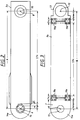
- zeigt den die Drehachsen (6,8) verbindenden Schenkel (5a) aus Figur 1 in vergrößertem Maßstabe in der Ansicht in Richtung der Tasterlängsachse;
- Figur 3
- ist eine Ansicht auf die die Drehachse (8) und die Tasterlängsachse (10) verbindenden Bauteile des KMG aus Figur 1 in vergrößertem Maßstabe, ebenfalls in Richtung der Tasterlängsachse (10).
- Figure 1
- is a simplified perspective view of the moving parts of a coordinate measuring machine with rotary axes connected in series;
- Figure 2
- shows the leg (5a) connecting the axes of rotation (6a) of Figure 1 on an enlarged scale in the view in the direction of the longitudinal axis of the button;
- Figure 3
- is a view of the components of the CMM from FIG. 1 connecting the axis of rotation (8) and the longitudinal axis of the stylus (10) on an enlarged scale, likewise in the direction of the longitudinal axis of the stylus (10).
Bei der Beschreibung der Figur 1 gehen wir aus von einem Koordinatenmeßgerät des Typs wie es beispielsweise in der eingangs genannten US-PS 5 396 712 und der dazu korrespondierenden DE 42 38 139 A1 beschrieben ist, auf die an dieser Stelle voll inhaltlich Bezug genommen wird. Nicht dargestellt in der Figur 1 sind das Maschinenbett dieses Gerätes mit dem Werkstücktisch und der vertikalen z-Säule, an der ein gabelförmiger Träger (4) aus Stahl motorisch in Richtung des mit (Z1) bezeichneten Pfeils vertikal nachgeführt werden kann.In the description of FIG. 1, we start from a coordinate measuring machine of the type described, for example, in the aforementioned US Pat. No. 5,396,712 and the corresponding DE 42 38 139 A1, to which reference is made in full at this point. Not shown in FIG. 1 are the machine bed of this device with the workpiece table and the vertical z-column, on which a fork-shaped support (4) made of steel can be moved vertically in the direction of the arrow labeled (Z1).
In die beiden Schenkel des Trägers (4) sind die Lager für eine die Schenkel verbindende Welle (14) eingesetzt, die eine erste vertikale Drehachse (6) definiert. Um diese Achse (6) läßt sich wie durch den Pfeil (X) angedeutet ein an der Welle (14) befestigter erster Arm (5) in der Waagerechten verschwenken. Das zur Erfassung der Schwenkbewegung erforderliche Winkelmeßsystem ist hier der Übersichtlichkeit halber nicht dargestellt. Der Schwenkarm (5) ist ebenfalls gabelförmig ausgebildet, wobei die Enden der Zinken (5a) und (5b) des gabelförmigen Schwenkarms wieder die Lager für eine zweite Welle (15) tragen. Diese Welle definiert die zweite Drehachse (8), die einen Abstand (A) zur ersten Drehachse (6) besitzt und zu dieser parallel ausgerichtet ist. Um die Achse (8) ist ein an der Welle (15) befestigter zweiter Schwenkarm wie durch den Pfeil (Y) veranschaulicht drehbar. Dieser zweite Schwenkarm besteht aus drei Teilen und ist in Form eines Federparallelogrammes ausgebildet, um den an seinem vorderen Ende angeordneten Träger (13) für den Taster des Gerätes manuell in der Vertikalen auslenken zu können, wie das durch den Pfeil (Z2) angedeutet ist. Der Taster trägt an seiner Unterseite einen nachgiebig gelagerten Taststift (11) mit Tastkugel (12).The bearings for a shaft (14) connecting the legs, which defines a first vertical axis of rotation (6), are inserted into the two legs of the carrier (4). As indicated by the arrow (X), a first arm (5) attached to the shaft (14) can be pivoted horizontally about this axis (6). The angle measuring system required to detect the swiveling movement is not shown here for the sake of clarity. The swivel arm (5) is also fork-shaped, the ends of the prongs (5a) and (5b) of the fork-shaped swivel arm again supporting the bearings for a second shaft (15). This shaft defines the second axis of rotation (8), which is at a distance (A) from the first axis of rotation (6) and is aligned parallel to the latter. A second swivel arm attached to the shaft (15) can be rotated about the axis (8) as illustrated by the arrow (Y). This second swivel arm consists of three parts and is designed in the form of a spring parallelogram in order to be able to manually deflect the vertical support (13) for the pushbutton of the device, as indicated by the arrow (Z2). The button has a resiliently mounted stylus (11) with a stylus ball (12) on its underside.
Realisiert ist das Federparallelogramm durch zwei parallel angeordnete Schenkel (9a) und (9b), deren Enden durch je vier paarweise nebeneinander liegende Gelenkfedern (19a) und (19b) einmal mit der Ober- bzw. Unterseite des Trägers (13) und einmal mit dem Teil (7) verbunden sind, das zwischen den Schenkeln (5a) und (5b) des ersten Schwenkarms an der Welle (15) gelagert ist.The spring parallelogram is realized by two legs (9a) and (9b) arranged in parallel, the ends of which are connected by four joint springs (19a) and (19b) lying next to each other in pairs, once with the top and bottom of the carrier (13) and once with the Part (7) are connected, which is mounted on the shaft (15) between the legs (5a) and (5b) of the first swivel arm.
Für das koordinatenmäßige Vermessen von Werkstücken mit diesem Gerät ist es nun besonders wichtig, daß die Abstände (A) und (B) zwischen den beiden Drehachsen (6) und (8) sowie der Drehachse (8) und der Taststiftlängsachse (10) während des Meßbetriebs konstant bleiben, da von diesen Längen die möglichst genau zu berechnende Position der Tastkugel (12) abhängt. Um das auch für einen größeren Temperaturbereich zu gewährleisten, sind folgende Maßnahmen ergriffen worden:For the coordinate measurement of workpieces with this device, it is now particularly important that the distances (A) and (B) between the two axes of rotation (6) and (8) and the axis of rotation (8) and the longitudinal axis of the stylus (10) during Measuring operation remain constant, since the position of the probe ball (12) to be calculated as precisely as possible depends on these lengths. The following measures have been taken to ensure that this also applies to a larger temperature range:
Wie aus der vergrößerten Aufsicht auf die Unterseite des ersten Schwenkarms (5) hervorgeht, besteht der Schenkel (5a) des Schwenkarms aus Kohlefaserverstärktem Kunststoff (CFK), dessen Fasern so liegen bzw. ausgerichtet sind, daß sich in Richtung der die Achsen (6,8) verbindenden Strecke (A) ein thermischer Ausdehnungskoeffizient ![]()
![]()
Das Teil (14a), mit dem die Welle (14) an dem CFK-Teil (5a) befestigt ist, besteht aus Aluminium mit einem thermischen Ausdehnungskoeffizienten von 24 · 10-6 K-1 und trägt effektiv mit einer Länge L3 = 5,2 mm zur thermischen Längenausdehnung bei. Am anderen Ende des Teils (5a) sind die Lager für die Welle (15) eingesetzt, die aus Keramikmaterial besteht, das aber an dieser Stelle was den Abstand (A) zwischen den Achsen (6) und (8) bzw. deren thermische Längenausdehnung anbetrifft jedoch nicht zu berücksichtigen ist, da der Lagermittelpunkt unabhängig von der Materialart von Lager und Welle zentrisch bleibt.The part (14a) with which the shaft (14) is attached to the CFRP part (5a) is made of aluminum with a thermal expansion coefficient of 24 · 10 -6 K -1 and effectively has a length L3 = 5, 2 mm to the thermal linear expansion at. At the other end of part (5a) the bearings for the shaft (15) are used, which consists of ceramic material, but at this point what the distance (A) between the axes (6) and (8) or their thermal linear expansion However, this does not have to be taken into account, since the center of the bearing remains centric regardless of the material type of the bearing and shaft.
Für die thermische Längendehnung l1' des Abstands (A) ergibt sich deshalb:![]()
![]()
![]()
![]()
Daraus ist ersichtlich, daß sich der Abstand (A) selbst über einen Temperaturbereich von 30 K nur um ca. 0,16µm ändert. Diese geringfügige Änderung ist im Rahmen der Meßgenauigkeit des in Figur 1 dargestellten Gerätes völlig vernachlässigbar.From this it can be seen that the distance (A) only changes by approx. 0.16 µm over a temperature range of 30 K. This slight change is completely negligible within the measuring accuracy of the device shown in FIG. 1.
Beim zweiten, in Figur 3 skizzierten Gelenkarm sind die Verhältnisse ähnlich. Hier ist der thermische Ausdehnungskoeffizient α4 der Welle (15) aus Keramikmaterial zu berücksichtigen, der 1,5 · 10-6 K-1 beträgt. Das Teil (7), das die Welle (15) umgibt, besteht ebenfalls aus diesem Keramikmaterial. Für die thermische Längenausdehnung des Abstands (B) zwischen der Drehachse (8) und der Tasterachse (10) ist für das Teil (7) der Abstand L4 zwischen dem Mittelpunkt der Welle (15) und den Befestigungspunkten der Biegefedern (19a) am Teil (7) zu berücksichtigen. Dieser Abstand L4 beträgt 23,6 mm. Der Tasterhalter (13) besteht ebenfalls aus diesem Keramikmaterial und besitzt eine effektive, für die thermische Ausdehnung zu berücksichtigende Länge L14 von 20,5 mm.The situation is similar in the second articulated arm sketched in FIG. 3. Here the thermal expansion coefficient α4 of the shaft (15) made of ceramic material must be taken into account, which is 1.5 · 10 -6 K -1 . The part (7) which surrounds the shaft (15) is also made of this ceramic material. For the thermal linear expansion of the distance (B) between the axis of rotation (8) and the feeler axis (10), the distance L4 between the center of the shaft (15) and the fastening points of the spiral springs (19a) on the part (7) 7) to be considered. This distance L4 is 23.6 mm. The button holder (13) also consists of this ceramic material and has an effective length L14 of 20.5 mm to be taken into account for the thermal expansion.
Die beiden Schenkel (9a) und (9b) des Federparallelogramms bestehen wieder aus dem Material CFK mit einen negativem thermischen Ausdehnungskoeffizienten von -0,8 · 10-6 K-1 in Richtung der Strecke (B). Die zu berücksichtigende Länge L11 beträgt 186 mm.The two legs (9a) and (9b) of the spring parallelogram again consist of the material CFRP with a negative coefficient of thermal expansion of -0.8 · 10 -6 K -1 in the direction of the path (B). The length L11 to be taken into account is 186 mm.
Einen Beitrag liefern nun noch die Stahlfedern (19a) und (19b) mit ihrer effektiven Länge L12 von je 10 mm zwischen den Befestigungspunkten.The steel springs (19a) and (19b) with their effective length L12 of 10 mm each between the fastening points also make a contribution.
Damit ergibt sich für die thermische Dehnung l2' des zweiten Gelenkarms:![]()
![]()
Mit den für dieses Beispiel maßgeblichen Werten erhält man![]()
![]()
Über einen Temperaturbereich von 30 K beträgt hier die thermische Dehnung der Strecke (B) zwischen der Drehachse (8) und der Tasterachse (10) insgesamt 2,86µm, was im Rahmen der Meßgenauigkeit des Geräts ebenfalls noch vernachlässigbar ist. Ein noch etwas besseres Ergebnis läßt sich durch Verkürzen der Biegefedern (19) aus Stahl bzw. Verlängern der CFK-Teile (9a/9b) erreichen.Over a temperature range of 30 K, the thermal expansion of the distance (B) between the axis of rotation (8) and the probe axis (10) is 2.86 µm in total, which is also negligible within the measuring accuracy of the device. An even better result can be achieved by shortening the steel springs (19) or lengthening the CFRP parts (9a / 9b).
Das die beiden Schenkel (5a) und (5b) verbindende Mittelteil des ersten Schwenkarms (5) besteht ebenfalls aus CFK, allerdings ist dieses Mittelteil bezüglich der Lage der den Kunststoff verstärkenden Kohlefasern so gewickelt, daß sich bei gleichzeitiger guter Stabilität des Teils in Richtung der ersten Schwenkachse (6) ein positiver thermischer Ausdehnungskoeffizient α1' von ca. +1 · 10-6/K ergibt. Damit besitzt der Abstand der die beiden Lager für die Welle (15) tragenden Schenkel (5a) und (5b) des ersten Schwenkarms größenordnungsmäßig das gleiche thermische Ausdehnungsverhalten wie die Welle (15) aus Keramikmaterial, so daß auch an dieser Stelle keine zerstörenden Kräfte infolge thermischer Ausdehnung auf die Lager der Welle (15) ausgeübt werden.The middle part of the first swivel arm (5) connecting the two legs (5a) and (5b) is also made of CFRP, but this middle part is wound with respect to the position of the plastic reinforcing carbon fibers in such a way that with simultaneous good stability of the part in the direction of the first pivot axis (6) results in a positive thermal expansion coefficient α1 'of approx. +1 · 10 -6 / K. Thus, the distance between the two bearings for the shaft (15) supporting legs (5a) and (5b) of the first swivel arm is of the same order of magnitude the same thermal expansion behavior as the shaft (15) made of ceramic material, so that no destructive forces result at this point either thermal expansion can be exerted on the bearings of the shaft (15).
Claims (5)
Applications Claiming Priority (2)
| Application Number | Priority Date | Filing Date | Title |
|---|---|---|---|
| DE19534425 | 1995-09-16 | ||
| DE19534425A DE19534425A1 (en) | 1995-09-16 | 1995-09-16 | Coordinate measuring device, the probe of which is movably supported over several axes of rotation |
Publications (3)
| Publication Number | Publication Date |
|---|---|
| EP0763709A2 true EP0763709A2 (en) | 1997-03-19 |
| EP0763709A3 EP0763709A3 (en) | 1998-07-01 |
| EP0763709B1 EP0763709B1 (en) | 2002-10-30 |
Family
ID=7772378
Family Applications (1)
| Application Number | Title | Priority Date | Filing Date |
|---|---|---|---|
| EP96113891A Expired - Lifetime EP0763709B1 (en) | 1995-09-16 | 1996-08-30 | Coordinate measuring machine with a measuring head movable about several axes |
Country Status (4)
| Country | Link |
|---|---|
| US (1) | US5890300A (en) |
| EP (1) | EP0763709B1 (en) |
| JP (1) | JP3684000B2 (en) |
| DE (2) | DE19534425A1 (en) |
Cited By (1)
| Publication number | Priority date | Publication date | Assignee | Title |
|---|---|---|---|---|
| WO2022140748A1 (en) * | 2020-12-24 | 2022-06-30 | Sa08700334 | Ultra-light and ultra-accurate portable coordinate measurement machine substantially immune to bearing assembly thermal effects |
Families Citing this family (12)
| Publication number | Priority date | Publication date | Assignee | Title |
|---|---|---|---|---|
| JP3633788B2 (en) * | 1998-07-13 | 2005-03-30 | 株式会社ミツトヨ | measuring device |
| US6253458B1 (en) * | 1998-12-08 | 2001-07-03 | Faro Technologies, Inc. | Adjustable counterbalance mechanism for a coordinate measurement machine |
| USD423534S (en) * | 1999-02-19 | 2000-04-25 | Faro Technologies, Inc. | Articulated arm |
| US6298572B1 (en) | 2000-01-10 | 2001-10-09 | Mcauley Brian | Universal holding device for effectuating three dimensional measurement of a part and method of constructing such a holding device |
| DE50207022D1 (en) * | 2001-07-16 | 2006-07-06 | Werth Messtechnik Gmbh | COORDINATE MEASURING DEVICE WITH ADDITIONAL HEAT SOURCE |
| GB0324519D0 (en) * | 2003-10-21 | 2003-11-26 | Renishaw Plc | Metrology instruments |
| WO2008066896A2 (en) * | 2006-11-30 | 2008-06-05 | Faro Technologies, Inc. | Portable coordinate measurement machine |
| JP5270384B2 (en) * | 2009-01-15 | 2013-08-21 | 株式会社ミツトヨ | Linear guide mechanism and measuring device |
| WO2016135204A1 (en) * | 2015-02-26 | 2016-09-01 | Marposs Societa' Per Azioni | System for checking dimensional and/or geometric features of workpieces, and relative procedure for manufacturing |
| EP4265231A3 (en) | 2015-08-14 | 2023-12-20 | Alcon Inc. | Ocular implant with pressure sensor |
| US11566880B2 (en) * | 2017-04-13 | 2023-01-31 | Sa08700334 | Ultra-light and ultra-accurate portable coordinate measurement machine substantially immune to bearing assembly thermal effects |
| JP7203312B2 (en) * | 2020-04-30 | 2023-01-13 | 株式会社東京精密 | measuring device |
Citations (3)
| Publication number | Priority date | Publication date | Assignee | Title |
|---|---|---|---|---|
| US4282688A (en) * | 1979-07-05 | 1981-08-11 | The Perkin-Elmer Corporation | Adjustable CTE graphite-epoxy bar |
| US4815213A (en) * | 1987-10-09 | 1989-03-28 | Brown & Sharpe Manufacturing Co. | Apparatus for temperature compensation of sensing means of a machine |
| US5095632A (en) * | 1990-06-15 | 1992-03-17 | Parker Hannifin Corporation | Composite structure unidirectionally stable with respect to thermal and moisture expansion |
Family Cites Families (8)
| Publication number | Priority date | Publication date | Assignee | Title |
|---|---|---|---|---|
| US3077958A (en) * | 1961-09-05 | 1963-02-19 | United Aircraft Corp | Zero thermal expansion device |
| GB1059167A (en) * | 1962-10-18 | 1967-02-15 | Sogenique Service Ltd | Improvements in and relating to metrological apparatus |
| US3311986A (en) * | 1964-08-07 | 1967-04-04 | Technion Res & Dev Foundation | Compensated gauges for external dimensions |
| US3528206A (en) * | 1967-08-03 | 1970-09-15 | Canadian Patents Dev | Thermal expansion compensation device |
| US4761887A (en) * | 1986-08-29 | 1988-08-09 | Control Gaging, Inc. | Temperature insensitive gauge |
| DE3711070A1 (en) * | 1987-04-02 | 1988-11-24 | Heidenhain Gmbh Dr Johannes | LENGTH OR ANGLE MEASURING DEVICE |
| DE4238139C2 (en) * | 1992-11-12 | 2002-10-24 | Zeiss Carl | The coordinate |
| US5402582A (en) * | 1993-02-23 | 1995-04-04 | Faro Technologies Inc. | Three dimensional coordinate measuring apparatus |
-
1995
- 1995-09-16 DE DE19534425A patent/DE19534425A1/en not_active Withdrawn
-
1996
- 1996-08-30 EP EP96113891A patent/EP0763709B1/en not_active Expired - Lifetime
- 1996-08-30 DE DE59609831T patent/DE59609831D1/en not_active Expired - Fee Related
- 1996-09-13 JP JP24364696A patent/JP3684000B2/en not_active Expired - Fee Related
- 1996-09-13 US US08/713,501 patent/US5890300A/en not_active Expired - Fee Related
Patent Citations (3)
| Publication number | Priority date | Publication date | Assignee | Title |
|---|---|---|---|---|
| US4282688A (en) * | 1979-07-05 | 1981-08-11 | The Perkin-Elmer Corporation | Adjustable CTE graphite-epoxy bar |
| US4815213A (en) * | 1987-10-09 | 1989-03-28 | Brown & Sharpe Manufacturing Co. | Apparatus for temperature compensation of sensing means of a machine |
| US5095632A (en) * | 1990-06-15 | 1992-03-17 | Parker Hannifin Corporation | Composite structure unidirectionally stable with respect to thermal and moisture expansion |
Cited By (1)
| Publication number | Priority date | Publication date | Assignee | Title |
|---|---|---|---|---|
| WO2022140748A1 (en) * | 2020-12-24 | 2022-06-30 | Sa08700334 | Ultra-light and ultra-accurate portable coordinate measurement machine substantially immune to bearing assembly thermal effects |
Also Published As
| Publication number | Publication date |
|---|---|
| EP0763709B1 (en) | 2002-10-30 |
| DE59609831D1 (en) | 2002-12-05 |
| DE19534425A1 (en) | 1997-03-20 |
| JPH09113258A (en) | 1997-05-02 |
| EP0763709A3 (en) | 1998-07-01 |
| JP3684000B2 (en) | 2005-08-17 |
| US5890300A (en) | 1999-04-06 |
Similar Documents
| Publication | Publication Date | Title |
|---|---|---|
| EP0597299B1 (en) | coordinate measuring machine | |
| EP0317967B1 (en) | Rotation-deflection arrangement for the feeler heads of coordinate-measuring devices | |
| EP0763709B1 (en) | Coordinate measuring machine with a measuring head movable about several axes | |
| DE2934347C2 (en) | Method and testing device for testing the tooth flank profile of large diameter gears | |
| EP0456276A1 (en) | Coordinate measuring apparatus | |
| DE3619643C2 (en) | Pipe bending machine | |
| CH672838A5 (en) | ||
| DE4139309A1 (en) | Measuring dimensions of hollow bodies, esp. pipes - using fixed and movable parts with sensing arms with stops image separation measured when applied to pipe | |
| CH667916A5 (en) | METHOD AND MEASURING DIRECTOR FOR MEASURING STRAIGHTNESS AND FLATNESS. | |
| DE3724656C2 (en) | ||
| DE3019751C2 (en) | Device for measuring the cutting force of cutting tools in a multiple tool holder | |
| DE3717541A1 (en) | COORDINATE MEASURING DEVICE | |
| DE3512935C2 (en) | ||
| DD139454A1 (en) | PROBE | |
| DE3422161C2 (en) | ||
| DE10319947A1 (en) | Surface contour measurement device for use with rotationally symmetric workpieces comprises an optical measurement assembly with light source and sensor and an additional electromechanical feeler transducer assembly | |
| DE2346031B1 (en) | Measuring head for coordinate measuring machines | |
| DE2307824A1 (en) | ROLL MEASURING DEVICE | |
| DE3538551C1 (en) | Auxiliary reference device for, in particular, three-dimensional measurement and/or marking apparatuses | |
| CH664012A5 (en) | Method and device for measuring a werkstueckes. | |
| DE2935898C2 (en) | Rotation transducer for position measurement | |
| DE1548305B2 (en) | Device for determining the surface roughness | |
| DE19861469B4 (en) | Calibrating scanner of electronically-controlled co-ordinate measuring device | |
| DE2636645C2 (en) | Probe for length measuring machines | |
| DE154266C (en) |
Legal Events
| Date | Code | Title | Description |
|---|---|---|---|
| PUAI | Public reference made under article 153(3) epc to a published international application that has entered the european phase |
Free format text: ORIGINAL CODE: 0009012 |
|
| AK | Designated contracting states |
Kind code of ref document: A2 Designated state(s): DE FR GB IT |
|
| PUAL | Search report despatched |
Free format text: ORIGINAL CODE: 0009013 |
|
| AK | Designated contracting states |
Kind code of ref document: A3 Designated state(s): DE FR GB IT |
|
| 17P | Request for examination filed |
Effective date: 19981202 |
|
| 17Q | First examination report despatched |
Effective date: 20010704 |
|
| GRAG | Despatch of communication of intention to grant |
Free format text: ORIGINAL CODE: EPIDOS AGRA |
|
| GRAG | Despatch of communication of intention to grant |
Free format text: ORIGINAL CODE: EPIDOS AGRA |
|
| GRAH | Despatch of communication of intention to grant a patent |
Free format text: ORIGINAL CODE: EPIDOS IGRA |
|
| RAP1 | Party data changed (applicant data changed or rights of an application transferred) |
Owner name: CARL-ZEISS-STIFTUNG, TRADING AS CARL ZEISS Owner name: CARL ZEISS |
|
| GRAH | Despatch of communication of intention to grant a patent |
Free format text: ORIGINAL CODE: EPIDOS IGRA |
|
| GRAA | (expected) grant |
Free format text: ORIGINAL CODE: 0009210 |
|
| AK | Designated contracting states |
Kind code of ref document: B1 Designated state(s): DE FR GB IT |
|
| REG | Reference to a national code |
Ref country code: GB Ref legal event code: FG4D Free format text: NOT ENGLISH |
|
| REF | Corresponds to: |
Ref document number: 59609831 Country of ref document: DE Date of ref document: 20021205 |
|
| GBT | Gb: translation of ep patent filed (gb section 77(6)(a)/1977) |
Effective date: 20030120 |
|
| ET | Fr: translation filed | ||
| PLBE | No opposition filed within time limit |
Free format text: ORIGINAL CODE: 0009261 |
|
| STAA | Information on the status of an ep patent application or granted ep patent |
Free format text: STATUS: NO OPPOSITION FILED WITHIN TIME LIMIT |
|
| 26N | No opposition filed |
Effective date: 20030731 |
|
| REG | Reference to a national code |
Ref country code: GB Ref legal event code: 732E |
|
| PGFP | Annual fee paid to national office [announced via postgrant information from national office to epo] |
Ref country code: DE Payment date: 20080822 Year of fee payment: 13 |
|
| PGFP | Annual fee paid to national office [announced via postgrant information from national office to epo] |
Ref country code: IT Payment date: 20080825 Year of fee payment: 13 Ref country code: FR Payment date: 20080813 Year of fee payment: 13 |
|
| PGFP | Annual fee paid to national office [announced via postgrant information from national office to epo] |
Ref country code: GB Payment date: 20080821 Year of fee payment: 13 |
|
| GBPC | Gb: european patent ceased through non-payment of renewal fee |
Effective date: 20090830 |
|
| REG | Reference to a national code |
Ref country code: FR Ref legal event code: ST Effective date: 20100430 |
|
| PG25 | Lapsed in a contracting state [announced via postgrant information from national office to epo] |
Ref country code: FR Free format text: LAPSE BECAUSE OF NON-PAYMENT OF DUE FEES Effective date: 20090831 Ref country code: DE Free format text: LAPSE BECAUSE OF NON-PAYMENT OF DUE FEES Effective date: 20100302 |
|
| PG25 | Lapsed in a contracting state [announced via postgrant information from national office to epo] |
Ref country code: GB Free format text: LAPSE BECAUSE OF NON-PAYMENT OF DUE FEES Effective date: 20090830 |
|
| PG25 | Lapsed in a contracting state [announced via postgrant information from national office to epo] |
Ref country code: IT Free format text: LAPSE BECAUSE OF NON-PAYMENT OF DUE FEES Effective date: 20090830 |