EP0763437A1 - Tyre-pressure surveillance device - Google Patents
Tyre-pressure surveillance device Download PDFInfo
- Publication number
- EP0763437A1 EP0763437A1 EP96114843A EP96114843A EP0763437A1 EP 0763437 A1 EP0763437 A1 EP 0763437A1 EP 96114843 A EP96114843 A EP 96114843A EP 96114843 A EP96114843 A EP 96114843A EP 0763437 A1 EP0763437 A1 EP 0763437A1
- Authority
- EP
- European Patent Office
- Prior art keywords
- antenna
- receiver
- switches
- signal
- field strength
- Prior art date
- Legal status (The legal status is an assumption and is not a legal conclusion. Google has not performed a legal analysis and makes no representation as to the accuracy of the status listed.)
- Granted
Links
Images
Classifications
-
- B—PERFORMING OPERATIONS; TRANSPORTING
- B60—VEHICLES IN GENERAL
- B60C—VEHICLE TYRES; TYRE INFLATION; TYRE CHANGING; CONNECTING VALVES TO INFLATABLE ELASTIC BODIES IN GENERAL; DEVICES OR ARRANGEMENTS RELATED TO TYRES
- B60C23/00—Devices for measuring, signalling, controlling, or distributing tyre pressure or temperature, specially adapted for mounting on vehicles; Arrangement of tyre inflating devices on vehicles, e.g. of pumps or of tanks; Tyre cooling arrangements
- B60C23/02—Signalling devices actuated by tyre pressure
- B60C23/04—Signalling devices actuated by tyre pressure mounted on the wheel or tyre
- B60C23/0408—Signalling devices actuated by tyre pressure mounted on the wheel or tyre transmitting the signals by non-mechanical means from the wheel or tyre to a vehicle body mounted receiver
- B60C23/0415—Automatically identifying wheel mounted units, e.g. after replacement or exchange of wheels
- B60C23/0416—Automatically identifying wheel mounted units, e.g. after replacement or exchange of wheels allocating a corresponding wheel position on vehicle, e.g. front/left or rear/right
-
- B—PERFORMING OPERATIONS; TRANSPORTING
- B60—VEHICLES IN GENERAL
- B60C—VEHICLE TYRES; TYRE INFLATION; TYRE CHANGING; CONNECTING VALVES TO INFLATABLE ELASTIC BODIES IN GENERAL; DEVICES OR ARRANGEMENTS RELATED TO TYRES
- B60C23/00—Devices for measuring, signalling, controlling, or distributing tyre pressure or temperature, specially adapted for mounting on vehicles; Arrangement of tyre inflating devices on vehicles, e.g. of pumps or of tanks; Tyre cooling arrangements
- B60C23/02—Signalling devices actuated by tyre pressure
- B60C23/04—Signalling devices actuated by tyre pressure mounted on the wheel or tyre
- B60C23/0408—Signalling devices actuated by tyre pressure mounted on the wheel or tyre transmitting the signals by non-mechanical means from the wheel or tyre to a vehicle body mounted receiver
- B60C23/0422—Signalling devices actuated by tyre pressure mounted on the wheel or tyre transmitting the signals by non-mechanical means from the wheel or tyre to a vehicle body mounted receiver characterised by the type of signal transmission means
- B60C23/0433—Radio signals
- B60C23/0435—Vehicle body mounted circuits, e.g. transceiver or antenna fixed to central console, door, roof, mirror or fender
- B60C23/0444—Antenna structures, control or arrangements thereof, e.g. for directional antennas, diversity antenna, antenna multiplexing or antennas integrated in fenders
Definitions
- the present invention relates to a tire pressure monitoring device according to the preamble of claim 1. Furthermore, the invention relates to a multiple receiver (multi-path receiver or diversity receiver), in particular a four-way receiver or five-way receiver for such a tire pressure monitoring device.
- the tire pressure monitoring device according to the invention can be used on all land and aircraft which are equipped with several pneumatic tires.
- the tire pressure monitoring device according to the invention is preferably used to monitor the pressure in the tires of motor vehicles such as cars, trucks and buses. Without being limited to this, the tire pressure monitoring device according to the invention is described below in connection with a car that is equipped with four monitored wheels. Optionally, the air pressure in the spare wheel could also be monitored.
- a tire pressure monitoring device of this type is known from document DE-C2-39 30 479.
- each bike with its transmitter is assigned its own receiver.
- Each receiver typically has a ferrite rod with a receiving antenna and a known receiver circuit.
- the receiver circuit is powered by the vehicle's power source.
- the outputs of the receiver circuit are connected to a connecting cable Display device connected to the dashboard or the like of the vehicle.
- the display device includes evaluation electronics which assign the impulses coming from a specific transmitter / receiver to the associated wheel display.
- the coupling between a transmitter on the wheel and the assigned receiving antenna with receiver circuit takes place solely through the spatial assignment of this receiving antenna to the monitored wheel.
- this coupling alone has often proven to be insufficient.
- the transmitter is located on the rotating wheel, often shielded by the rim and jacket of the pneumatic tire.
- the wheel rotation can cause insufficient reception conditions, for example, signal cancellations can occur due to cancellations and / or reflections at the location of the receiving antenna.
- secure signal transmission requires such a high signal strength that the radio telegram generated by a transmitter is not only received by the immediately adjacent and assigned receiving antenna, but also by the other receiving antennas on the vehicle. After all, it is time-consuming to assign a complete receiver to each wheel.
- Document DE-C2-36 05 097 relates to a device for determining measured values on wheel sets of vehicles, in particular of aircraft.
- the length of the connecting line between the sensor on the wheel and a central computer used for evaluation can be up to 30 m; therefore the number of lines should be kept as low as possible.
- a pressure signal is fed into the connecting line with the aid of a rotary transformer, the secondary winding of which is assigned to a rotating wheel section and the primary winding of which is assigned to an adjacent fixed wheel section. At any given time, only one connection line will be used Supply current led and the measurement signal transmitted.
- the temperature signal is transmitted via a "wrong" line that is not activated at this time. From this "wrong" line, the temperature signal is reassigned to the currently activated wheel with the aid of a multiplexing means.
- the temperature signal is reassigned to the currently activated wheel with the aid of a multiplexing means.
- the document DE-A1-42 05 911 discloses a control device for the air pressure of pneumatic vehicle wheels.
- the signal is transmitted telemetrically from each rotating wheel to, for example, a central receiving device.
- the pressure signals are provided with an identification signal which is characteristic of the respective wheel.
- the receiving device is provided with a memory in which these identification signals are stored in relation to the wheel.
- the associated wheel is determined via the identity of a identification signal transmitted and received telemetrically with the stored identification signal.
- a multiplexer circuit is not mentioned in connection with the known receiving device.
- the object of the present invention is to provide a simply constructed receiving and evaluating device for a tire pressure monitoring device of this type, which enables a radio telegram to be reliably assigned to the transmitted wheel, so that the vehicle driver assigns the measured values or warnings to the correct one Wheel position can be communicated.
- the highest possible through multipath reception via at least four antennas Transmission security of the radio telegrams can be guaranteed.
- a simply constructed multiple receiver in particular a four-way receiver or a five-way receiver, is to be provided for such a tire pressure monitoring device.
- the device according to the invention requires only a single receiver. For a car with four active wheels and consequently four receiving antennas on the vehicle, only a single receiver is required. Compared to the tire pressure monitoring device mentioned at the beginning, known from DE-C2-39 50 479, three receivers can thus be saved.
- the invention ensures a reliable assignment of a radio telegram to the transmitting wheel, and at the same time a high transmission security of the radio telegram through multi-path reception.
- the assignments between radio telegram and associated wheel position are averaged over a longer period of time (at least several consecutive radio telegrams of a specific wheel), so that the accuracy of the assignment of radio telegram to radio telegram is increased.
- this embodiment of the invention provides a simply constructed multiple receiver for a tire pressure monitoring device of this type.
- the present invention is primarily concerned with the receiving devices on the vehicle.
- Known components are used for the transmitter-side components on the wheel, such as a signal generating device, transmitting device and the like.
- These transmitter-side components can be located, for example, on a tire valve, as described in documents DE-C2-39 30 479 or DE-C2-43 03 583. Can continue the transmitter-side components are located on a valve cap which can be screwed onto the valve tube of a conventional tire valve of a vehicle tire, as described in documents DE-C2-39 30 480 or DE-C2-43 03 591.
- these transmitter-side components can also be fastened to the fig of a vehicle wheel, as is described in further publications. It is important that these transmitter-side components generate a radio telegram in the form of an RF signal on the rotating vehicle wheel, which at least contains useful signals which indicate the most important current state variables of the pneumatic tire, in particular the tire pressure and possibly the tire temperature.
- the radio telegram is typically a modulated RF signal in the megahertz range (MHz), for example frequencies above 200 MHz, preferably frequencies around 433 MHz or around 900 MHz, can be provided.
- the data to be transmitted are preferably in digital form, and amplitude modulation or frequency modulation of the carrier frequency can be provided.
- a preferred radio telegram in digital form can comprise approximately 60 to 80 bits.
- Such a radio telegram can have a synchronization signal (approximately 8 to 16 bits), an identifier (typically 32 bits), the useful signals (approximately 4 to 16 bits) and a check digit.
- the transmission of such a radio telegram takes a few microseconds to a few milliseconds.
- the transmission of a radio telegram comprising approximately 80 bits takes approximately 5 msec.
- a reception antenna is assigned to each wheel with its transmitter.
- This receiving antenna is fixed to the vehicle adjacent to the wheel, for example in the area of the respective wheel arch.
- This receiving antenna is in a known manner for receiving RF signals from the wheel electronics to optimize. These signals are demodulated and decoded in the receiver and the evaluation device.
- the receiver can preferably be designed for a sensitivity of minus 100 to minus 120 dBm.
- a reception and evaluation device is located at a central point in the vehicle.
- This receiving and evaluating device can be combined into a single unit and then comprises the actual receiver, as well as an evaluating device in the form of a control device or microprocessor with the various switching devices (decoding) and logic elements.
- a multiplexer circuit also belongs to these switching devices.
- This unit can be accommodated in the trunk of a vehicle, for example. Lines can then lead from this unit for signal transmission to the dashboard or to the interface of an on-board computer of the vehicle.
- a single receiver can be provided, which is connected via lines to a spatially separated evaluation device.
- each receiving antenna (hereinafter referred to as "antenna”) has its own connection line to the receiver.
- these connecting lines can have a different length, which can lead to a correspondingly different attenuation of the signals transmitted via the connecting line.
- the measured field strengths are additionally evaluated (microprocessor) in order to compensate for such device-related damping. It is typically not necessary in the context of the invention to provide amplifiers on the way from the antenna to the receiver.
- a switch is inserted in each connecting line.
- diodes or transistors are preferably provided as switches.
- Each switch is controlled by the multiplexer circuit in a time-division multiplexing process and is thus put into a blocking state or a transmission state.
- a multiplexer circuit particularly suitable for the present invention typically comprises a microprocessor in order to control these switches in a suitable manner.
- a multiplexer circuit is preferably provided within the scope of the present invention, which can put several switches or all switches into the on state at the same time.
- each antenna can be queried in sequence using the time-division multiplex method and the respectively applied field strength can be determined, stored and compared with one another in order to determine the antenna to which the greatest field strength is applied.
- the invention is not limited to a specific method for determining the antenna with the greatest field strength.
- the receiver can approach the maximum received signal with every bit period without losing a data bit, since the reception conditions improve with each selection.
- the resulting wheel assignment can still be verified and corrected until the last bit of a radio telegram. For this further verification, this can also be done for each wheel and its transmitter characteristic identification signal, with which each radio telegram is preferably additionally equipped. The probability of a misinterpretation thus drops from bit to bit within a radio telegram and from one radio telegram to the next radio telegram.
- a high number of components and with a minimum number of radio telegrams is used to achieve high accuracy when assigning a radio telegram to the "transmitting wheel".
- the method explained above for selecting the antenna with the greatest field strength can be carried out for the entire duration of a radio telegram. However, this selection is preferably carried out only during the duration of the synchronization signal of a radio telegram.
- a synchronization signal can comprise, for example, 8 to 16 bits.
- This synchronization signal does not yet contain any data information with regard to the useful signals. Even if some bits of the synchronization signal are lost in the course of the selection process, an appropriate wheel assignment can be made. In this case, the decoding and evaluation of the useful signals can be carried out after the assignment of the radio telegram to a specific wheel has been established.
- the multiplexer circuit at a given point in time during the reception of a radio telegram only puts a single switch or only two switches into the on state and at a later point in time during the reception of the same radio telegram several switches or all switches simultaneously placed in the on state.
- antennas are continuously switched off during the evaluation of the synchronization signal until the antenna with the greatest field strength is determined.
- the multiplexer circuit during transmission of a synchronizing signal of a radio telegram successively puts only one switch or only two switches into the pass state until the antenna with the greatest field strength is selected; and the multiplexer circuit during the subsequent transmission of the useful signal of this radio telegram puts several switches or all switches in the on state in order to to achieve multiple reception of this useful signal via several antennas.
- a circuit diagram is also used to further explain the invention, with which the structure of a multiple receiver preferred according to the invention is shown schematically.
- a receiving and evaluating device preferred according to the invention can, for example, have a structure as shown in the single circuit diagram.
- Four receiving antennas A, B, C, N are provided for a vehicle, for example a car with four active wheels.
- a connecting line a, b, c, n leads from each antenna A, B, C, N to a summing point S.
- a diode acting as a switch or a transistor acting as a switch is inserted into each connecting line a, b, c, n.
- the receiver and evaluation device is provided with a microcontroller, which in turn is equipped with an input multiplexer circuit.
- a control line a ', b', c ', n' leads from the microcontroller to the associated connecting line a, b, c, n in order to control the respective switch and to put it either in the blocking state or in the forward state.
- the microcontroller can thus register which antenna is connected to the summing point at a given time.
- the summing point is connected to the receiver via a filter.
- the field strength that is present at the summing point at a specific point in time is also recorded.
- the field strength initially determined in analog form is converted into a digital field strength signal with the aid of an analog / digital converter and fed to the microcontroller for evaluation.
- the useful signals are fed to the microcontroller and evaluated via a data signal line.
Landscapes
- Engineering & Computer Science (AREA)
- Mechanical Engineering (AREA)
- Arrangements For Transmission Of Measured Signals (AREA)
- Measuring Fluid Pressure (AREA)
Abstract
Description
Die vorliegende Erfindung betrifft eine Reifendruck-Überwachungseinrichtung nach dem Oberbegriff des Anspruches 1. Weiterhin betrifft die Erfindung einen Mehrfachempfänger (Multi-path Receiver oder Diversity Receiver), insbesondere einen Vierfachempfänger bzw. Fünffachempfänger für eine solche Reifendruck-Überwachungseinrichtung. Die erfindungsgemäße Reifendruck-Überwachungseinrichtung kann an sämtlichen Land- und Luftfahrzeugen eingesetzt werden, die mit mehreren Luftreifen ausgerüstet sind. Vorzugsweise dient die erfindungsgemäße Reifendruck-Überwachungseinrichtung zur Überwachung des Drucks in den Reifen von Kraftfahrzeugen wie Pkw, Lkw und Omnibussen. Ohne darauf beschränkt zu sein, wird die erfindungsgemäße Reifendruck-Überwachungseinrichtung nachstehend in Verbindung mit einem Pkw beschrieben, der mit vier überwachten Rädern ausgerüstet ist. Wahlweise könnte zusätzlich auch der Luftdruck im Ersatzrad überwacht werden.The present invention relates to a tire pressure monitoring device according to the preamble of claim 1. Furthermore, the invention relates to a multiple receiver (multi-path receiver or diversity receiver), in particular a four-way receiver or five-way receiver for such a tire pressure monitoring device. The tire pressure monitoring device according to the invention can be used on all land and aircraft which are equipped with several pneumatic tires. The tire pressure monitoring device according to the invention is preferably used to monitor the pressure in the tires of motor vehicles such as cars, trucks and buses. Without being limited to this, the tire pressure monitoring device according to the invention is described below in connection with a car that is equipped with four monitored wheels. Optionally, the air pressure in the spare wheel could also be monitored.
Eine Reifendruck-Überwachungseinrichtung dieser Art ist aus dem Dokument DE-C2-39 30 479 bekannt. Dort ist jedem Rad mit seinem Sender ein eigener Empfänger zugeordnet. Zu jedem Empfänger gehört typischerweise ein Ferritstab mit einer Empfangsantenne und einer bekannten Empfängerschaltung. Die Stromversorgung der Empfängerschaltung erfolgt über die Stromversorgungsquelle des Fahrzeugs. Die Ausgänge der Empfängerschaltung sind über Verbindungsleitungen mit einer Anzeigeeinrichtung am Armaturenbrett oder dergleichen des Fahrzeugs verbunden. Zur Anzeigeeinrichtung gehört eine Auswerteelektronik, welche die von einem bestimmten Sender/Emfänger stammenden Impulse der zugehörigen Radanzeige zuordnet.A tire pressure monitoring device of this type is known from document DE-C2-39 30 479. There, each bike with its transmitter is assigned its own receiver. Each receiver typically has a ferrite rod with a receiving antenna and a known receiver circuit. The receiver circuit is powered by the vehicle's power source. The outputs of the receiver circuit are connected to a connecting cable Display device connected to the dashboard or the like of the vehicle. The display device includes evaluation electronics which assign the impulses coming from a specific transmitter / receiver to the associated wheel display.
Bei der bekannten Reifendruck-Überwachungseinrichtung erfolgt die Koppelung zwischen einem Sender am Rad und der zugeordneten Empfangsantenne mit Empfängerschaltung allein durch die räumliche Zuordnung dieser Empfangsantenne zu dem überwachten Rad. In der Praxis hat sich allein diese Kopplung häufig als nicht ausreichend erwiesen. Der Sender befindet sich an dem sich drehenden Rad, häufig abgeschirmt durch Felge und Mantel des Luftreifens. Die Raddrehung kann ungenügende Empfangsbedingungen verursachen, beispielsweise können durch Auslöschungen und/oder Reflexionen am Ort der Empfangsantenne Signalauslöschungen auftreten. Weiterhin erfordert eine sichere Signalübermittlung eine solch hohe Signalstärke, daß das von einem Sender erzeugte Funktelegramm nicht nur von der unmittelbar benachbarten und zugeordneten Empfangsantenne aufgefangen wird, sondern auch von den anderen Empfangsantennen am Fahrzeug. Schließlich ist es aufwendig, jedem Rad einen vollständigen Empfänger zuzuordnen.In the known tire pressure monitoring device, the coupling between a transmitter on the wheel and the assigned receiving antenna with receiver circuit takes place solely through the spatial assignment of this receiving antenna to the monitored wheel. In practice, this coupling alone has often proven to be insufficient. The transmitter is located on the rotating wheel, often shielded by the rim and jacket of the pneumatic tire. The wheel rotation can cause insufficient reception conditions, for example, signal cancellations can occur due to cancellations and / or reflections at the location of the receiving antenna. Furthermore, secure signal transmission requires such a high signal strength that the radio telegram generated by a transmitter is not only received by the immediately adjacent and assigned receiving antenna, but also by the other receiving antennas on the vehicle. After all, it is time-consuming to assign a complete receiver to each wheel.
Das Dokument DE-C2-36 05 097 betrifft eine Vorrichtung zur Ermittlung von Meßwerten an Radsätzen von Fahrzeugen, insbesondere von Flugzeugen. Bei einem Großflugzeug kann die Länge der Verbindungsleitung zwischen Sensor am Rad und einem der Auswertung dienenden Zentralrechner bis zu 30 m betragen; deswegen soll die Anzahl der Leitungen möglichst gering gehalten werden. Die Einspeisung eines Drucksignales in die Verbindungsleitung erfolgt mit Hilfe eines Drehtransformators, dessen Sekundärwicklung einem drehenden Radabschnitt zugeordnet ist, und dessen Primärwicklung einem benachbarten feststehenden Radabschnitt zugeordnet ist. Zu einem gegebenen Zeitpunkt wird nur über eine einzige Verbindungsleitung Versorgungsstrom geführt und das Meßsignal übermittelt. Um zusätzlich zu dem Reifendruck auch noch die Bremstemperatur eines gegebenen Rades übermitteln zu können, erfolgt die Übermittlung des Temperatursignais über eine zu diesem Zeitpunkt nicht aktivierte "falsche" Leitung. Aus dieser "falschen" Leitung wird das Temperatursignal mit Hilfe eines Multiplexierungsmittels wieder dem gerade aktivierten Rad zugeordnet. Bei dem bekannten System erfolgt keine telemetrische Signalübermittelung, und es besteht nicht das Problem, eine Auswahl aus mehreren Drucksignalen zu treffen, die aus verschiedenen Rädern stammen und gleichzeitig an einem Empfänger anliegen.Document DE-C2-36 05 097 relates to a device for determining measured values on wheel sets of vehicles, in particular of aircraft. In the case of a large aircraft, the length of the connecting line between the sensor on the wheel and a central computer used for evaluation can be up to 30 m; therefore the number of lines should be kept as low as possible. A pressure signal is fed into the connecting line with the aid of a rotary transformer, the secondary winding of which is assigned to a rotating wheel section and the primary winding of which is assigned to an adjacent fixed wheel section. At any given time, only one connection line will be used Supply current led and the measurement signal transmitted. In order to be able to transmit the braking temperature of a given wheel in addition to the tire pressure, the temperature signal is transmitted via a "wrong" line that is not activated at this time. From this "wrong" line, the temperature signal is reassigned to the currently activated wheel with the aid of a multiplexing means. In the known system there is no telemetric signal transmission and there is no problem in making a selection from a plurality of pressure signals which originate from different wheels and which are present at the same time at a receiver.
Das Dokument DE-A1-42 05 911 offenbart eine Kontrollvorrichtung für den Luftdruck von luftbereiften Fahrzeugrädern. Die Signalübermittlung erfolgt telemetrisch von jedem drehenden Rad an beispielsweise ein zentrales Empfangsgerät. Die Drucksignale werden mit einem für das jeweilige Rad charakteristischen Identifizierungssignal versehen. Das Empfangsgerät ist mit einem Speicher versehen, in welchem diese Identifizierungssignale Rad-bezogen gespeichert sind. Über die Identität eines telemetrisch übermittelten und empfangenen Identifizierungssignals mit dem gespeicherten Identifizierungssignal wird das zugehörige Rad ermittelt. In Verbindung mit dem bekannten Empfangsgerät wird eine Multiplexerschaltung nicht erwähnt.The document DE-A1-42 05 911 discloses a control device for the air pressure of pneumatic vehicle wheels. The signal is transmitted telemetrically from each rotating wheel to, for example, a central receiving device. The pressure signals are provided with an identification signal which is characteristic of the respective wheel. The receiving device is provided with a memory in which these identification signals are stored in relation to the wheel. The associated wheel is determined via the identity of a identification signal transmitted and received telemetrically with the stored identification signal. A multiplexer circuit is not mentioned in connection with the known receiving device.
Die Aufgabe der vorliegenden Erfindung besteht darin, für eine Reifendruck-Überwachungseinrichtung dieser Art eine einfach aufgebaute Empfangs- und Auswerteeinrichtung anzugeben, die eine sichere Zuordnung eines Funktelegramms zu dem sendenen Rad ermöglicht, so daß dem Fahrzeugführer die gemessenen Werte bzw. Warnungen zugeordnet zu der richtigen Radposition mitgeteilt werden können.The object of the present invention is to provide a simply constructed receiving and evaluating device for a tire pressure monitoring device of this type, which enables a radio telegram to be reliably assigned to the transmitted wheel, so that the vehicle driver assigns the measured values or warnings to the correct one Wheel position can be communicated.
Nach einem weiteren Ziel der Erfindung soll durch Mehrwegempfang über wenigstens vier Antennen eine möglichst hohe Übertragungssicherheit der Funktelegramme gewährleistet werden.According to a further object of the invention, the highest possible through multipath reception via at least four antennas Transmission security of the radio telegrams can be guaranteed.
Nach noch einem weiteren Ziel der vorliegenden Erfindung soll ein einfach aufgebauter Mehrfachempfänger, insbesondere ein Vierfachempfänger oder Fünffachempfänger für eine solche Reifendruck-Überwachungseinrichtung bereitgestellt werden.According to yet another object of the present invention, a simply constructed multiple receiver, in particular a four-way receiver or a five-way receiver, is to be provided for such a tire pressure monitoring device.
Ausgehend von einer Reifendruck-Überwachungseinrichtung für ein Fahrzeug mit mehreren Rädern, die je mit einem Luftreifen ausgerüstet sind, mit
- einer Signalerzeugungseinrichtung an jedem Rad, welche den Luftdruck im Luftreifen und gegebenenfalls die Reifentemperatur erfaßt und entsprechende elektrische Drucksignale bzw. Temperatursignale liefert;
- je einer Empfangsantenne pro Rad, die benachbart zum jeweiligen Rad ortsfest am Fahrzeug befestigt ist;
- einer Sendeeinrichtung an jedem Rad, welche ein Funktelegramm erzeugt, das wenigstens Nutzsignale entsprechend dem elektrischen Drucksignal und gegebenenfalls dem Temperatursignal enthält, und telemetrisch an die Empfangsantenne übermittelt;
- einer zentralen Auswerteinrichtung am Fahrzeug zur Auswertung der Funktelegramme, um einen Fahrzeugführer mit Informationen über den Zustand der verschiedenen Reifen zu versorgen;
dadurch gekennzeichnet, daß
sämtlichen Empfangsantennen nur ein einziger Empfänger zugeordnet ist, der einerseits mit der Auswerteeinrichtung verbunden ist und der andererseits über je eine Verbindungleitung mit jeder Antenne verbunden ist;
diesem Empfänger eine Multiplexerschaltung zugordnet ist, mit der pro Zeiteinheit nur eine einzige ausgewählte Antenne oder gleichzeitig mehrere ausgewählte Antennen auf den Empfänger geschaltet werden;
dieser Empfänger das Funktelegramm und dessen Feldstärke erfaßt;
durch Auswertung der vom Empfänger erfaßten Feldstärken diejenige Antenne mit der größten Feldstärke selektiert wird; und
anhand dieser selektierten Antenne das Funktelegramm einem bestimmten Rad zugeordnet wird, das sich benachbart zur selektierten Antenne befindet.Starting from a tire pressure monitoring device for a vehicle with several wheels, each equipped with a pneumatic tire, with
- a signal generating device on each wheel, which detects the air pressure in the pneumatic tire and, if appropriate, the tire temperature and supplies corresponding electrical pressure signals or temperature signals;
- one receiving antenna per wheel, which is fixed to the vehicle adjacent to the respective wheel;
- a transmitting device on each wheel, which generates a radio telegram, which contains at least useful signals corresponding to the electrical pressure signal and possibly the temperature signal, and transmits them telemetrically to the receiving antenna;
- a central evaluation device on the vehicle for evaluating the radio telegrams in order to provide a vehicle driver with information about the condition of the various tires;
characterized in that
only one receiver is assigned to all of the receiving antennas, which is connected on the one hand to the evaluation device and on the other hand is connected to each antenna via a connecting line;
a multiplexer circuit is assigned to this receiver, with which only a single selected antenna per time unit or several selected antennas are switched to the receiver at the same time;
this receiver detects the radio telegram and its field strength;
by evaluating the field strengths detected by the receiver, the antenna with the greatest field strength is selected; and
on the basis of this selected antenna, the radio telegram is assigned to a specific wheel which is located adjacent to the selected antenna.
Ein weiterer Gesichtspunkt der Erfindung betrifft einen Mehrfachempfänger, insbesondere einen Vierfachempfänger oder Fünffachempfänger für eine solche Reifendruck-Überwachungseinrichtung. Dieser Mehrfachempfänger ist gekennzeichnet durch:
- eine Anzahl Empfangsantennen, wobei wenigstens jedem aktiven Rad des Fahrzeugs je eine eigene Empfangsantenne zugeordnet ist und diese Empfangsantenne benachbart zum jeweiligen Rad ortsfest am Fahrzeug befestigt ist;
- sämtlichen Antennen nur ein einziger Empfänger zugeordnet ist, der einerseits über je eine Verbindungsleitung mit jeder Antenne verbunden ist, und der andererseits mit einer Auswerteeinrichtung verbunden ist, die mit einem Steuergerät (Mikroprozessor) und mit einer Multiplexerschaltung versehen ist;
- mit dieser Multiplexerschaltung pro Zeiteinheit nur eine einzige ausgewählte Antenne oder gleichzeitig mehrere ausgewählte Antennen auf den Empfänger geschaltet werden;
- dieser Empfänger das von einer Sendeeinrichtung an einem Rad ausgesendete Funktelegramm und dessen Feldstärke erfaßt;
- durch Auswertung der vom Empfänger erfaßten Feldstärken diejenige Antenne mit der größten Feldstärke selektiert wird; und
- anhand dieser selektierten Antenne das Funktelegramm einem bestimmten Rad zugeordnet wird, das sich benachbart zur selektierten Antenne befindet.
- a number of receiving antennas, at least each active wheel of the vehicle being assigned its own receiving antenna, and this receiving antenna being fixed to the vehicle adjacent to the respective wheel;
- all antennas are assigned a single receiver, which is connected on the one hand to each antenna via a connecting line, and on the other hand is connected to an evaluation device which is provided with a control unit (microprocessor) and with a multiplexer circuit;
- with this multiplexer circuit, only a single selected antenna or several selected antennas can be switched to the receiver per time unit;
- this receiver detects the radio telegram transmitted by a transmitter on a wheel and its field strength;
- by evaluating the field strengths detected by the receiver, the antenna with the greatest field strength is selected; and
- on the basis of this selected antenna, the radio telegram is assigned to a specific wheel which is located adjacent to the selected antenna.
Unabhängig von der Anzahl der Empfangsantennen am Fahrzeug benötigt die erfindungsgemäße Einrichtung nur einen einzigen Empfänger. Auch für einen Pkw mit vier aktiven Rädern und folglich vier Empfangsantennen am Fahrzeug wird nur ein einziger Empfänger benötigt. Gegenüber der eingangs erwähnten, aus DE-C2-39 50 479 bekannten Reifendruck-Überwachungseinrichtung können somit drei Empfänger eingespart werden. Zusätzlich gewährleistet die Erfindung mit Hilfe der Multiplexerschaltung eine sichere Zuordnung eines Funktelegrammes zu dem sendenden Rad, und gleichzeitig ein hohe Übertragungssicherheit des Funktelegramms durch Mehrwegempfang. Die Zuordnungen zwischen Funktelegramm und zugehöriger Radposition werden über längere Zeit (wenigstens mehrere aufeinanderfolgende Funktelegramme eines bestimmten Rades) gemittelt, so daß die Treffsicherheit der Zuordnung von Funktelegramm zu Funktelegramm gesteigert wird.Regardless of the number of receiving antennas on the vehicle, the device according to the invention requires only a single receiver. For a car with four active wheels and consequently four receiving antennas on the vehicle, only a single receiver is required. Compared to the tire pressure monitoring device mentioned at the beginning, known from DE-C2-39 50 479, three receivers can thus be saved. In addition, with the aid of the multiplexer circuit, the invention ensures a reliable assignment of a radio telegram to the transmitting wheel, and at the same time a high transmission security of the radio telegram through multi-path reception. The assignments between radio telegram and associated wheel position are averaged over a longer period of time (at least several consecutive radio telegrams of a specific wheel), so that the accuracy of the assignment of radio telegram to radio telegram is increased.
Weiterhin wird mit dieser Ausgestaltung der Erfindung ein einfach aufgebauter Mehrfachempfänger für eine Reifendruck-Überwachungseinrichtung dieser Art bereitgestellt.Furthermore, this embodiment of the invention provides a simply constructed multiple receiver for a tire pressure monitoring device of this type.
Vorteilhafte Ausgestaltungen und Weiterbildungen der Erfindung ergeben sich aus den Unteransprüchen.Advantageous refinements and developments of the invention result from the subclaims.
Die vorliegende Erfindung beschäftigt sich in erster Linie mit den empfangsseitigen Einrichtungen am Fahrzeug. Für die senderseitigen Komponenten am Rad wie Signalerzeugungseinrichtung, Sendeeinrichtung und dergleichen werden bekannte Komponenten eingesetzt. Diese senderseitigen Komponenten können sich beispielsweise an einem Reifenventil befinden, wie das in den Dokumenten DE-C2-39 30 479 oder DE-C2-43 03 583 beschrieben ist. Weiterhin können sich die senderseitigen Komponenten an einer Ventilkappe befinden, die auf das Ventilrohr eines herkömmlichen Reifenventils eines Fahrzeugreifens aufschraubbar ist wie das in den Dokumenten DE-C2-39 30 480 oder DE-C2-43 03 591 beschrieben ist. Weiterhin können diese senderseitigen Komponenten auch an der Feige eines Fahrzeugrades befestigt sein, wie das in weiteren Druckschriften beschrieben ist. Wichtig ist, daß diese senderseitigen Komponenten am sich drehenden Fahrzeugrad ein Funktelegramm in Form eines HF-Signals erzeugen, das wenigstens Nutzsignale enthält, welche die wichtigsten aktuellen Zustandsgrößen des Luftreifens angeben, also insbesondere den Reifendruck und gegebenenfalls die Reifentemperatur.The present invention is primarily concerned with the receiving devices on the vehicle. Known components are used for the transmitter-side components on the wheel, such as a signal generating device, transmitting device and the like. These transmitter-side components can be located, for example, on a tire valve, as described in documents DE-C2-39 30 479 or DE-C2-43 03 583. Can continue the transmitter-side components are located on a valve cap which can be screwed onto the valve tube of a conventional tire valve of a vehicle tire, as described in documents DE-C2-39 30 480 or DE-C2-43 03 591. Furthermore, these transmitter-side components can also be fastened to the fig of a vehicle wheel, as is described in further publications. It is important that these transmitter-side components generate a radio telegram in the form of an RF signal on the rotating vehicle wheel, which at least contains useful signals which indicate the most important current state variables of the pneumatic tire, in particular the tire pressure and possibly the tire temperature.
Das Funktelegramm ist typischerweise ein moduliertes HF-Signal im Megahertz-Bereich (MHz), beispielsweise können Frequenzen oberhalb 200 MHz, vorzugsweise Frequenzen um etwa 433 MHz oder um etwa 900 MHz vorgesehen werden. Weiterhin liegen die zu übertragenden Daten vorzugsweise in digitaler Form vor, und es kann eine Amplitudenmodulation oder eine Frequenzmodulation der Trägerfrequenz vorgesehen werden. Ein bevorzugtes, in digitaler Form vorliegendes Funktelegramm kann etwa 60 bis 80 Bits umfassen. Ein solches Funktelegramm kann aufweisen ein Synchronisiersignal (etwa 8 bis 16 Bits), eine Kennung (typischerweise 32 Bits), die Nutzsignale (etwa 4 bis 16 Bits) und eine Prüfziffer. Typischerweise dauert die Aussendung eines solchen Funktelegramms einige Mikrosekunden bis einige Millisekunden. Bei einer vorzugsweise eingesetzten Sendeeinrichtung dauert die Aussendung eines etwa 80 Bits umfassenden Funktelegramms etwa 5 msec.The radio telegram is typically a modulated RF signal in the megahertz range (MHz), for example frequencies above 200 MHz, preferably frequencies around 433 MHz or around 900 MHz, can be provided. Furthermore, the data to be transmitted are preferably in digital form, and amplitude modulation or frequency modulation of the carrier frequency can be provided. A preferred radio telegram in digital form can comprise approximately 60 to 80 bits. Such a radio telegram can have a synchronization signal (approximately 8 to 16 bits), an identifier (typically 32 bits), the useful signals (approximately 4 to 16 bits) and a check digit. Typically, the transmission of such a radio telegram takes a few microseconds to a few milliseconds. In a transmission device that is preferably used, the transmission of a radio telegram comprising approximately 80 bits takes approximately 5 msec.
Jedem Rad mit seiner Sendeeinrichtung ist eine Empfangsantenne zugeordnet. Diese Empfangsantenne ist benachbart zum Rad ortsfest am Fahrzeug angebracht, beispielsweise im Bereich des jeweiligen Radkastens. Diese Empfangsantenne ist in bekannter Weise zum Empfang von HF-Signalen der Radelektronik zu optimieren. Die Demodulierung und die Decodierung dieser Signale erfolgt in dem Empfänger und der Auswerteeinrichtung. Der Empfänger kann vorzugsweise für eine Empfindlichkeit von minus 100 bis minus 120 dBm ausgelegt sein.A reception antenna is assigned to each wheel with its transmitter. This receiving antenna is fixed to the vehicle adjacent to the wheel, for example in the area of the respective wheel arch. This receiving antenna is in a known manner for receiving RF signals from the wheel electronics to optimize. These signals are demodulated and decoded in the receiver and the evaluation device. The receiver can preferably be designed for a sensitivity of minus 100 to minus 120 dBm.
An zentraler Stelle im Fahrzeug ist eine Empfangs- und Auswerteeinrichtung untergebracht. Diese Empfangs- und Auswerteeinrichtung kann zu einer einzigen Einheit zusammengefaßt sein und umfaßt dann den eigentlichen Empfänger, sowie eine Auswerteeinrichtung in Form eines Steuergerätes oder Mikroprozessors mit den verschiedenen Schalteinrichtungen (Decodierung) und Logikelementen. Zu diesen Schalteinrichtungen gehört auch eine Multiplexerschaltung. Diese Einheit kann beispielsweise im Kofferraum eines Fahrzeugs untergebracht sein. Von dieser Einheit können dann Leitungen zur Signalübermittung zum Armaturenbrett oder zur Schnittstelle eines Bordcomputers des Fahrzeugs führen. Nach einer alternativen Ausführungsform kann ein einziger Empfänger vorgesehen sein, der über Leitungen mit einer räumlich getrennten Auswerteeinrichtung verbunden ist.A reception and evaluation device is located at a central point in the vehicle. This receiving and evaluating device can be combined into a single unit and then comprises the actual receiver, as well as an evaluating device in the form of a control device or microprocessor with the various switching devices (decoding) and logic elements. A multiplexer circuit also belongs to these switching devices. This unit can be accommodated in the trunk of a vehicle, for example. Lines can then lead from this unit for signal transmission to the dashboard or to the interface of an on-board computer of the vehicle. According to an alternative embodiment, a single receiver can be provided, which is connected via lines to a spatially separated evaluation device.
Entsprechend einem wesentlichen Merkmal der vorliegenden Erfindung ist sämtlichen Empfangsantennen nur ein einziger Empfänger zugeordnet. Von jeder Empfangsantenne (nachstehend kurz "Antenne") führt je eine eigene Verbindungsleitung zu dem Empfänger. Je nach Anordnung der zentralen Einheit mit dem Empfänger können diese Verbindungsleitungen eine unterschiedliche Länge aufweisen, was zu einer entsprechenden unterschiedlichen Dämpfung der über die Verbindungsleitung übertagenen Signale führen kann. In einem solchen Falle werden die gemessenen Feldstärken zusätzlich bewertet (Mikroprozessor), um solche apparativ bedingten Dämpfungen auszugleichen. Typischerweise ist es im Rahmen der Erfindung nicht erforderlich, auf dem Weg von der Antenne zum Empfänger Verstärker vorzusehen.According to an essential feature of the present invention, only one receiver is assigned to all of the receiving antennas. Each receiving antenna (hereinafter referred to as "antenna") has its own connection line to the receiver. Depending on the arrangement of the central unit with the receiver, these connecting lines can have a different length, which can lead to a correspondingly different attenuation of the signals transmitted via the connecting line. In such a case, the measured field strengths are additionally evaluated (microprocessor) in order to compensate for such device-related damping. It is typically not necessary in the context of the invention to provide amplifiers on the way from the antenna to the receiver.
In jede Verbindungsleitung ist ein Schalter eingesetzt. Im Hinblick auf die typischerweise auftretenden Schaltzeiten kleiner 1 µsec sind als Schalter vorzugsweise Dioden oder Transistoren vorgesehen. Jeder Schalter wird von der Multiplexerschaltung im Zeitmultiplexverfahren angesteuert und so in einen Sperrzustand oder in einen Durchlaßzustand versetzt.A switch is inserted in each connecting line. With regard to the typically occurring switching times of less than 1 μsec, diodes or transistors are preferably provided as switches. Each switch is controlled by the multiplexer circuit in a time-division multiplexing process and is thus put into a blocking state or a transmission state.
Multiplexerschaltungen sind in der Fachwelt bekannt und müssen hier nicht im einzelnen beschrieben werden. Eine für die vorliegende Erfindung besonders geeignete Multiplexerschaltung umfaßt typischerweise einen Mikroprozessor, um diese Schalter in geeigneter Weise anzusteuern. Im Gegensatz zu bekannten Multiplexerschaltungen, die pro Zeiteinheit typischerweise nur einen einzigen Schalter in den Durchlaßzustand versetzen, ist im Rahmen der vorliegenden Erfindung vorzugsweise eine solche Multiplexerschaltung vorgesehen, die gleichzeitig mehrere Schalter oder alle Schalter in den Durchlaßzustand versetzen kann.Multiplexer circuits are known in the art and need not be described in detail here. A multiplexer circuit particularly suitable for the present invention typically comprises a microprocessor in order to control these switches in a suitable manner. In contrast to known multiplexer circuits, which typically put only one switch into the on state per unit of time, such a multiplexer circuit is preferably provided within the scope of the present invention, which can put several switches or all switches into the on state at the same time.
Grundsätzlich gibt es verschiedene Möglichkeiten, die jeweils an einer Antenne anliegende Feldstärke abzutasten und zu registrieren, um diejenige Antenne mit der größten Feldstärke zu selektieren. Beispielsweise kann hierzu jede Antenne der Reihe nach im Zeitmultiplexverfahren abgefragt werden und die jeweils anliegende Feldstärke ermittelt, gespeichert und untereinander abgeglichen werden, um diejenige Antenne zu ermitteln, an welcher die größte Feldstärke anliegt. Die Erfindung ist hier nicht auf ein bestimmtes Verfahren zur Ermittlung der Antenne mit der größten Feldstärke beschränkt.Basically, there are various options for scanning and registering the field strength applied to an antenna in order to select the antenna with the greatest field strength. For example, for this purpose each antenna can be queried in sequence using the time-division multiplex method and the respectively applied field strength can be determined, stored and compared with one another in order to determine the antenna to which the greatest field strength is applied. The invention is not limited to a specific method for determining the antenna with the greatest field strength.
Vorzugsweise wird ein Aufsummierverfahren angewandt, bei dem gleichzeitig zwei verschiedene Antennen auf einen Summierpunkt aufgeschaltet werden. In diesem Falle entsteht ein sog. "diversity Empfänger", d.h., das HF-Signal wird von zwei verschiedenen Standorten (Antennen) eingefangen. Dies hat neben der eigentlichen Funktion der Radzuordnung den zusätzlichen Vorteil der größeren Empfangssicherheit bei ungünstiger Lage des Senders zu einer Antenne (Feldauslöschung durch Reflexionen). In diesem Falle können beispielsweise mit einer geeigneten Auswerteeinrichtung, die zusätzlich zu dem Summierpunkt, dem Empfänger und der Multiplexerschaltung einen Mikroprozessor aufweist, nachstehende Funktionen ausgeführt werden:
- jede Antenne wird mit Hilfe der Multiplexerschaltung im Zeitmultiplexverfahren der Reihe nach hinsichtlich der jeweils anliegenden Feldstärke abgetastet;
- wird an einer Antenne eine empfangswürdige Feldstärke registriert, so wird diese Antenme selektiert;
- synchron zu jedem Datenbit wird je eine weitere der verbleibenden Antennen zugeschaltet;
- am Summierpunkt wird die gleichzeitig anliegende HF-Leistung von zwei Antennen summiert;
- durch Vergleich der Feldstärken ("A" und ("A + B")) wird festgestellt, an welcher Antenne (A oder B) die größere Feldstärke anliegt;
- für die nächste Bitperiode bleibt die stärkere Antenne (A oder B) als selektierte Antenne zugeschaltet;
- diese Schritte werden für die weiteren Antennen wiederholt, um schließlich diejenige Antenne zu selektieren, an welcher die größte Feldstärke anliegt.
- each antenna is scanned in turn with the aid of the multiplexer circuit using the time-division multiplex method with regard to the respectively applied field strength;
- If a field strength worthy of reception is registered on an antenna, this antenna is selected;
- another of the remaining antennas is switched on synchronously with each data bit;
- at the summing point, the RF power applied simultaneously by two antennas is summed;
- by comparing the field strengths ("A" and ("A + B")) it is determined to which antenna (A or B) the greater field strength is applied;
- the stronger antenna (A or B) remains switched on as the selected antenna for the next bit period;
- these steps are repeated for the other antennas in order to finally select the antenna to which the greatest field strength is applied.
Bei diesem Verfahren kann sich der Empfänger mit jeder Bit-periode an das maximale Empfangssignal herantasten, ohne dabei ein Datenbit zu verlieren, da ja die Empfangsverhältnisse mit jeder Selektion besser werden. Ist die stärkste Antenne einmal ermittelt, kann die resultierende Radzuordnung weiterhin verifiziert und korrigiert werden bis zum letzten Bit eines Funktelegramms Zu dieser weiteren Verifizierung kann auch das für jedes Rad und dessen Sender charakteristische Kennungssignal beitragen, mit dem jedes Funktelegramm vorzugsweise zusätzlich ausgestattet ist. Die Wahrscheinlichkeit einer Fehlinterpretation sinkt somit von Bit zu Bit innerhalb eines Funktelegramms und von einem Funktelegramm zum nächsten Funktelegramm. Mit einfachsten Mitteln wird so mit einer geringen Anzahl von Bauteilen und mit einer minimalen Anzahl von Funktelegrammen eine hohe Treffsicherheit bei der Zuordnung eines Funktelegrammes zu dem "sendenden Rad" erzielt.With this method, the receiver can approach the maximum received signal with every bit period without losing a data bit, since the reception conditions improve with each selection. Once the strongest antenna has been determined, the resulting wheel assignment can still be verified and corrected until the last bit of a radio telegram. For this further verification, this can also be done for each wheel and its transmitter characteristic identification signal, with which each radio telegram is preferably additionally equipped. The probability of a misinterpretation thus drops from bit to bit within a radio telegram and from one radio telegram to the next radio telegram. With the simplest of means, a high number of components and with a minimum number of radio telegrams is used to achieve high accuracy when assigning a radio telegram to the "transmitting wheel".
Das vorstehend erläuterte Verfahren zur Selektierung der Antenne mit der größten Feldstärke kann während der gesamten Dauer eines Funktelegrammes durchgeführt werden. Vorzugsweise wird diese Selektierung jedoch nur während der Dauer des Synchronisiersignals eines Funktelegramms durchgeführt. Ein solches Synchronisiersignal kann beispielsweise 8 bis 16 Bits umfassen. Dieses Synchronisiersignal enthält noch keine Dateninformationen hinsichtlich der Nutzsignale. Selbst wenn einige Bits des Synchronisiersignals im Verlauf des Selektiervorganges verloren gehen, kann damit eine zutreffende Radzuordnung vorgenommen werden. In diesem Falle kann die Decodierung und Auswertung der Nutzsignale vorgenommen werden, nachdem die Zuordnung des Funktelegramms zu einem bestimmten Rad feststeht.The method explained above for selecting the antenna with the greatest field strength can be carried out for the entire duration of a radio telegram. However, this selection is preferably carried out only during the duration of the synchronization signal of a radio telegram. Such a synchronization signal can comprise, for example, 8 to 16 bits. This synchronization signal does not yet contain any data information with regard to the useful signals. Even if some bits of the synchronization signal are lost in the course of the selection process, an appropriate wheel assignment can be made. In this case, the decoding and evaluation of the useful signals can be carried out after the assignment of the radio telegram to a specific wheel has been established.
Nach einer weiteren vorteilhaften Ausgestaltung der Erfindung kann vorgesehen werden, daß - nachdem die Zuordnung des Funktelegramms zu einem bestimmten Rad erfolgt ist -, während der nachfolgenden Decodierung und Auswertung des restlichen Teils dieses Funktelegramms, insbesondere während der Decodierung und Auswertung der Nutzsignale sämtliche Antennen gleichzeitig auf den Empfänger geschaltet werden. Hierdurch wird die Übertragungssicherheit ganz wesentlich gesteigert, denn mögliche Signalauslöschungen infolge der Radumdrehung an einer Antenne werden durch ungestörte Aufnahme des gleichen Funktelegramms an einer anderen Antenne kompensiert.According to a further advantageous embodiment of the invention, it can be provided that - after the radio telegram has been assigned to a specific wheel - during the subsequent decoding and evaluation of the remaining part of this radio telegram, in particular during the decoding and evaluation of the useful signals, all antennas are simultaneously on the receiver can be switched. This increases the transmission security significantly, because possible signal cancellations due to the wheel rotation on one antenna are compensated for by undisturbed recording of the same radio telegram on another antenna.
So kann nach einer bevorzugten Ausgestaltung vorgesehen sein, daß die Multiplexerschaltung zu einem gegebenen Zeitpunkt während des Empfangs eines Funktelegrammes nur einen einzigen Schalter oder nur zwei Schalter in den Durchlaßzustand versetzt und zu einem späteren Zeitpunkt während des Empfangs des gleichen Funktelegrammes gleichzeitig mehrere Schalter oder alle Schalter in den Durchlaßzustand versetzt.According to a preferred embodiment, it can be provided that the multiplexer circuit at a given point in time during the reception of a radio telegram only puts a single switch or only two switches into the on state and at a later point in time during the reception of the same radio telegram several switches or all switches simultaneously placed in the on state.
Beispielsweise kann vorgesehen sein, daß die Multiplexerschaltung
- vor Eintreffen eines Funktelegrammes mehrere Schalter oder alle Schalter in den Durchlaßzustand versetzt;
- anschließend nach dem Eintreffen eines Funktelegrammes und während der Auswertung dessen Synchronisiersignales fortlaufend je einen Schalter in den Sperrzustand versetzt, bis die Antenne mit dem stärksten HF-Signal ermittelt ist; und
- daraufhin während des Empfangs des Nutzsignales dieses Funktelegrammes mehrere Schalter oder alle Schalter in den Durchlaßzustand versetzt, um so einen Mehrfachempfang dieses Nutzsignales über mehrere Antennen zu erzielen.
- Before a radio telegram arrives, several switches or all switches are set to the on state;
- then after the arrival of a radio telegram and during the evaluation of its synchronization signal, one switch is continuously set to the blocking state until the antenna with the strongest RF signal is determined; and
- thereupon, during the reception of the useful signal of this radio telegram, several switches or all switches are set to the on state in order to achieve multiple reception of this useful signal via several antennas.
In diesem Falle werden während der Auswertung des Synchronisiersignales fortlaufend Antennen weggeschaltet, bis die Antenne mit der größten Feldstärke ermittelt ist.In this case, antennas are continuously switched off during the evaluation of the synchronization signal until the antenna with the greatest field strength is determined.
Alternativ kann vorgesehen sein, daß die Multiplexerschaltung während der Übertragung eines Synchronisiersignales eines Funktelegrammes nacheinander nur jeweils einen einzigen Schalter oder nur zwei Schalter in den Durchlaßzustand versetzt, bis die Antenne mit der größten Feldstärke selektiert ist; und
die Multiplexerschaltung während der nachfolgenden Übertragung des Nutzsignales dieses Funktelegrammes mehrere Schalter oder alle Schalter in den Durchlaßzustand versetzt, um so einen Mehrfachempfang dieses Nutzsignales über mehrere Antennen zu erreichen.Alternatively, it can be provided that the multiplexer circuit during transmission of a synchronizing signal of a radio telegram successively puts only one switch or only two switches into the pass state until the antenna with the greatest field strength is selected; and
the multiplexer circuit during the subsequent transmission of the useful signal of this radio telegram puts several switches or all switches in the on state in order to to achieve multiple reception of this useful signal via several antennas.
Zur weiteren Erläuterung der Erfindung dient auch ein Schaltdiagramm, mit welchem schematisch der Aufbau eines erfindungsgemäß bevorzugten Mehrfachempfängers dargestellt ist.A circuit diagram is also used to further explain the invention, with which the structure of a multiple receiver preferred according to the invention is shown schematically.
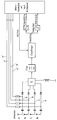
Eine erfindungsgemäß bevorzugte Empfangs- und Auswerteeinrichtung kann beispielsweise einen Aufbau aufweisen, wie in dem einzigen Schaltdiagramm dargestellt. Für ein Fahrzeug, beispielsweise einen Pkw mit vier aktiven Rädern sind vier Empfangsantennen A, B, C, N vorgesehen. Von jeder Antenne A, B, C, N führt je eine Verbindungsleitung a, b, c, n zu einem Summierpunkt S. In jede Verbindungsleitung a, b, c, n ist eine als Schalter wirkende Diode oder ein als Schalter wirkender Transistor eingesetzt. Die Empfänger- und Auswerteeinrichtung ist mit einem Mikrocontroller versehen, der seinerseits mit einer Input-Multiplexerschaltung ausgerüstet ist. Vom Mikrocontroller führt je eine Steuerleitung a', b', c', n' zu der zugeordneten Verbindungsleitung a, b, c, n, um den jeweiligen Schalter anzusteuern und entweder in den Sperrzustand oder in den Durchlaßzustand zu versetzen. Somit kann der Mikrocontroller registrieren, welche Antenne zu einem gegebenen Zeitpunkt auf den Summierpunkt aufgeschaltet ist. Der Summierpunkt ist über ein Filter mit dem Empfänger verbunden. Mit Hilfe des Empfängers wird nicht nur das Funktelegramm demoduliert, sondern es wird auch die Feldstärke erfaßt, die zu einem bestimmten Zeitpunkt am Summierpunkt anliegt. Die anfänglich in analoger Form ermittelte Feldstärke wird mit Hilfe eines Analog/Digital-Wandlers in ein digitales Feldstärkesignal umgewandelt und dem Mikrocontroller zur Auswertung zugeführt. Weiterhin werden nach entsprechender Demodulierung die Nutzsignale über eine Datensignalleitung dem Mikrocontroller zugeführt und ausgewertet.A receiving and evaluating device preferred according to the invention can, for example, have a structure as shown in the single circuit diagram. Four receiving antennas A, B, C, N are provided for a vehicle, for example a car with four active wheels. A connecting line a, b, c, n leads from each antenna A, B, C, N to a summing point S. A diode acting as a switch or a transistor acting as a switch is inserted into each connecting line a, b, c, n. The receiver and evaluation device is provided with a microcontroller, which in turn is equipped with an input multiplexer circuit. A control line a ', b', c ', n' leads from the microcontroller to the associated connecting line a, b, c, n in order to control the respective switch and to put it either in the blocking state or in the forward state. The microcontroller can thus register which antenna is connected to the summing point at a given time. The summing point is connected to the receiver via a filter. With the help of the receiver, not only is the radio telegram demodulated, but the field strength that is present at the summing point at a specific point in time is also recorded. The field strength initially determined in analog form is converted into a digital field strength signal with the aid of an analog / digital converter and fed to the microcontroller for evaluation. Furthermore, after appropriate demodulation, the useful signals are fed to the microcontroller and evaluated via a data signal line.
Claims (27)
sämtlichen Empfangsantennen (A, B, C, ... N) nur ein einziger Empfänger zugeordnet ist, der einerseits mit der Auswerteeinrichtung verbunden ist und der andererseits über je eine Verbindungsleitung (a, b, c, ... n) mit jeder Antenne (A, B, C, ... N) verbunden ist;
diesem Empfänger eine Multiplexerschaltung zugeordnet ist, mit der pro Zeiteinheit nur eine einzige ausgewählte Antenne oder gleichzeitig mehrere ausgewählte Antennen auf den Empfänger geschaltet werden;
dieser Empfänger das Funktelegramm und dessen Feldstärke erfaßt;
durch Auswertung der vom Empfänger erfaßten Feldstärken diejenige Antenne mit der größten Feldstärke selektiert wird; und
anhand dieser selektierten Antenne das Funktelegramm einem bestimmten Rad zugeordnet wird, das sich benachbart zur selektierten Antenne befindet.Tire pressure monitoring device for a vehicle with several wheels, each of which is equipped with a pneumatic tire
only one receiver is assigned to all receiving antennas (A, B, C, ... N), which is connected on the one hand to the evaluation device and on the other hand via a connecting line (a, b, c, ... n) to each antenna (A, B, C, ... N) is connected;
a multiplexer circuit is assigned to this receiver, with which only a single selected antenna or several selected antennas are switched to the receiver per time unit;
this receiver detects the radio telegram and its field strength;
by evaluating the field strengths detected by the receiver, the antenna with the greatest field strength is selected; and
on the basis of this selected antenna, the radio telegram is assigned to a specific wheel which is located adjacent to the selected antenna.
dadurch gekennzeichnet, daß
das Funktelegramm ein HF-Signal ist, das mit einem Digitalsignal moduliert ist, das wenigstens ein Synchronisiersignal und wenigstens ein Nutzsignal aufweist und das wahlweise zusätzlich mit einer Kennung und/oder mit einer Prüfziffer versehen ist; und
die Empfangsantennen (A, B, C, ... N) und der Empfänger für den Empfang solcher HF-Signale ausgelegt sind; und die Auswerteeinrichtung für die Auswertung solche Digitalsignale ausgelegt ist.Tire pressure monitoring device according to claim 1,
characterized in that
the radio telegram is an RF signal which is modulated with a digital signal, which has at least one synchronization signal and at least one useful signal and which is optionally additionally provided with an identifier and / or with a check digit; and
the receiving antennas (A, B, C, ... N) and the receiver are designed to receive such RF signals; and the evaluation device is designed for the evaluation of such digital signals.
dadurch gekennzeichnet, daß
die Auswertung der vom Empfänger erfaßten Feldstärken und die Selektierung der Antenne mit der größten Feldstärke während der Übertragung des Synchronisiersignales eines Funktelegrammes erfolgt.Tire pressure monitoring device according to claim 2,
characterized in that
the field strengths detected by the receiver are evaluated and the antenna with the greatest field strength is selected during the transmission of the synchronization signal of a radio telegram.
dadurch gekennzeichnet, daß
in jede Verbindungsleitung (a, b, c, ... n) je ein Schalter eingesetzt ist; und
die Multiplexerschaltung diese Schalter im Zeitmultiplexverfahren betätigt.Tire pressure monitoring device according to one of claims 1 to 3,
characterized in that
a switch is inserted in each connecting line (a, b, c, ... n); and
the multiplexer circuit operates these switches in time-division multiplexing.
dadurch gekennzeichnet, daß
die Multiplexerschaltung zu einem gegebenen Zeitpunkt während des Empfangs eines Funktelegrammes nur einen einzigen Schalter oder nur zwei Schalter in den Durchlaßzustand versetzt und zu einem späteren Zeitpunkt während des Empfangs des gleichen Funktelegrammes gleichzeitig mehrere Schalter oder alle Schalter in den Durchlaßzustand versetzt.Tire pressure monitoring device according to claim 4,
characterized in that
the multiplexer circuit at a given time during the reception of a radio telegram only puts a single switch or only two switches into the on state and at a later time during the reception of the same radio telegram several switches or all switches simultaneously into the on state.
dadurch gekennzeichnet, daß
die Multiplexerschaltung
characterized in that
the multiplexer circuit
dadurch gekennzeichnet, daß
die Multiplexerschaltung während der Übertragung eines Synchronisiersignales eines Funktelegrammes nacheinander nur jeweils einen einzigen Schalter oder nur zwei Schalter in den Durchlaßzustand versetzt, bis die Antenne mit dem stärksten HF-Signal ermittelt ist; und
die Multiplexerschaltung während der nachfolgenden Übertragung des Nutzsignales dieses Funkttelegrammes mehrere Schalter oder alle Schalter in den Durchlaßzustand versetzt, um so einen Mehrfachempfang dieses Nutzsignales über mehrere Antennen (A, B, C, ... N) zu erreichen.Tire pressure monitoring device according to claim 4 or 5,
characterized in that
the multiplexer circuit during the transmission of a synchronization signal of a radio telegram successively puts only a single switch or only two switches into the on state until the antenna with the strongest RF signal is determined; and
the multiplexer circuit switches several switches or all switches to the on state during the subsequent transmission of the useful signal of this radio telegram in order to achieve multiple reception of this useful signal via several antennas (A, B, C, ... N).
dadurch gekennzeichnet, daß
jeder Schalter als eine Diode ausgebildet ist.Tire pressure monitoring device according to one of claims 4 to 7,
characterized in that
each switch is designed as a diode.
dadurch gekennzeichnet, daß
jeder Schalter als ein Transistor ausgebildet ist.Tire pressure monitoring device according to one of claims 4 to 7,
characterized in that
each switch is designed as a transistor.
dadurch gekennzeichnet, daß
jede Verbindungsleitung (a, b, c, ... n) nach dem Schalter auf einen gemeinsamen Summierpunkt (S) geschaltet ist.Tire pressure monitoring device according to one of claims 4 to 9,
characterized in that
each connecting line (a, b, c, ... n) is connected to a common summing point (S) after the switch.
dadurch gekennzeichnet, daß
am Empfänger die im Summierpunkt gebildeten Feldstärken anliegen; und
die am Empfänger anliegende Feldstärke mit Hilfe eines Analog/Digital-Wandlers in ein digitales Feldstärkesignal umgeformt wird.Tire pressure monitoring device according to claim 10,
characterized in that
the field strengths formed at the summing point are applied to the receiver; and
the field strength applied to the receiver is converted into a digital field strength signal with the aid of an analog / digital converter.
dadurch gekennzeichnet, daß
die Auswerteeinrichtung zusätzlich zu dem Summierpunkt (S), dem Empfänger und der Multiplexerschaltung einen Mikroprozessor aufweist, und
mit Hilfe dieser Komponenten nachstehende Funktionen ausgeführt werden:
characterized in that
the evaluation device in addition to the summing point (S), the receiver and the multiplexer circuit Has microprocessor, and
The following functions can be performed using these components:
dadurch gekennzeichnet, daß
das Synchronisiersignal etwa 8 bis 16 Bits umfaßt.Tire pressure monitoring device according to one of claims 2 to 12.
characterized in that
the synchronization signal comprises approximately 8 to 16 bits.
gekennzeichnet durch:
marked by:
dadurch gekennzeichnet, daß
das Funktelegramm ein HF-Signal ist, das mit einem Digitalsignal moduliert ist, das wenigstens ein Synchronisiersignal und wenigstens ein Nutzsignal aufweist und das wahlweise zusätzlich mit einer Kennung und/oder mit einer Prüfziffer versehen ist; und
die Empfangsantenne (A, B, C, ... N) und der Empfänger für den Empfang solcher HF-Signale ausgelegt sind; und die Auswerteeinrichtung für die Auswertung solcher Digitalsignale ausgelegt ist.Multiple receiver according to claim 14,
characterized in that
the radio telegram is an RF signal which is modulated with a digital signal, which has at least one synchronization signal and at least one useful signal and which is optionally additionally provided with an identifier and / or with a check digit; and
the receiving antenna (A, B, C, ... N) and the receiver are designed to receive such RF signals; and the evaluation device is designed for the evaluation of such digital signals.
dadurch gekennzeichnet, daß
die Auswertung der vom Empfänger erfaßten Feldstärken und die Selektierung der Antenne mit der größten Feldstärke während der Übertragung des Synchronisiersignales eines Funktelegrammes erfolgt.Multiple receiver according to claim 15,
characterized in that
the field strengths detected by the receiver are evaluated and the antenna with the greatest field strength is selected during the transmission of the synchronization signal of a radio telegram.
dadurch gekennzeichnet, daß
in jede Verbindungsleitung (a, b, c, ... n) je ein Schalter eingesetzt ist; und die Multiplexerschaltung diese Schalter im Zeitmultiplexverfahren betätigt.Multiple receiver according to one of Claims 14 to 16,
characterized in that
a switch is inserted in each connecting line (a, b, c, ... n); and the multiplexer circuit actuates these switches in time-division multiplexing.
dadurch gekennzeichnet, daß
die Multiplexerschaltung zu einem gegebenen Zeitpunkt während des Empfangs eines Funktelegramms nur einen einzigen Schalter oder nur zwei Schalter in den Durchlaßzustand versetzt und zu einem späteren Zeitpunkt während des Empfangs des gleichen Funktelegrammes gleichzeitig mehrere Schalter oder alle Schalter in den Durchlaßzustand versetzt.Multiple receiver according to claim 17,
characterized in that
the multiplexer circuit at a given time during the reception of a radio telegram only puts a single switch or only two switches into the on state and at a later time during the reception of the same radio telegram several switches or all switches simultaneously into the on state.
dadurch gekennzeichnet, daß
die Multiplexerschaltung
characterized in that
the multiplexer circuit
dadurch gekennzeichnet, daß
die Multiplexerschaltung während der Übertragung eines Synchronisiersignales eines Funktelegrammes nacheinander nur jeweils einen einzigen Schalter oder nur zwei Schalter in den Durchlaßzustand versetzt, bis die Antenne mit dem stärksten HF-Signal ermittelt ist; und die Multiplexerschaltung während der nachfolgenden Übertragung des Nutzsignales dieses Funkttelegrammes mehrere Schalter oder alle Schalter in den Durchlaßzustand versetzt, um so einen Mehrfachempfang dieses Nutzsignales über mehrere Antennen (A, B, C, ... N) zu erreichen.Multiple receiver according to claim 17,
characterized in that
the multiplexer circuit during the transmission of a synchronization signal of a radio telegram successively puts only a single switch or only two switches into the on state until the antenna with the strongest RF signal is determined; and the multiplexer circuit during the subsequent transmission of the useful signal of this radio telegram puts a plurality of switches or all switches in the pass state, so as to achieve multiple reception of this useful signal via several antennas (A, B, C, ... N).
dadurch gekennzeichnet, daß
jeder Schalter als eine Diode ausgebildet ist.Multiple receiver according to one of Claims 17 to 20,
characterized in that
each switch is designed as a diode.
dadurch gekennzeichnet, daß
jeder Schalter als ein Transistor ausgebildet ist.Multiple receiver according to one of Claims 17 to 20,
characterized in that
each switch is designed as a transistor.
dadurch gekennzeichnet, daß
jede Verbindungsleitung (a, b, c, ... n) nach dem Schalter auf einen gemeinsamen Summierpunkt (S) geschaltet ist.Multiple receiver according to one of Claims 17 to 22,
characterized in that
each connecting line (a, b, c, ... n) is connected to a common summing point (S) after the switch.
dadurch gekennzeichnet, daß
am Empfänger die im Summierpunkt gebildeten Feldstärken anliegen; und
die am Empfänger anliegende Feldstärke mit Hilfe eines Analog/Digital-Wandlers in ein digitales Feldstärkesignal umgeformt wird.Multiple receiver according to claim 23,
characterized in that
the field strengths formed at the summing point are applied to the receiver; and
the field strength applied to the receiver is converted into a digital field strength signal with the aid of an analog / digital converter.
dadurch gekennzeichnet, daß
die Auswerteeinrichtung zusätzlich zu dem Summierpunkt (S), dem Empfänger und der Multiplexerschaltung einen Mikroprozessor aufweist, und
mit Hilfe dieser Komponenten nachstehende Funktionen ausgeführt werden:
characterized in that
the evaluation device has a microprocessor in addition to the summing point (S), the receiver and the multiplexer circuit, and
The following functions can be performed using these components:
dadurch gekennzeichnet, daß
das Synchronisiersignal etwa 8 bis 16 Bits umfaßt.Multiple receiver according to one of Claims 15 to 25,
characterized in that
the synchronization signal comprises approximately 8 to 16 bits.
dadurch gekennzeichnet, daß
die Empfangseinrichtung vier Empfangsantennen (A, B, C, ... N) aufweist; und
jede dieser Empfangsantennen einem aktiven Rad eines Pkw zugeordnet ist.Multiple receiver according to one of Claims 14 to 25,
characterized in that
the receiving device has four receiving antennas (A, B, C, ... N); and
each of these receiving antennas is assigned to an active wheel of a car.
Applications Claiming Priority (2)
| Application Number | Priority Date | Filing Date | Title |
|---|---|---|---|
| DE19534616 | 1995-09-18 | ||
| DE19534616A DE19534616B4 (en) | 1995-09-18 | 1995-09-18 | Tire pressure monitoring device |
Publications (2)
| Publication Number | Publication Date |
|---|---|
| EP0763437A1 true EP0763437A1 (en) | 1997-03-19 |
| EP0763437B1 EP0763437B1 (en) | 2001-07-11 |
Family
ID=7772497
Family Applications (1)
| Application Number | Title | Priority Date | Filing Date |
|---|---|---|---|
| EP96114843A Expired - Lifetime EP0763437B1 (en) | 1995-09-18 | 1996-09-16 | Tyre-pressure surveillance device and multipath receiver therefore |
Country Status (6)
| Country | Link |
|---|---|
| US (1) | US6112585A (en) |
| EP (1) | EP0763437B1 (en) |
| AT (1) | ATE202978T1 (en) |
| CA (1) | CA2185771A1 (en) |
| DE (2) | DE19534616B4 (en) |
| ES (1) | ES2161318T3 (en) |
Cited By (10)
| Publication number | Priority date | Publication date | Assignee | Title |
|---|---|---|---|---|
| WO1998005518A1 (en) * | 1996-08-07 | 1998-02-12 | Doduco Gmbh | Process for evaluating the signals from a tyre pressure monitoring system |
| EP0861160B1 (en) * | 1995-11-17 | 2000-04-05 | Beru AG | Method of allocating transmitters to receiving antennas in tyre-pressure monitoring systems |
| EP0937615A3 (en) * | 1998-02-19 | 2000-08-30 | Siemens Aktiengesellschaft | Sensor system and procedure for monitoring/measuring vehicle tyre adhesion on a surface and other physical data of the tyre |
| FR2798213A1 (en) * | 1999-09-03 | 2001-03-09 | Sagem | VEHICLE TIRE PRESSURE MONITORING SYSTEM |
| EP1077144A3 (en) * | 1999-08-17 | 2003-08-27 | Pacific Industrial Co., Ltd. | Tire inflation pressure monitor and monitoring method |
| EP1440824A2 (en) * | 2003-01-22 | 2004-07-28 | Nissan Motor Company, Limited | Tire pressure monitoring apparatus and process |
| FR2866269A1 (en) | 2004-01-07 | 2005-08-19 | Siemens Ag | DEVICE AND METHOD FOR DETERMINING THE LATERAL POSITION OF WHEELS |
| DE10221593B4 (en) * | 2001-05-17 | 2005-12-22 | Lite-On Automotive Corp. | Code detection device |
| EP1859562A2 (en) * | 2005-03-10 | 2007-11-28 | Dephi Technologies, INC. | Tire pressure monitor with diversity antenna system and method |
| CN104401191A (en) * | 2014-11-28 | 2015-03-11 | 埃泰克汽车电子(芜湖)有限公司 | Detection device and detection method for calibration of TPMS (tire pressure monitoring system) |
Families Citing this family (52)
| Publication number | Priority date | Publication date | Assignee | Title |
|---|---|---|---|---|
| US6662642B2 (en) | 2000-09-08 | 2003-12-16 | Automotive Technologies International, Inc. | Vehicle wireless sensing and communication system |
| US6748797B2 (en) | 2000-09-08 | 2004-06-15 | Automotive Technologies International Inc. | Method and apparatus for monitoring tires |
| US7421321B2 (en) * | 1995-06-07 | 2008-09-02 | Automotive Technologies International, Inc. | System for obtaining vehicular information |
| US9443358B2 (en) | 1995-06-07 | 2016-09-13 | Automotive Vehicular Sciences LLC | Vehicle software upgrade techniques |
| DE19737945B4 (en) * | 1997-08-30 | 2004-05-19 | Continental Aktiengesellschaft | Method for the transmission of data in a data transmission system and data transmission system |
| DE19852454B4 (en) * | 1997-12-08 | 2005-11-10 | Fraunhofer-Gesellschaft zur Förderung der angewandten Forschung e.V. | Apparatus and method for improving radio transmission over a radio link between a transmitter and a receiver |
| US10240935B2 (en) | 1998-10-22 | 2019-03-26 | American Vehicular Sciences Llc | Vehicle software upgrade techniques |
| US6710708B2 (en) * | 1999-02-05 | 2004-03-23 | Schrader-Bridgeport International, Inc. | Method and apparatus for a remote tire pressure monitoring system |
| DE19917210A1 (en) * | 1999-04-16 | 2000-10-26 | Hydac Technology Gmbh | Monitoring pre-filling gas pressure in hydraulic reservoirs involves interrupting pressure feed to oil side, emptying reservoir; measuring gas temp. until temp. balance achieved |
| US6919799B2 (en) * | 1999-04-29 | 2005-07-19 | Bridgestone/Firestone North American Tire, Llc | Monitoring device and tire combination |
| DE19938431C2 (en) * | 1999-08-13 | 2001-09-27 | Continental Ag | System for a motor vehicle with a radio frequency transmitter and a radio frequency receiver |
| US7467034B2 (en) * | 2002-11-04 | 2008-12-16 | Automotive Technologies International, Inc. | Tire monitoring techniques |
| US8266465B2 (en) | 2000-07-26 | 2012-09-11 | Bridgestone Americas Tire Operation, LLC | System for conserving battery life in a battery operated device |
| US7161476B2 (en) | 2000-07-26 | 2007-01-09 | Bridgestone Firestone North American Tire, Llc | Electronic tire management system |
| EP1309460B1 (en) | 2000-07-26 | 2010-08-25 | Bridgestone Americas Tire Operations, LLC | Electronic tire management system |
| DE10044365A1 (en) * | 2000-09-08 | 2002-04-04 | Hans Zapfe | Method and arrangement for monitoring take-offs and landings of aircraft |
| US7911324B2 (en) * | 2001-02-16 | 2011-03-22 | Automotive Technologies International, Inc. | Method and system for obtaining information about RFID-equipped objects |
| US6362731B1 (en) * | 2000-12-06 | 2002-03-26 | Eaton Corporation | Tire pressure monitor and location identification system and method |
| JP2002240521A (en) | 2000-12-15 | 2002-08-28 | Pacific Ind Co Ltd | Tire condition monitoring device |
| JP3818632B2 (en) | 2000-12-27 | 2006-09-06 | 太平洋工業株式会社 | Tire condition monitoring apparatus and tire condition monitoring method |
| US6501372B2 (en) * | 2001-02-02 | 2002-12-31 | Trw Inc. | Tire condition sensor communication with unique sampling on vehicle-side diversity antenna array |
| US9084076B2 (en) | 2001-02-16 | 2015-07-14 | Intelligent Technologies International, Inc. | Techniques for obtaining information about objects |
| US6340930B1 (en) | 2001-03-07 | 2002-01-22 | Trw Inc. | System and method for monitoring a condition of a vehicle tire |
| FR2826731B1 (en) * | 2001-06-28 | 2005-02-25 | Siemens Automotive Sa | METHOD FOR LOCATING SENSORS MOUNTED EACH ON A VEHICLE WHEEL |
| US7423532B2 (en) * | 2001-10-29 | 2008-09-09 | Schrader Bridgeport International, Inc. | Determination of wheel sensor position using a single radio frequency detector in an automotive remote tire monitor system |
| US6882270B2 (en) | 2001-10-29 | 2005-04-19 | Schrader Bridgeport International, Inc. | Determination of wheel sensor position using radio frequency detectors in an automotive remote tire monitor system |
| JP2003182328A (en) * | 2001-12-21 | 2003-07-03 | Pacific Ind Co Ltd | Tire state monitor and transmitter therefor |
| JP4000891B2 (en) * | 2002-04-12 | 2007-10-31 | トヨタ自動車株式会社 | Tire condition acquisition device |
| US7010968B2 (en) * | 2002-04-18 | 2006-03-14 | Schrader Bridgeport International, Inc. | Determination of wheel sensor position using a wireless solution |
| JP4041958B2 (en) * | 2002-07-18 | 2008-02-06 | オムロン株式会社 | Antenna device and tire pressure monitoring system including the antenna device |
| JP3636184B2 (en) * | 2002-07-31 | 2005-04-06 | 株式会社デンソー | Tire pressure sensor ID registration method and ID registration system, tire pressure monitoring system, tire pressure sensor, and smart control system |
| DE10240159B3 (en) * | 2002-08-30 | 2004-07-15 | Nolex Ag | Automobile tire pressure control device, has each wheel provided with surface wave device acting as identification marking for identification of transmitted tire pressure data |
| JP2004196007A (en) * | 2002-12-16 | 2004-07-15 | Calsonic Kansei Corp | Tire pressure detecting device |
| DE10316074B4 (en) * | 2003-04-08 | 2006-01-26 | Global Dynamix Ag | Tire air pressure monitoring device |
| DE10341785B4 (en) * | 2003-09-10 | 2006-04-27 | Global Dynamix Ag | Method for assigning a wheel module to its wheel position and suitable tire air pressure control device |
| JP2005119370A (en) * | 2003-10-14 | 2005-05-12 | Pacific Ind Co Ltd | Transmitter of tire condition monitoring device |
| DE10355897A1 (en) * | 2003-11-29 | 2005-06-30 | Daimlerchrysler Ag | Method for activating an operating mode of a vehicle system |
| EP1547879A3 (en) * | 2003-12-25 | 2006-03-01 | Omron Corporation | Vehicular remote control system and tire pressure monitoring system |
| US7367227B2 (en) * | 2004-01-20 | 2008-05-06 | Schrader Bridgeport International | Determination of wheel sensor position using shock sensors and a wireless solution |
| US7362218B2 (en) * | 2004-01-20 | 2008-04-22 | Schrader Bridgeport International, Inc. | Motion detection using a shock sensor in a remote tire pressure monitoring system |
| DE102004018827B4 (en) * | 2004-04-19 | 2006-06-29 | Siemens Ag | Device and method for determining the wheel position of wheels of a wheeled vehicle |
| DE102004024388B4 (en) * | 2004-05-17 | 2006-07-06 | Siemens Ag | Vehicle wheel`s position determining device, has evaluation device for determining position of wheel based on disturbing components of acceleration signal that is caused by unevenness of road surface |
| CA2570525C (en) | 2004-06-16 | 2009-07-21 | Bridgestone Corporation | Tire management system |
| DE102004032698A1 (en) * | 2004-07-06 | 2006-02-16 | Siemens Ag | Apparatus and method for determining a wheel position |
| DE102004034287A1 (en) * | 2004-07-15 | 2006-02-23 | Siemens Ag | Procedure for localization of vehicle wheel involves evaluation by evaluation unit which receives signals from acceleration sensor placed at wheel to localize wheel |
| DE102004040790A1 (en) * | 2004-08-23 | 2006-03-16 | Global Dynamix Ag | Device for controlling tire air pressure for commercial vehicles comprises a control unit having a foot part connected to the vehicle and a mobile part having an input unit for directly inputting different wheel positions |
| DE102004042191B3 (en) * | 2004-08-31 | 2006-02-23 | Siemens Ag | Vehicle wheel location procedure measures tangential acceleration signature |
| JP5019839B2 (en) * | 2006-10-04 | 2012-09-05 | 株式会社ブリヂストン | Tire information management system |
| TWI327534B (en) * | 2007-04-11 | 2010-07-21 | Kuender & Co Ltd | Tire identification system, tire pressure monitoring system using the same and method for tire identification |
| KR101365925B1 (en) * | 2010-05-13 | 2014-02-25 | 주식회사 만도 | Identification Device For Tire Pressure Sensing Module |
| JP2013023868A (en) * | 2011-07-19 | 2013-02-04 | Tokai Rika Co Ltd | Function integrated receiver |
| US10216523B2 (en) | 2015-07-17 | 2019-02-26 | General Electric Company | Systems and methods for implementing control logic |
Citations (3)
| Publication number | Priority date | Publication date | Assignee | Title |
|---|---|---|---|---|
| FR2441502A1 (en) * | 1978-11-20 | 1980-06-13 | Pappas Dennis | Insufficient tyre pressure alarm device - has pressure sensor at each wheel transmitting to receiver in driver's cabin |
| DE3104013A1 (en) * | 1980-02-07 | 1982-02-25 | Meisei Electric Co., Ltd., Tokyo | System for detecting an abnormal internal tyre pressure |
| DE4205911A1 (en) * | 1992-02-26 | 1993-09-02 | Uwatec Ag | CONTROL DEVICE FOR THE AIR PRESSURE OF AIR TIRED VEHICLE WHEELS |
Family Cites Families (15)
| Publication number | Priority date | Publication date | Assignee | Title |
|---|---|---|---|---|
| US4578992A (en) * | 1982-11-05 | 1986-04-01 | Philip E. Galasko | Detection of a low pressure condition of a vehicle tire |
| FR2577480B1 (en) * | 1985-02-21 | 1987-12-11 | Labinal | DEVICE FOR MEASURING BRAKE TEMPERATURES AND TIRE PRESSURES ON VEHICLE WHEEL TRAINS AND ESPECIALLY AIRCRAFT |
| US4978941A (en) * | 1988-07-11 | 1990-12-18 | Air Chex, Inc. | Low tire pressure detector |
| DE3930480A1 (en) * | 1989-09-12 | 1991-03-14 | Rainer Achterholt | A VALVE CAP FOR A TIRE GENERATING A PRESSURE RELEASE SIGNAL |
| DE3930479A1 (en) * | 1989-09-12 | 1991-03-14 | Rainer Achterholt | VALVE WITH SIGNAL GENERATING DEVICE FOR VEHICLE TIRE |
| US5297424A (en) * | 1990-03-07 | 1994-03-29 | Monroe Auto Equipment Company | Telemetry system for tire pressure and temperature sensing |
| US5289160A (en) * | 1991-09-30 | 1994-02-22 | Fiorletta Carl A | Tire pressure monitoring system |
| DE4303591C2 (en) * | 1993-02-08 | 1996-02-22 | Alpha Beta Electronics Ag | Valve cap with a device for generating a pressure indication signal for a vehicle tire equipped with a valve |
| DE4303583C2 (en) * | 1993-02-08 | 1996-02-22 | Alpha Beta Electronics Ag | Valve with a device for generating a wirelessly transmitted pressure decrease signal for vehicle tires |
| US5731754A (en) * | 1994-06-03 | 1998-03-24 | Computer Methods Corporation | Transponder and sensor apparatus for sensing and transmitting vehicle tire parameter data |
| US5585554A (en) * | 1994-10-31 | 1996-12-17 | Handfield; Michael | System and method for monitoring a pneumatic tire |
| DE19518806A1 (en) * | 1995-05-26 | 1996-11-28 | Duerrwaechter E Dr Doduco | Device on vehicles for monitoring the air pressure in its tires |
| DE19618658A1 (en) * | 1996-05-09 | 1997-11-13 | Continental Ag | Air pressure control system |
| DE19632150B4 (en) * | 1996-08-09 | 2004-06-09 | Conti Temic Microelectronic Gmbh | Method for checking the air pressure in the tires of motor vehicle wheels |
| EP0832765B1 (en) * | 1996-09-27 | 2003-05-28 | Motorola, Inc. | Tyre pressure monitoring system |
-
1995
- 1995-09-18 DE DE19534616A patent/DE19534616B4/en not_active Expired - Fee Related
-
1996
- 1996-09-05 US US08/708,579 patent/US6112585A/en not_active Expired - Fee Related
- 1996-09-16 EP EP96114843A patent/EP0763437B1/en not_active Expired - Lifetime
- 1996-09-16 DE DE59607259T patent/DE59607259D1/en not_active Expired - Fee Related
- 1996-09-16 ES ES96114843T patent/ES2161318T3/en not_active Expired - Lifetime
- 1996-09-16 AT AT96114843T patent/ATE202978T1/en not_active IP Right Cessation
- 1996-09-17 CA CA002185771A patent/CA2185771A1/en not_active Abandoned
Patent Citations (4)
| Publication number | Priority date | Publication date | Assignee | Title |
|---|---|---|---|---|
| FR2441502A1 (en) * | 1978-11-20 | 1980-06-13 | Pappas Dennis | Insufficient tyre pressure alarm device - has pressure sensor at each wheel transmitting to receiver in driver's cabin |
| DE3104013A1 (en) * | 1980-02-07 | 1982-02-25 | Meisei Electric Co., Ltd., Tokyo | System for detecting an abnormal internal tyre pressure |
| DE4205911A1 (en) * | 1992-02-26 | 1993-09-02 | Uwatec Ag | CONTROL DEVICE FOR THE AIR PRESSURE OF AIR TIRED VEHICLE WHEELS |
| WO1993016891A1 (en) * | 1992-02-26 | 1993-09-02 | Uwatec Ag | Device for monitoring the air-pressure in pneumatic tyres fitted on vehicle wheels |
Cited By (14)
| Publication number | Priority date | Publication date | Assignee | Title |
|---|---|---|---|---|
| EP0861160B1 (en) * | 1995-11-17 | 2000-04-05 | Beru AG | Method of allocating transmitters to receiving antennas in tyre-pressure monitoring systems |
| WO1998005518A1 (en) * | 1996-08-07 | 1998-02-12 | Doduco Gmbh | Process for evaluating the signals from a tyre pressure monitoring system |
| US6034597A (en) * | 1996-08-07 | 2000-03-07 | Ami Doduco Gmbh | Process for evaluating the signals from a tire pressure monitoring system |
| EP0937615A3 (en) * | 1998-02-19 | 2000-08-30 | Siemens Aktiengesellschaft | Sensor system and procedure for monitoring/measuring vehicle tyre adhesion on a surface and other physical data of the tyre |
| EP1077144A3 (en) * | 1999-08-17 | 2003-08-27 | Pacific Industrial Co., Ltd. | Tire inflation pressure monitor and monitoring method |
| WO2001017805A1 (en) * | 1999-09-03 | 2001-03-15 | Sagem Sa | System for controlling the pressure of a vehicle tyres |
| FR2798213A1 (en) * | 1999-09-03 | 2001-03-09 | Sagem | VEHICLE TIRE PRESSURE MONITORING SYSTEM |
| DE10221593B4 (en) * | 2001-05-17 | 2005-12-22 | Lite-On Automotive Corp. | Code detection device |
| EP1440824A2 (en) * | 2003-01-22 | 2004-07-28 | Nissan Motor Company, Limited | Tire pressure monitoring apparatus and process |
| EP1440824A3 (en) * | 2003-01-22 | 2008-09-10 | Nissan Motor Company, Limited | Tire pressure monitoring apparatus and process |
| FR2866269A1 (en) | 2004-01-07 | 2005-08-19 | Siemens Ag | DEVICE AND METHOD FOR DETERMINING THE LATERAL POSITION OF WHEELS |
| EP1859562A2 (en) * | 2005-03-10 | 2007-11-28 | Dephi Technologies, INC. | Tire pressure monitor with diversity antenna system and method |
| EP1859562A4 (en) * | 2005-03-10 | 2011-06-15 | Delphi Tech Inc | Tire pressure monitor with diversity antenna system and method |
| CN104401191A (en) * | 2014-11-28 | 2015-03-11 | 埃泰克汽车电子(芜湖)有限公司 | Detection device and detection method for calibration of TPMS (tire pressure monitoring system) |
Also Published As
| Publication number | Publication date |
|---|---|
| DE19534616A1 (en) | 1997-03-20 |
| US6112585A (en) | 2000-09-05 |
| ATE202978T1 (en) | 2001-07-15 |
| CA2185771A1 (en) | 1997-03-19 |
| ES2161318T3 (en) | 2001-12-01 |
| EP0763437B1 (en) | 2001-07-11 |
| DE59607259D1 (en) | 2001-08-16 |
| DE19534616B4 (en) | 2007-01-11 |
Similar Documents
| Publication | Publication Date | Title |
|---|---|---|
| EP0763437A1 (en) | Tyre-pressure surveillance device | |
| EP0915764B1 (en) | Process for evaluating the signals from a tyre pressure monitoring system | |
| DE10014076B4 (en) | Tire pressure display device | |
| DE19720123C2 (en) | Method and device for transmitting telecontrol commands and measurement data to one or more actuators or monitoring devices in an automobile | |
| EP1052119B1 (en) | Method for determining the position of each wheel for a tyre pressure monitoring system of a motor car | |
| EP0828621B1 (en) | Device fitted on vehicles for monitoring tyre pressure | |
| EP1135268B1 (en) | Arrangement for transmitting signals from a device monitoring tyre pressure on the wheels of a motor vehicle to an evaluation device arranged in a motor vehicle | |
| DE102004032698A1 (en) | Apparatus and method for determining a wheel position | |
| DE102005059715B4 (en) | Method and device for locating the position of wheels of a motor vehicle | |
| EP1807270B1 (en) | Tyre pressure control system for a motor vehicle | |
| DE3820454A1 (en) | AREA MESSAGE TRANSMISSION SYSTEM | |
| DE10014949A1 (en) | Device on vehicles with wheels that have pneumatic tires for use in a tire pressure monitoring system | |
| DE10241432A1 (en) | Tire condition monitor and method | |
| DE3417956C2 (en) | ||
| DE10224284A1 (en) | Use authorization verification method | |
| EP0567905B1 (en) | A bidirectional data transmission system between a beacon and a vehicle | |
| EP1550239B1 (en) | Method for transmitting a data protocol on a hf radio link | |
| DE102007044395B4 (en) | Method and device for assigning a first vehicle to a second vehicle | |
| EP0944485B1 (en) | Method for detecting where a given wheel is located on a vehilce that is equipped with a wheel pressure checking device | |
| DE19734749C2 (en) | Device for supplying electrical equipment in motor vehicles | |
| DE10152337A1 (en) | Method and system for determining wheel positions | |
| EP0609694B1 (en) | Transmitter-receiver and method for transmitting and receiving digital information | |
| DE10229465B4 (en) | Arrangement for monitoring at least one parameter for a plurality of vehicle wheels | |
| DE10221593B4 (en) | Code detection device | |
| EP0767554A2 (en) | Receiver with Radio Data System with a supplementary receiver |
Legal Events
| Date | Code | Title | Description |
|---|---|---|---|
| PUAI | Public reference made under article 153(3) epc to a published international application that has entered the european phase |
Free format text: ORIGINAL CODE: 0009012 |
|
| AK | Designated contracting states |
Kind code of ref document: A1 Designated state(s): AT BE CH DE ES FR GB IT LI SE |
|
| 17P | Request for examination filed |
Effective date: 19970428 |
|
| 17Q | First examination report despatched |
Effective date: 20000125 |
|
| RTI1 | Title (correction) |
Free format text: TYRE-PRESSURE SURVEILLANCE DEVICE AND MULTIPATH RECEIVER THEREFORE |
|
| GRAG | Despatch of communication of intention to grant |
Free format text: ORIGINAL CODE: EPIDOS AGRA |
|
| GRAG | Despatch of communication of intention to grant |
Free format text: ORIGINAL CODE: EPIDOS AGRA |
|
| GRAH | Despatch of communication of intention to grant a patent |
Free format text: ORIGINAL CODE: EPIDOS IGRA |
|
| GRAH | Despatch of communication of intention to grant a patent |
Free format text: ORIGINAL CODE: EPIDOS IGRA |
|
| GRAA | (expected) grant |
Free format text: ORIGINAL CODE: 0009210 |
|
| AK | Designated contracting states |
Kind code of ref document: B1 Designated state(s): AT BE CH DE ES FR GB IT LI SE |
|
| REF | Corresponds to: |
Ref document number: 202978 Country of ref document: AT Date of ref document: 20010715 Kind code of ref document: T |
|
| REG | Reference to a national code |
Ref country code: CH Ref legal event code: EP |
|
| REF | Corresponds to: |
Ref document number: 59607259 Country of ref document: DE Date of ref document: 20010816 |
|
| ITF | It: translation for a ep patent filed |
Owner name: A. BRE. MAR. S.R.L. |
|
| GBT | Gb: translation of ep patent filed (gb section 77(6)(a)/1977) |
Effective date: 20010925 |
|
| REG | Reference to a national code |
Ref country code: CH Ref legal event code: NV Representative=s name: LUCHS & PARTNER PATENTANWAELTE |
|
| REG | Reference to a national code |
Ref country code: ES Ref legal event code: FG2A Ref document number: 2161318 Country of ref document: ES Kind code of ref document: T3 |
|
| ET | Fr: translation filed | ||
| REG | Reference to a national code |
Ref country code: GB Ref legal event code: IF02 |
|
| PLBE | No opposition filed within time limit |
Free format text: ORIGINAL CODE: 0009261 |
|
| STAA | Information on the status of an ep patent application or granted ep patent |
Free format text: STATUS: NO OPPOSITION FILED WITHIN TIME LIMIT |
|
| 26N | No opposition filed | ||
| PGFP | Annual fee paid to national office [announced via postgrant information from national office to epo] |
Ref country code: DE Payment date: 20050822 Year of fee payment: 10 |
|
| PGFP | Annual fee paid to national office [announced via postgrant information from national office to epo] |
Ref country code: GB Payment date: 20050902 Year of fee payment: 10 |
|
| PGFP | Annual fee paid to national office [announced via postgrant information from national office to epo] |
Ref country code: FR Payment date: 20050920 Year of fee payment: 10 |
|
| PGFP | Annual fee paid to national office [announced via postgrant information from national office to epo] |
Ref country code: BE Payment date: 20050922 Year of fee payment: 10 Ref country code: AT Payment date: 20050922 Year of fee payment: 10 |
|
| PGFP | Annual fee paid to national office [announced via postgrant information from national office to epo] |
Ref country code: SE Payment date: 20050923 Year of fee payment: 10 Ref country code: CH Payment date: 20050923 Year of fee payment: 10 |
|
| PGFP | Annual fee paid to national office [announced via postgrant information from national office to epo] |
Ref country code: ES Payment date: 20050927 Year of fee payment: 10 |
|
| PG25 | Lapsed in a contracting state [announced via postgrant information from national office to epo] |
Ref country code: AT Free format text: LAPSE BECAUSE OF NON-PAYMENT OF DUE FEES Effective date: 20060916 |
|
| PG25 | Lapsed in a contracting state [announced via postgrant information from national office to epo] |
Ref country code: SE Free format text: LAPSE BECAUSE OF NON-PAYMENT OF DUE FEES Effective date: 20060917 |
|
| PG25 | Lapsed in a contracting state [announced via postgrant information from national office to epo] |
Ref country code: LI Free format text: LAPSE BECAUSE OF NON-PAYMENT OF DUE FEES Effective date: 20060930 Ref country code: CH Free format text: LAPSE BECAUSE OF NON-PAYMENT OF DUE FEES Effective date: 20060930 Ref country code: BE Free format text: LAPSE BECAUSE OF NON-PAYMENT OF DUE FEES Effective date: 20060930 |
|
| PGFP | Annual fee paid to national office [announced via postgrant information from national office to epo] |
Ref country code: IT Payment date: 20060930 Year of fee payment: 11 |
|
| PG25 | Lapsed in a contracting state [announced via postgrant information from national office to epo] |
Ref country code: DE Free format text: LAPSE BECAUSE OF NON-PAYMENT OF DUE FEES Effective date: 20070403 |
|
| REG | Reference to a national code |
Ref country code: CH Ref legal event code: PL |
|
| EUG | Se: european patent has lapsed | ||
| GBPC | Gb: european patent ceased through non-payment of renewal fee |
Effective date: 20060916 |
|
| REG | Reference to a national code |
Ref country code: FR Ref legal event code: ST Effective date: 20070531 |
|
| PG25 | Lapsed in a contracting state [announced via postgrant information from national office to epo] |
Ref country code: GB Free format text: LAPSE BECAUSE OF NON-PAYMENT OF DUE FEES Effective date: 20060916 |
|
| REG | Reference to a national code |
Ref country code: ES Ref legal event code: FD2A Effective date: 20060918 |
|
| BERE | Be: lapsed |
Owner name: *ALPHA-BETA ELECTRONICS A.G. Effective date: 20060930 |
|
| PG25 | Lapsed in a contracting state [announced via postgrant information from national office to epo] |
Ref country code: ES Free format text: LAPSE BECAUSE OF NON-PAYMENT OF DUE FEES Effective date: 20060918 |
|
| PG25 | Lapsed in a contracting state [announced via postgrant information from national office to epo] |
Ref country code: FR Free format text: LAPSE BECAUSE OF NON-PAYMENT OF DUE FEES Effective date: 20061002 |
|
| PG25 | Lapsed in a contracting state [announced via postgrant information from national office to epo] |
Ref country code: IT Free format text: LAPSE BECAUSE OF NON-PAYMENT OF DUE FEES Effective date: 20070916 |