EP0761863A1 - Drier with a gas heating device - Google Patents
Drier with a gas heating device Download PDFInfo
- Publication number
- EP0761863A1 EP0761863A1 EP96710012A EP96710012A EP0761863A1 EP 0761863 A1 EP0761863 A1 EP 0761863A1 EP 96710012 A EP96710012 A EP 96710012A EP 96710012 A EP96710012 A EP 96710012A EP 0761863 A1 EP0761863 A1 EP 0761863A1
- Authority
- EP
- European Patent Office
- Prior art keywords
- burner
- air supply
- gas
- primary air
- clothes dryer
- Prior art date
- Legal status (The legal status is an assumption and is not a legal conclusion. Google has not performed a legal analysis and makes no representation as to the accuracy of the status listed.)
- Granted
Links
Images


Classifications
-
- D—TEXTILES; PAPER
- D06—TREATMENT OF TEXTILES OR THE LIKE; LAUNDERING; FLEXIBLE MATERIALS NOT OTHERWISE PROVIDED FOR
- D06F—LAUNDERING, DRYING, IRONING, PRESSING OR FOLDING TEXTILE ARTICLES
- D06F58/00—Domestic laundry dryers
- D06F58/20—General details of domestic laundry dryers
- D06F58/26—Heating arrangements, e.g. gas heating equipment
- D06F58/263—Gas heating equipment
Definitions
- Clothes dryer with a drum for receiving laundry to be dried, with a blower for generating a process air flow passed through the drum, with a gas-heated heating device for heating the process air flow through a burner, the gas being mixed with primary air as combustion air in front of the burner surface.
- the secondary air flows around the flame to prevent the flame from coming into contact with the walls of the combustion chamber and thus preventing heat from being transferred to the housing. If the predominant part of the combustion air is supplied secondarily in the area of the burner surface, the mixture with the fuel gas is no longer optimal and there is a relatively pollutant-rich combustion. In addition, the combustion path or flame is relatively long and the amount of soot is high.
- EP 0 616 070 A1 also discloses a gas-heated clothes dryer with an automatic burner control unit which has an integrated ignition and flame monitor.
- the safety function of this automatic burner control unit is limited to simple monitoring of the ignition process and the flame using a flame sensor and a control unit, which gives a signal when the flame is absent and cuts off the gas supply within a defined period of time.
- the invention is therefore based on the object of providing a gas-heated clothes dryer with the lowest possible gas consumption and low pollutant content of the combustion exhaust gases while complying with the applicable safety regulations. Another object of the invention is to adapt a commercial household exhaust air dryer to gas-fired operation. In addition, a low-pollutant burner for gas-fired heating systems is to be created.
- the advantages that can be achieved with the invention are, in particular, that the required combustion air is supplied exclusively as primary air via the mixing chamber upstream of the burner, so that an optimal mixture of air and fuel gas is already present before the combustion begins.
- a particular advantage lies in the fact that a constant proportion of primary air and a proportion of the primary air that can be changed as a function of the burner temperature can be supplied via the primary air supply openings of the mixing chamber. This results in optimal burner conditions with regard to the pollutant content of the exhaust gases and the flame quality.
- the secondary air is supplied for cooling the combustion chamber and does not come into contact with the burner or the flame. With the burner according to the invention, low-pollutant combustion takes place with a short combustion path or a short flame.
- the flame has a blue flame pattern and is extremely low in soot. Since no secondary air is supplied to the burner surface on the burner surface, the flame is not levered off the burner surface.
- the secondary air supplied via the annular gap between the combustion chamber and the process air channel or a cladding tube enveloping the combustion chamber is heated on the outer surface of the combustion chamber and passed through the drum as process air together with a tertiary air component which can be fed in behind the burner.
- the exhaust gases entrained in the process air flow are diluted to such an extent that they can be passed through the drum without any problems and can be discharged to the outside via the exhaust air line of the dryer.
- the blower for the process air flow is arranged in the process air duct behind the drum.
- the burner is in the negative pressure range, which is the
- the advantage is that exhaust gas components do not escape from the process air duct in front of the drum or from the drum.
- a further advantage lies in the special design of an exhaust air dryer according to claim 10 and the claim based thereon, in which a gas-heated heating device is provided instead of an electrically heated heating device.
- An automatic burner control with integrated safety functions is connected to the signal output for the heating.
- all components of a conventional exhaust air dryer can be adopted.
- a particular advantage of this design is that a uniform program control device can be used, since all gas-specific additional functions are controlled by the automatic burner control unit.
- the burner according to the invention according to claim 12 can generally be used in gas-heated heating devices.
- FIG. 1 the structure of a dryer with a gas-heated heating device and the air flow of process air and combustion air is shown schematically.
- the tumble dryer has a rotatably mounted drum (1) for receiving the laundry to be dried, which is closed by a door (2).
- the burner (5) of the gas-heated heating device is arranged in the process air duct (3) at the drum inlet (4).
- the process air is sucked in via the process air blower (6) in the process air duct (7) at the drum outlet (8) and passed through the drum (1) and then released to the environment via the exhaust air opening (9).
- a drying program can be selected via the operating and display device (10) and information on safety functions can be displayed.
- the burner (5) is shown as a detail.
- the burner (5) has an upstream mixing chamber (11) into which a gas nozzle (12) projects, which has air inlet openings (13) (13 ') for the primary air P.
- the primary air is sucked in by the injector action of the gas nozzle (12) and the process air blower, mixed with the gas in the mixing chamber (11) and then fed to the combustion chamber (14).
- the burner tube (15) is arranged concentrically in the cylindrical combustion chamber (14).
- the burner tube (15) is designed as a welded tube and has flame slots (17) arranged on its lateral surface transversely to the weld seam (16).
- the burner tube (15) has a mixing cone (18) or, as shown in FIG.
- a mixing tube (18 ') as a distributor for the gas / air mixture.
- the mixing tube (18 ') is perforated and open towards the end of the burner tube. This results in a cooling effect on the closed burner plate (15 ') at the end of the burner tube.
- a glow igniter (19) or an HF igniter (20) is assigned to the burner tube (15).
- the cylindrical combustion chamber (14) is surrounded by a cladding tube (21) or the process air duct.
- Secondary air S is drawn in as cooling air for the combustion chamber (14) in the area of the burner inlet via the annular gap (22) between the outer surface (14 ') of the combustion chamber (14) and the cladding tube (21) or process air duct.
- the secondary air S heats up on the outer surface (14 ') of the combustion chamber (14) and, together with the primary air component of the combustion air and a tertiary air component T supplied behind the combustion chamber (14), forms the process air flow which is passed through the drum (1).
- the proportion of exhaust gas in the process air is so low that no separate exhaust gas routing is required and the dryer exhaust air line can be used.
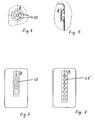
- Figure 3 shows that the mixing chamber (11) is formed with at least one primary air supply opening (13) of constant opening cross-section, through which at least 1/16 of the process air volume can be supplied.
- the mixing chamber (11) also has an additional controllable primary air supply opening (13 ').
- the opening cross section of this additional primary air opening (13 ') can be changed depending on the burner temperature.
- a bi-metal "B" which partially or completely closes the additional primary air supply opening (13 ') and is exposed to the influence of the burner temperature is arranged on the mixing chamber (11).
- the bimetal is blackened and exposed to the heat radiation of the burner plate (15 ') at the end of the burner tube.
- the bimetal is circular and embossed, as a result of which the additional primary air supply opening (13 ') opens suddenly, as indicated in FIG. 5, when the temperature rises accordingly.
- Figures 6 and 7 show a flat bi-metal according to Figure 3 that covers one or more primary air supply openings (13 '). In this version, the primary air supply changes slowly.
- FIG. 8 shows a diagram of an exhaust air dryer.
- the tumble dryer has an operating and display device (10) via which the operator selects appropriate drying programs.
- the sequence of the drying programs is controlled by a control part (23) for the time or state-dependent execution of the drying program, the signal inputs and outputs of which are connected to a power unit (24) via which the operating components such as the motor (25), blower ( 26) and heating the dryer.
- This structure of a tumble dryer is known for electrically heated tumble dryers.
- the laundry dryer according to the invention has a gas-heated heating device (27) instead of an electrically heated heating device.
- an automatic gas burner (29) at the signal input and output (28) of the power section for the heater, through which all gas heating-specific additional functions are controlled. Additional functions specific to gas heating are e.g. B. the ignition and flame monitoring and the control of the gas valve with the required safety times.
- the mode of operation of the automatic burner control unit (29) when using an HF igniter (20) is described below.
- the function of the flame monitor is checked. If there is no fault message, the gas valve opens and the spark generator starts. If the ionization electrode of the flame monitor (30) senses a flame or if the ignition time (approx. 5s) has elapsed, the ignition spark generator stops. In the event of a flame failure, the gas valve closes within one second and a restart is initiated. If no flame is reported after a safety time ( ⁇ 10s), the automatic burner control unit (29) goes into trouble, which is indicated by a display (31) in the operating and display device (10). After a locking time of min.
- the automatic burner control unit (29) can be restarted by a reset signal. If the spark generator malfunctions, gas can flow into the dryer. Since the reset signal is operated by the program control device and approximately 3 to 5 fault messages for a tumble dryer, whether gas or electrically heated, should be permissible, more and more gas collects in the dryer.
- the gas burner control unit (29) in combination with the dryer control initiates a rinsing phase after each fault message, in which the process air path (drum and exhaust air line) is subjected to an air exchange. For this purpose, only the process air blower (6) is put into operation for a few seconds.
Landscapes
- Engineering & Computer Science (AREA)
- Textile Engineering (AREA)
- Detail Structures Of Washing Machines And Dryers (AREA)
- Drying Of Solid Materials (AREA)
Abstract
Description
Wäschetrockner mit einer Trommel zur Aufnahme von zu trocknender Wäsche, mit einem Gebläse zur Erzeugung eines durch die Trommel geleiteten Prozeßluftstromes, mit einer gasbeheizten Heizungseinrichtung zur Erwärmung des Prozeßluftstromes durch einen Brenner, wobei dem Gas Primärluft als Verbrennungsluft vor der Brenneroberfläche zugemischt wird.Clothes dryer with a drum for receiving laundry to be dried, with a blower for generating a process air flow passed through the drum, with a gas-heated heating device for heating the process air flow through a burner, the gas being mixed with primary air as combustion air in front of the burner surface.
Es ist aus der US 32 91 467 bekannt, einen Wäschetrockner mit einer gasbeheizten Heizungseinrichtung zur Erwärmung des Prozeßluftstromes auszubilden. Bei dem Brenner des bekannten Wäschetrockners wird dem Gas Primärluft als Verbrennungsluft vor der Brenneroberfläche zugemischt und Sekundärluft am Brennereingang sowie Tertiärluft am Brennerausgang zugeführt und als Prozeßluftvolumenstrom durch die Trommel geleitet.
Bei dem bekannten Brenner handelt es sich um einen Brenner mit teilweiser Vormischung von Brenngas und Luft. Die sogenannte Primärluft wird durch Injektorwirkung der Gasdüsen angesaugt. Der Sekundärluftanteil und der Tertiärluftanteil werden über das Prozeßluftgebläse angesaugt. Die Sekundärluft umspült die Flamme und die Tertiärluft tritt am Flammenende ein. Die Sekundärluft umspült die Flamme, um den Kontakt der Flamme mit den Wandungen der Verbrennungskammer und damit den Wärmeübergang auf das Gehäuse zu verhindern. Wird der vorwiegende Teil der Verbrennungsluft sekundär im Bereich der Brenneroberfläche zugeführt, ist die Mischung mit dem Brenngas nicht mehr optimal und es kommt zu einer relativ schadstoffreichen Verbrennung. Außerdem ist der Brennweg bzw. die Flamme relativ lang und der Rußanteil hoch.It is known from US 32 91 467 to design a clothes dryer with a gas-heated heating device for heating the process air flow. In the burner of the known tumble dryer, the gas is mixed with primary air as combustion air in front of the burner surface and secondary air is fed in at the burner inlet and tertiary air at the burner outlet and is passed through the drum as a process air volume flow.
The known burner is a burner with partial premixing of fuel gas and air. The so-called primary air is drawn in through the injector effect of the gas nozzles. The secondary air component and the tertiary air component are sucked in via the process air blower. The secondary air flows around the flame and the tertiary air enters at the end of the flame. The secondary air flows around the flame to prevent the flame from coming into contact with the walls of the combustion chamber and thus preventing heat from being transferred to the housing. If the predominant part of the combustion air is supplied secondarily in the area of the burner surface, the mixture with the fuel gas is no longer optimal and there is a relatively pollutant-rich combustion. In addition, the combustion path or flame is relatively long and the amount of soot is high.
Aus der EP 0 616 070 A1 ist außerdem ein gasbeheizter Wäschetrockner mit einem Gasfeuerungsautomaten bekannt der eine integrierte Zünd- und Flammüberwachung aufweist. Die Sicherheitsfunktion dieses Gasfeuerungsautomaten beschränken sich auf eine einfache Überwachung des Zündvorganges und der Flamme mit einem Flammenfühler und einem Steuergerät, welches bei Ausbleiben der Flamme ein Signal gibt und die Gaszufuhr innerhalb einer festgelegten Zeitspanne unterbricht.EP 0 616 070 A1 also discloses a gas-heated clothes dryer with an automatic burner control unit which has an integrated ignition and flame monitor. The safety function of this automatic burner control unit is limited to simple monitoring of the ignition process and the flame using a flame sensor and a control unit, which gives a signal when the flame is absent and cuts off the gas supply within a defined period of time.
Der Erfindung liegt daher die Aufgabe zugrunde, einen gasbeheizten Wäschetrockner mit möglichst geringem Gasverbrauch sowie geringem Schadstoffgehalt der Brennabgase unter Einhaltung der geltenden Sicherheitsvorschriften zu schaffen. Eine weitere Aufgabe der Erfindung liegt darin, einen handelsüblichen Haushalt-Ablufttrockner an gasbeheizten Betrieb anzupassen. Außerdem soll ein schadstoffarmer Brenner für gasbeheizte Heizungseinrichtungen geschaffen werden.The invention is therefore based on the object of providing a gas-heated clothes dryer with the lowest possible gas consumption and low pollutant content of the combustion exhaust gases while complying with the applicable safety regulations. Another object of the invention is to adapt a commercial household exhaust air dryer to gas-fired operation. In addition, a low-pollutant burner for gas-fired heating systems is to be created.
Diese Aufgabe wird bei dem erfindungsgemäßen Gegenstand durch die kennzeichnenden Merkmale des Anspruchs 1 gelöst. Vorteilhafte Ausgestaltungen und Weiterbildungen ergeben sich aus den nachfolgenden Ansprüchen. Weiterhin ist in Anspruch 10 die Anpassung eines Haushalt-Ablufttrockners an gasbeheizten Betrieb beschrieben. Ein schadstoffarmer Brenner der allgemein in gasbeheizten Heizungseinrichtungen zum Einsatz kommen kann, ist in Anspruch 12 beschrieben.This object is achieved in the subject matter of the invention by the characterizing features of
Die mit der Erfindung erzielbaren Vorteile liegen insbesondere darin, daß die benötigte Verbrennungsluft ausschließlich als Primärluft über die dem Brenner vorgeschaltete Mischkammer zugeführt wird, so daß eine optimale Mischung von Luft und Brenngas schon vorhanden ist, bevor die Verbrennung einsetzt. Ein besonderer Vorteil liegt darin, daß über die Primärluftzufuhröffnungen der Mischkammer ein konstanter Primärluftanteil sowie ein in Abhängigkeit der Brennertemperatur veränderbarer Primärluftanteil zuführbar ist. Dies bewirkt optimale Brennerbedingungen in bezug auf den Schadstoffgehalt der Abgase und die Flammengüte. Die Sekundärluft wird zur Kühlung der Brennkammer zugeführt und gelangt nicht in Kontakt mit dem Brenner bzw. der Flamme. Mit dem erfindungsgemäßen Brenner findet eine schadstoffarme Verbrennung mit kurzem Brennweg bzw. kurzer Flamme statt. Die Flamme hat ein blaues Flammbild und ist extrem rußarm. Da dem Brenner kein Sekundärluftanteil auf der Brenneroberfläche zugeführt wird, erfolgt kein Abhebeln der Flamme von der Brenneroberfläche. Die über den Ringspalt zwischen Brennkammer und Prozeßluftkanal bzw. ein die Brennkammer umhüllendes Hüllrohr zugeführte Sekundärluft wird an der Mantelfläche der Brennkammer erwärmt und zusammen mit einem hinter dem Brenner zuführbaren Tertiärluftanteil als Prozeßluft durch die Trommel geleitet. Die im Prozeßluftstrom mitgeführten Abgase sind soweit verdünnt, daß sie problemlos durch die Trommel geleitet und über die Abluftleitung des Trockners ins Freie abgeleitet werden können. Das Gebläse für die Prozeßluftströmung ist im Prozeßluftkanal hinter der Trommel angeordnet. Dadurch liegt der Brenner im Unterdruckbereich, was den Vorteil bietet, daß Abgasanteile nicht aus dem Prozeßluftkanal vor der Trommel bzw. aus der Trommel entweichen. Mit dem erfindungsgemäßen Brenner werden die MAK-Werte (MAK = Maximale Arbeitsplatz Konzentration) für NOx und CO im Betrieb ohne Abluftleitung eingehalten. Durch die besondere Ausführung des Brennerrohres mit den quer zur Schweißnaht angeordneten Flammschlitzen wird ein verzugsfreies Brennerrohr erreicht.The advantages that can be achieved with the invention are, in particular, that the required combustion air is supplied exclusively as primary air via the mixing chamber upstream of the burner, so that an optimal mixture of air and fuel gas is already present before the combustion begins. A particular advantage lies in the fact that a constant proportion of primary air and a proportion of the primary air that can be changed as a function of the burner temperature can be supplied via the primary air supply openings of the mixing chamber. This results in optimal burner conditions with regard to the pollutant content of the exhaust gases and the flame quality. The secondary air is supplied for cooling the combustion chamber and does not come into contact with the burner or the flame. With the burner according to the invention, low-pollutant combustion takes place with a short combustion path or a short flame. The flame has a blue flame pattern and is extremely low in soot. Since no secondary air is supplied to the burner surface on the burner surface, the flame is not levered off the burner surface. The secondary air supplied via the annular gap between the combustion chamber and the process air channel or a cladding tube enveloping the combustion chamber is heated on the outer surface of the combustion chamber and passed through the drum as process air together with a tertiary air component which can be fed in behind the burner. The exhaust gases entrained in the process air flow are diluted to such an extent that they can be passed through the drum without any problems and can be discharged to the outside via the exhaust air line of the dryer. The blower for the process air flow is arranged in the process air duct behind the drum. As a result, the burner is in the negative pressure range, which is the The advantage is that exhaust gas components do not escape from the process air duct in front of the drum or from the drum. With the inventive burner, the MAC values (MAK = M aximum A ork K oncentration) for NO x and CO are maintained during operation without exhaust air line. Due to the special design of the burner tube with the flame slots arranged transversely to the weld seam, a distortion-free burner tube is achieved.
Ein weiterer Vorteil liegt in der besonderern Ausbildung eines Abluft-Wäschetrockners nach Anspruch 10 und den darauf rückbezogenen Anspruch, in dem anstelle einer elektrisch beheizten Heizeinrichtung eine gasbeheizte Heizeinrichtung vorgesehen ist. Am Signalausgang für die Heizung ist ein Gasfeuerungsautomat mit den integrierten Sicherheitsfunktinonen angekoppelt. So können bis auf die gasheizungsspezifischen Bauelemente alle Baugruppen eines üblichen Ablufttrockners übernommen werden. Ein besonderer Vorteil dieser Ausbildung liegt darin, daß eine einheitliche Programmsteuereinrichtung verwendet werden kann, da alle gasspezifischen Zusatzfunktionen von dem Gasfeuerungsautomaten gesteuert werden. Der erfindungsgemäße Brenner nach Anspruch 12 ist allgemein in gasbeheizten Heizungseinrichtungen einsetzbar.A further advantage lies in the special design of an exhaust air dryer according to
Ein Ausführungsbeispiel der Erfindung ist in der Zeichnung dargestellt und wird im folgenden näher beschrieben.
Es zeigen:
Figur 1- schematisch die Anordnung eines Gasbrenners in einem Wäschetrockner,
Figur 2- den Gasbrenner als Einzelheit,
Figur 3- den Gasbrenner mit Darstellung der Primärluftzufuhr (13) und (13'),
Figur 4- eine weitere Ausführung der Primärluftzufuhröffnung (13'),
Figur 5- die Primärluftzufuhröffnung (13') mit vorgeprägtem Bi-Metall in der Seitenansicht im Schnitt,
Figur 6- das Bi-Metall wie in
Figur 3 in Ansicht X überdeckt ein Langloch als Primärluftzufuhröffnung (13'), Figur 7- das Bi-Metall wie in
Figur 3 in Ansicht X überdeckt mehrere Bohrungen als Primärluftzufuhröffnung (13'), Figur 8- ein Schaubild des Wäschetrockners zur Wirkungsweise des Gasfeuerungsautomaten (29) mit Zünd- und Flammüberwachung.
Show it:
- Figure 1
- schematically the arrangement of a gas burner in a clothes dryer,
- Figure 2
- the gas burner as a detail,
- Figure 3
- the gas burner showing the primary air supply (13) and (13 '),
- Figure 4
- a further embodiment of the primary air supply opening (13 '),
- Figure 5
- the primary air supply opening (13 ') with embossed bi-metal in the side view in section,
- Figure 6
- the bimetal as in FIG. 3 in view X covers an elongated hole as the primary air supply opening (13 '),
- Figure 7
- the bimetal as in FIG. 3 in view X covers several bores as the primary air supply opening (13 '),
- Figure 8
- a diagram of the dryer to the mode of operation of the automatic burner control unit (29) with ignition and flame monitoring.
In der Figur 1 ist der Aufbau eines Wäschetrockners mit einer gasbeheizten Heizungseinrichtung sowie die Luftführung von Prozeßluft und Verbrennungsluft schematisch dargestellt. Der Wäschetrockner weist eine drehbar gelagerte Trommel (1) zur Aufnahme der zu trocknenden Wäsche auf, die durch eine Tür (2) verschlossen ist. Im Prozeßluftkanal (3) am Trommeleingang (4) ist der Brenner (5) der gasbeheizten Heizungseinrichtung angeordnet. Die Prozeßuft wird über das Prozeßluftgebläse (6) im Prozeßluftkanal (7) am Trommelausgang (8) angesaugt und durch die Trommel (1) geleitet und dann über die Abluftöffnung (9) an die Umgebung abgegeben. Über die Bedien- und Anzeigeeinrichtung (10) kann ein Trockenprogramm angewählt und Informationen zu Sicherheitsfunktionen angezeigt werden.In Figure 1, the structure of a dryer with a gas-heated heating device and the air flow of process air and combustion air is shown schematically. The tumble dryer has a rotatably mounted drum (1) for receiving the laundry to be dried, which is closed by a door (2). The burner (5) of the gas-heated heating device is arranged in the process air duct (3) at the drum inlet (4). The process air is sucked in via the process air blower (6) in the process air duct (7) at the drum outlet (8) and passed through the drum (1) and then released to the environment via the exhaust air opening (9). A drying program can be selected via the operating and display device (10) and information on safety functions can be displayed.
In Figur 2 ist der Brenner (5) als Einzelheit dargestellt. Der Brenner (5) weist eine vorgeschaltete Mischkammer (11) auf, in die eine Gasdüse (12) hineinragt, welche Lufteintrittsöffnungen (13) (13') für die Primärluft P aufweist. Die Primärluft wird durch die Injektorwirkung der Gasdüse (12) und das Prozeßluftgebläse angesaugt, in der Mischkammer (11) mit dem Gas vermischt und dann der Brennkammer (14) zugeführt. In der zylindrischen Brennkammer (14) ist das Brennerrohr (15) konzentrisch angeordnet. Das Brennerrohr (15) ist als geschweißtes Rohr ausgebildet und weist auf seiner Mantelfläche quer zur Schweißnaht (16) angeordnete Flammschlitze (17) auf. Das Brennerrohr (15) weist als Verteiler für das Gas/Luft-Gemisch einen Mischkegel (18) bzw. wie in Figur 3 gezeigt, ein Mischrohr (18') auf. Das Mischrohr (18') ist perforiert ausgebildet und zum Brennerrohrende hin offen. Dadurch tritt eine Kühlwirkung an der geschlossenen Brennerplatte (15') am Brennerrohrende ein. Dem Brennerrohr (15) ist ein Glühzünder (19) oder ein HF-Zünder (20) zugeordnet.In Figure 2, the burner (5) is shown as a detail. The burner (5) has an upstream mixing chamber (11) into which a gas nozzle (12) projects, which has air inlet openings (13) (13 ') for the primary air P. The primary air is sucked in by the injector action of the gas nozzle (12) and the process air blower, mixed with the gas in the mixing chamber (11) and then fed to the combustion chamber (14). The burner tube (15) is arranged concentrically in the cylindrical combustion chamber (14). The burner tube (15) is designed as a welded tube and has flame slots (17) arranged on its lateral surface transversely to the weld seam (16). The burner tube (15) has a mixing cone (18) or, as shown in FIG. 3, a mixing tube (18 ') as a distributor for the gas / air mixture. The mixing tube (18 ') is perforated and open towards the end of the burner tube. This results in a cooling effect on the closed burner plate (15 ') at the end of the burner tube. A glow igniter (19) or an HF igniter (20) is assigned to the burner tube (15).
Die zylindrische Brennkammer (14) ist von einem Hüllrohr (21) bzw. dem Prozeßluftkanal umgeben. Über den Ringspalt (22) zwischen Mantelfläche (14') der Brennkammer (14) und Hüllrohr (21) bzw. Prozeßluftkanal wird im Bereich des Brennereingangs Sekundärluft S als Kühlluft für die Brennkammer (14) angesaugt. Die Sekundärluft S erwärmt sich an der Mantelfläche (14') der Brennkammer (14) und bildet mit dem Primärluftanteil der Verbrennungsluft und einem hinter der Brennkammer (14) zugeführten Tertiärluftanteil T den Prozeßluftstrom der durch die Trommel (1) geführt wird. Der Abgasanteil in der Prozeßluft ist so gering, daß keine separate Abgasführung erforderlich ist und die Trocknerabluftleitung genutzt werden kann.The cylindrical combustion chamber (14) is surrounded by a cladding tube (21) or the process air duct. Secondary air S is drawn in as cooling air for the combustion chamber (14) in the area of the burner inlet via the annular gap (22) between the outer surface (14 ') of the combustion chamber (14) and the cladding tube (21) or process air duct. The secondary air S heats up on the outer surface (14 ') of the combustion chamber (14) and, together with the primary air component of the combustion air and a tertiary air component T supplied behind the combustion chamber (14), forms the process air flow which is passed through the drum (1). The proportion of exhaust gas in the process air is so low that no separate exhaust gas routing is required and the dryer exhaust air line can be used.
Figur 3 zeigt, daß die Mischkammer (11) mit mindestens einer Primärluftzufuhröffnung (13) von konstantem Öffnungsquerschnitt ausgebildet ist, über die mindestens 1/16 der Prozeßluftmenge zuführbar ist. Die Mischkammer (11) weist außerdem eine zusätzliche steuerbare Primärluftzufuhröffnung (13') auf. Der Öffnungsquerschnitt dieser zusätzlichen Primärluftöffnung (13') ist in Abhängigkeit der Brennertemperatur veränderbar. Dazu ist an der Mischkammer (11) ein die zusätzliche Primärluftzufuhröffnung (13') teilweise oder ganz verschließendes Bi-Metall "B" angeordnet, daß dem Einfluß der Brennertemperatur ausgesetzt ist. Um eine direkte Ankopplung an die Brennertemperatur zu erreichen, ist das Bi-Metall geschwärzt ausgebildet und der Wärmestrahlung der Brennerplatte (15') am Brennerrohrende ausgesetzt.Figure 3 shows that the mixing chamber (11) is formed with at least one primary air supply opening (13) of constant opening cross-section, through which at least 1/16 of the process air volume can be supplied. The mixing chamber (11) also has an additional controllable primary air supply opening (13 '). The opening cross section of this additional primary air opening (13 ') can be changed depending on the burner temperature. For this purpose, a bi-metal "B" which partially or completely closes the additional primary air supply opening (13 ') and is exposed to the influence of the burner temperature is arranged on the mixing chamber (11). In order to achieve a direct coupling to the burner temperature, the bimetal is blackened and exposed to the heat radiation of the burner plate (15 ') at the end of the burner tube.
In der in Figur 4 und 5 gezeigten Ausführung ist das Bi-Metall kreisrund und vorgeprägt ausgebildet, wodurch sich die zusätzliche Primärluftzufuhröffnung (13') sprungartig, wie in Figur 5 angedeutet bei einem entsprechenden Temperaturanstieg öffnet.In the embodiment shown in FIGS. 4 and 5, the bimetal is circular and embossed, as a result of which the additional primary air supply opening (13 ') opens suddenly, as indicated in FIG. 5, when the temperature rises accordingly.
Figur 6 und 7 zeigen ein flächig ausgebildetes Bi-Metall nach Figur 3, daß eine oder mehrere Primärluftzufuhröffnungen (13') überdeckt. Bei dieser Ausführung verändert sich die Primärluftzufuhr langsam.Figures 6 and 7 show a flat bi-metal according to Figure 3 that covers one or more primary air supply openings (13 '). In this version, the primary air supply changes slowly.
Figur 8 zeigt ein Schaubild eines Abluft-Wäschetrockners. Der Wäschetrockner weist eine Bedien- und Anzeigeeinrichtung (10) auf, über die die Bedienperson entsprechende Trockenprogramme anwählt. Der Ablauf der Trockenprogramme wird von einem Steuerteil (23) für den zeit- bzw. zustandsabhängigen Ablauf des Trockenprogramms gesteuert, dessen Signalein- und Ausgänge mit einem Leistungsteil (24) in Verbindung stehen, über das die Betriebskomponenten wie Motor (25), Gebläse (26) und Heizung des Wäschetrockners angesteuert werden. Dieser Aufbau eines Wäschetrockners ist für elektrisch beheizte Wäschetrockner bekannt. Der erfindungsgemäße Wäschetrockner weist anstatt einer elektrisch beheizten Heizeinrichtung eine gasbeheizte Heizeinrichtung (27) auf. Bei dem gasbeheizten Wäschetrockner liegt am Signalein- und Ausgang (28) des Leistungsteils für die Heizung ein Gasfeuerungsautomat (29) über den alle gasheizungsspezifischen Zusatzfunktionen gesteuert werden. Gasheizungsspezifische Zusatzfunktionen sind z. B. die Zünd- und Flammüberwachung sowie die Steuerung des Gasventils mit den geforderten Sicherheitszeiten.Figure 8 shows a diagram of an exhaust air dryer. The tumble dryer has an operating and display device (10) via which the operator selects appropriate drying programs. The sequence of the drying programs is controlled by a control part (23) for the time or state-dependent execution of the drying program, the signal inputs and outputs of which are connected to a power unit (24) via which the operating components such as the motor (25), blower ( 26) and heating the dryer. This structure of a tumble dryer is known for electrically heated tumble dryers. The laundry dryer according to the invention has a gas-heated heating device (27) instead of an electrically heated heating device. In the gas-heated tumble dryer, there is an automatic gas burner (29) at the signal input and output (28) of the power section for the heater, through which all gas heating-specific additional functions are controlled. Additional functions specific to gas heating are e.g. B. the ignition and flame monitoring and the control of the gas valve with the required safety times.
Im folgenden wird die Wirkungsweise des Gasfeuerungsautomaten (29) bei Verwendung eines HF-Zünders (20) beschrieben. Nach der Inbetriebnahme des Gerätes wird die Funktion des Flammwächters überprüft. Folgt keine Störungsmeldung, öffnet das Gasventil und der Zündfunkengenerator startet. Sensiert die Ionisationselektrode des Flammenwächters (30) eine Flamme, oder ist die Zündzeit (ca. 5s) abgelaufen, stoppt der Zündfunkengenerator. Bei Flammenausfall schließt das Gasventil innerhalb einer Sekunde und ein Wiederanlauf wird eingeleitet. Sollte nach einer Sicherheitszeit (<10s) keine Flamme gemeldet werden, geht der Gasfeuerungsautomat (29) auf Störung, was durch eine Anzeige (31) in der Bedien- und Anzeigeeinrichtung (10) angezeigt wird. Nach einer Verriegelungszeit von min. 5s kann der Gasfeuerungsautomat (29) durch ein Resetsignal wieder gestartet werden. Bei Störungen im Zündfunkengenerator kann Gas in den Trockner strömen. Da das Resetsignal von der Programmsteuereinrichtung bedient wird und ca. 3 bis 5 Störungsmeldungen bei einem Wäschetrockner, egal ob gas- oder elektrisch beheizt, zulässig sein sollen, sammelt sich immer mehr Gas im Trockner. Um den Sicherheitsanforderungen gerecht zu werden, wird deshalb vom Gasfeuerungsautomaten (29) in Kombination mit der Trocknersteuerung nach jeder Störungsmeldung eine Spülphase eingeleitet, in der der Prozeßluftweg (Trommel und Abluftleitung) einem Luftaustausch unterzogen wird. Dazu wird nur das Prozeßluftgebläse (6) für einige Sekunden in Betrieb gesetzt.The mode of operation of the automatic burner control unit (29) when using an HF igniter (20) is described below. After commissioning the device, the function of the flame monitor is checked. If there is no fault message, the gas valve opens and the spark generator starts. If the ionization electrode of the flame monitor (30) senses a flame or if the ignition time (approx. 5s) has elapsed, the ignition spark generator stops. In the event of a flame failure, the gas valve closes within one second and a restart is initiated. If no flame is reported after a safety time (<10s), the automatic burner control unit (29) goes into trouble, which is indicated by a display (31) in the operating and display device (10). After a locking time of min. 5s the automatic burner control unit (29) can be restarted by a reset signal. If the spark generator malfunctions, gas can flow into the dryer. Since the reset signal is operated by the program control device and approximately 3 to 5 fault messages for a tumble dryer, whether gas or electrically heated, should be permissible, more and more gas collects in the dryer. In order to meet the safety requirements, the gas burner control unit (29) in combination with the dryer control initiates a rinsing phase after each fault message, in which the process air path (drum and exhaust air line) is subjected to an air exchange. For this purpose, only the process air blower (6) is put into operation for a few seconds.
Claims (12)
dadurch gekennzeichnet,
der Brenner als primärluftgeregelter Vormischbrenner ohne zusätzliche Sekundärluftzufuhr zur Brenneroberfläche ausgebildet ist.Clothes dryer with a drum for receiving laundry to be dried, with a blower for generating a process air flow directed through the drum, with a gas-heated heating device for heating the process air flow through a burner, primary air being mixed as combustion air in front of the burner surface,
characterized,
the burner is designed as a primary air-controlled premix burner without additional secondary air supply to the burner surface.
dadurch gekennzeichnet,
characterized,
dadurch gekennzeichnet,
daß die Mischkammer (11) eine auf den Prozeßluftstrom abgestimmte konstante Primärluftzufuhröffnung (13) aufweist, über die dem Brenner (5) ein definierter Primärluftanteil von mindestens 1/16 des Prozeßluftvolumenstroms zuführbar ist.Clothes dryer according to claim 1 or 2,
characterized,
that the mixing chamber (11) has a constant primary air supply opening (13) which is matched to the process air flow and through which a defined primary air portion of at least 1/16 of the process air volume flow can be supplied to the burner (5).
dadurch gekennzeichnet,
daß die Mischkammer (11) eine veränderbare Primärluftzufuhröffnung (13') aufweist, deren Öffnungsquerschnitt in Abhängigkeit der Brennertemperatur über ein Bi-Metall "B" veränderbar ist.Clothes dryer according to claim 1 or 2,
characterized,
that the mixing chamber (11) has a variable primary air supply opening (13 '), the opening cross-section of which can be changed as a function of the burner temperature via a bi-metal "B".
dadurch gekennzeichnet,
daß der Brenner (5) als geschweißtes Rohr mit auf der Mantelfläche in Umfangs- und Axialrichtung quer zur Schweißnaht (16) angeordneten Flammschlitzen (17) ausgebildet ist.Clothes dryer according to one or more of claims 1 to 4,
characterized,
that the burner (5) is designed as a welded tube with flame slots (17) arranged on the lateral surface in the circumferential and axial directions transverse to the weld seam (16).
dadurch gekennzeichnet,
daß innerhalb des Brenners (5) koaxial zum Brennerrohr (15) ein perforiertes, zum Brennerrohrende hin offenes Mischrohr (18') angeordnet ist.Clothes dryer according to one or more of claims 1 to 5,
characterized,
that a perforated mixing tube (18 ') is arranged inside the burner (5) coaxially with the burner tube (15).
dadurch gekennzeichnet,
daß innerhalb des Brenners (5) koaxial zum Brennerrohr (15) ein perforierter Mischkegel (18) angeordnet ist.Clothes dryer according to one or more of claims 1 to 5,
characterized,
that a perforated mixing cone (18) is arranged within the burner (5) coaxially to the burner tube (15).
dadurch gekennzeichnet,
daß das Bi-Metall als streifenförmiges Verschlußelement ausgebildet ist, welches eine oder mehrere Primärluftzufuhröffnungen (13') im geschlossenen Zustand überdeckt und die Primärluftzufuhr in Abhängigkeit der Brennertemperatur langsam verändert.Clothes dryer according to claim 4,
characterized,
that the bimetal is designed as a strip-shaped closure element which covers one or more primary air supply openings (13 ') in the closed state and slowly changes the primary air supply depending on the burner temperature.
dadurch gekennzeichnet,
daß das Bi-Metall als vorgeprägtes, kreisrundes Verschlußelement ausgebildet ist, welches eine oder mehrere Primärluftzufuhröffnungen (13') im geschlossenen Zustand überdeckt und die Primärluftzufuhr in Abhängigkeit der Brennertemperatur sprungartig verändert.Clothes dryer according to claim 4,
characterized,
that the bimetal is designed as a pre-embossed, circular closure element which covers one or more primary air supply openings (13 ') in the closed state and changes the primary air supply in a sudden manner depending on the burner temperature.
dadurch gekennzeichnet,
daß ein Gasfeuerungsautomat (29) für die Steuerung des Gasventils mit einer Überwachungseinrichtung für den Zündvorgang und die Flammbildung an den Signalausgang (28) der Heizung angekoppelt ist und eine gasbeheizte Heizungseinrichtung zur Erwärmung des Prozeßluftstromes im Prozeßluftkanal (3) angeordnet ist.Clothes dryer with a drum for receiving laundry to be dried, with a blower for generating a process air flow directed through the drum, with a heating device for heating the process air flow and with a program control device which has a control part and a power part,
characterized,
that a gas burner control (29) for controlling the gas valve with a Monitoring device for the ignition process and flame formation is coupled to the signal output (28) of the heater and a gas-heated heating device for heating the process air flow is arranged in the process air duct (3).
dadurch gekennzeichnet,
daß der Gasfeuerungsautomat (29) bei Störungsmeldungen, die Zünd- und Flammüberwachung betreffend, eine Spülphase zum Luftaustausch im Prozeßluftweg einleitet.Clothes dryer according to claim 10,
characterized,
that the automatic burner control unit (29) initiates a purging phase for air exchange in the process air path in the event of malfunction reports relating to ignition and flame monitoring.
dadurch gekennzeichnet,
daß dem Brenner (5) eine Mischkammer (11) vorgeschaltet ist, in die eine Gasdüse (12) hineinragt und wobei die Mischkammer (1 1 ) mit einer konstanten Primärluftzufuhröffnung (13) sowie einer in Abhängigkeit der Brennertemperatur veränderbaren Primärluftzufuhröffnung ausgebildet ist und der Brenner (5) von einer Brennkammer (14) umgeben ist, die in ein Hüllrohr (21) hineinragt, welches Sekundärluftzufuhröffnungen (22) aufweist, über die ein Sekundärluftanteil zur Kühlung der Mantelfläche der Brennkammer (14) geführt wird.Burner for a gas-heated heating device,
characterized,
that the burner (5) is preceded by a mixing chamber (11) into which a gas nozzle (12) protrudes and the mixing chamber (1 1) is designed with a constant primary air supply opening (13) and a primary air supply opening that can be changed as a function of the burner temperature, and the burner (5) is surrounded by a combustion chamber (14) which projects into a cladding tube (21) which has secondary air supply openings (22) via which a portion of secondary air is passed to cool the outer surface of the combustion chamber (14).
Priority Applications (1)
| Application Number | Priority Date | Filing Date | Title |
|---|---|---|---|
| EP00103051A EP1026305A3 (en) | 1995-08-21 | 1996-08-20 | Laundry drier with a gas heating device |
Applications Claiming Priority (2)
| Application Number | Priority Date | Filing Date | Title |
|---|---|---|---|
| DE19530627 | 1995-08-21 | ||
| DE19530627 | 1995-08-21 |
Related Child Applications (1)
| Application Number | Title | Priority Date | Filing Date |
|---|---|---|---|
| EP00103051A Division EP1026305A3 (en) | 1995-08-21 | 1996-08-20 | Laundry drier with a gas heating device |
Publications (2)
| Publication Number | Publication Date |
|---|---|
| EP0761863A1 true EP0761863A1 (en) | 1997-03-12 |
| EP0761863B1 EP0761863B1 (en) | 2002-02-06 |
Family
ID=7769950
Family Applications (2)
| Application Number | Title | Priority Date | Filing Date |
|---|---|---|---|
| EP00103051A Withdrawn EP1026305A3 (en) | 1995-08-21 | 1996-08-20 | Laundry drier with a gas heating device |
| EP96710012A Expired - Lifetime EP0761863B1 (en) | 1995-08-21 | 1996-08-20 | Drier with a gas heating device |
Family Applications Before (1)
| Application Number | Title | Priority Date | Filing Date |
|---|---|---|---|
| EP00103051A Withdrawn EP1026305A3 (en) | 1995-08-21 | 1996-08-20 | Laundry drier with a gas heating device |
Country Status (3)
| Country | Link |
|---|---|
| EP (2) | EP1026305A3 (en) |
| DE (2) | DE59608696D1 (en) |
| ES (1) | ES2172650T3 (en) |
Cited By (4)
| Publication number | Priority date | Publication date | Assignee | Title |
|---|---|---|---|---|
| EP0940493A1 (en) * | 1998-03-04 | 1999-09-08 | Miele & Cie. GmbH & Co. | Gas heated drier |
| WO2003027668A1 (en) * | 2001-09-21 | 2003-04-03 | Swiss E-Technic Ag | Method for reducing damage to heating plants and device for carrying out said method |
| US20110059228A1 (en) * | 2009-09-04 | 2011-03-10 | Abbott Cardiovascular Systems Inc. | Drug-Eluting Coatings Applied To Medical Devices By Spraying And Drying To Remove Solvent |
| US8161961B2 (en) | 2006-05-17 | 2012-04-24 | Miele & Cie. Kg | Gas-heated laundry dryer having a heating device |
Families Citing this family (1)
| Publication number | Priority date | Publication date | Assignee | Title |
|---|---|---|---|---|
| US8015726B2 (en) * | 2005-06-23 | 2011-09-13 | Whirlpool Corporation | Automatic clothes dryer |
Citations (3)
| Publication number | Priority date | Publication date | Assignee | Title |
|---|---|---|---|---|
| US2486315A (en) * | 1947-12-30 | 1949-10-25 | Westinghouse Electric Corp | Drying apparatus |
| GB1002689A (en) * | 1964-04-24 | 1965-08-25 | Mc Graw Edison Co | Dryer |
| US3291467A (en) * | 1964-11-02 | 1966-12-13 | Gen Electric | Clothes dryer with slanted combustion chamber |
Family Cites Families (3)
| Publication number | Priority date | Publication date | Assignee | Title |
|---|---|---|---|---|
| US3045993A (en) * | 1959-12-30 | 1962-07-24 | Honeywell Regulator Co | Dryer control system |
| US4827627A (en) * | 1988-02-22 | 1989-05-09 | American Dryer Corporation | Apparatus and method for controlling a drying cycle of a clothes dryer |
| GB2276177B (en) * | 1993-03-17 | 1997-02-05 | British Gas Plc | A washer/drier |
-
1996
- 1996-08-20 EP EP00103051A patent/EP1026305A3/en not_active Withdrawn
- 1996-08-20 ES ES96710012T patent/ES2172650T3/en not_active Expired - Lifetime
- 1996-08-20 EP EP96710012A patent/EP0761863B1/en not_active Expired - Lifetime
- 1996-08-20 DE DE59608696T patent/DE59608696D1/en not_active Expired - Fee Related
- 1996-08-20 DE DE19633505A patent/DE19633505A1/en not_active Ceased
Patent Citations (3)
| Publication number | Priority date | Publication date | Assignee | Title |
|---|---|---|---|---|
| US2486315A (en) * | 1947-12-30 | 1949-10-25 | Westinghouse Electric Corp | Drying apparatus |
| GB1002689A (en) * | 1964-04-24 | 1965-08-25 | Mc Graw Edison Co | Dryer |
| US3291467A (en) * | 1964-11-02 | 1966-12-13 | Gen Electric | Clothes dryer with slanted combustion chamber |
Cited By (8)
| Publication number | Priority date | Publication date | Assignee | Title |
|---|---|---|---|---|
| EP0940493A1 (en) * | 1998-03-04 | 1999-09-08 | Miele & Cie. GmbH & Co. | Gas heated drier |
| DE19809028A1 (en) * | 1998-03-04 | 1999-09-09 | Miele & Cie | Gas-heated clothes dryer |
| WO2003027668A1 (en) * | 2001-09-21 | 2003-04-03 | Swiss E-Technic Ag | Method for reducing damage to heating plants and device for carrying out said method |
| US8161961B2 (en) | 2006-05-17 | 2012-04-24 | Miele & Cie. Kg | Gas-heated laundry dryer having a heating device |
| US20110059228A1 (en) * | 2009-09-04 | 2011-03-10 | Abbott Cardiovascular Systems Inc. | Drug-Eluting Coatings Applied To Medical Devices By Spraying And Drying To Remove Solvent |
| US8429831B2 (en) * | 2009-09-04 | 2013-04-30 | Abbott Cardiovascular Systems Inc. | Drug-eluting coatings applied to medical devices by spraying and drying to remove solvent |
| US9204980B2 (en) | 2009-09-04 | 2015-12-08 | Abbott Cardiovascular Systems Inc. | Drug-eluting coatings applied to medical devices by spraying and drying to remove solvent |
| US10139163B2 (en) | 2009-09-04 | 2018-11-27 | Abbott Cardiovascular Systems Inc. | Drug-eluting coatings applied to medical devices by spraying and drying to remove solvent |
Also Published As
| Publication number | Publication date |
|---|---|
| DE59608696D1 (en) | 2002-03-21 |
| DE19633505A1 (en) | 1997-02-27 |
| ES2172650T3 (en) | 2002-10-01 |
| EP0761863B1 (en) | 2002-02-06 |
| EP1026305A2 (en) | 2000-08-09 |
| EP1026305A3 (en) | 2002-05-02 |
| EP1026305A9 (en) | 2002-07-03 |
Similar Documents
| Publication | Publication Date | Title |
|---|---|---|
| DE102006015841B3 (en) | Regeneration of particle filters comprises burning fuel under oxygen deficiency in first combustion chamber, and introducing gas produced to second chamber where air current is produced flowing in direction counter to direction of gas flow | |
| DE3707259C2 (en) | Burner device | |
| DE4025017C2 (en) | Exhaust pipe with a particle filter and a regeneration burner | |
| DE102016107207B4 (en) | Fuel gas powered vehicle heater | |
| WO2007131531A1 (en) | Heating device, in particular for a laundry dryer | |
| CH628724A5 (en) | BLUE-BURNING OIL BURNER. | |
| DE102020128611A1 (en) | Method and device for igniting a burner | |
| EP0761863A1 (en) | Drier with a gas heating device | |
| DE10007164A1 (en) | Oil fired heater for heating vehicle motor interior fitted with fuel striker plate | |
| DE4030384C2 (en) | ||
| EP1645803B1 (en) | Process to start a heating apparatus, and in particular a vehicle heater. | |
| AT396829B (en) | METHOD FOR INITIATING THE COMBUSTION | |
| DE3736690A1 (en) | DEVICE FOR CONTROLLING THE COMBUSTION IN A HEATING | |
| EP1366323A1 (en) | Array for an automatic firing device for a gas or oil burner | |
| EP1936274B1 (en) | Vehicle heating device and method for starting the operation of a vehicle heating device | |
| DE19501749A1 (en) | Controlling combustion operation esp. with ignition of gas-blower burner | |
| US3645511A (en) | Pilot for gas burner | |
| EP0940493A1 (en) | Gas heated drier | |
| DE19750873C2 (en) | Method for controlling an atmospheric gas burner for heating devices, in particular water heaters | |
| DE102020133955A1 (en) | Method and device for protecting a heater when igniting a mixture of air and fuel gas containing hydrogen | |
| DE19739422B4 (en) | Method and device for igniting a gas-air mixture burning gas burner | |
| AT404401B (en) | Method for igniting a gas burner burning a gas/air mixture | |
| DE4309934A1 (en) | Method for initiating a combustion process | |
| DE4118864A1 (en) | Burning gaseous or liquid fuel in blue type burner - operating ignition device whilst airflow delivery fan is operating, then briefly deactivating fan motor | |
| DE4446237A1 (en) | Cooking apparatus with a glass ceramic hob |
Legal Events
| Date | Code | Title | Description |
|---|---|---|---|
| PUAI | Public reference made under article 153(3) epc to a published international application that has entered the european phase |
Free format text: ORIGINAL CODE: 0009012 |
|
| AK | Designated contracting states |
Kind code of ref document: A1 Designated state(s): DE ES FR GB IT NL SE |
|
| 17P | Request for examination filed |
Effective date: 19970226 |
|
| 17Q | First examination report despatched |
Effective date: 19981203 |
|
| GRAG | Despatch of communication of intention to grant |
Free format text: ORIGINAL CODE: EPIDOS AGRA |
|
| GRAG | Despatch of communication of intention to grant |
Free format text: ORIGINAL CODE: EPIDOS AGRA |
|
| GRAG | Despatch of communication of intention to grant |
Free format text: ORIGINAL CODE: EPIDOS AGRA |
|
| GRAG | Despatch of communication of intention to grant |
Free format text: ORIGINAL CODE: EPIDOS AGRA |
|
| GRAH | Despatch of communication of intention to grant a patent |
Free format text: ORIGINAL CODE: EPIDOS IGRA |
|
| GRAH | Despatch of communication of intention to grant a patent |
Free format text: ORIGINAL CODE: EPIDOS IGRA |
|
| GRAA | (expected) grant |
Free format text: ORIGINAL CODE: 0009210 |
|
| REG | Reference to a national code |
Ref country code: GB Ref legal event code: IF02 |
|
| AK | Designated contracting states |
Kind code of ref document: B1 Designated state(s): DE ES FR GB IT NL SE |
|
| REF | Corresponds to: |
Ref document number: 59608696 Country of ref document: DE Date of ref document: 20020321 |
|
| GBT | Gb: translation of ep patent filed (gb section 77(6)(a)/1977) |
Effective date: 20020508 |
|
| ET | Fr: translation filed | ||
| REG | Reference to a national code |
Ref country code: ES Ref legal event code: FG2A Ref document number: 2172650 Country of ref document: ES Kind code of ref document: T3 |
|
| PLBE | No opposition filed within time limit |
Free format text: ORIGINAL CODE: 0009261 |
|
| STAA | Information on the status of an ep patent application or granted ep patent |
Free format text: STATUS: NO OPPOSITION FILED WITHIN TIME LIMIT |
|
| 26N | No opposition filed |
Effective date: 20021107 |
|
| PGFP | Annual fee paid to national office [announced via postgrant information from national office to epo] |
Ref country code: FR Payment date: 20050819 Year of fee payment: 10 |
|
| PGFP | Annual fee paid to national office [announced via postgrant information from national office to epo] |
Ref country code: ES Payment date: 20050829 Year of fee payment: 10 |
|
| PGFP | Annual fee paid to national office [announced via postgrant information from national office to epo] |
Ref country code: NL Payment date: 20060821 Year of fee payment: 11 |
|
| PGFP | Annual fee paid to national office [announced via postgrant information from national office to epo] |
Ref country code: GB Payment date: 20060830 Year of fee payment: 11 |
|
| PGFP | Annual fee paid to national office [announced via postgrant information from national office to epo] |
Ref country code: IT Payment date: 20060831 Year of fee payment: 11 |
|
| PGFP | Annual fee paid to national office [announced via postgrant information from national office to epo] |
Ref country code: DE Payment date: 20061016 Year of fee payment: 11 |
|
| REG | Reference to a national code |
Ref country code: GB Ref legal event code: 746 Effective date: 20061019 |
|
| PGFP | Annual fee paid to national office [announced via postgrant information from national office to epo] |
Ref country code: SE Payment date: 20060829 Year of fee payment: 11 |
|
| EUG | Se: european patent has lapsed | ||
| GBPC | Gb: european patent ceased through non-payment of renewal fee |
Effective date: 20070820 |
|
| PG25 | Lapsed in a contracting state [announced via postgrant information from national office to epo] |
Ref country code: SE Free format text: LAPSE BECAUSE OF NON-PAYMENT OF DUE FEES Effective date: 20070821 Ref country code: NL Free format text: LAPSE BECAUSE OF NON-PAYMENT OF DUE FEES Effective date: 20080301 |
|
| NLV4 | Nl: lapsed or anulled due to non-payment of the annual fee |
Effective date: 20080301 |
|
| REG | Reference to a national code |
Ref country code: FR Ref legal event code: ST Effective date: 20080430 |
|
| PG25 | Lapsed in a contracting state [announced via postgrant information from national office to epo] |
Ref country code: DE Free format text: LAPSE BECAUSE OF NON-PAYMENT OF DUE FEES Effective date: 20080301 |
|
| PG25 | Lapsed in a contracting state [announced via postgrant information from national office to epo] |
Ref country code: FR Free format text: LAPSE BECAUSE OF NON-PAYMENT OF DUE FEES Effective date: 20070831 |
|
| REG | Reference to a national code |
Ref country code: ES Ref legal event code: FD2A Effective date: 20070821 |
|
| PG25 | Lapsed in a contracting state [announced via postgrant information from national office to epo] |
Ref country code: GB Free format text: LAPSE BECAUSE OF NON-PAYMENT OF DUE FEES Effective date: 20070820 |
|
| PG25 | Lapsed in a contracting state [announced via postgrant information from national office to epo] |
Ref country code: ES Free format text: LAPSE BECAUSE OF NON-PAYMENT OF DUE FEES Effective date: 20070821 |
|
| PG25 | Lapsed in a contracting state [announced via postgrant information from national office to epo] |
Ref country code: FR Free format text: LAPSE BECAUSE OF NON-PAYMENT OF DUE FEES Effective date: 20060831 |
|
| PG25 | Lapsed in a contracting state [announced via postgrant information from national office to epo] |
Ref country code: IT Free format text: LAPSE BECAUSE OF NON-PAYMENT OF DUE FEES Effective date: 20070820 |