EP0760176B1 - Cylindrical radially shrinkable sleeve for an electrical cable and composition thereof - Google Patents
Cylindrical radially shrinkable sleeve for an electrical cable and composition thereof Download PDFInfo
- Publication number
- EP0760176B1 EP0760176B1 EP95919851A EP95919851A EP0760176B1 EP 0760176 B1 EP0760176 B1 EP 0760176B1 EP 95919851 A EP95919851 A EP 95919851A EP 95919851 A EP95919851 A EP 95919851A EP 0760176 B1 EP0760176 B1 EP 0760176B1
- Authority
- EP
- European Patent Office
- Prior art keywords
- sleeve
- spheres
- mass
- microspheres
- layer
- Prior art date
- Legal status (The legal status is an assumption and is not a legal conclusion. Google has not performed a legal analysis and makes no representation as to the accuracy of the status listed.)
- Expired - Lifetime
Links
Images


Classifications
-
- H—ELECTRICITY
- H02—GENERATION; CONVERSION OR DISTRIBUTION OF ELECTRIC POWER
- H02G—INSTALLATION OF ELECTRIC CABLES OR LINES, OR OF COMBINED OPTICAL AND ELECTRIC CABLES OR LINES
- H02G15/00—Cable fittings
- H02G15/08—Cable junctions
- H02G15/18—Cable junctions protected by sleeves, e.g. for communication cable
-
- H—ELECTRICITY
- H01—ELECTRIC ELEMENTS
- H01B—CABLES; CONDUCTORS; INSULATORS; SELECTION OF MATERIALS FOR THEIR CONDUCTIVE, INSULATING OR DIELECTRIC PROPERTIES
- H01B1/00—Conductors or conductive bodies characterised by the conductive materials; Selection of materials as conductors
- H01B1/20—Conductive material dispersed in non-conductive organic material
- H01B1/22—Conductive material dispersed in non-conductive organic material the conductive material comprising metals or alloys
-
- H—ELECTRICITY
- H01—ELECTRIC ELEMENTS
- H01B—CABLES; CONDUCTORS; INSULATORS; SELECTION OF MATERIALS FOR THEIR CONDUCTIVE, INSULATING OR DIELECTRIC PROPERTIES
- H01B3/00—Insulators or insulating bodies characterised by the insulating materials; Selection of materials for their insulating or dielectric properties
- H01B3/002—Inhomogeneous material in general
- H01B3/006—Other inhomogeneous material
-
- H—ELECTRICITY
- H01—ELECTRIC ELEMENTS
- H01B—CABLES; CONDUCTORS; INSULATORS; SELECTION OF MATERIALS FOR THEIR CONDUCTIVE, INSULATING OR DIELECTRIC PROPERTIES
- H01B3/00—Insulators or insulating bodies characterised by the insulating materials; Selection of materials for their insulating or dielectric properties
- H01B3/18—Insulators or insulating bodies characterised by the insulating materials; Selection of materials for their insulating or dielectric properties mainly consisting of organic substances
- H01B3/30—Insulators or insulating bodies characterised by the insulating materials; Selection of materials for their insulating or dielectric properties mainly consisting of organic substances plastics; resins; waxes
- H01B3/46—Insulators or insulating bodies characterised by the insulating materials; Selection of materials for their insulating or dielectric properties mainly consisting of organic substances plastics; resins; waxes silicones
-
- H—ELECTRICITY
- H02—GENERATION; CONVERSION OR DISTRIBUTION OF ELECTRIC POWER
- H02G—INSTALLATION OF ELECTRIC CABLES OR LINES, OR OF COMBINED OPTICAL AND ELECTRIC CABLES OR LINES
- H02G15/00—Cable fittings
- H02G15/02—Cable terminations
- H02G15/06—Cable terminating boxes, frames or other structures
- H02G15/064—Cable terminating boxes, frames or other structures with devices for relieving electrical stress
- H02G15/068—Cable terminating boxes, frames or other structures with devices for relieving electrical stress connected to the cable shield only
-
- H—ELECTRICITY
- H02—GENERATION; CONVERSION OR DISTRIBUTION OF ELECTRIC POWER
- H02G—INSTALLATION OF ELECTRIC CABLES OR LINES, OR OF COMBINED OPTICAL AND ELECTRIC CABLES OR LINES
- H02G15/00—Cable fittings
- H02G15/08—Cable junctions
- H02G15/18—Cable junctions protected by sleeves, e.g. for communication cable
- H02G15/184—Cable junctions protected by sleeves, e.g. for communication cable with devices for relieving electrical stress
Definitions
- the invention refers to a cylindrical radially shrinkable sleeve for enclosing a connection or an end termination of an electrical cable.
- radially shrinkable sleeves to enclose a connection or an end termination of an electrical cable.
- These sleeves consist either of a heat-shrinkable material or of elastic material. In the latter case, they are mechanically retained in an expanded state, usually by a removable core. When the core is removed, the sleeve engages the cable connection or the cable end termination under pressure.
- Known shrinkable sleeves for the use in the medium voltage range normally have a three-layer structure for electrophysical reasons.
- the inner layer is provided with field controlling properties.
- This layer can extend throughout the length of the sleeve as proposed by EP 0 079 118 or, alternatively, consists of three spaced portions, namely a central electrode and two electrodes at the ends as known from DE 39 43 296.
- the electrodes provide for a uniform distribution of the electrical field in the connection area of the cable conductors and at the ends in the transition area to the cable insulation as well.
- a second layer which normally has a larger thickness, serves for insulation purposes, and so it is manufactured from suitable insulation material.
- An outer layer of semi-conductive material serves for the necessary shielding effect.
- Sleeves having cylindrical layers can be molded by extrusion or injection molding. In the latter method, the layers are molded by successive injection molding and adhered to each other thereby. Co-extrusion of the sleeve according to the DE 39 43 296 is not possible. Rather, the electrodes have to be manufactured by injection molding.
- a cylindrical sleeve has become known composed of two separate sleeve portions of heat-shrinkable material.
- the first or inner sleeve portion has an insulating layer, a dielectric portion at least at one extremity of the sleeve, and a conductive portion spaced from the dielectric portion provided at the inner side of the insulating layer.
- the second or outer sleeve portion includes an insulating layer and a semi-conductive layer provided at the outer side thereof.
- the dielectric layer at the inner side and the conductive portion are provided to effect a refractive field control, i.e., to make the field distribution relatively uniform in order to build up electrophysical conditions similar to that of the cable.
- the semi-conductive inner layer or the electrodes of the sleeve according to DE 39 43 296 consist of a suitable field controlling material which according to US 44 12 029 may include a permanent flexible dielectric basic material into which a finely divided effective substance is mixed which may consist of dust-fine particles of an electrically polarizable material of low electrical conductivity.
- a permanent flexible dielectric basic material into which a finely divided effective substance is mixed which may consist of dust-fine particles of an electrically polarizable material of low electrical conductivity.
- carbon black may he used as effective substance.
- an additional effective substance is used which is metallic conductive.
- microspheres having a diameter of at least 2 ⁇ m are proposed.
- the microspheres are at least surface-conductive and may for example consist of aluminum.
- a relative dielectric constant ⁇ r of 30 to 300 is achieved.
- Such a field controlling material therefore, is particularly suited for sleeves which are used with high voltage cables.
- US 4,547,312 discloses an elastomeric electrically conductive mass which is composed of an elastomer and metallic coated microspheres mixed into the elastomer and having a diameter of 5 ⁇ m. The microspheres are added in great quantity. The substance thus achieved serves as a coating of articles in order to make their surface conductive.
- DE-A-18 05 353 discloses a semi-conductive polymeric material for the splice of high-voltage conductors having a dielectric constant of at least 2,0 and including 20 to 90% of a filling mass related to the total mass consisting of an electric conductive metal or an electrically conductive alloy.
- the particle size is between 0,05 and 50 ⁇ m, with the particles having a linear size distribution and an average size of 1 to 30 ⁇ m.
- Heat shrinking tubes or hoses and tapes as well can be produced from that material. By adjusting the concentration of the particles in relation to the thickness of the insulation an insulation material can be produced having predetermined electric properties.
- the invention according to claims 1 and 2 provides a radially shrinkable sleeve for the enclosure of a connection or an end termination of a cable which can be manufactured inexpensively and is particularly suited for medium voltages up to 15 kV.
- a sleeve according to claim 1 of the invention consists of a radially innermost insulation layer of a homogeneous material having a relative dielectric constant larger than 3 and a dielectric strength of at least 10 kV/mm.
- field control material has a low dielectric strength.
- insulation material has no field controlling properties.
- the invention contemplates that a compromise can be achieved for both materials. If the innermost layer of a sleeve is provided with a dielectric constant which is larger than that of the insulation of the cable, namely larger than 3, it is possible to obtain a limited field controlling effect although this layer is an electrical insulator. In particular, in the medium voltage range up to 15 kv, the mentioned field controlling effect can be satisfactory. Therefore, a sleeve for enclosing a cable connection or a cable end termination needs only two layers, namely the already described field controlling and insulating layer and the outer shielding layer. Such a sleeve can be manufactured simply by co-extrusion.
- the sleeve according to the invention can be easily manufactured and has the further advantage that no particular adaptation to the length of a cable connection is necessary, rather, the sleeve according to the invention may have any length.
- the sleeve according to the invention can be reliably used for a relatively broad medium voltage range and for different sizes and types. The installation takes place without tools.
- the sleeve according to the invention is particularly suited in connection with mechanical support means, particularly a support core as disclosed in the DE 37 15 915.
- the invention provides for a matrix of a dielectric plastic material and a content of microspheres, with the micropheres conductive totally or only at the surface thereof, having a diameter distribution of between 10 and 500 ⁇ m and being uniformly distributed in the matrix material, the compound thus achieved having a relative dielectric constant ⁇ 3 and a dielectric strength of at least 5 kV/mm.
- Silicone rubber may be used as the matrix material, in particular liquid silicone rubber.
- matrix materials can be used, for example, acrylester rubber (ANM), cellulose acetate (CA), epoxide (EP), nitrile rubber (NBR/NCR), polyamide (PA), polyacrylate (PAR), polycarbonate (PC), polyimide (PI), styrenebutadiene rubber (SBR), silicone (SI) or vinylacetate (VAC).
- ACM acrylester rubber
- CA cellulose acetate
- EP epoxide
- NBR/NCR nitrile rubber
- PA polyamide
- PAR polyacrylate
- PC polycarbonate
- PI polyimide
- SBR styrenebutadiene rubber
- SI styrenebutadiene rubber
- VAC vinylacetate
- the diameter range of the spheres is between 10 and 500 ⁇ m.
- the diameter distribution is between 10 and 90 ⁇ m and preferably between 30 and 60 ⁇ m.
- These small spheres can be simply processed with conventional plastic molding methods and effect a satisfactory homogeneous distribution in the molded article.
- the relative dielectric constant obtained with this mass is ⁇ 3, with the dielectric strength being at least 5 kV/mm.
- the microspheres can be made of metal.
- glass spheres are used, particularly hollow glass spheres or bubbles as for example known from "scotchliteTM Glass Bubbles Hollow Micro Glass Spheres" product information and specification of 3M Company, St. Paul, Minnesota of January 1, 1993. They are made of low alkali borosilicate glass and are chemically inactive.
- the bubbles have a size distribution of 96% in the range of 20 to 120 ⁇ m and of 60% in the range of 40 to 80 ⁇ m. If metal spheres are used, electrical conductivity is automatically available. If, however, glass spheres are used, a surface coating with a metal is mandatory.
- the coating may consist of for example, aluminum, nickel, silver, or the like.
- the metallic coating can be as thin as practical since significant current does not flow. Therefore, the coating may have, for example, a thickness of 0.001 ⁇ m.
- the spheres with an insulating coating may be very thin, for example 0.0004 ⁇ m.
- the preferred material for this coating is to be selected such that it is compatible with the metal or the metal coating in order to avoid a chemical reaction and to provide a sufficient adhesive capacity.
- aluminum can be used for the metal coating and aluminum sub oxide as insulating coating.
- the coating of the non-conductive glass spheres with a metal can be carried out by conventional technologies, e.g. the sputter deposition process.
- liquid silicone rubber may be advantageously used because its viscosity is relatively low. A high viscosity would lead to a crushing of the spheres and further prevent the spheres from being uniformly distributed during the mixing process.
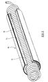
- Sleeve 10 is placed on a supporting core 12 as already known.
- Sleeve 10 comprises an inner layer 14 and an outer layer 16 which, for example, are made by co-extrusion.
- the inner layer 14 is of an insulating material which also has a dielectric constant of ⁇ 3.
- the outer layer 16 is made of a suitable semi-conductive material.
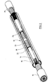
- FIG 3 it is shown how sleeve 10 is placed on a cable connection.
- the cables 18, 20 include conductors 22, 24 which are interconnected through a connector 26 in a conventional manner.
- the connector area is wrapped by a semi-conductive mastic tape 28 in order to achieve a field equalizing effect in this area.
- the sleeve 10 may be provided with a central electrode of a conductive or semi-conductive material which has been incorporated into the main body. Such an electrode is described in DE-A-39 43 296.
- the thickness of the cable insulation is 4.0 mm for a 10 kV cable and 4.5 mm for a 15 kV cable.
- the following values are achieved for a sleeve 10 according to Figure 2: Relative dielectric constant of inner layer 14 3 Thickness of the inner layer 14 8.5 mm Dielectric strength of inner layer 14 20 kV/mm Dissipation factor 0.0001
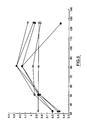
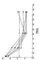
- the graph of Figure 1 represents the relations for an insulating mass used for the inner layer 14 of a sleeve of Figure 2.
- Liquid silicone rubber is matrix material is mixed with metallic coated glass bubbles.
- the abscissa represents the volume percent of glass bubbles in the matrix and the ordinate dielectric properties of the matrix.
- the line marked with the symbol "X" represents volume resistivity in units of ⁇ cm times 10 14
- the line marked with circles represents dielectric strength in units of kV/mm
- the line marked with triangles represents the dielectric constant ⁇ r divided by 10
- the line marked with squares represents the dissipation factor tan d divided by 1000.
- the specific gravity of the glass bubbles is 0.6.
- the glass bubbles are coated with aluminum, with the coating having a thickness of 10 nm (100 Angstroms) while the insulating layer of aluminum oxide coated on the metallic coating has a thickness of 4nm (40 Angstroms).
- the graph of Figure 1 reveals that the specific resistivity is constant above 2% by volume and has a value in the order of 6 x 10 13 ⁇ cm.
- the dielectric strength in the range of 18 kV/mm which is particularly satisfactory for the medium voltage range.
- the dissipation factor is about 0.0001.
- the relative dielectric constant is somewhat above 3 while it is 4 at a volume content of 10%.
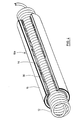
- the sleeve 10a Of Figure 4 differs from that. of Figure 2 in that an additional insulating layer 30 is located between the insulating inner layer 14 and a shielding layer 16.
- Sleeve 10a can be made by co-extrusion or by a successive injection molding.
- the second insulating layer 30 can be made of a conventional flexible insulating material, e.g. silicone rubber or liquid silicone rubber.
- the inner layer 14 corresponds to that of Figure 2.
- Sleeve 10 of Figure 2 is suited for the medium voltage range up to 15 kV, while the sleeve of Figure 4 can be used for medium voltages above 15 kV.
- compositions can be provided:
- the main properties namely the relative dielectric constant and the dielectric strength, can be varied within certain limits by selecting the diameter range of the glass bubbles, the thickness of the aluminum coating and the concentration of the glass bubbles in the matrix material.
- Glass bubbles were obtained having different thickness of the aluminum coating, namely, 2.36 nm (23.6 Angstroms), 4.43 nm (44.3 Angstroms), 6.38 nm (63.8 Angstroms), 13.22 nm (132.2 Angstroms) and 16.00 nm (160.0 Angstroms).
- these glass bubbles were sieved yielding the following diameters, 0-32 ⁇ m (microns), 32-50 ⁇ m, 50-80 ⁇ m and 80-125 ⁇ m.
- the samples were prepared in the following manner:
- the slabs were then post cured for 4 hours at 200° C.
- Figure 5 shows the dependence of the dielectric constant on the size distribution of the glass bubbles.
- the abscissa is sieve mesh in ⁇ m and the ordinate is dielectric constant.
- the line marked with filled squares represents an aluminum coating on the glass bubbles of 2.36 nm (23.6 Angstroms), the filled diamonds 4.43 nm (44.3 Angstroms), the filled triangles 6.38 nm (63.8 Angstroms), the open squares 12.32 nm (123.2 Angstroms), the open diamonds 16.0 nm (160 Angstroms), and the open triangles 16.0 nm (160 Angstroms) unsieved.
- the measurement points were placed on the upper limit of the sieving range (e.g.
- the values at 32 ⁇ m represent glass bubbles in the range of 0-32 ⁇ m, etc.) It can be seen that the dielectric constant increases up to the range of 50-80 ⁇ m with a weak dependence on the thickness of the aluminum coating. For comparative reasons the value for unsieved glass bubbles with a coating thickness of 16.0 nm (160 Angstroms) is indicated which essentially corresponds to the material used in Figure 1.
- the coating thickness should not be too small and preferably be in the range of 4.0-6.0 nm (40-60 Angstroms).
- Figure 6 shows the corresponding relationship for the dielectric strength.
- the abscissa represents sieve mesh in ⁇ m and the ordinate dielectric strength in kV/mm.
- the line marked with filled squares represents an aluminum coating on the glass bubbles of 2.36 nm (23.6 Angstroms), the filled diamonds 4.43 nm (44.3 Angstroms), the filled triangles 6.38 nm (63.8 Angstroms), the open squares 12.32 nm (123.2 Angstroms), the open diamonds 16.0 nm (160 Angstroms), and the open triangles 16.0 nm (160 Angstroms) unsieved.
- the opposite trend can be observed, namely a reduction when moving to larger particles.
- a stable situation is reached when using glass bubbles ranging above 80 ⁇ m.
- the influence of the coating thickness is also moving in the opposite direction yielding the best values at 2.36 nm (23.6 Angstroms).
- the unsieved fraction is indicated.
- the abscissa represents percent weight of glass bubbles in the matrix and the ordinate dielectric constant.
- the line marked with filled squares represents an aluminum coating on the glass bubbles of 2.36 nm (23.6 Angstroms), the filled diamonds 4.43 nm (44.3 Angstroms), the filled triangles 6.38 nm (63.8 Angstroms), the open squares 12.32 nm (123.2 Angstroms), and the open diamonds 16.0 nm (160 Angstroms).
- Figure 7 demonstrates that the dependence of the coating thickness of the glass bubbles is rather weak and that the main determining factor for the dielectric constant is the percent weight of the glass bubbles.
- the abscissa represents percent weight of glass bubbles in the matrix, the ordinate on the left side represents dielectric constant, and the ordinate on the right side represents dielectric strength in kV/mm.
- the line marked with filled squares represents an aluminum coating on the glass bubbles of 2.36 nm (23.6 Angstroms), the filled diamonds 4.43 nm (44.3 Angstroms), the filled triangles 6.38 nm (63.8 Angstroms), the open squares 12.32 nm (123.2 Angstroms), the open diamonds 16.0 nm (160 Angstroms), and the open triangles the average value of dielectric constant taken from Figure 7 for comparison.
- Figure 8 shows that this is not the case for the dependence of the dielectric strength, the values of which are marked on the right side of the diagram.
- the smaller the aluminum coating thickness is, the better the dielectric strength which can be obtained.
Landscapes
- Physics & Mathematics (AREA)
- Spectroscopy & Molecular Physics (AREA)
- Chemical & Material Sciences (AREA)
- Dispersion Chemistry (AREA)
- Cable Accessories (AREA)
- Insulating Bodies (AREA)
- Compositions Of Macromolecular Compounds (AREA)
- Organic Insulating Materials (AREA)
Description
| Relative dielectric constant of | 3 |
| Thickness of the | 8.5 mm |
| Dielectric strength of | 20 kV/mm |
| Dissipation factor | 0.0001 |
| Sieve Size (µm) | Percent Passing Through Sieve |
| 88 | 100 |
| 62 | 93.7 |
| 44 | 73.7 |
| 31 | 50.5 |
| 22 | 30.5 |
| 16 | 15.8 |
| 11 | 7.4 |
| 7.8 | 2.1 |
| 5.5 | 0.0 |
10 parts carbon black N 765
0.9 parts dicumyl peroxide The following electrophysical properties are achieved:
- Relative dielectric constant εr =
- 4.6
- Resistivity: =
- 3 x 10¹⁴ Ωcm
- Dielectric strength: =
- 10 kV/mm
- Relative dielectric constant εr =
- 3.5
- Resistivity: =
- 5 x 10¹⁴ Ωcm
- Dielectric strength: =
- 12 kV/mm
Claims (28)
- Cylindrical radially shrinkable sleeve (10, 10a) for enclosing a connection or an end termination of an electrical cable (18, 20), in particular for a medium voltage cable, having insulation surrounded by a shielding layer, said sleeve (10, 10a) comprising an outer shielding layer (16) of semi-conductive material, and at least one insulation layer (14) on the inner side of said shielding layer, with the unit of said cylindrical layers made of permanently flexible material adapted to be retained in a radially expanded state by mechanical support means (12),
characterized in that the radially innermost insulation layer (14) also provides a stress control and consists of a homogeneous material havinga) a relative dielectric constant > 3 andb) dielectric strength of at least 10 kV/mm. - Cylindrical radially shrinkable sleeve (10, 10a) for enclosing a connection or an end termination of an electrical cable (18, 20), in particular for a medium voltage cable, having insulation surrounded by a shielding layer, said sleeve (10, 10a) comprising an outer shielding layer (16) of semi-conductive material and at least one insulation layer (14) on the inner side of said shielding layer (16), with the unit of said cylindrical layers made of permanent flexible material adapted to be retained in a radially expanded state by mechanical support means (12),
characterized in that the radially innermost insulation layer (14) comprises a matrix of dielectric plastic material and a content of microspheres conductive at least at the surface thereof and having a diameter distribution of between 10 and 500 µm, said microspheres being uniformly distributed in said matrix material, with the mixture having:a) a relative dielectric constant equal to or larger than 3 andb) a dielectric strength of at least 5 kV/mm. - The sleeve of claim 1 or 2, characterized in that a single inner layer (14) is provided.
- The sleeve of claim 2, characterized in that silicone rubber is said matrix material.
- The sleeve of claim 2, characterized in that the diameters of said spheres differ from each other by not more than one order of magnitude.
- The sleeve of claim 5, characterized in that the diameter distribution of said microspheres is between 10 and 90 µm, preferably between 30 and 60 µm.
- The sleeve of claim 2, characterized in that said microspheres are metal spheres.
- The sleeve of claim 2, characterized in that said microspheres are glass spheres being coated with a metal.
- The sleeve of claim 8, characterized in that said coating is of aluminum, nickel, silver or the like.
- The sleeve of claim 2, characterized in that said spheres are coated with a thin insulating layer, preferably by aluminum sub oxide.
- The sleeve of claim 8 or 9, characterized in that the thickness of said coating is about 0.001 µm.
- The sleeve of claim 10, characterized in that the thickness of said insulating layer is about 0.0004 µm.
- The sleeve of claim 2, characterized in that the content of said microspheres is between 2 and 12% by volume, relative to said matrix material.
- The sleeve of claim 2, characterized in that the relative dielectric constant is between 3 and 10.
- The sleeve of claim 2, characterized in that the dissipation factor is less than 0.01.
- The sleeve of claim 1, characterized in that said radially innermost layer is methylvinyl silicone rubber.
- Electrically insulating, moldable mass having field control properties, in particular for the use in the medium voltage range, comprising a matrix of dielectric plastic material and a percentile share of microspheres electrically conductive either totally or at the outer surface thereof and having a diameter between 10 and 500 µm, said microspheres being uniformly mixed into said matrix material, with said compound havinga) a dielectric constant equal to or larger than 3 andb) a dielectric strength of at least 5 kV/mm.
- The mass of claim 17, characterized in that the relative dielectric constant is between 3 and 10, preferably between 3 and 4.
- The mass of claim 17, characterized in that the dielectric strength is at least 10 kV/mm.
- The mass of claim 17, characterized in that the dissipation factor is < 0.01, preferably < 0.001.
- The mass of claim 17, characterized in that the diameters of said spheres do not differ by more than one order of magnitude.
- The mass of claim 17, characterized in that the diameter distribution of said spheres is between 10 and 90 µm, preferably between 30 and 60 µm.
- The mass of claim 17, characterized in that metallic spheres are used or metal-coated glass spheres, preferably hollow glass spheres (glass bubbles).
- The mass of claim 23, characterized in that said coating consists of aluminum nickel, silver or the like, preferably with a thickness of about 0.001 µm.
- The mass of claim 24, characterized in that said spheres are coated with a thin insulating layer, preferably with aluminum oxide, preferably with a thickness of about 0.0004 µm.
- The mass of claim 17, characterized in that the content of said microspheres is between 2 and 20% by volume relative to said matrix material.
- The mass of claim 17, characterized in that silicone rubber is used as matrix material.
- The sleeve of claim 1, characterized in that a central electrode of a conductive or semi-conductive material is incorporated in the unit of cylindrical layers (14, 16).
Applications Claiming Priority (5)
| Application Number | Priority Date | Filing Date | Title |
|---|---|---|---|
| DE4417364 | 1994-05-18 | ||
| DE19944417363 DE4417363A1 (en) | 1994-05-18 | 1994-05-18 | Radially shrinkable cylindrical sleeve for cable connections or cable ends |
| DE4417363 | 1994-05-18 | ||
| DE4417364A DE4417364A1 (en) | 1994-05-18 | 1994-05-18 | Electrically insulating deformable substance |
| PCT/US1995/006125 WO1995031845A1 (en) | 1994-05-18 | 1995-05-17 | Cylindrical radially shrinkable sleeve for an electrical cable and composition thereof |
Publications (3)
| Publication Number | Publication Date |
|---|---|
| EP0760176A1 EP0760176A1 (en) | 1997-03-05 |
| EP0760176B1 true EP0760176B1 (en) | 1998-06-24 |
| EP0760176B2 EP0760176B2 (en) | 2002-10-09 |
Family
ID=25936671
Family Applications (1)
| Application Number | Title | Priority Date | Filing Date |
|---|---|---|---|
| EP95919851A Expired - Lifetime EP0760176B2 (en) | 1994-05-18 | 1995-05-17 | Cylindrical radially shrinkable sleeve for an electrical cable and composition thereof |
Country Status (7)
| Country | Link |
|---|---|
| EP (1) | EP0760176B2 (en) |
| JP (1) | JPH10500835A (en) |
| CA (1) | CA2188430C (en) |
| DE (1) | DE69503131T3 (en) |
| ES (1) | ES2117868T5 (en) |
| MX (1) | MX9605413A (en) |
| WO (1) | WO1995031845A1 (en) |
Families Citing this family (14)
| Publication number | Priority date | Publication date | Assignee | Title |
|---|---|---|---|---|
| US5844170A (en) * | 1996-03-01 | 1998-12-01 | Minnesota Mining And Manufacturing Company | Closure with flowable material and reinforcing core |
| WO1999021259A1 (en) * | 1997-10-22 | 1999-04-29 | Minnesota Mining And Manufacturing Company | Improved medium voltage branch splice and method of making the same |
| US6103975A (en) * | 1998-06-29 | 2000-08-15 | 3M Innovative Properties Company | Pre-assembled electrical splice component |
| US6958548B2 (en) * | 2003-11-19 | 2005-10-25 | Freescale Semiconductor, Inc. | Semiconductor device with magnetically permeable heat sink |
| EP1815485B1 (en) * | 2004-11-11 | 2010-07-21 | Koninklijke Philips Electronics N.V. | Electrical high voltage generator |
| RU2379803C1 (en) | 2006-05-05 | 2010-01-20 | 3М Инновейтив Пропертиз Компани | Cable tubular connector assembly |
| EP1852949B1 (en) | 2006-05-05 | 2009-12-02 | 3M Innovative Properties Company | Tubular terminal for a cable |
| CN101340035B (en) | 2007-07-02 | 2010-08-25 | 3M创新有限公司 | Adapter, cable connector having the adapter and cable connector component |
| CN101388536B (en) * | 2007-09-11 | 2013-05-29 | 3M创新有限公司 | Connector sleeve and cable connector component having the same |
| MX2011011088A (en) | 2009-05-01 | 2011-11-04 | 3M Innovative Properties Co | Cold-shrink separable connector. |
| WO2012155934A1 (en) | 2011-05-19 | 2012-11-22 | Prysmian S.P.A. | Termination for electrical cables and method for manufacturing such a termination |
| PL2608338T3 (en) | 2011-12-21 | 2014-04-30 | 3M Innovative Properties Co | Terminal connection device for a power cable |
| WO2014209739A1 (en) | 2013-06-26 | 2014-12-31 | 3M Innovative Properties Company | Power cable terminal connection device |
| KR102238971B1 (en) * | 2014-02-21 | 2021-04-12 | 엘에스전선 주식회사 | Termination connection box for DC cable |
Family Cites Families (12)
| Publication number | Priority date | Publication date | Assignee | Title |
|---|---|---|---|---|
| GB1246829A (en) * | 1967-10-27 | 1971-09-22 | Exxon Research Engineering Co | Compositions with controlled electrical properties |
| US3585274A (en) * | 1969-09-15 | 1971-06-15 | Minnesota Mining & Mfg | Relief of dielectric stress in high voltage cable connections |
| US3816639A (en) * | 1973-05-14 | 1974-06-11 | Gen Electric | High voltage cable splice with graded insulation and method of making same |
| US4383131A (en) † | 1978-09-14 | 1983-05-10 | Raychem Limited | Shielded electrical cable joints and terminations and sleeve and method for forming same |
| GB2042818B (en) * | 1979-11-30 | 1983-07-27 | Raychem Gmbh | Enclosures for electrical apparatus |
| US4412029A (en) * | 1981-03-02 | 1983-10-25 | Minnesota Mining And Manufacturing Company | Elastomeric composition for providing electrical stress control |
| AU544611B2 (en) * | 1981-07-17 | 1985-06-06 | Fujikura Cable Works Ltd., The | Power cable joint structure |
| IT1228468B (en) * | 1989-01-16 | 1991-06-19 | Pirelli Cavi Spa | ELEMENT OF A DEVICE FOR MAKING AN ELECTRIC CABLES JOINT, ELECTRIC CABLES JOINT WITH IT OBTAINED AND COATING OF THE CONNECTION OF ELECTRIC CABLES CONDUCTORS FOR THAT JOINT. |
| IT1230014B (en) † | 1989-04-20 | 1991-09-20 | Pirelli Cavi Spa | COATING FOR CABLE JOINTS, ELEMENT OF A DEVICE FOR MAKING CABLE JOINTS AND CABLE JOINTS INCORPORATING THIS COATING. |
| AU6219890A (en) * | 1989-10-16 | 1991-04-18 | Minnesota Mining And Manufacturing Company | Elastomeric covering having conformable interior |
| DE3943296C2 (en) * | 1989-12-29 | 1994-08-11 | Minnesota Mining & Mfg | Sleeve for covering a connection or an end of an electrical cable |
| FR2714543B1 (en) † | 1993-12-23 | 1996-01-19 | Euromold | Device for joining power cables. |
-
1995
- 1995-05-17 CA CA002188430A patent/CA2188430C/en not_active Expired - Fee Related
- 1995-05-17 JP JP7529863A patent/JPH10500835A/en active Pending
- 1995-05-17 ES ES95919851T patent/ES2117868T5/en not_active Expired - Lifetime
- 1995-05-17 DE DE69503131T patent/DE69503131T3/en not_active Expired - Lifetime
- 1995-05-17 MX MX9605413A patent/MX9605413A/en unknown
- 1995-05-17 WO PCT/US1995/006125 patent/WO1995031845A1/en active IP Right Grant
- 1995-05-17 EP EP95919851A patent/EP0760176B2/en not_active Expired - Lifetime
Also Published As
| Publication number | Publication date |
|---|---|
| JPH10500835A (en) | 1998-01-20 |
| CA2188430C (en) | 2006-08-15 |
| MX9605413A (en) | 1997-12-31 |
| ES2117868T3 (en) | 1998-08-16 |
| DE69503131T2 (en) | 1998-11-05 |
| ES2117868T5 (en) | 2003-05-01 |
| EP0760176B2 (en) | 2002-10-09 |
| EP0760176A1 (en) | 1997-03-05 |
| DE69503131D1 (en) | 1998-07-30 |
| WO1995031845A1 (en) | 1995-11-23 |
| DE69503131T3 (en) | 2003-06-05 |
| CA2188430A1 (en) | 1995-11-23 |
Similar Documents
| Publication | Publication Date | Title |
|---|---|---|
| EP0760176B1 (en) | Cylindrical radially shrinkable sleeve for an electrical cable and composition thereof | |
| CA1133079A (en) | Dielectric material for influencing electric fields, and stress control devices made therefrom | |
| US3576387A (en) | Heat shrinkable electromagnetic shield for electrical conductors | |
| RU2540412C2 (en) | Nonlinear permittivity dielectric material | |
| AU682227B2 (en) | Closure for high voltage cable connections | |
| US5756936A (en) | Cylindrical radially shrinkable sleeve for an electrical cable and composition thereof | |
| US6124549A (en) | Electrical stress control | |
| AU637655B2 (en) | Radially shrinkable sleeve for enclosing a connection or a terminal of an electric cable | |
| CN1282203C (en) | Electrical insulators, materials and equipment | |
| US3585274A (en) | Relief of dielectric stress in high voltage cable connections | |
| US20080152898A1 (en) | Varistor-based field control tape | |
| EP0244957A1 (en) | Electrical apparatus for controlling electrical stress | |
| WO2006044076A1 (en) | Method of delivering geometric stress relief element to high voltage cable terminations | |
| CN110235208B (en) | Multilayer stress control article and dry termination for medium and high voltage cable applications | |
| EP1326316B2 (en) | Outdoor termination for a high voltage cable | |
| WO1999021259A1 (en) | Improved medium voltage branch splice and method of making the same | |
| CA1166324A (en) | Electric cable with screen incorporating aligned elongate metal particles | |
| JPS58131610A (en) | Electric bushing and method of producing same | |
| JP3009763B2 (en) | Electromagnetic wave absorbing material using double layer particles | |
| EP0049104A1 (en) | Electric cables comprising a semiconducting screening layer |
Legal Events
| Date | Code | Title | Description |
|---|---|---|---|
| PUAI | Public reference made under article 153(3) epc to a published international application that has entered the european phase |
Free format text: ORIGINAL CODE: 0009012 |
|
| 17P | Request for examination filed |
Effective date: 19961015 |
|
| AK | Designated contracting states |
Kind code of ref document: A1 Designated state(s): DE ES FR GB IT |
|
| 17Q | First examination report despatched |
Effective date: 19970304 |
|
| GRAG | Despatch of communication of intention to grant |
Free format text: ORIGINAL CODE: EPIDOS AGRA |
|
| GRAG | Despatch of communication of intention to grant |
Free format text: ORIGINAL CODE: EPIDOS AGRA |
|
| GRAH | Despatch of communication of intention to grant a patent |
Free format text: ORIGINAL CODE: EPIDOS IGRA |
|
| GRAH | Despatch of communication of intention to grant a patent |
Free format text: ORIGINAL CODE: EPIDOS IGRA |
|
| GRAA | (expected) grant |
Free format text: ORIGINAL CODE: 0009210 |
|
| AK | Designated contracting states |
Kind code of ref document: B1 Designated state(s): DE ES FR GB IT |
|
| REF | Corresponds to: |
Ref document number: 69503131 Country of ref document: DE Date of ref document: 19980730 |
|
| REG | Reference to a national code |
Ref country code: ES Ref legal event code: FG2A Ref document number: 2117868 Country of ref document: ES Kind code of ref document: T3 |
|
| ET | Fr: translation filed | ||
| PLBI | Opposition filed |
Free format text: ORIGINAL CODE: 0009260 |
|
| 26 | Opposition filed |
Opponent name: ALCATEL KABEL BETEILIGUNGS-AG Effective date: 19990306 |
|
| PLBF | Reply of patent proprietor to notice(s) of opposition |
Free format text: ORIGINAL CODE: EPIDOS OBSO |
|
| PLBQ | Unpublished change to opponent data |
Free format text: ORIGINAL CODE: EPIDOS OPPO |
|
| PLAB | Opposition data, opponent's data or that of the opponent's representative modified |
Free format text: ORIGINAL CODE: 0009299OPPO |
|
| R26 | Opposition filed (corrected) |
Opponent name: ALCATEL Effective date: 19990306 |
|
| PLBF | Reply of patent proprietor to notice(s) of opposition |
Free format text: ORIGINAL CODE: EPIDOS OBSO |
|
| PLBF | Reply of patent proprietor to notice(s) of opposition |
Free format text: ORIGINAL CODE: EPIDOS OBSO |
|
| PLBQ | Unpublished change to opponent data |
Free format text: ORIGINAL CODE: EPIDOS OPPO |
|
| PLAB | Opposition data, opponent's data or that of the opponent's representative modified |
Free format text: ORIGINAL CODE: 0009299OPPO |
|
| PLBQ | Unpublished change to opponent data |
Free format text: ORIGINAL CODE: EPIDOS OPPO |
|
| PLAB | Opposition data, opponent's data or that of the opponent's representative modified |
Free format text: ORIGINAL CODE: 0009299OPPO |
|
| PLBQ | Unpublished change to opponent data |
Free format text: ORIGINAL CODE: EPIDOS OPPO |
|
| PLAB | Opposition data, opponent's data or that of the opponent's representative modified |
Free format text: ORIGINAL CODE: 0009299OPPO |
|
| R26 | Opposition filed (corrected) |
Opponent name: ALCATEL Effective date: 19990306 |
|
| R26 | Opposition filed (corrected) |
Opponent name: ALCATEL KABEL BETEILIGUNGS-AG Effective date: 19990306 |
|
| R26 | Opposition filed (corrected) |
Opponent name: ALCATEL KABEL BETEILIGUNGS-AG Effective date: 19990306 |
|
| PLAW | Interlocutory decision in opposition |
Free format text: ORIGINAL CODE: EPIDOS IDOP |
|
| APAC | Appeal dossier modified |
Free format text: ORIGINAL CODE: EPIDOS NOAPO |
|
| APAE | Appeal reference modified |
Free format text: ORIGINAL CODE: EPIDOS REFNO |
|
| REG | Reference to a national code |
Ref country code: GB Ref legal event code: IF02 |
|
| APAC | Appeal dossier modified |
Free format text: ORIGINAL CODE: EPIDOS NOAPO |
|
| PLAW | Interlocutory decision in opposition |
Free format text: ORIGINAL CODE: EPIDOS IDOP |
|
| PUAH | Patent maintained in amended form |
Free format text: ORIGINAL CODE: 0009272 |
|
| STAA | Information on the status of an ep patent application or granted ep patent |
Free format text: STATUS: PATENT MAINTAINED AS AMENDED |
|
| 27A | Patent maintained in amended form |
Effective date: 20021009 |
|
| AK | Designated contracting states |
Kind code of ref document: B2 Designated state(s): DE ES FR GB IT |
|
| REG | Reference to a national code |
Ref country code: ES Ref legal event code: DC2A Date of ref document: 20030103 Kind code of ref document: T5 |
|
| ET3 | Fr: translation filed ** decision concerning opposition | ||
| APAH | Appeal reference modified |
Free format text: ORIGINAL CODE: EPIDOSCREFNO |
|
| PGFP | Annual fee paid to national office [announced via postgrant information from national office to epo] |
Ref country code: FR Payment date: 20100525 Year of fee payment: 16 |
|
| PGFP | Annual fee paid to national office [announced via postgrant information from national office to epo] |
Ref country code: ES Payment date: 20110617 Year of fee payment: 17 |
|
| PGFP | Annual fee paid to national office [announced via postgrant information from national office to epo] |
Ref country code: GB Payment date: 20110511 Year of fee payment: 17 |
|
| PGFP | Annual fee paid to national office [announced via postgrant information from national office to epo] |
Ref country code: IT Payment date: 20110524 Year of fee payment: 17 |
|
| REG | Reference to a national code |
Ref country code: FR Ref legal event code: ST Effective date: 20120131 |
|
| PG25 | Lapsed in a contracting state [announced via postgrant information from national office to epo] |
Ref country code: FR Free format text: LAPSE BECAUSE OF NON-PAYMENT OF DUE FEES Effective date: 20110531 |
|
| PGFP | Annual fee paid to national office [announced via postgrant information from national office to epo] |
Ref country code: DE Payment date: 20120510 Year of fee payment: 18 |
|
| GBPC | Gb: european patent ceased through non-payment of renewal fee |
Effective date: 20120517 |
|
| PG25 | Lapsed in a contracting state [announced via postgrant information from national office to epo] |
Ref country code: IT Free format text: LAPSE BECAUSE OF NON-PAYMENT OF DUE FEES Effective date: 20120517 |
|
| PG25 | Lapsed in a contracting state [announced via postgrant information from national office to epo] |
Ref country code: GB Free format text: LAPSE BECAUSE OF NON-PAYMENT OF DUE FEES Effective date: 20120517 |
|
| REG | Reference to a national code |
Ref country code: ES Ref legal event code: FD2A Effective date: 20130820 |
|
| PG25 | Lapsed in a contracting state [announced via postgrant information from national office to epo] |
Ref country code: ES Free format text: LAPSE BECAUSE OF NON-PAYMENT OF DUE FEES Effective date: 20120518 |
|
| PG25 | Lapsed in a contracting state [announced via postgrant information from national office to epo] |
Ref country code: DE Free format text: LAPSE BECAUSE OF NON-PAYMENT OF DUE FEES Effective date: 20131203 |
|
| REG | Reference to a national code |
Ref country code: DE Ref legal event code: R119 Ref document number: 69503131 Country of ref document: DE Effective date: 20131203 |