EP0757492B1 - Apparatus and method for encoding digital video data - Google Patents
Apparatus and method for encoding digital video data Download PDFInfo
- Publication number
- EP0757492B1 EP0757492B1 EP19960305566 EP96305566A EP0757492B1 EP 0757492 B1 EP0757492 B1 EP 0757492B1 EP 19960305566 EP19960305566 EP 19960305566 EP 96305566 A EP96305566 A EP 96305566A EP 0757492 B1 EP0757492 B1 EP 0757492B1
- Authority
- EP
- European Patent Office
- Prior art keywords
- data
- intraframe
- encoded
- entry point
- frame
- Prior art date
- Legal status (The legal status is an assumption and is not a legal conclusion. Google has not performed a legal analysis and makes no representation as to the accuracy of the status listed.)
- Expired - Lifetime
Links
Images


Classifications
-
- H—ELECTRICITY
- H04—ELECTRIC COMMUNICATION TECHNIQUE
- H04N—PICTORIAL COMMUNICATION, e.g. TELEVISION
- H04N5/00—Details of television systems
- H04N5/76—Television signal recording
- H04N5/91—Television signal processing therefor
- H04N5/92—Transformation of the television signal for recording, e.g. modulation, frequency changing; Inverse transformation for playback
-
- H—ELECTRICITY
- H04—ELECTRIC COMMUNICATION TECHNIQUE
- H04N—PICTORIAL COMMUNICATION, e.g. TELEVISION
- H04N19/00—Methods or arrangements for coding, decoding, compressing or decompressing digital video signals
- H04N19/85—Methods or arrangements for coding, decoding, compressing or decompressing digital video signals using pre-processing or post-processing specially adapted for video compression
- H04N19/89—Methods or arrangements for coding, decoding, compressing or decompressing digital video signals using pre-processing or post-processing specially adapted for video compression involving methods or arrangements for detection of transmission errors at the decoder
-
- G—PHYSICS
- G06—COMPUTING; CALCULATING OR COUNTING
- G06T—IMAGE DATA PROCESSING OR GENERATION, IN GENERAL
- G06T9/00—Image coding
- G06T9/007—Transform coding, e.g. discrete cosine transform
-
- G—PHYSICS
- G11—INFORMATION STORAGE
- G11B—INFORMATION STORAGE BASED ON RELATIVE MOVEMENT BETWEEN RECORD CARRIER AND TRANSDUCER
- G11B27/00—Editing; Indexing; Addressing; Timing or synchronising; Monitoring; Measuring tape travel
- G11B27/005—Reproducing at a different information rate from the information rate of recording
-
- H—ELECTRICITY
- H04—ELECTRIC COMMUNICATION TECHNIQUE
- H04N—PICTORIAL COMMUNICATION, e.g. TELEVISION
- H04N21/00—Selective content distribution, e.g. interactive television or video on demand [VOD]
- H04N21/20—Servers specifically adapted for the distribution of content, e.g. VOD servers; Operations thereof
- H04N21/23—Processing of content or additional data; Elementary server operations; Server middleware
- H04N21/235—Processing of additional data, e.g. scrambling of additional data or processing content descriptors
-
- H—ELECTRICITY
- H04—ELECTRIC COMMUNICATION TECHNIQUE
- H04N—PICTORIAL COMMUNICATION, e.g. TELEVISION
- H04N21/00—Selective content distribution, e.g. interactive television or video on demand [VOD]
- H04N21/40—Client devices specifically adapted for the reception of or interaction with content, e.g. set-top-box [STB]; Operations thereof
- H04N21/43—Processing of content or additional data, e.g. demultiplexing additional data from a digital video stream; Elementary client operations, e.g. monitoring of home network or synchronising decoder's clock; Client middleware
- H04N21/432—Content retrieval operation from a local storage medium, e.g. hard-disk
- H04N21/4325—Content retrieval operation from a local storage medium, e.g. hard-disk by playing back content from the storage medium
-
- H—ELECTRICITY
- H04—ELECTRIC COMMUNICATION TECHNIQUE
- H04N—PICTORIAL COMMUNICATION, e.g. TELEVISION
- H04N21/00—Selective content distribution, e.g. interactive television or video on demand [VOD]
- H04N21/40—Client devices specifically adapted for the reception of or interaction with content, e.g. set-top-box [STB]; Operations thereof
- H04N21/43—Processing of content or additional data, e.g. demultiplexing additional data from a digital video stream; Elementary client operations, e.g. monitoring of home network or synchronising decoder's clock; Client middleware
- H04N21/433—Content storage operation, e.g. storage operation in response to a pause request, caching operations
- H04N21/4334—Recording operations
-
- H—ELECTRICITY
- H04—ELECTRIC COMMUNICATION TECHNIQUE
- H04N—PICTORIAL COMMUNICATION, e.g. TELEVISION
- H04N21/00—Selective content distribution, e.g. interactive television or video on demand [VOD]
- H04N21/40—Client devices specifically adapted for the reception of or interaction with content, e.g. set-top-box [STB]; Operations thereof
- H04N21/43—Processing of content or additional data, e.g. demultiplexing additional data from a digital video stream; Elementary client operations, e.g. monitoring of home network or synchronising decoder's clock; Client middleware
- H04N21/434—Disassembling of a multiplex stream, e.g. demultiplexing audio and video streams, extraction of additional data from a video stream; Remultiplexing of multiplex streams; Extraction or processing of SI; Disassembling of packetised elementary stream
- H04N21/4341—Demultiplexing of audio and video streams
-
- H—ELECTRICITY
- H04—ELECTRIC COMMUNICATION TECHNIQUE
- H04N—PICTORIAL COMMUNICATION, e.g. TELEVISION
- H04N21/00—Selective content distribution, e.g. interactive television or video on demand [VOD]
- H04N21/80—Generation or processing of content or additional data by content creator independently of the distribution process; Content per se
- H04N21/83—Generation or processing of protective or descriptive data associated with content; Content structuring
- H04N21/845—Structuring of content, e.g. decomposing content into time segments
- H04N21/8455—Structuring of content, e.g. decomposing content into time segments involving pointers to the content, e.g. pointers to the I-frames of the video stream
-
- H—ELECTRICITY
- H04—ELECTRIC COMMUNICATION TECHNIQUE
- H04N—PICTORIAL COMMUNICATION, e.g. TELEVISION
- H04N7/00—Television systems
- H04N7/24—Systems for the transmission of television signals using pulse code modulation
- H04N7/52—Systems for transmission of a pulse code modulated video signal with one or more other pulse code modulated signals, e.g. an audio signal or a synchronizing signal
Definitions
- the invention relates to apparatus and method for encoding digital video data and to a record medium having stored thereon variable rate encoded digital video data.
- An illustrative embodiment of the invention relates to apparatus and method for encoding and decoding digital video data which enable low and high-speed reproduction of variable rate encoded digital video data.
- An illustrative embodiment of the record medium stores the data in a particular data structure which enables the low and high speed reproduction thereof.
- MPEG compressed digital video data includes intraframe encoded digital video data ("I-frames”) and interframe encoded digital video data including forward predictive encoded data (“P-frames”) and bi-directionally predictive encoded data (“B-frames”).
- I-frames intraframe encoded digital video data
- P-frames forward predictive encoded data
- B-frames bi-directionally predictive encoded data
- a bit stream of MPEG compressed digital video data generally is divided into groups of pictures (GOPs), and each GOP begins with an I-frame.
- GOPs groups of pictures
- each GOP begins with an I-frame.
- digital video data is MPEG compressed at a fixed rate, for example, when the frame pattern of the GOP is fixed, I-frames periodically occur in the bit stream at known positions thereof and, thus, high speed reproduction of the video data by reproducing only I-frames therein is possible since the general position of each I-frame is known.
- digital video data is MPEG compressed at a variable rate (e.g., the frame pattern of a GOP is variable) I-frames do not occur in the bit stream at known intervals thereof and, thus, high speed reproduction by reproducing only I-frames is difficult.
- One technique for accomplishing higher than normal speed reproduction of MPEG compressed digital video data is to record in each sector that includes an I-frame at the beginning of a GOP therein a flag which indicates the existence of the I-frame, and to record in that sector the sector addresses (i.e., positions) of adjacent sectors that include I-frames therein. Therefore, a relatively slow search speed can be accomplished by reproducing adjacent I-pictures in the bit stream.
- One problem with the above-discussed technique is its general inability to reproduce video data from a record medium in high-speed searching modes wherein it is desirable to successively reproduce I-frames occurring at relatively high intervals of time, for example, every 1, 2, 4, etc. seconds, in the bit stream.
- WO 94/07332 discloses a digital video signal encoding apparatus according to the pre-characterising part of claim 1 hereof.
- the position data added to an entry point packet indicates the positions, with respect to the associated intraframe encoded frame (I-frame), of the three previous entry points and the three following entry points.
- apparatus for encoding a digital video signal comprising
- a record medium comprising:
- encoding apparatus a block diagram of illustrative apparatus for encoding digital video data (hereinafter encoding apparatus) in accordance with the present invention is shown.
- the encoding apparatus is shown as comprising a video encoder 1, and audio encoder 2, a multiplexing circuit 3 and a digital storage memory (DSM) 10.
- a digital video signal supplied to a video input terminal is supplied to video encoder 1 which compression encodes (i.e., intraframe and interframe encodes) the video signal in a manner well known in the art and which supplies the encoded video data to a video entry point detection circuit included in multiplexer 3.
- An digital audio signal supplied to an audio input terminal is supplied to audio encoder 2 which encodes the audio data therein in a manner well known in the art to produce packets of audio data and which supplies the packets of audio data to a code buffer 5 included in multiplexer 3.
- video encoder 1 supplies to a controller 8 an entry point ID signal at each output from the video encoder of an I-frame (intracoded frame) of video data.
- Multiplexer 3 is comprised of code buffers 4 and 5, a switching circuit 6, a header appending circuit 7, controller 8, a multiplex system clock generator 9, video entry point detection circuit 31 (hereinafter entry point detector 31), an entry sector generating circuit 32 and an entry point storage memory 33.
- Entry point detector 31 detects the occurrence of an I-frame in the bit stream supplied thereto and supplies to controller 8 another entry point ID signal which indicates the occurrence of an I-frame.
- the entry point ID signals supplied to controller 8 from both video encoder 1 and entry point detector 31 are redundant signals, under certain circumstances, video encoder 1 will not generate the entry point ID signal, for example, as when pre-encoded video data is supplied thereto. Alternatively, video encoder 1 does not supplies the entry point ID signal to control 8. In either case, the occurrence of each I-frame in the bit stream output from entry point detector 31 and which is supplied to code buffer 4 is known.
- Code buffer 4 stores the bit stream data supplied thereto and outputs the stored data to a terminal E1 of switch 6.
- code buffer 5 stores the packets of audio data therein and supplies the stored audio data to a terminal E2 of switch 6.
- Controller 8 functions to control switch 6 to switch between terminals E1 and E2 so as to time-divisionally multiplex packets of video and audio data.
- controller 8 controls entry sector generating circuit 32 to generate entry packet data (to be discussed) and controls switch 6 to switch to terminal E3 so as to effectively insert the generated entry packet data in the bit stream immediately prior to the I-frame.
- System clock generator 9 generates a system clock signal which is supplied to controller 8 which utilizes the supplied signal for purposes of controlling switch 6 to switch between its input terminals E1 - E3.
- Switch 6 supplies the time-divisionally multiplex data to header appending circuit 7 which, in response to a control signal from controller 8, adds a video packet header to the beginning of each packet of video data, adds an audio packet header to the beginning of each packet of audio data, and adds a pack header to each data pack.
- Header appending circuit 7 further appends a back header to each data pack so that each data pack is 2048 bytes long and supplies the resultant signal to digital storage memory DSM which stores the digital data therein.
- Entry point storage memory 33 stores therein position data relating to the detected entry points, that is, positions of selected I-frames output from code buffer 4. Entry point storage memory 33 is further discussed below.
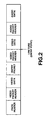
- Fig. 2 illustrates the data structure of a data pack stored in DSM 10.
- the data pack includes a pack header followed by a video packet header, video data, an entry packet, another video packet header, video data, an audio packet header and audio data.
- the pack header includes various information including a pack start code, SCR data, multiplexing rate data, etc.
- the first video packet header and video data immediately following the pack header represent a packet of video data that does not include an I-frame therein since an entry packet has not been inserted-before the first video packet header. However, an entry packet (also called entry data packet herein) precedes the next video packet header and, thus, the ensuing video data includes an I-frame.
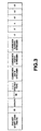
- the data structure of an entry packet is shown in Fig. 3.
- the entry packet includes a packet start code prefix followed by the stream ID data of Oxbf (hexadecimal), length data which identifies the length (i.e., data amount) of the successive packet, "****" ID data (default is FFh) which indicates that the entry packet is specific for a particular person, "****" packet type which indicates the type of classification if the entry packet is specific for a particular person, "current# data streams” data which identifies the number of data sectors that occur before the next entry sector, "current# video streams” data which identifies the number of video sectors that occur before the next entry sector, and "current# audio streams” data which identifies the number of audio sectors that occur before the next entry sector.
- the entry packet further includes "-3", "-2", “-1”, “+1”, “+2” and "+3" entry packet data which identify the locations of 6 different "entry points" corresponding to the beginning positions of 6 different I-frames in the data stream.
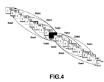
- Fig. 4 a schematic illustration of successive I-frames in the encoded bit stream is shown (the P-frames and B-frames are not shown for convenience) wherein the entry packet stored with (i.e., immediately prior to) each I-frame identifies the locations of 6 different I-frames.
- the "-3", "-2” and "-1" entry packet data identify the beginning locations of 3 I-frames that occur at 3 different predetermined intervals of time prior to the I-frame in which the entry packet is stored.
- the "+1", "+2" and "+3" entry packet data identify the beginning locations of 3 I-frames that occur at the 3 different predetermined intervals of time after the I-frame in which the entry packet is stored. If the 3 different predetermined intervals of time are, for example, 1 second, 2 seconds and 4 seconds, respectively, then the entry packet stored with I-frame 109 identifies the relative locations (relative to I-frame 109) of I-frames 100, 103, 106, 112, 114 and 117, as shown in Fig. 4.
- frame 100 occurs 4 seconds before I-frame 109
- frame 103 occurs 2 seconds before I-frame 109
- frame 106 occurs 1 second before I-frame 109
- I-frame 112 occurs 1 second after I-frame 109
- I-frame 114 occurs 2 seconds after I-frame 109
- I-frame 117 occurs 4 seconds after I-frame 109.
- the entry packet stored with I-frame 110 identify I-frames 108, 105 and 101 which occur 1, 2 and 4 seconds, respectively, before I-frame 110, and also identify I-frames 113, 116 and 119 which occur 1, 2 and 4 seconds, respectively, after I-frame 110.
- Each of the entry packet data "-3", “-2”, ..., "+3" identifies the number of sectors between the current I-frame and the entry point (see Fig. 2) of the respective identified I-frame.
- the predetermined different intervals of time may be different from that shown in Fig. 4.
- the intervals of time 1, 3 and 9 seconds may be used.
- the intervals of time may be varied depending on various properties of the video picture and may vary within the video picture itself. For example, time intervals may be relatively short for a group of images in which the motion therein is large and may be relatively large for a group of images if the motion therein is small.
- an entry sector (i.e., entry packet), which includes the data shown in Fig. 3, is generated by entry sector generator 32 in response to the occurrence of an I-frame (i.e., current I-frame), as previously discussed.
- I-frame i.e., current I-frame
- the entry packet data -3, -2 and -1 can be generated since the positions of I-frames that precede the current frame are known (i.e., they have already occurred in the bit stream).
- Entry point storage memory 33 stores the absolute positions of each entry point (i.e., the beginning of each I-frame) in the bit stream, and entry sector generator 32 is operable to generate relative position data identifying the 3 I-frames that occur before the current frame by using the absolute position of those I-frames stored in memory 33 and the known position of the current frame.
- entry packet data +1, +2 and +3 in entry sector generator 32 and the bit stream including the video and audio data and each of the entry packets (having the dummy data therein) is stored in DSM 10.
- controller 8 At the end of the bit stream (i.e., after all of the video, audio and entry packets are stored in DSM 10), controller 8 ascertains the values of entry packet data +1, +2 and +3 for every one of the entry packets using the positions of each of the entry points (i.e., I-frames) stored in memory 33, and stores the entry packet data +1, +2 and +3 of every entry packet in the appropriate location of DSM 10.
- the digital video data may be variable-bit encoded (e.g., the frame pattern of a GOP is variable).
- an I-frame may not occur at constant intervals in the bit stream and, thus, if a desired interval of time is, for example, 1 second, the encoding apparatus of the present invention cannot assume that the same number of frames (I, P and B-frames) occur between I-frames that are approximately 1 second apart from one another. It is therefore necessary to ensure that each I-frame to which entry packet data of a current frame refers is as closest to the desired time interval as possible.
- Fig. 5 is a flowchart of an operation of controller 8 for identifying the appropriate I-frame to which each entry packet data refers in accordance with the present embodiment. It is noted that controller 8 operates to execute the flowchart of Fig. 5 twice, once when the bit stream is being output from video encoder 1 and subsequently stored in DSM 10 to ascertain the positions of the entry points of I-frames that precede the current frame, and a second time after the bit stream is fully stored in DSM 10 so as to ascertain the positions of the entry points of I-frames that follow each current frame.
- I-frame i.e., current frame
- the position (PCT) of a selected frame that precedes the current frame by 30 frames, which corresponds to a frame that occurs 1 second before the current frame, is ascertained at instruction S101. Since entry points should refer only to I-frames, inquiry S102 determines whether the selected frame is an I-frame. If the selected frame is an I-frame, the beginning position (i.e., the entry point) of the selected frame relative to the current frame is stored as the entry packet data -1 of the entry packet that is stored with (i.e., immediately preceding) the current frame at instruction S104.
- the selected frame is not an I-frame
- the position of a frame that is adjacent to (either before or after) the selected frame in the bit stream is selected as the new selected frame at instruction S103, and then it is determined if the new selected frame is an I-frame at inquiry S102.
- the result of steps of S102 and S103 is a selection of an I-frame that is closest in time to the desired 1 second time interval from the current frame.
- the position (PCT) of a selected second frame that precedes the current frame by 60 frames, which corresponds to a frame that occurs 2 seconds before the current frame, is ascertained at instruction S105. Similar to inquiry S102 and instruction S103, inquiry S106 determines whether the selected second frame is an I-frame, and the position of a frame that is adjacent to the selected second frame in the bit stream is selected as the new selected second frame at instruction S107. When the selected second frame is an I-frame, the beginning position of the selected second frame relative to the current frame is stored as the entry packet data -2 of the entry packet of the current frame at instruction S108.
- Steps 109 through 112 operate in a similar fashion to both sets of steps S101 to S104 and steps S105 to S108, except that an I-frame that precedes the current frame by 120 frames initially is selected, which corresponds to a frame that occurs approximately 4 seconds before the current frame. The beginning position of the selected third frame relative to the current frame then is stored as the entry packet data -3 of the entry packet of the current frame at instruction S112.
- I-frames that occur at times less than 900 milliseconds (ms), 2700 ms and 9000 ms from the current I-frame are not referred to in entry packet data of the current frame.
- next entry point is the first I-picture of a GOP
- the beginning of the GOP is detected by the group start code included in the GOP.
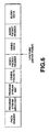
- Fig. 6 illustrates the data structure of the entry sector, that is, a data pack in which an I-frame is included, in accordance with another illustrative embodiment of the present invention.
- the entry sector includes a pack header which includes therein a pack start code, SCR data and MUX rate data.
- the pack header is followed by a program stream directory, a program stream map, a pack other than a video pack, a video packet header, video data including an I-frame, an audio packet header, and audio data.
- the data occurs in a pre-set sequence from the beginning of the sector, thus facilitating data handling.
- Fig. 9 is a block diagram of apparatus for encoding digital video data in accordance with another illustrative embodiment of the present invention, wherein a map information storage device 35 is included in multiplexer 3 which receives information from an external entry device (not shown). All elements of the apparatus of Fig. 9, except device 35, are included in the encoding apparatus of Fig. 1 and, therefore, description thereof is omitted herein. Information stored in device 35 is read therefrom and stored as an entry sector each time it constitutes an entry sector. If the information utilizes a future entry sector position, the entry sector position is read from device 33 after the entire bit stream is stored in DSM 10.
- Fig. 10 is a block diagram of illustrative apparatus for decoding digital video data encoded in accordance with the present invention.
- the decoding apparatus of Fig. 10 decodes data stored in DSM 10 having the data structure shown in Fig. 2.
- the decoding apparatus is comprised of a separation device 21, a video decoder 25 and an audio decoder 26.
- the encoded digital data is read from DSM 10 and supplied to a header separation circuit 22 which separates each pack header, each packet header and each entry packet from the read out data and supplies the separated data to controller 24.
- Header separation circuit 22 also supplies the time-divisionally multiplexed data to an input terminal G of a switching circuit 23 which demultiplexes the data (in response to a control signal from controller 24) by supplying video data therein to a terminal H1 and supplying audio data therein to a terminal H2.
- the video data is supplied to video decoder 25 and the audio data is supplied to audio decoder 26 which decode the respective data in manners well known in the art.
- Controller 24 supplies the entry packet data to entry point storage device 24 which stores the supplied data therein.
- DSM 10 supplies to controller 24 readout position information identifying the position in the bit stream of that data supplied to header separation circuit 24.
- a main controller (not shown) supplies appropriate control signals to controller 24, video decoder 25 and audio decoder 26 so that they operate in a particular search mode.
- controller 24 controls DSM 10 to read out the closest I-frame identified by the data stored in device 41, if available. All of the entry points may be pre-stored (e.g., upon power-up) in device 41 (by reproducing the entire bit stream) prior to reproducing in the search mode. As previously discussed, an entry packet is located immediately before each I-frame and, thus, an I-frame is readably obtained.
- DSM 10 reads out the I-frame including the entry packet that is stored immediately therebefore.
- Separation device 21 along with video decoder 25 operate to decode the I-frame and supply the decoded image data at the video output terminal. While the decoding apparatus is in the search mode, the output of audio decoder 26 is muted. While decoding the read out I-frame, controller 24 ascertains the position in DSM 10 of the next I-frame to be read out.
- the entry packet includes therein the positions of 6 different I-frames relative to the position of the currently read out I-frame, and depending on which search mode is selected, the position of one of those 6 different I-frames is ascertained in controller 24.
- Digital data is picked up from an optical disk 60 by pickup device 61 in response to a control signal supplied from a tracking servo device 70.
- a controller 67 supplies a control command to a drive control circuit 69 which produces a drive signal and which supplies the drive signal to tracking servo device 70.
- a data pack is read from the optical disk and supplied to demodulation circuit 62 which demodulates the signal and supplies a demodulated signal to ECC circuit 63 which detects and corrects errors in the supplied signal.
- the signal then is supplied to demultiplexer 64 which supplies video data therein to a video decoder 65, supplies audio data therein to an audio decoder 66 and supplies TOC information to controller 67.
- TOC information generally is stored in the first reproduced sector.
- Controller 67 supplies the TOC information to TOC storage device 68 which stores the TOC information therein. Further, controller 67 causes a display (not shown) to indicate to a user that the TOC data is loaded.
- drive controller 69 drives via tracking servo circuit 70 the pickup device 61 to reproduce data from disk 60 at a position indicated by the user.
- controller 67 controls video decoder 65 and audio decoder 66 to prepare for decoding.
- demodulation circuit 62 supplies the demodulated reproduced data to an entry point detection circuit 90 which extracts entry point data (e.g., an entry packet) therefrom and supplies the extracted data to subcode CRC circuit 91 which corrects errors therein.
- entry point data e.g., an entry packet
- subcode CRC circuit 91 which corrects errors therein.
- the positions of the entry points of the I-frames identified in the entry point data are stored in entry point buffer 92.
- Controller 67 reads out the data of the next entry point from the entry point buffer 92 and supplies the read-out information to an entry point storage device 93 which stores the data therein. Controller 92 is supplied with the information on the current read-out position from drive controller 69 and, thus, the position and contents of the next entry points can be associatively stored in device 93.
- the entry point portions are separated from the data by entry point detection circuit 90 and stored in the entry point buffer 92 for retrieval by controller 67.
- the ensuing video data is an I-frame which is quickly decoded and output.
- the entry packet includes therein the positions of 6 different I-frames relative to the position of the currently read out frame, and depending on the search mode, the position of one of the 6 I-frames is ascertained in controller 24. This operation is similar to that described above with reference to Fig. 10.
Landscapes
- Engineering & Computer Science (AREA)
- Multimedia (AREA)
- Signal Processing (AREA)
- Physics & Mathematics (AREA)
- General Physics & Mathematics (AREA)
- Databases & Information Systems (AREA)
- Discrete Mathematics (AREA)
- Theoretical Computer Science (AREA)
- Television Signal Processing For Recording (AREA)
- Signal Processing For Digital Recording And Reproducing (AREA)
- Compression Or Coding Systems Of Tv Signals (AREA)
- Compression, Expansion, Code Conversion, And Decoders (AREA)
Abstract
Description
- The invention relates to apparatus and method for encoding digital video data and to a record medium having stored thereon variable rate encoded digital video data.
- An illustrative embodiment of the invention relates to apparatus and method for encoding and decoding digital video data which enable low and high-speed reproduction of variable rate encoded digital video data.
- An illustrative embodiment of the record medium stores the data in a particular data structure which enables the low and high speed reproduction thereof.
- As is known, MPEG compressed digital video data includes intraframe encoded digital video data ("I-frames") and interframe encoded digital video data including forward predictive encoded data ("P-frames") and bi-directionally predictive encoded data ("B-frames"). Generally, an I-frame is decoded without using data of other frames, but P and B-frames are decoded utilizing other frames.
- A bit stream of MPEG compressed digital video data generally is divided into groups of pictures (GOPs), and each GOP begins with an I-frame. When digital video data is MPEG compressed at a fixed rate, for example, when the frame pattern of the GOP is fixed, I-frames periodically occur in the bit stream at known positions thereof and, thus, high speed reproduction of the video data by reproducing only I-frames therein is possible since the general position of each I-frame is known. However, when digital video data is MPEG compressed at a variable rate (e.g., the frame pattern of a GOP is variable) I-frames do not occur in the bit stream at known intervals thereof and, thus, high speed reproduction by reproducing only I-frames is difficult.
- One technique for accomplishing higher than normal speed reproduction of MPEG compressed digital video data is to record in each sector that includes an I-frame at the beginning of a GOP therein a flag which indicates the existence of the I-frame, and to record in that sector the sector addresses (i.e., positions) of adjacent sectors that include I-frames therein. Therefore, a relatively slow search speed can be accomplished by reproducing adjacent I-pictures in the bit stream.
- One problem with the above-discussed technique is its general inability to reproduce video data from a record medium in high-speed searching modes wherein it is desirable to successively reproduce I-frames occurring at relatively high intervals of time, for example, every 1, 2, 4, etc. seconds, in the bit stream.
- International (PCT) Patent Application No. WO 94/07332 discloses a digital video signal encoding apparatus according to the pre-characterising part of
claim 1 hereof. In WO 94/07332, the position data added to an entry point packet indicates the positions, with respect to the associated intraframe encoded frame (I-frame), of the three previous entry points and the three following entry points. - According to one aspect of the invention there is provided apparatus for encoding a digital video signal, comprising
- encoding means for variable rate encoding the digital video signal to produce variable rate encoded video data including both intraframe and interframe encoded frames;
- entry point identification means responsive to the presence in the encoded video data of intraframe encoded frames to generate, and add to the encoded data, in association with the irtraframe encoded frames, entry point packets indicating the presence of said intraframe encoded frames, each said entry point packet including position data identifying the positions within the encoded data, with respect to the associated intraframe encoded frame, of other intraframe encoded frames; and
- recording means for recording the encoded video data, having the generated entry point packets added thereto, on a record medium; characterised in that said entry point identification means is so operative that said position data of each said added entry point packet identifies the positions within the encoded data, with respect to the associated intraframe encoded frame, of a plurality of other intraframe encoded frames that are spaced from the associated intraframe encoded frame, beyond those three intraframe encoded frames that are closest to the associated intraframe encoded frame, such that they occur at respective predetermined intervals of time from the associated intraframe encoded frame in a video picture represented by said digital video signal.
-
- According to another aspect of the invention there is provided a method of encoding a digital video signal, comprising
- variable rate encoding the digital video signal to produce variable rate encoded video data including both intraframe and interframe encoded frames;
- in response to the presence in the encoded video data of intraframe encoded frames, generating, and adding to the encoded data, in association with the intraframe encoded frames, entry point packets indicating the presence of said intraframe encoded frames, each said entry point packet including position data identifying the positions within the encoded data, with respect to the associated intraframe encoded frame, of other intraframe encoded frames; and
- recording the encoded video data, having the generated entry point packets added thereto, on a record medium; characterised in that said position data of each said added entry point packet identifies the positions within the encoded data, with respect to the associated intraframe encoded frame, of a plurality of other intraframe encoded frames that are spaced from the associated intraframe encoded frame, beyond those three intraframe encoded frames that are closest to the associated intraframe encoded frame, such that they occur at respective predetermined intervals of time from the associated intraframe encoded frame in a video picture represented by said digital video signal.
-
- According to a third aspect of the invention there is provided a record medium comprising:
- a plurality of variable length video data areas in which variable rate encoded digital video data is stored, said encoded digital video data including a plurality of intraframe and interframe encoded frames each of which is stored in a respective one of the video data areas; and
- a plurality of entry point data packet areas in which entry point data packets are stored, said entry point data packets indicating the presence of video data areas in which associated said intraframe encoded frames are stored, each said entry point data packet including position data identifying the positions within the stored encoded data, with respect to the associated intraframe encoded frame, of other said video data areas in which intraframe encoded frames are stored; characterised in that said position data of each said entry point data packet identifies the positions within the stored encoded data, with respect to the associated intraframe encoded frame, of a plurality of other intraframe encoded frames that are spaced from the associated intraframe encoded frame, beyond those three intraframe encoded frames that are closest to the associated intraframe encoded frame, such that they occur at respective predetermined intervals of time from the associated intraframe encoded frame in a video picture represented by said digital video signal.
-
- A preferred form of the implementation of the invention described hereinbelow seeks to provide:
- apparatus and method for encoding digital video data which overcome the shortcomings of the above-discussed reproducing technique;
- apparatus and method for encoding digital video data which is operable to achieve low and high speed reproduction of compressed digital video data;
- a recording and reproducing technique which operate to achieve both high and low speed reproduction of variable rate compressed digital video data;
- a technique which allows for the reproduction of I-frames temporally occurring at predetermined constant intervals of time; and
- a record medium having compressed digital video data stored thereon which is reproducible at low and high search speeds.
-
- The following detailed description, given by way of example and not intended to limit the present invention solely thereto, will best be appreciated in conjunction with the accompanying drawings, wherein like reference numerals denote like elements and part, in which:
- Fig. 1 is a block diagram of illustrative apparatus for encoding digital video data in accordance with the present invention;
- Fig. 2 illustrates the data structure of a data pack used in an embodiment of the present invention;
- Fig. 3 illustrates the data structure of an entry packet used in an embodiment of the present invention;
- Fig. 4 is a schematic illustration of the location of I-frames and selected entry points thereof in the data stream temporally occurring at various intervals of time;
- Fig. 5 is a flowchart of an illustrative method for detecting and recording the position of selected identified frames in accordance with the present invention;
- Fig. 6 illustrates another data structure of a data pack used in an embodiment of the present invention;
- Fig. 7 is a table of the program stream directory of an entry sector;
- Fig. 8 is a table of the program stream map of an entry sector;
- Fig. 9 is a block diagram of another illustrative apparatus for encoding digital video data in accordance with the present invention;
- Fig. 10 is a block diagram of illustrative apparatus for decoding digital video data encoded in accordance with the present invention;
- Fig. 11 illustrates the data structure of entry point data; and
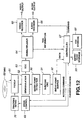
- Fig. 12 is a block diagram of illustrative apparatus for decoding digital video data reproduced from an illustrative record medium in accordance with the present invention.
-
- Referring to the drawings, and particularly to Fig. 1 thereof, a block diagram of illustrative apparatus for encoding digital video data (hereinafter encoding apparatus) in accordance with the present invention is shown. The encoding apparatus is shown as comprising a
video encoder 1, andaudio encoder 2, amultiplexing circuit 3 and a digital storage memory (DSM) 10. A digital video signal supplied to a video input terminal is supplied tovideo encoder 1 which compression encodes (i.e., intraframe and interframe encodes) the video signal in a manner well known in the art and which supplies the encoded video data to a video entry point detection circuit included inmultiplexer 3. An digital audio signal supplied to an audio input terminal is supplied toaudio encoder 2 which encodes the audio data therein in a manner well known in the art to produce packets of audio data and which supplies the packets of audio data to acode buffer 5 included inmultiplexer 3. - In accordance with one aspect of the present
invention video encoder 1 supplies to acontroller 8 an entry point ID signal at each output from the video encoder of an I-frame (intracoded frame) of video data. -
Multiplexer 3 is comprised ofcode buffers switching circuit 6, a header appendingcircuit 7,controller 8, a multiplexsystem clock generator 9, video entry point detection circuit 31 (hereinafter entry point detector 31), an entrysector generating circuit 32 and an entrypoint storage memory 33.Entry point detector 31 detects the occurrence of an I-frame in the bit stream supplied thereto and supplies to controller 8 another entry point ID signal which indicates the occurrence of an I-frame. Although the entry point ID signals supplied tocontroller 8 from bothvideo encoder 1 andentry point detector 31 are redundant signals, under certain circumstances,video encoder 1 will not generate the entry point ID signal, for example, as when pre-encoded video data is supplied thereto. Alternatively,video encoder 1 does not supplies the entry point ID signal to control 8. In either case, the occurrence of each I-frame in the bit stream output fromentry point detector 31 and which is supplied tocode buffer 4 is known. -
Code buffer 4 stores the bit stream data supplied thereto and outputs the stored data to a terminal E1 ofswitch 6. Similarly,code buffer 5 stores the packets of audio data therein and supplies the stored audio data to a terminal E2 ofswitch 6.Controller 8 functions to controlswitch 6 to switch between terminals E1 and E2 so as to time-divisionally multiplex packets of video and audio data. In addition, and in response to the occurrence of an I-frame as indicated by an entry point ID signal from eithercircuit controller 8 controls entrysector generating circuit 32 to generate entry packet data (to be discussed) and controlsswitch 6 to switch to terminal E3 so as to effectively insert the generated entry packet data in the bit stream immediately prior to the I-frame.System clock generator 9 generates a system clock signal which is supplied tocontroller 8 which utilizes the supplied signal for purposes of controllingswitch 6 to switch between its input terminals E1 - E3. - Switch 6 supplies the time-divisionally multiplex data to
header appending circuit 7 which, in response to a control signal fromcontroller 8, adds a video packet header to the beginning of each packet of video data, adds an audio packet header to the beginning of each packet of audio data, and adds a pack header to each data pack. Header appendingcircuit 7 further appends a back header to each data pack so that each data pack is 2048 bytes long and supplies the resultant signal to digital storage memory DSM which stores the digital data therein. - Entry
point storage memory 33 stores therein position data relating to the detected entry points, that is, positions of selected I-frames output fromcode buffer 4. Entrypoint storage memory 33 is further discussed below. - Fig. 2 illustrates the data structure of a data pack stored in
DSM 10. As shown, the data pack includes a pack header followed by a video packet header, video data, an entry packet, another video packet header, video data, an audio packet header and audio data. The pack header includes various information including a pack start code, SCR data, multiplexing rate data, etc. The first video packet header and video data immediately following the pack header represent a packet of video data that does not include an I-frame therein since an entry packet has not been inserted-before the first video packet header. However, an entry packet (also called entry data packet herein) precedes the next video packet header and, thus, the ensuing video data includes an I-frame. - The data structure of an entry packet is shown in Fig. 3. The entry packet includes a packet start code prefix followed by the stream ID data of Oxbf (hexadecimal), length data which identifies the length (i.e., data amount) of the successive packet, "****" ID data (default is FFh) which indicates that the entry packet is specific for a particular person, "****" packet type which indicates the type of classification if the entry packet is specific for a particular person, "current# data streams" data which identifies the number of data sectors that occur before the next entry sector, "current# video streams" data which identifies the number of video sectors that occur before the next entry sector, and "current# audio streams" data which identifies the number of audio sectors that occur before the next entry sector.
- The entry packet further includes "-3", "-2", "-1", "+1", "+2" and "+3" entry packet data which identify the locations of 6 different "entry points" corresponding to the beginning positions of 6 different I-frames in the data stream. Referring to Fig. 4, a schematic illustration of successive I-frames in the encoded bit stream is shown (the P-frames and B-frames are not shown for convenience) wherein the entry packet stored with (i.e., immediately prior to) each I-frame identifies the locations of 6 different I-frames. In accordance with the present invention, the "-3", "-2" and "-1" entry packet data identify the beginning locations of 3 I-frames that occur at 3 different predetermined intervals of time prior to the I-frame in which the entry packet is stored. In addition, the "+1", "+2" and "+3" entry packet data identify the beginning locations of 3 I-frames that occur at the 3 different predetermined intervals of time after the I-frame in which the entry packet is stored. If the 3 different predetermined intervals of time are, for example, 1 second, 2 seconds and 4 seconds, respectively, then the entry packet stored with I-
frame 109 identifies the relative locations (relative to I-frame 109) of I-frames frame 109,frame 103 occurs 2 seconds before I-frame 109,frame 106 occurs 1 second before I-frame 109, I-frame 112 occurs 1 second after I-frame 109, I-frame 114 occurs 2 seconds after I-frame 109, and I-frame 117 occurs 4 seconds after I-frame 109. Similarly, the entry packet stored with I-frame 110 identify I-frames frame 110, and also identify I-frames frame 110. Each of the entry packet data "-3", "-2", ..., "+3" identifies the number of sectors between the current I-frame and the entry point (see Fig. 2) of the respective identified I-frame. The predetermined different intervals of time may be different from that shown in Fig. 4. For example, the intervals of time of 1, 3 and 9 seconds may be used. Further, the intervals of time may be varied depending on various properties of the video picture and may vary within the video picture itself. For example, time intervals may be relatively short for a group of images in which the motion therein is large and may be relatively large for a group of images if the motion therein is small. - It is seen that by identifying entry points representing I-frames located at 3 different intervals of time from a given I-frame (both before and after), both low-speed searching and high-speed searching (and mid-speed searching) can be accomplished, as will be discussed. In addition, as the reproducing speed exponentially increases, for example, from a 10× to a 100× reproducing speed, it is preferable to use entry points (i.e., I-frames) that are located at exponentially increasing temporal distances from a given I-frame. For example, in a 100x reproducing mode, a predetermined time interval of approximately 4 seconds is chosen. At a 30 frame/second frame rate, there are 120 frames in 4 seconds, which is close enough to the desired 100x reproducing speed. However, a 3.3 second time interval can be used if greater precision is required. On the other hand, for very low reproducing search speeds, for example, in a 2x reproducing mode, sequential decoding of I-frames should suffice and, thus, use of entry points may not be necessary.
- Referring back to Fig. 1, an entry sector (i.e., entry packet), which includes the data shown in Fig. 3, is generated by
entry sector generator 32 in response to the occurrence of an I-frame (i.e., current I-frame), as previously discussed. At the time the entry packet is generated, the entry packet data -3, -2 and -1 can be generated since the positions of I-frames that precede the current frame are known (i.e., they have already occurred in the bit stream). Entrypoint storage memory 33 stores the absolute positions of each entry point (i.e., the beginning of each I-frame) in the bit stream, andentry sector generator 32 is operable to generate relative position data identifying the 3 I-frames that occur before the current frame by using the absolute position of those I-frames stored inmemory 33 and the known position of the current frame. - However, the position of entry points corresponding to the beginning locations of I-frames that occur after the current frame are not known at the time the current frame is supplied to switch 6 (i.e., when it occurs in the bit stream). Thus, dummy data is established as entry packet data +1, +2 and +3 in
entry sector generator 32 and the bit stream including the video and audio data and each of the entry packets (having the dummy data therein) is stored inDSM 10. At the end of the bit stream (i.e., after all of the video, audio and entry packets are stored in DSM 10),controller 8 ascertains the values of entry packet data +1, +2 and +3 for every one of the entry packets using the positions of each of the entry points (i.e., I-frames) stored inmemory 33, and stores the entry packet data +1, +2 and +3 of every entry packet in the appropriate location ofDSM 10. - As previously mentioned, the digital video data may be variable-bit encoded (e.g., the frame pattern of a GOP is variable). In this case, an I-frame may not occur at constant intervals in the bit stream and, thus, if a desired interval of time is, for example, 1 second, the encoding apparatus of the present invention cannot assume that the same number of frames (I, P and B-frames) occur between I-frames that are approximately 1 second apart from one another. It is therefore necessary to ensure that each I-frame to which entry packet data of a current frame refers is as closest to the desired time interval as possible.
- Fig. 5 is a flowchart of an operation of
controller 8 for identifying the appropriate I-frame to which each entry packet data refers in accordance with the present embodiment. It is noted thatcontroller 8 operates to execute the flowchart of Fig. 5 twice, once when the bit stream is being output fromvideo encoder 1 and subsequently stored inDSM 10 to ascertain the positions of the entry points of I-frames that precede the current frame, and a second time after the bit stream is fully stored inDSM 10 so as to ascertain the positions of the entry points of I-frames that follow each current frame. - A description of the first time execution of the flowchart of Fig. 5 will be provided. At the occurrence of an I-frame (i.e., current frame), the position (PCT) of a selected frame that precedes the current frame by 30 frames, which corresponds to a frame that occurs 1 second before the current frame, is ascertained at instruction S101. Since entry points should refer only to I-frames, inquiry S102 determines whether the selected frame is an I-frame. If the selected frame is an I-frame, the beginning position (i.e., the entry point) of the selected frame relative to the current frame is stored as the entry packet data -1 of the entry packet that is stored with (i.e., immediately preceding) the current frame at instruction S104. However, if the selected frame is not an I-frame, the position of a frame that is adjacent to (either before or after) the selected frame in the bit stream is selected as the new selected frame at instruction S103, and then it is determined if the new selected frame is an I-frame at inquiry S102. The result of steps of S102 and S103 is a selection of an I-frame that is closest in time to the desired 1 second time interval from the current frame.
- Next, the position (PCT) of a selected second frame that precedes the current frame by 60 frames, which corresponds to a frame that occurs 2 seconds before the current frame, is ascertained at instruction S105. Similar to inquiry S102 and instruction S103, inquiry S106 determines whether the selected second frame is an I-frame, and the position of a frame that is adjacent to the selected second frame in the bit stream is selected as the new selected second frame at instruction S107. When the selected second frame is an I-frame, the beginning position of the selected second frame relative to the current frame is stored as the entry packet data -2 of the entry packet of the current frame at instruction S108.
-
Steps 109 through 112 operate in a similar fashion to both sets of steps S101 to S104 and steps S105 to S108, except that an I-frame that precedes the current frame by 120 frames initially is selected, which corresponds to a frame that occurs approximately 4 seconds before the current frame. The beginning position of the selected third frame relative to the current frame then is stored as the entry packet data -3 of the entry packet of the current frame at instruction S112. - The operation of the flowchart of Fig. 5 is repeated after the entire bit stream is stored in
DSM 10 to ascertain the positions of the entry points of I-frames that occur after the current frames. - Although the flowchart of Fig. 5 provides for the re-selecting of a frame, in inquiries S103, S107 and S111, if an I-frame has not yet been selected, the present invention contemplates that the ultimate selection of an I-frame that occurs at a time interval from a current frame that is considerably different from a desired time interval may be undesirable. Therefore, in one embodiment of the present invention, I-frames that occur before or after the current I-frame by an amount of time that is different from the desired time interval by more than 10% are not referred to by the entry point data of the current I-frame. For example, for the desired time intervals of 1, 3 and 9 seconds, I-frames that occur at times less than 900 milliseconds (ms), 2700 ms and 9000 ms from the current I-frame are not referred to in entry packet data of the current frame.
- If the next entry point is the first I-picture of a GOP, the beginning of the GOP is detected by the group start code included in the GOP. An I-frame which appears first becomes the next entry point.
- Fig. 6 illustrates the data structure of the entry sector, that is, a data pack in which an I-frame is included, in accordance with another illustrative embodiment of the present invention. As shown, the entry sector includes a pack header which includes therein a pack start code, SCR data and MUX rate data. The pack header is followed by a program stream directory, a program stream map, a pack other than a video pack, a video packet header, video data including an I-frame, an audio packet header, and audio data. In this embodiment, the data occurs in a pre-set sequence from the beginning of the sector, thus facilitating data handling.
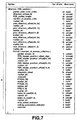
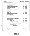
- The program stream directory has a data structure defined by the MPEG standard and is used to specify an accessible position in the data stream. The program stream directory is shown in Fig. 7. A loop "A" in the stream is traversed seven times to record three "forward" and three "backward" I-frames as well as the entry points to the "backward" I-frames. "Forward" and "backward" I-frames herein refer to the I-frames that are identified in the data pack of a current frame. The program stream map is shown in Fig. 8 and, as shown, loops B and C therein include descriptors "()" for accommodating a variety of information data. Information data are included in the descriptors, for example, the number of streams or the information on elementary streams.
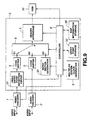
- Fig. 9 is a block diagram of apparatus for encoding digital video data in accordance with another illustrative embodiment of the present invention, wherein a map
information storage device 35 is included inmultiplexer 3 which receives information from an external entry device (not shown). All elements of the apparatus of Fig. 9, exceptdevice 35, are included in the encoding apparatus of Fig. 1 and, therefore, description thereof is omitted herein. Information stored indevice 35 is read therefrom and stored as an entry sector each time it constitutes an entry sector. If the information utilizes a future entry sector position, the entry sector position is read fromdevice 33 after the entire bit stream is stored inDSM 10. - Fig. 10 is a block diagram of illustrative apparatus for decoding digital video data encoded in accordance with the present invention. The decoding apparatus of Fig. 10 decodes data stored in
DSM 10 having the data structure shown in Fig. 2. The decoding apparatus is comprised of aseparation device 21, avideo decoder 25 and anaudio decoder 26. In response to control signals supplied from acontroller 24, the encoded digital data is read fromDSM 10 and supplied to aheader separation circuit 22 which separates each pack header, each packet header and each entry packet from the read out data and supplies the separated data tocontroller 24.Header separation circuit 22 also supplies the time-divisionally multiplexed data to an input terminal G of a switchingcircuit 23 which demultiplexes the data (in response to a control signal from controller 24) by supplying video data therein to a terminal H1 and supplying audio data therein to a terminal H2. The video data is supplied tovideo decoder 25 and the audio data is supplied toaudio decoder 26 which decode the respective data in manners well known in the art. -
Controller 24 supplies the entry packet data to entrypoint storage device 24 which stores the supplied data therein.DSM 10 supplies tocontroller 24 readout position information identifying the position in the bit stream of that data supplied toheader separation circuit 24. - The operation of the decoding apparatus of Fig. 10 operating in a search mode will now be described. A main controller (not shown) supplies appropriate control signals to
controller 24,video decoder 25 andaudio decoder 26 so that they operate in a particular search mode. Upon reproduction in the search mode,controller 24controls DSM 10 to read out the closest I-frame identified by the data stored indevice 41, if available. All of the entry points may be pre-stored (e.g., upon power-up) in device 41 (by reproducing the entire bit stream) prior to reproducing in the search mode. As previously discussed, an entry packet is located immediately before each I-frame and, thus, an I-frame is readably obtained. -
DSM 10 reads out the I-frame including the entry packet that is stored immediately therebefore.Separation device 21 along withvideo decoder 25 operate to decode the I-frame and supply the decoded image data at the video output terminal. While the decoding apparatus is in the search mode, the output ofaudio decoder 26 is muted. While decoding the read out I-frame,controller 24 ascertains the position inDSM 10 of the next I-frame to be read out. As previously discussed, the entry packet includes therein the positions of 6 different I-frames relative to the position of the currently read out I-frame, and depending on which search mode is selected, the position of one of those 6 different I-frames is ascertained incontroller 24. - In a low speed forward search mode, the position of the next I-frame to be reproduced is stored in entry
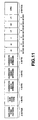
packet data + 1. In a high speed forward search mode, the position of the next I-frame to be reproduced is stored in entrypacket data + 3. In addition, low, medium and high reverse search speeds can be accomplished since the position of the next I-frame to be reproduced is stored in entry packet data -1, -2, and -3 respectively. Fig. 11 illustrates the data structure of an entry packet reproduced fromDSM 10 in accordance with another illustrative embodiment of the present invention. Referring next to Fig. 12, a block diagram of illustrative apparatus for decoding digital video data reproduced from an optical disk in accordance with another embodiment of the present invention is shown. Digital data is picked up from anoptical disk 60 bypickup device 61 in response to a control signal supplied from a trackingservo device 70. Acontroller 67 supplies a control command to adrive control circuit 69 which produces a drive signal and which supplies the drive signal to trackingservo device 70. A data pack is read from the optical disk and supplied todemodulation circuit 62 which demodulates the signal and supplies a demodulated signal toECC circuit 63 which detects and corrects errors in the supplied signal. The signal then is supplied to demultiplexer 64 which supplies video data therein to avideo decoder 65, supplies audio data therein to anaudio decoder 66 and supplies TOC information tocontroller 67. TOC information generally is stored in the first reproduced sector.Controller 67 supplies the TOC information toTOC storage device 68 which stores the TOC information therein. Further,controller 67 causes a display (not shown) to indicate to a user that the TOC data is loaded. - When the reproducing device shown in Fig. 12 begins reproducing video data (in response to an appropriate control signal),
drive controller 69 drives via trackingservo circuit 70 thepickup device 61 to reproduce data fromdisk 60 at a position indicated by the user. At the same time,controller 67controls video decoder 65 andaudio decoder 66 to prepare for decoding. - Data is reproduced from
disk 60 in a manner well known in the art and the reproduced data is demodulated incircuit 62 and supplied toECC circuit 63 which corrects errors therein. The error corrected data is supplied to demultiplexer 64 which, as previously stated, demultiplexes the data and supplies the video and audio data therein to video andaudio decoders - In addition,
demodulation circuit 62 supplies the demodulated reproduced data to an entrypoint detection circuit 90 which extracts entry point data (e.g., an entry packet) therefrom and supplies the extracted data to subcodeCRC circuit 91 which corrects errors therein. The positions of the entry points of the I-frames identified in the entry point data are stored inentry point buffer 92. -
Controller 67 reads out the data of the next entry point from theentry point buffer 92 and supplies the read-out information to an entrypoint storage device 93 which stores the data therein.Controller 92 is supplied with the information on the current read-out position fromdrive controller 69 and, thus, the position and contents of the next entry points can be associatively stored indevice 93. - The operation of the reproducing and decoding apparatus of Fig. 12 operating in a search mode will now be described.
Controller 67 controlsvideo decoder 65 andaudio decoder 66 so that they operate in a particular search mode. Upon reproduction in the search mode,controller 67 controls drivecontrol 69 to causepickup device 61 to read out the entry point that is located near the current read out position, as identified indevice 93.Pickup device 61 reproduces data from the entry point and supplies via the various circuits the reproduced data todemultiplexer 64.Demultiplexer 64 supplies the video data tovideo decoder 65 which decodes and outputs the supplied data. While the reproducing and decoding apparatus of fig. 12 is in the search mode, the output ofaudio decoder 66 is muted. - The entry point portions are separated from the data by entry
point detection circuit 90 and stored in theentry point buffer 92 for retrieval bycontroller 67. As previously mentioned, since reproduction begins at the entry point, the ensuing video data is an I-frame which is quickly decoded and output. - As previously discussed, the entry packet includes therein the positions of 6 different I-frames relative to the position of the currently read out frame, and depending on the search mode, the position of one of the 6 I-frames is ascertained in
controller 24. This operation is similar to that described above with reference to Fig. 10. - While the present invention has been particularly shown and described in conjunction with preferred illustrative embodiments thereof, it will be readily appreciated by those of ordinary skill in the art that various changes may be made without departing from the spirit and scope of the invention. For example, although the time intervals of 1, 2 and 4 seconds, and 1, 3 and 9 seconds is disclosed herein, other time intervals and other number of time intervals, eg. 4 different time intervals may be used in the present invention.
- Therefore, it is intended that the appended claims be interpreted as including the embodiments described herein, the alternatives mentioned above, and all equivalents thereto.
Claims (23)
- Apparatus for encoding a digital video signal, comprisingcharacterised in that said entry point identification means (31, 32, 8, 6) is so operative that said position data of each said added entry point packet identifies the positions within the encoded data, with respect to the associated intraframe encoded frame, of a plurality of other intraframe encoded frames that are spaced from the associated intraframe encoded frame, beyond those three intraframe encoded frames that are closest to the associated intraframe encoded frame, such that they occur at respective predetermined intervals of time from the associated intraframe encoded frame in a video picture represented by said digital video signal.encoding means (1) for variable rate encoding the digital video signal to produce variable rate encoded video data including both intraframe and interframe encoded frames;entry point identification means (31, 32, 8, 6) responsive to the presence in the encoded video data of intraframe encoded frames to generate, and add to the encoded data, in association with the intraframe encoded frames, entry point packets indicating the presence of said intraframe encoded frames, each said entry point packet including position data identifying the positions within the encoded data, with respect to the associated intraframe encoded frame, of other intraframe encoded frames; andrecording means for recording the encoded video data, having the generated entry point packets added thereto, on a record medium (10);
- Apparatus according to claim 1, wherein said entry point identification means (31, 32, 8, 6) is so operative that said position data identifies the position of an intraframe encoded frame located in the encoded video data nearest in time to a frame occurring at one of said predetermined time intervals in the video picture when the frame occurring at said predetermined time interval is not an intraframe encoded frame.
- Apparatus according to claim 2, wherein said entry point identification means (31, 32, 8, 6) is operative to add respective entry point packets to each of the intraframe encoded frames.
- Apparatus according to claim 3, wherein said entry point identification means (31, 32, 8,6) is operative to add a said entry point packet to the beginning of each of the intraframe encoded frames.
- Apparatus according to any one of claims 1 to 4, wherein said plurality of other intraframe encoded frames comprises an intraframe encoded frame preceding and an intraframe encoded frame following the intraframe encoded frame associated with the respective entry point packet.
- Apparatus according to any one of claims 1 to 4, wherein said plurality of intraframe encoded frames comprises intraframe encoded frames occurring at said respective predetermined intervals of time after the intraframe encoded frame associated with the respective entry point packet.
- Apparatus according to claim 6, wherein said plurality of intraframe encoded frames also comprises intraframe encoded frames occurring at said respective predetermined intervals of time before the intraframe encoded frame associated with the respective entry point packet.
- Apparatus according to any one of claims 1 to 7, wherein said respective predetermined intervals of time are 1, 2 and 4 seconds.
- Apparatus according to any one of claims 1 to 7, wherein said respective predetermined intervals of time are 1, 3 and 9 seconds.
- A method of encoding a digital video signal, comprisingcharacterised in that said position data of each said added entry point packet identifies the positions within the encoded data, with respect to the associated intraframe encoded frame, of a plurality of other intraframe encoded frames that are spaced from the associated intraframe encoded frame, beyond those three intraframe encoded frames that are closest to the associated intraframe encoded frame, such that they occur at respective predetermined intervals of time from the associated intraframe encoded frame in a video picture represented by said digital video signal.variable rate encoding (1) the digital video signal to produce variable rate encoded video data including both intraframe and interframe encoded frames;in response to the presence in the encoded video data of intraframe encoded frames, generating, and adding to the encoded data, in association with the intraframe encoded frames, entry point packets indicating the presence of said intraframe encoded frames, each said entry point packet including position data identifying the positions within the encoded data, with respect to the associated intraframe encoded frame, of other intraframe encoded frames; andrecording the encoded video data, having the generated entry point packets added thereto, on a record medium (10);
- A method according to claim 10, wherein said position date identifies the position of an intraframe encoded frame located in the encoded video data nearest in time to a frame occurring at one of said predetermined time intervals in the video picture when the frame occurring at said predetermined time interval is not an intraframe encoded frame.
- A method according to claim 10 or claim 11, wherein respective entry point packets are added to each of the intraframe encoded frames.
- A method according to claim 12, wherein a said entry point packet is added to the beginning of each of the intraframe encoded frames.
- A method according to any one of claims 10 to 14, wherein said plurality of other intraframe encoded frames comprises an intraframe encoded frame preceding and an intraframe encoded frame following the intraframe encoded frame associated with the respective entry point packet.
- A method according to any one of claims 10 to 14, wherein said plurality of intraframe encoded frames comprises intraframe encoded frames occurring at said respective predetermined intervals of time after the intraframe encoded frame associated with respective entry point packet.
- A method according to claim 15, wherein said plurality of intraframe encoded frames also comprises intraframe encoded frames occurring at said respective predetermined intervals of time before the intraframe encoded frame associated with the respective entry point packet.
- A method according to any one of claims 10 to 16, wherein said respective predetermined intervals of time are 1, 2 and 4 seconds.
- A method according to any one of claims 10 to 16, wherein said respective predetermined intervals of time are 1, 3 and 9 seconds.
- A record medium comprising:characterised in that said position data of each said entry point data packet identifies the positions within the stored encoded data, with respect to the associated intraframe encoded frame, of a plurality of other intraframe encoded frames that are spaced from the associated intraframe encoded frame, beyond those three intraframe encoded frames that are closest to the associated intraframe encoded frame, such that they occur at respective predetermined intervals of time from the associated intraframe encoded frame in a video picture represented by said digital video signal.a plurality of variable length video data areas in which variable rate encoded digital video data is stored, said encoded digital video data including a plurality of intraframe and interframe encoded frames each of which is stored in a respective one of the video data areas; anda plurality of entry point data packet areas in which entry point data packets are stored, said entry point data packets indicating the presence of video data areas in which associated said intraframe encoded frames are stored, each said entry point data packet including position data identifying the positions within the stored encoded data, with respect to the associated intraframe encoded frame, of other said video data areas in which intraframe encoded frames are stored;
- A record medium according to claim 19, wherein a respective one of said entry point data packet areas immediately precedes on the record medium each of said video data areas in which intraframe encoded frames are stored.
- A record medium according to claim 20, wherein said plurality of other intraframe encoded frames comprises an intraframe encoded frame preceding and an intraframe encoded frame following the video data area immediately following the entry point packet area in which the respective entry point data packet is stored.
- A record medium according to claim 19, claim 20 or claim 21, wherein said plurality of intraframe encoded frames comprises intraframe encoded frames occurring at said respective predetermined intervals of time after the intraframe encoded frame in the video data area immediately following the entry point data packet area in which the respective entry point data packet is stored.
- A record medium according to claim 19, claim 20 or claim 21, wherein said plurality of intraframe encoded frames also comprises intraframe encoded frames occurring at said respective predetermined intervals of time before the intraframe encoded frame in the video data area immediately following the entry point data packet area in which the respective entry point data packet is stored.
Priority Applications (1)
| Application Number | Priority Date | Filing Date | Title |
|---|---|---|---|
| EP20000202503 EP1039756B1 (en) | 1995-08-02 | 1996-07-30 | Apparatus and method for encoding digital video data |
Applications Claiming Priority (3)
| Application Number | Priority Date | Filing Date | Title |
|---|---|---|---|
| JP19781395 | 1995-08-02 | ||
| JP19781395A JP3484832B2 (en) | 1995-08-02 | 1995-08-02 | Recording apparatus, recording method, reproducing apparatus and reproducing method |
| JP197813/95 | 1995-08-02 |
Related Child Applications (1)
| Application Number | Title | Priority Date | Filing Date |
|---|---|---|---|
| EP20000202503 Division EP1039756B1 (en) | 1995-08-02 | 1996-07-30 | Apparatus and method for encoding digital video data |
Publications (3)
| Publication Number | Publication Date |
|---|---|
| EP0757492A2 EP0757492A2 (en) | 1997-02-05 |
| EP0757492A3 EP0757492A3 (en) | 1997-11-19 |
| EP0757492B1 true EP0757492B1 (en) | 2001-09-12 |
Family
ID=16380777
Family Applications (2)
| Application Number | Title | Priority Date | Filing Date |
|---|---|---|---|
| EP19960305566 Expired - Lifetime EP0757492B1 (en) | 1995-08-02 | 1996-07-30 | Apparatus and method for encoding digital video data |
| EP20000202503 Expired - Lifetime EP1039756B1 (en) | 1995-08-02 | 1996-07-30 | Apparatus and method for encoding digital video data |
Family Applications After (1)
| Application Number | Title | Priority Date | Filing Date |
|---|---|---|---|
| EP20000202503 Expired - Lifetime EP1039756B1 (en) | 1995-08-02 | 1996-07-30 | Apparatus and method for encoding digital video data |
Country Status (13)
| Country | Link |
|---|---|
| US (1) | US6363212B1 (en) |
| EP (2) | EP0757492B1 (en) |
| JP (1) | JP3484832B2 (en) |
| KR (1) | KR100440649B1 (en) |
| CN (1) | CN1130922C (en) |
| AT (2) | ATE205656T1 (en) |
| AU (1) | AU723796B2 (en) |
| CA (1) | CA2181863C (en) |
| DE (2) | DE69615111T2 (en) |
| ES (2) | ES2161331T3 (en) |
| MX (2) | MX9603108A (en) |
| MY (1) | MY117793A (en) |
| TW (1) | TW317064B (en) |
Families Citing this family (61)
| Publication number | Priority date | Publication date | Assignee | Title |
|---|---|---|---|---|
| KR100223163B1 (en) * | 1995-12-11 | 1999-10-15 | 윤종용 | Disc format for multiple speed reproduction and method for multiple speed reproduction of mpeg data thereby, and device thereof |
| EP0954924A4 (en) * | 1997-01-21 | 2003-05-14 | Sarnoff Corp | Information stream syntax for indicating the presence of a splice point |
| US6697566B2 (en) * | 1997-10-17 | 2004-02-24 | Sony Corporation | Encoded signal characteristic point recording apparatus |
| KR100324512B1 (en) * | 1998-07-14 | 2002-06-26 | 구자홍 | Real-time data recording and playback device and its control method |
| US7558472B2 (en) | 2000-08-22 | 2009-07-07 | Tivo Inc. | Multimedia signal processing system |
| US8380041B2 (en) * | 1998-07-30 | 2013-02-19 | Tivo Inc. | Transportable digital video recorder system |
| US6647202B1 (en) * | 1998-07-30 | 2003-11-11 | Matsushita Electric Industrial Co., Ltd. | Video signal reproducing apparatus capable of reproducing bitstreams and video signal reproducing method |
| US6233389B1 (en) * | 1998-07-30 | 2001-05-15 | Tivo, Inc. | Multimedia time warping system |
| US8577205B2 (en) * | 1998-07-30 | 2013-11-05 | Tivo Inc. | Digital video recording system |
| EP2200296B1 (en) | 1999-09-20 | 2018-01-31 | TiVo Solutions Inc. | Closed caption tagging system |
| US7106946B1 (en) * | 1999-09-28 | 2006-09-12 | Sony Corporation | Transport stream processing device, and associated methodology of generating and aligning source data packets in a physical data structure |
| JP4389365B2 (en) * | 1999-09-29 | 2009-12-24 | ソニー株式会社 | Transport stream recording apparatus and method, transport stream playback apparatus and method, and program recording medium |
| US7340153B2 (en) * | 2000-01-11 | 2008-03-04 | Hitachi, Ltd. | Apparatus and method for recording and reproducing information |
| KR100564893B1 (en) * | 2000-06-30 | 2006-03-30 | 가부시끼가이샤 도시바 | Frame information description method and apparatus, frame information generating method and apparatus, special reproducing method and apparatus, apparatus for generating a special reproduction control information, and computer-readable recording medium |
| GB0031221D0 (en) * | 2000-12-21 | 2001-01-31 | Koninkl Philips Electronics Nv | Compressed-data processing arrangement and related method |
| US8081865B2 (en) * | 2001-03-29 | 2011-12-20 | Panasonic Corporation | AV data recording apparatus and method, recording media recorded by the same, AV data reproducing apparatus and method, and AV data recording and reproducing apparatus and method |
| US20070230921A1 (en) * | 2001-04-05 | 2007-10-04 | Barton James M | Multimedia time warping system |
| US8238725B2 (en) * | 2001-08-20 | 2012-08-07 | Broadcom Corporation | System and method for providing personal video recording trick modes |
| US20030039471A1 (en) * | 2001-08-21 | 2003-02-27 | Hashimoto Roy T. | Switching compressed video streams |
| US8923688B2 (en) * | 2001-09-12 | 2014-12-30 | Broadcom Corporation | Performing personal video recording (PVR) functions on digital video streams |
| US20030093800A1 (en) * | 2001-09-12 | 2003-05-15 | Jason Demas | Command packets for personal video recorder |
| JP3584913B2 (en) * | 2001-09-21 | 2004-11-04 | ソニー株式会社 | Data output method, recording method and apparatus, reproduction method and apparatus, data transmission method and reception method |
| CN101494790B (en) * | 2001-10-17 | 2012-05-23 | 松下电器产业株式会社 | Moving picture encoding method and apparatus |
| US7200321B2 (en) * | 2002-04-19 | 2007-04-03 | Tivo Inc. | Method and apparatus for creating an expanded functionality digital video disc |
| US8285111B2 (en) * | 2002-04-19 | 2012-10-09 | Tivo Inc. | Method and apparatus for creating an enhanced photo digital video disc |
| BRPI0304547B1 (en) | 2002-04-25 | 2015-11-10 | Koninkl Philips Electronics Nv | methods for defining entry points in an input data stream, for dividing a first data stream into a second data stream comprising the beginning of a first data stream, and a third data stream comprising the end of the first data stream. data and to combine a first data stream and a second data stream with a third data carrier, recording carrier, and apparatus adapted to define entry points in an input data stream and to reproduce information |
| US8000584B1 (en) * | 2002-04-26 | 2011-08-16 | Tivo Inc. | Approach for storing digital content onto digital versatile discs (DVDs) |
| KR20040095034A (en) * | 2003-05-06 | 2004-11-12 | 삼성전자주식회사 | Method of determining entry point, and the apparatus therefor |
| JP4228288B2 (en) * | 2003-06-11 | 2009-02-25 | ソニー株式会社 | Recording control apparatus and method, program, and data recording method |
| TWI478154B (en) * | 2003-10-04 | 2015-03-21 | Samsung Electronics Co Ltd | Reproducing method of storage medium storing search information |
| KR100776277B1 (en) * | 2003-11-26 | 2007-11-13 | 산요덴키가부시키가이샤 | Radio video transmission device, radio video reception device, radio video transmission/reception system, signal generation device, signal decoding device, and signal generation/decoding device |
| CN100481923C (en) * | 2004-01-30 | 2009-04-22 | 松下电器产业株式会社 | Content reproduction device and content section acquiring method |
| JP4608953B2 (en) * | 2004-06-07 | 2011-01-12 | ソニー株式会社 | Data recording apparatus, method and program, data reproducing apparatus, method and program, and recording medium |
| JP4088274B2 (en) * | 2004-06-28 | 2008-05-21 | 株式会社東芝 | Metadata structure and editing method |
| US9967534B1 (en) | 2004-11-19 | 2018-05-08 | Tivo Solutions Inc. | Digital video recorder video editing system |
| US8090586B2 (en) | 2005-05-26 | 2012-01-03 | Lg Electronics Inc. | Method and apparatus for embedding spatial information and reproducing embedded signal for an audio signal |
| JP2009500656A (en) | 2005-06-30 | 2009-01-08 | エルジー エレクトロニクス インコーポレイティド | Apparatus and method for encoding and decoding audio signals |
| WO2007004828A2 (en) | 2005-06-30 | 2007-01-11 | Lg Electronics Inc. | Apparatus for encoding and decoding audio signal and method thereof |
| US8185403B2 (en) | 2005-06-30 | 2012-05-22 | Lg Electronics Inc. | Method and apparatus for encoding and decoding an audio signal |
| US7788107B2 (en) | 2005-08-30 | 2010-08-31 | Lg Electronics Inc. | Method for decoding an audio signal |
| JP4859925B2 (en) | 2005-08-30 | 2012-01-25 | エルジー エレクトロニクス インコーポレイティド | Audio signal decoding method and apparatus |
| WO2007055463A1 (en) | 2005-08-30 | 2007-05-18 | Lg Electronics Inc. | Apparatus for encoding and decoding audio signal and method thereof |
| JP5173811B2 (en) | 2005-08-30 | 2013-04-03 | エルジー エレクトロニクス インコーポレイティド | Audio signal decoding method and apparatus |
| US7672379B2 (en) | 2005-10-05 | 2010-03-02 | Lg Electronics Inc. | Audio signal processing, encoding, and decoding |
| US7696907B2 (en) | 2005-10-05 | 2010-04-13 | Lg Electronics Inc. | Method and apparatus for signal processing and encoding and decoding method, and apparatus therefor |
| US7751485B2 (en) | 2005-10-05 | 2010-07-06 | Lg Electronics Inc. | Signal processing using pilot based coding |
| KR100878828B1 (en) | 2005-10-05 | 2009-01-14 | 엘지전자 주식회사 | Method and apparatus for signal processing and encoding and decoding method, and apparatus therefor |
| US7646319B2 (en) | 2005-10-05 | 2010-01-12 | Lg Electronics Inc. | Method and apparatus for signal processing and encoding and decoding method, and apparatus therefor |
| CN101283250B (en) | 2005-10-05 | 2013-12-04 | Lg电子株式会社 | Method and apparatus for signal processing and encoding and decoding method, and apparatus thereof |
| US7653533B2 (en) | 2005-10-24 | 2010-01-26 | Lg Electronics Inc. | Removing time delays in signal paths |
| US7752053B2 (en) | 2006-01-13 | 2010-07-06 | Lg Electronics Inc. | Audio signal processing using pilot based coding |
| KR100820965B1 (en) * | 2006-02-24 | 2008-04-10 | 엘지전자 주식회사 | System for synchronizing video and audio signal in Wireless DTV |
| US8279928B2 (en) * | 2006-05-09 | 2012-10-02 | Canon Kabushiki Kaisha | Image encoding apparatus and encoding method, image decoding apparatus and decoding method |
| JP4284370B2 (en) * | 2007-03-09 | 2009-06-24 | 株式会社東芝 | Video server and video editing system |
| CN101321265B (en) * | 2007-06-07 | 2011-03-16 | 中兴通讯股份有限公司 | Method and system for implementing peer-to-peer network media order frame-across broadcast mode |
| FR2923645B1 (en) * | 2007-11-09 | 2010-01-08 | Thierry Prigent | DATA RECORDING METHOD FOR LONG-TERM READING OF THESE DATA |
| JP4886823B2 (en) * | 2009-07-23 | 2012-02-29 | 株式会社東芝 | Recording / reproducing apparatus, video server, and recording / reproducing apparatus power control method |
| US20110123173A1 (en) * | 2009-11-24 | 2011-05-26 | Verizon Patent And Licensing Inc. | Trick play advertising systems and methods |
| CN105308974B (en) * | 2013-06-21 | 2019-09-24 | 索尼公司 | Transmitting device, transmission method, transcriber, reproducting method and reception device |
| KR102225254B1 (en) | 2014-08-27 | 2021-03-09 | 삼성전자주식회사 | Display panel controller and display device including the same |
| CN113132807B (en) * | 2019-12-30 | 2023-04-07 | 成都鼎桥通信技术有限公司 | Video-based key frame request method, device, equipment and storage medium |
Family Cites Families (8)
| Publication number | Priority date | Publication date | Assignee | Title |
|---|---|---|---|---|
| JP2797404B2 (en) * | 1989-04-20 | 1998-09-17 | ソニー株式会社 | Recording method of moving image data |
| US5122886A (en) * | 1989-06-19 | 1992-06-16 | Pioneer Electronic Corporation | Selective information playback from recording medium based on user input content codes |
| JP2712656B2 (en) * | 1989-10-25 | 1998-02-16 | 日本電気ホームエレクトロニクス株式会社 | CD-ROM recording method |
| JP3551447B2 (en) * | 1992-09-22 | 2004-08-04 | ソニー株式会社 | Data encoding device and method, data decoding device and method |
| EP0794667B1 (en) * | 1992-09-22 | 2001-06-13 | Sony Corporation | Digital video signal processing apparatus and method |
| JP3240017B2 (en) * | 1993-01-11 | 2001-12-17 | ソニー株式会社 | MPEG signal recording method and MPEG signal reproducing method |
| KR100330293B1 (en) * | 1993-09-21 | 2002-03-27 | 이데이 노부유끼 | Method for data transmission, Apparatus for data transmission, Data decoding apparatus and Data recording medium |
| EP0651391A3 (en) * | 1993-10-29 | 1997-02-05 | Tokyo Shibaura Electric Co | Screw-threaded fastening device. |
-
1995
- 1995-08-02 JP JP19781395A patent/JP3484832B2/en not_active Expired - Lifetime
-
1996
- 1996-07-23 CA CA 2181863 patent/CA2181863C/en not_active Expired - Fee Related
- 1996-07-30 DE DE1996615111 patent/DE69615111T2/en not_active Expired - Lifetime
- 1996-07-30 ES ES96305566T patent/ES2161331T3/en not_active Expired - Lifetime
- 1996-07-30 ES ES00202503T patent/ES2201999T3/en not_active Expired - Lifetime
- 1996-07-30 DE DE1996629957 patent/DE69629957T2/en not_active Expired - Lifetime
- 1996-07-30 EP EP19960305566 patent/EP0757492B1/en not_active Expired - Lifetime
- 1996-07-30 EP EP20000202503 patent/EP1039756B1/en not_active Expired - Lifetime
- 1996-07-30 AT AT96305566T patent/ATE205656T1/en active
- 1996-07-30 AT AT00202503T patent/ATE249710T1/en active
- 1996-07-31 MX MX9603108A patent/MX9603108A/en unknown
- 1996-07-31 MY MYPI9603138 patent/MY117793A/en unknown
- 1996-07-31 KR KR1019960031678A patent/KR100440649B1/en not_active IP Right Cessation
- 1996-08-01 AU AU60868/96A patent/AU723796B2/en not_active Ceased
- 1996-08-02 CN CN96112178A patent/CN1130922C/en not_active Expired - Fee Related
- 1996-08-05 TW TW85109442A patent/TW317064B/zh not_active IP Right Cessation
-
1999
- 1999-07-29 US US09/363,723 patent/US6363212B1/en not_active Expired - Lifetime
-
2000
- 2000-12-14 MX MXPA00012448A patent/MXPA00012448A/en active IP Right Grant
Also Published As
| Publication number | Publication date |
|---|---|
| JPH0951533A (en) | 1997-02-18 |
| CA2181863C (en) | 2006-01-24 |
| AU723796B2 (en) | 2000-09-07 |
| EP1039756B1 (en) | 2003-09-10 |
| TW317064B (en) | 1997-10-01 |
| KR100440649B1 (en) | 2005-04-06 |
| ATE249710T1 (en) | 2003-09-15 |
| CN1130922C (en) | 2003-12-10 |
| AU6086896A (en) | 1997-02-06 |
| CN1152243A (en) | 1997-06-18 |
| US6363212B1 (en) | 2002-03-26 |
| MY117793A (en) | 2004-08-30 |
| DE69629957T2 (en) | 2004-07-15 |
| KR970014296A (en) | 1997-03-29 |
| ATE205656T1 (en) | 2001-09-15 |
| ES2201999T3 (en) | 2004-04-01 |
| EP0757492A2 (en) | 1997-02-05 |
| DE69615111T2 (en) | 2002-06-13 |
| DE69615111D1 (en) | 2001-10-18 |
| CA2181863A1 (en) | 1997-02-03 |
| EP0757492A3 (en) | 1997-11-19 |
| JP3484832B2 (en) | 2004-01-06 |
| MXPA00012448A (en) | 2005-07-25 |
| ES2161331T3 (en) | 2001-12-01 |
| DE69629957D1 (en) | 2003-10-16 |
| MX9603108A (en) | 1997-06-28 |
| EP1039756A2 (en) | 2000-09-27 |
| EP1039756A3 (en) | 2001-01-31 |
Similar Documents
| Publication | Publication Date | Title |
|---|---|---|
| EP0757492B1 (en) | Apparatus and method for encoding digital video data | |
| US5504585A (en) | Apparatus and method for providing plural pictures while searching a recording medium whereon a compressed picture signal is recorded | |
| US5737479A (en) | Apparatus and method for inserting rating code into the digital video signal | |
| US5568274A (en) | Apparatus and method for processing a variable-rate coded signal for erecording to provide a high-speed search capability, apparatus and method for reproducing such processed signal, and recording including such processed signal | |
| EP0794667B1 (en) | Digital video signal processing apparatus and method | |
| KR100405249B1 (en) | Decoding and reverse playback apparatus and method | |
| AU714628B2 (en) | Information carrier, device for reading and device for providing the information carrier and method of transmitting picture information | |
| KR100330293B1 (en) | Method for data transmission, Apparatus for data transmission, Data decoding apparatus and Data recording medium | |
| JP3551447B2 (en) | Data encoding device and method, data decoding device and method | |
| JP3695425B2 (en) | Playback device | |
| EP0815558B1 (en) | Recording of a data reduced digital video signal in slant tracks on a record carrier | |
| JP3695424B2 (en) | Playback device | |
| JP3589241B2 (en) | Data encoding device and method, data decoding device and method | |
| JP3582530B2 (en) | Recording apparatus and method, reproduction apparatus and method | |
| JP3695423B2 (en) | Playback device | |
| JP3651479B2 (en) | Method for recording video data on recording medium, and method for producing recording medium recording video data | |
| JP3582529B2 (en) | Data encoding device and method, data decoding device and method | |
| JP4191207B2 (en) | recoding media | |
| JP2004304844A (en) | Method of coding data, method of manufacturing recording medium recorded video data, and recording medium |
Legal Events
| Date | Code | Title | Description |
|---|---|---|---|
| PUAI | Public reference made under article 153(3) epc to a published international application that has entered the european phase |
Free format text: ORIGINAL CODE: 0009012 |
|
| AK | Designated contracting states |
Kind code of ref document: A2 Designated state(s): AT DE ES FR GB IT NL |
|
| PUAL | Search report despatched |
Free format text: ORIGINAL CODE: 0009013 |
|
| AK | Designated contracting states |
Kind code of ref document: A3 Designated state(s): AT DE ES FR GB IT NL |
|
| 17P | Request for examination filed |
Effective date: 19980415 |
|
| 17Q | First examination report despatched |
Effective date: 20000105 |
|
| GRAG | Despatch of communication of intention to grant |
Free format text: ORIGINAL CODE: EPIDOS AGRA |
|
| RTI1 | Title (correction) |
Free format text: APPARATUS AND METHOD FOR ENCODING DIGITAL VIDEO DATA |
|
| GRAG | Despatch of communication of intention to grant |
Free format text: ORIGINAL CODE: EPIDOS AGRA |
|
| GRAH | Despatch of communication of intention to grant a patent |
Free format text: ORIGINAL CODE: EPIDOS IGRA |
|
| GRAH | Despatch of communication of intention to grant a patent |
Free format text: ORIGINAL CODE: EPIDOS IGRA |
|
| GRAA | (expected) grant |
Free format text: ORIGINAL CODE: 0009210 |
|
| AK | Designated contracting states |
Kind code of ref document: B1 Designated state(s): AT DE ES FR GB IT NL |
|
| REF | Corresponds to: |
Ref document number: 205656 Country of ref document: AT Date of ref document: 20010915 Kind code of ref document: T |
|
| REF | Corresponds to: |
Ref document number: 69615111 Country of ref document: DE Date of ref document: 20011018 |
|
| REG | Reference to a national code |
Ref country code: ES Ref legal event code: FG2A Ref document number: 2161331 Country of ref document: ES Kind code of ref document: T3 |
|
| REG | Reference to a national code |
Ref country code: GB Ref legal event code: IF02 |
|
| ET | Fr: translation filed | ||
| PLBE | No opposition filed within time limit |
Free format text: ORIGINAL CODE: 0009261 |
|
| STAA | Information on the status of an ep patent application or granted ep patent |
Free format text: STATUS: NO OPPOSITION FILED WITHIN TIME LIMIT |
|
| 26N | No opposition filed | ||
| PGFP | Annual fee paid to national office [announced via postgrant information from national office to epo] |
Ref country code: NL Payment date: 20140721 Year of fee payment: 19 Ref country code: DE Payment date: 20140721 Year of fee payment: 19 |
|
| PGFP | Annual fee paid to national office [announced via postgrant information from national office to epo] |
Ref country code: AT Payment date: 20140611 Year of fee payment: 19 Ref country code: GB Payment date: 20140721 Year of fee payment: 19 Ref country code: FR Payment date: 20140721 Year of fee payment: 19 Ref country code: ES Payment date: 20140728 Year of fee payment: 19 |
|
| PGFP | Annual fee paid to national office [announced via postgrant information from national office to epo] |
Ref country code: IT Payment date: 20140729 Year of fee payment: 19 |
|
| REG | Reference to a national code |
Ref country code: DE Ref legal event code: R119 Ref document number: 69615111 Country of ref document: DE |
|
| REG | Reference to a national code |
Ref country code: AT Ref legal event code: MM01 Ref document number: 205656 Country of ref document: AT Kind code of ref document: T Effective date: 20150730 |
|
| GBPC | Gb: european patent ceased through non-payment of renewal fee |
Effective date: 20150730 |
|
| REG | Reference to a national code |
Ref country code: NL Ref legal event code: MM Effective date: 20150801 |
|
| PG25 | Lapsed in a contracting state [announced via postgrant information from national office to epo] |
Ref country code: DE Free format text: LAPSE BECAUSE OF NON-PAYMENT OF DUE FEES Effective date: 20160202 Ref country code: GB Free format text: LAPSE BECAUSE OF NON-PAYMENT OF DUE FEES Effective date: 20150730 Ref country code: IT Free format text: LAPSE BECAUSE OF NON-PAYMENT OF DUE FEES Effective date: 20150730 |
|
| REG | Reference to a national code |
Ref country code: FR Ref legal event code: ST Effective date: 20160331 |
|
| PG25 | Lapsed in a contracting state [announced via postgrant information from national office to epo] |
Ref country code: NL Free format text: LAPSE BECAUSE OF NON-PAYMENT OF DUE FEES Effective date: 20150801 Ref country code: FR Free format text: LAPSE BECAUSE OF NON-PAYMENT OF DUE FEES Effective date: 20150731 Ref country code: AT Free format text: LAPSE BECAUSE OF NON-PAYMENT OF DUE FEES Effective date: 20150730 |
|
| REG | Reference to a national code |
Ref country code: ES Ref legal event code: FD2A Effective date: 20160826 |
|
| PG25 | Lapsed in a contracting state [announced via postgrant information from national office to epo] |
Ref country code: ES Free format text: LAPSE BECAUSE OF NON-PAYMENT OF DUE FEES Effective date: 20150731 |