EP0755735B1 - Rotary lump crusher/reclaimer for reclaiming and reclassifying sand and related aggregates from lump materials - Google Patents
Rotary lump crusher/reclaimer for reclaiming and reclassifying sand and related aggregates from lump materials Download PDFInfo
- Publication number
- EP0755735B1 EP0755735B1 EP96630040A EP96630040A EP0755735B1 EP 0755735 B1 EP0755735 B1 EP 0755735B1 EP 96630040 A EP96630040 A EP 96630040A EP 96630040 A EP96630040 A EP 96630040A EP 0755735 B1 EP0755735 B1 EP 0755735B1
- Authority
- EP
- European Patent Office
- Prior art keywords
- compartment
- inner cylinder
- lump
- crushing
- rotary
- Prior art date
- Legal status (The legal status is an assumption and is not a legal conclusion. Google has not performed a legal analysis and makes no representation as to the accuracy of the status listed.)
- Expired - Lifetime
Links
Images
Classifications
-
- B—PERFORMING OPERATIONS; TRANSPORTING
- B22—CASTING; POWDER METALLURGY
- B22C—FOUNDRY MOULDING
- B22C5/00—Machines or devices specially designed for dressing or handling the mould material so far as specially adapted for that purpose
- B22C5/04—Machines or devices specially designed for dressing or handling the mould material so far as specially adapted for that purpose by grinding, blending, mixing, kneading, or stirring
- B22C5/0409—Blending, mixing, kneading or stirring; Methods therefor
- B22C5/0459—Blending, mixing, kneading or stirring; Methods therefor with a receptacle rotating about a horizontal or slightly inclined axis, e.g. with fixed or rotating tools
-
- Y—GENERAL TAGGING OF NEW TECHNOLOGICAL DEVELOPMENTS; GENERAL TAGGING OF CROSS-SECTIONAL TECHNOLOGIES SPANNING OVER SEVERAL SECTIONS OF THE IPC; TECHNICAL SUBJECTS COVERED BY FORMER USPC CROSS-REFERENCE ART COLLECTIONS [XRACs] AND DIGESTS
- Y10—TECHNICAL SUBJECTS COVERED BY FORMER USPC
- Y10S—TECHNICAL SUBJECTS COVERED BY FORMER USPC CROSS-REFERENCE ART COLLECTIONS [XRACs] AND DIGESTS
- Y10S241/00—Solid material comminution or disintegration
- Y10S241/10—Foundry sand treatment
Definitions
- This invention relates to a rotary lump crusher/reclaimer for reclaiming and reclassifying lump materials such as aggregates, chemically-bonded sand lumps, dross, ferrous and non-ferrous scrap and slag.
- sand is removed from castings by abrasive members that also aid in the deburring of the casting. All these units as disclosed in the patents operate very successfully to clean and deburr castings. They have saved foundries many hours of labor that were previously required in the processing of fresh castings and have been extensively commercially accepted.
- our prior patents provide a means for separating cling sand from castings, there is also a further need for reclaiming lump material as described above.
- Other of our patent embodiments do take sand and reclassify the same, after its processing, following the green sand's use in forming of a mold during casting.
- means are provided for reclaiming lump material, i.e. lump material of sand, for further grading, to be used in preparation for reuse in the casting of metal parts.
- GB-A-446 966 discloses an apparatus for the preparation of foundry molding materials, comprising a rotatable drum and a disintegrating device attached to and rotating with the drum, subjecting the materials to a pounding or shearing action. Before reaching the disintegrating device the materials are subjected to a lifting and tumbling action in an entrance section of the drum having a plurality of blades extending parallel to the axis of the blades.
- a sand reclaiming drum comprising four sections: an inlet section into which mold castings are introduced, first and second inner sections, and an outlet section.
- the inlet and first inner sections include helical rifling which urge the castings forward.
- the first and second inner sections include plates which greatly agitate the castings to loosen embedded sand therefrom.
- the outlet section includes a plurality of perforations along its length through which the sand may exit the drum and ejection means to urge the sand free castings from the reclaimer.
- a principal object of this invention is to provide a rotary lump crusher/reclaimer to reclaim lump materials, and classify its granular material.
- a further object of this invention is to provide means for automatically separating tramp metal and debris from the grannular material that was used in the casting of metal products.
- a further object of this invention is to provide means for recirculating any lumps of the mold sand that failed to pass through the reclaiming screen, and further processes the lumps of sand down to a granular size for reuse for sand mold and casting purposes.
- a rotary media drum which reduces lump material into particulate material suitable for reuse in industrial processes.
- the drum includes an inner cylinder and concentric therewith, an outer cylinder which at one end extends beyond the inner cylinder to form an intake compartment of larger diameter to receive the lump material.
- a laser aligned base means is provided which incorporates a drive means supporting the drum and driving the drum, which is substantially horizontally disposed, in rotation.
- a larger diameter intake compartment is provided to receive the lump material which intake compartment has a diameter which may be as large or larger than the remainder of the outer cylinder. The diameter of the intake compartment may be at least ten percent (10%) larger than the diameter of the inner cylinder.
- the intake compartment also contains high profile segmented helical flights which advance the lump material through the intake compartment to a first compartment in the inner cylinder.
- the advantage of the intake compartment having a larger diameter than the inner cylinder is it provides metering of the lump material into the first compartment to prevent surges of lump material from being passed to the first compartment.
- the first compartment of the inner cylinder contains means for breaking the lump material into smaller pieces.
- the preferred means for breaking the lump material into smaller pieces is a crushing and grading means.
- the first compartment preferably also contains in a first segment means to advance the lump material obtained from the intake compartment into the crushing means in a second segment of the first compartment.
- the crushing and grinding means advances the smaller pieces obtained in the first compartment to an attrition chamber.
- the attrition chamber has at least a partially perforated cylinder wall where high tumbling action further reduces the size of the pieces to particulate matter so at least a portion of the material passes through the perforations. Any material not passing through the perforations leaves the attrition chamber through an exit for debris, which is of a smaller diameter than the diameter of the inner cylinder.
- a conveying vane is provided intermediate the inner and outer cylinder for movement longitudinally of any particulate matter deposited therein to a screen for further finer classification of the particles. Any matter remaining on the screen is recycled to the intake compartment.
- the apparatus of the present invention is suitable for reducing the size of lump material to particulate matter of a predetermined size.
- the present invention utilizes a rotary lump crusher/sand reclaiming drum for reclaiming lump materials.
- a rotary media drum has been used for reclaiming core sand from metal castings.
- the present invention extends the use of the rotary media drum for processing a variety of lump sand materials including aggregates, chemically bonded sand lumps, dross, ferrous and non-ferrous scrap, and slag.
- material entering a rotary media drum is fed into one end of the drum by use of a conveyor, shovels, a load hopper, a vibratory conveyor or any desirable means for placing a large amount of material into the entry of the rotary-sand lump processing drum.
- the lump material described heretofore when entering the drum in large quantities, tended to clump together resulting in surges when the material reached the first compartment in the inner cylinder which contains means for breaking the lump material into smaller pieces.
- the material to be passed through it may be placed into the intake compartment in batch quantities and will distribute itself in such a manner as to prevent surges of lump material from cumulatively reaching the first compartment.
- the intake compartment has high profile segmented helical flights to advance the lump material from the intake compartment into the first compartment. The high profile segmented helical flights allow the clumps of lump material to separate sufficiently to provide a more uniform flow of material into the first compartment.
- the first compartment of the inner cylinder contains a means for breaking up and separating of the lump material into small pieces.
- the means for breaking the lump material into smaller pieces comprises blades or spikes or the like protruding inwardly from the inside of the inner cylinder. As the material strikes these blades or spikes, the lumps are reduced in size and provide pieces of material suitable for further treatment and for reducing the size of the pieces into particulate type matter.
- Another means suitable for breaking the lumps is a crushing means located within the apparatus.
- a heavy crushing means is disposed for rotation within the first compartment through its pivotal mounting to a flexible suspension means.
- the suspension means holds the crushing means at one end and the crusing means, which is arranged generally longitudinally of the apparatus, revolves within the appartus within its bearing support so that lumps which are gradually fed and delivered to this regioun are substantially broken down through pressure, weight and shock when eventually forced under the crushing means to subject the material to the enormous weight of the crushing means.
- Such a device is usually metallic and formed for mashing any lumps to a significantly reduced size.
- the crushing means which is rotatably mounted in a rather flexible manner through the usage of chain supports, which extend in equilateral directions turns by gravity with respect to its suspension means through the rotation of the inner cylinder which is subjected to turning by means of an external drive means, such as a motor.
- the flexibility and support of the crushing means by means of the chain suspension means provides for some play in the turning of the crusher during its functioning so that the lumps of material and any other extraneous material accumulated within the drum can be gradually shifted to the vicinity of the crusher and forced under that segment of the crushing means that is arranged longitudinally in proximity and aligned with the contiguous surface of the inner cylinder.
- the materials as reduced to smaller pieces then exits the first compartment in the inner cylinder and is transported to an attrition chamber immediately adjacent the first compartment of the inner cylinder, where said attrition chamber, having at least a partially perforated cylinder wall, provides high tumbling action to further reduce the size of the remaining lump pieces so as to attain a pass of the granular material through the perforations to further the reduction and transfer of the pieces of particulate matter for collection.
- the attrition chamber may have blades or spikes or the like to assist in reducing the pieces of material to particulate matter, a substantial portion of which passes through the perforations of the inner cylinder of the attrition chamber.
- the particulate matter passing through the perforations from the attrition chamber passes into the space between the inner cylinder and the outer cylinder.
- the space between the inner cylinder and the outer cylinder is provided with a conveying vane which moves the particulate matter longitudinally in the desired direction, depending upon the direction of orientation of said vanes.
- the conveyor vane may be installed to allow the material to move forward toward the intake compartment, or in the opposite direction.
- the reduced particulate matter moves forward to a screen where the matter is classified, the smaller material falling through for collection, while the larger matter failing to pass through the screen is recycled back into the intake compartment.
- the classification screen may consist of a metal sheet with perforations, or a multiplicity of sheets or screens of varying sizes, or one or more stainless steel screens, so as to separate and reclassify the particulate matter into more than one size.
- the material which did not pass through the perforations in the attrition chamber continues through the attrition chamber and eventually leaves through an exit provided for debris.
- the rotary lump crusher/reclaimer of the present invention is disposed substantially horizontally to permit rotation.
- a base means supports the drum and provides a drive means for driving the drum at the desired speed of rotation.
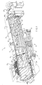
- a rotary lump crusher/reclaimer drum 1 is provided with an outer cylinder 2 and an inner cylinder 3.
- the outer cylinder is provided with an intake compartment 14 wherein lump material, to be processed, is placed into the rotary material crushing drum 1.
- the intake compartment 14 contains helical vanes 20 which are of sufficiently high profile to enable large clumps and lumps of material to be initially separated into smaller lumps of material which are somewhat uniformly distributed on the inner surface of the intake compartment 14.
- the intake compartment 14 which has received material through the intake area 19, the latter of which comprises an opening in the end of the rotary drum 1, conveys the material by the helical vanes 20 forward into the first compartment 15 whereupon the material is further handled by helical vanes or rifling 13.
- the first compartment 15 and the adjacent compartment 16 contain the feeding section with the helical vanes 13 and a crushing and grinding means 23 respectively.
- the crushing and grinding means 23, incorporating serrated shaped means, is anchored in the compartment 16 by a suspension means 29 having chains fastened to the inner wall of the compartment.
- the crushing means 23 is substantially cylindrically shaped, albeit formed as a tapered cylinder having longitudinal ribs 26, that extend along the length of the segments of crusher 24.
- the crushing means 23 is generally a heavy metallic drum-like entity rotatably mounted to a suspension means 29, which functions as a bearing, and which permits the crushing means 23 to rotate by gravity due to the rotation of the cylinders. As rotation occurs, the lump material passes along the first compartment thus entrapping lump material beneath the crusher so as to squash and substantially reduce in size the lump material due to the shape, weight and extensive length of the crushing means 23.
- the crushed material, reduced in size, is passed to the attrition chamber 17.
- the attrition chamber 17 contains apertures 36 in the inner cylinder wall which permit material sufficiently small in size to be classified to pass through the apertures 36.
- the attrition chamber 17 contains blades 33 which assist in further reducing the size of the crushed material received in the attrition chamber 17 from the crushing means 23. The blades lift and drop the granular and lump material. Any material which is not reduced to a size sufficient to pass through the apertures 36, exits through an opening for debris, as at 22, whereby the debris is deposited on an exit chute 25.
- the particulate matter which passes through the apertures 36 is deposited in the space between the outer cylinder 32 and the inner cylinder 33.
- a continuing conveyor means in the form of helical vanes 37 which sweep the material forwardly toward the intake compartment 14.
- the material exits at an exit port 32 onto a screen 35.
- the screen forms the outer portion of the intake compartment.
- Helical vanes 18 are located between the screen 35 and the surface of the intake compartment 14.
- the helical vanes 18 sweep the surface of the screen 35 to direct the particulate matter too large to pass through the screen in the direction of the material pick-up port 34.
- the coarse material is recycled by means of the exit port 34 into the intake compartment 14.
- the material which passes through the screen 35 is deposited in the particulate matter collector 30.
- Located above the intake compartment 14 is a dust collector 21.
- the dust collector does not rotate as part of the rotary media drum nor does the particulate matter collector 30.
- the outer cylinder 2 incorporates upon its external surface, a pair of spaced apart guides, tracks or races as at 4 and 5, which are positioned for riding or sliding upon roller bearings or guides such as can be seen at 6 and 7, the bearings being provided at either side of the apparatus and formed into the base means 8.
- the base means 8 supports the cylinder 2 and the entire apparatus 1 for rotation.
- a drive means such as a motor, as at 9, is provided for cooperating with a sprocket 10 through any suitable inner-connecting gearing means as necessary in order to provide for a controlled rotation of the outer cylinder 2 and its internally arranged components at a controlled speed generally within a range of 1 to 10 rpm.
- the base means 8 is formed of a series of struts as at 11 and generally is designed to be mounted upon shock absorbers such as 12 in order to dampen vibrations and to lessen the noise of operation of the apparatus.
- the outer cylinder 2 extends substantially the entire length of the apparatus with the exception that at the outlet end, as at the chute 25.
- the chute is not in rotation and is designed for stationary mounting.
- an optional mechanism consisting of a burner 27 and a fan 28.
- the burner 27 provides heat which is transmitted by the fan 28 into the exit way 22 and counter to the direction of the movement of the material in the inner cylinder 3. The heat progresses through the material and assists in drying the particulate matter during its separation.
- the outer cylinder 2 and the inner cylinder 3 are affixed to each other so as to rotate simultanteously as the rotation of the rotary lump crusher/reclaimer drum is effected.
- Certain optional modifications may be made to the inner cylinder.
- the inner cylinder in the intake compartment 14, apertures could be placed through its wall so that material small enough to be removed from the process at the beginning, could pass through the wall and to the screen 35.
- the inner cylinder in compartment 15, the inner cylinder could be provided with perforations to allow particulate matter to pass through into the region between the outer cylinder 2 and the inner cylinder 3 whereupon the matter would be transferred, as discussed earlier, onto the classifying screen 35.
- lump material is fed into the intake compartment 14 by a load hopper or vibratory conveyor not shown in the drawing.
- the lumps are regulated against surges because of the larger diameter of the intake compartment than any other portion of the apparatus where the inner cylinder 3 is present.
- the lump material is metered into the crushing compartment 16 by a combination of the high profile segmented helical flights 20 in the intake compartment and the continuous helical vanes or ribs 13 in the first compartment 15.
- the crushing roller 23 provides positive action to reduce large lumps that vary in size and hardness.
- the crushing means 23 is of substantial length and includes a segment having a significant length as at crusher 24 which is generally arranged in contiguity with the bottom surface to the inner cylinder 3 and which may include a series of longitudinal-like ribs 26 so that material fed into this region will be substantially ground by means of the heavy weight of the roller to a much finer size.
- This crushing means revolves by gravity during rotation of the cylinder.
- the entrance end of the crushing means includes a suspension means 29 as can be noted for pivotal rotation within the inner cylinder 3 as a result of the rotation of the inner cylinder 3 during operations of the apparatus.
- the suspension means 29 has an integral bearing to permit the rotation of the roller at a different speed from that of the inner cylinder.
- a suspension means 29 incorporates a housing generally configured in a triangulated or other shape and has linked to it at its apexes a flexible connecting and suspension means such as the shown chains 31.
- the chains 31 are secured by means of connectors to isolated and reinforced parts of the inner cylinder 3 in order to suspend the upper pivotal end of the crushing means 23 approximately centrally but yet flexible in its mounting in the apparatus. In this manner, little interference is provided against movement of the lump material by means of the conveyor vane 13 into the vicinity of the crushing compartment 16.
- the lump material that passes through the lump crushing compartment 16 is reduced by means of the serrated crushing means 23 to a size which generally is then reduced in the attrition chamber to less than the size of the apertures in the attrition chamber 17.
- the crushing section provides a positive action in reducing large lumps to a much smaller size through the action of the crushing ribs 26.
- the ground material is once again forced by the volume of additionally fed material or perhaps through a slight incline in the arrangement of the inner cylinder 3 into the region of the attrition chamber 16 where further particle reducion takes place.
- the inner cylinder 3 is perforated and those particle sizes, generally less than 19 mm (3/4 inch) and smaller, pass into the spacing intermediate, the outer cylinder 2, and the inner cylinder 3 and are moved by means of the continuous vane 37 further longitudinally along the apparatus returning in the direction of the intake compartment.
- That material greater in size than the size of the apertures 36, is lifted by means of the blades 33 and then dropped onto the surface of the inner cylinder for further breakage. If too many of the oversized particles accumulate in the attrition chamber 17, then when the depth is sufficient, the oversized material accumulates and is eventually removed through the debris exit 22 onto the chute for debris 25 which discharges the debris from the apparatus.
- the screening section 35 utilizes punched plate or woven wire screen with openings to meet application specifications.
- the material is classified through a single or multiple screening system that automatically recirculates pieces that are larger than the specifications through the material pick-up exit 34. Apertures are provided through the wall 34a to allow the material to be returned. If desired, when the material is conveyed forward and fails to pass through the screen, it can be directed through a ball mill for further reduction and then returned to the process.
- a dust collection hood 21 encloses the screening section in which a controlled velocity of air removes fines and classifies the material.
- the rotation speed of the rotary lump crusher/reclaimer of the present invention is usually from about 1 to about 10 rpm, preferably from about 4 to about 10 rpm depending on the particular application.
- the drum also can be set up to run on a batch type basis.
- the various sections of the inner cylinder may be fabricated of segmented components, as can be seen in our previous patents, and which are incorporated herein by reference, wherein the segments of the inner cylinder may be formed of a rectangular but arcuate shape, having a segment of a rib 13 integrally formed therewith, and likewise having a segment of a vane 37 formed therewith so that when the sections are fabricated, through their interconnecting together as explained in the prior art, they form the uniform inner cylinder 3 of this rotary lump crusher drum.
- the inner cylinder of the structure may be at least partially formed of liner segments, as explained, such as showing in our previous patents.
Landscapes
- Engineering & Computer Science (AREA)
- Mechanical Engineering (AREA)
- Crushing And Grinding (AREA)
- Processing Of Solid Wastes (AREA)
- Combined Means For Separation Of Solids (AREA)
- Crushing And Pulverization Processes (AREA)
- Molds, Cores, And Manufacturing Methods Thereof (AREA)
Abstract
Description
Claims (5)
- A rotary lump crusher/reclaimer having a drum (1) for reclaiming and reclassifying sand and related aggregates from lump materials, said drum (1) being substantially horizontally disposed for rotation for reclaiming lump materials, and comprising an inner cylinder (3) having an intake area (19) and an exit end (22), said inner cylinder (3) forming an attrition compartment (17) having at least a partially perforated cylinder wall for particulate matter to pass through its perforations (36), an outer cylinder (2) concentric with said inner cylinder (3), a conveying vane (37) provided intermediate the inner and outer cylinder (32) for movement longitudinally of any particular matter deposited therebetween, a screen (35) surrounding the intake area (19), said particulate matter moved by the conveying vane (37) being deposited onto the screen (35) for classification of the particular matter, the matter remaining on the screen (35) being recycled back into the intake area (19), and a base (8) incorporating drive means (9) supporting the drum (1) and driving the drum (1) in rotation,
characterized in that said inner cylinder (3) forms upstream of the attrition compartment (17) a first compartment (15) and a crushing compartment (16), said outer cylinder (2) extending beyond the inner cylinder (3) at the intake area (19) of the inner cylinder (3) to form an intake compartment (14) of larger diameter than the inner cylinder (3) to receive the lump material and having high-profile segmented helical flights (20) to advance the lump material without substantial surges into the first compartment (15) of the inner cylinder (3), said first compartment (15) of the inner cylinder (3) containing means (13) for breaking the lump material into smaller pieces and for advancing the smaller pieces into the crushing compartment (16) where the lump material is crushed into further smaller pieces by means of a lump crusher (23) provided within the crushing compartment (16), crushed material passing from said crushing compartment (16) into said attrition compartment , said attrition compartment (17) having means (33) for subjecting the material to a high tumbling action to further reduce the size thereof, and said exit end (22) having a debris exit (22) being of smaller diameter than the diameter of the inner cylinder (3), any material not passing through the perforations (36) of the attrition compartment (17) leaving the attrition compartment (17) through said debris exit (22). - The rotary lump crusher/reclaimer of claim 1, characterized in that the diameter of the intake compartment (14) is at least ten percent larger than the diameter of the inner cylinder.
- The rotary lump crusher/reclaimer of claim 1, characterized in that the diameter of the intake compartment (14) is approximately the diameter of the outer cylinder (2).
- The rotary lump crusher/reclaimer of claim 1, characterized in that the means (23) for breaking the lump material comprises a lump crusher (23) comprising a length of weighted material forming a crushing means and disposed for partially resting upon the inner surface of the inner cylinder (3), the crushing means being urged into rotation by the turning of the inner cylinder (3) of the rotary reclaiming drum (1), one end of the crushing means being pivotally suspended approximately centrally of the inner cylinder (3), suspension means (29) pivotally holding the one end of the crushing means to the inner cylinder (3), the suspension means (29) including a series of flexible links (31) supporting said one end of the crushing means within the inner cylinder (3).
- The rotary lump crusher/reclaimer of claim 4, characterized in that the flexible links (31) are chains.
Applications Claiming Priority (2)
| Application Number | Priority Date | Filing Date | Title |
|---|---|---|---|
| US08/506,815 US5794865A (en) | 1995-07-25 | 1995-07-25 | Rotary crusher/reclaimer for reclaiming and reclassifying sand and related aggregates from lump materials |
| US506815 | 1995-07-25 |
Publications (2)
| Publication Number | Publication Date |
|---|---|
| EP0755735A1 EP0755735A1 (en) | 1997-01-29 |
| EP0755735B1 true EP0755735B1 (en) | 1999-01-07 |
Family
ID=24016119
Family Applications (1)
| Application Number | Title | Priority Date | Filing Date |
|---|---|---|---|
| EP96630040A Expired - Lifetime EP0755735B1 (en) | 1995-07-25 | 1996-07-25 | Rotary lump crusher/reclaimer for reclaiming and reclassifying sand and related aggregates from lump materials |
Country Status (8)
| Country | Link |
|---|---|
| US (1) | US5794865A (en) |
| EP (1) | EP0755735B1 (en) |
| AT (1) | ATE175368T1 (en) |
| AU (1) | AU698114B2 (en) |
| BR (1) | BR9603185A (en) |
| CA (1) | CA2181976C (en) |
| DE (1) | DE69601289D1 (en) |
| IN (1) | IN189368B (en) |
Cited By (1)
| Publication number | Priority date | Publication date | Assignee | Title |
|---|---|---|---|---|
| CN101974657A (en) * | 2010-10-12 | 2011-02-16 | 株洲冶炼集团股份有限公司 | Device for screening metal smelting scum |
Families Citing this family (27)
| Publication number | Priority date | Publication date | Assignee | Title |
|---|---|---|---|---|
| US6631808B2 (en) | 2001-08-07 | 2003-10-14 | Particle And Coating Technologies, Inc. | Air classifier system for the separation of particles |
| US6691765B2 (en) * | 2001-08-07 | 2004-02-17 | Noram Technology, Ltd. | Products for the manufacture of molds and cores used in metal casting and a method for their manufacture and recycle from crushed rock |
| US7007874B1 (en) * | 2002-01-08 | 2006-03-07 | Leward Nile Smith | Shroud assembly for waste processing machine |
| US7004412B2 (en) * | 2003-11-20 | 2006-02-28 | Carter Day International, Inc. | Micron hammermill |
| NZ532002A (en) * | 2004-03-29 | 2006-11-30 | Rodney Warwick Sharp | Hogger apparatus with inclined drum having screening apertures on side wall, and drum rotating reducing means |
| WO2006093421A1 (en) * | 2005-03-01 | 2006-09-08 | Rodney Warwick Sharp | Improvements in and relating to drums for hogging apparatus |
| US7984866B2 (en) * | 2005-09-23 | 2011-07-26 | Canadian Oil Sands Limited Partnership | Relocatable oil sand slurry preparation system |
| US7775468B2 (en) * | 2007-05-09 | 2010-08-17 | Carter Day International, Inc. | Hammermill with rotatable housing |
| US8544782B2 (en) * | 2007-12-20 | 2013-10-01 | General Kinematics Corporation | Liner for drum and method of assembly |
| US7942354B2 (en) * | 2008-07-29 | 2011-05-17 | Didion Manufacturing Company | Rotary tumbler and metal reclaimer |
| PT2281946E (en) * | 2009-07-09 | 2012-02-15 | Ammann Italy S P A | Rotary drier for plants for the production of bituminous macadams with the use of recycled materials |
| WO2011043907A1 (en) * | 2009-10-08 | 2011-04-14 | Altek, L.L.C. | Process for increasing dross recoveries |
| US20130181077A1 (en) * | 2011-07-19 | 2013-07-18 | Darrell L. Harris | Concentrator Apparatus for Recovering Lead or Other Material |
| WO2013051171A1 (en) * | 2011-10-06 | 2013-04-11 | パナソニック株式会社 | Method for disassembling flat-plate-shaped display device |
| US10668478B2 (en) * | 2013-09-11 | 2020-06-02 | Distron Manufacturing Co. | Multi directional rifling and multi flow variable speed rifling for liner segments for crushers, reclaimers, separators and cleaners for products |
| EP2939745B1 (en) * | 2014-05-02 | 2019-07-10 | Manuel Lindner | Device with impact zone |
| US9370780B2 (en) | 2014-09-17 | 2016-06-21 | Shane T. Nolan | Scrap separation system and device |
| ITUA20164053A1 (en) * | 2016-06-01 | 2017-12-01 | Fonderia Ghirlandina Spa | MIXING PLANT FOR FOUNDRY JETS |
| DK3391969T3 (en) * | 2017-04-18 | 2019-09-02 | Bachofen Willy A Ag | Form-stable ring element for a heat exchanger housing |
| US10399084B2 (en) | 2017-09-29 | 2019-09-03 | Raytheon Company | Media screening devices for capturing media during a deburring process |
| CN107598079A (en) * | 2017-11-06 | 2018-01-19 | 禹州市昆仑模具有限公司 | One kind is new to cover sand calcination room |
| KR102089572B1 (en) | 2018-10-24 | 2020-04-23 | 주식회사 에코비젼21 | Methods of operation of casting processes for the selection and recovery of castings and recovery of iron |
| KR20200097022A (en) | 2019-02-07 | 2020-08-18 | 주식회사 에코비젼21 | Temperature Control Methods and Temperature Control Structure in Liner of Casting Separator |
| KR102173219B1 (en) | 2019-02-07 | 2020-11-03 | 주식회사 에코비젼21 | Velocity Control Methods and Structure in Liner of Casting Separato |
| CN111069527B (en) * | 2019-12-20 | 2021-07-09 | 唐山宏通玛钢有限公司 | Rotor sand mixer for mixing malleable steel casting molding sand |
| US11305293B2 (en) * | 2020-01-08 | 2022-04-19 | Hector DeFino | Method and apparatus for recycling asphalt milings |
| CN113908924B (en) * | 2021-09-18 | 2023-04-07 | 山东大学第二医院 | A traditional chinese medicine capsule granulator for cholelithiasis adjunctie therapy |
Family Cites Families (20)
| Publication number | Priority date | Publication date | Assignee | Title |
|---|---|---|---|---|
| US677691A (en) * | 1900-08-15 | 1901-07-02 | Deering Harvester Company | Apparatus for handling, cleaning, and distributing castings. |
| US788675A (en) * | 1903-01-31 | 1905-05-02 | Ludwig Rissmuller | Apparatus for drying, grinding, and screening. |
| US1736394A (en) * | 1929-04-15 | 1929-11-19 | Arthur H Dierker | Grinding machine |
| US2050458A (en) * | 1932-02-19 | 1936-08-11 | Pioneer Gravei Equipment Mfg C | Apparatus for preparing aggregates |
| GB446966A (en) * | 1934-10-05 | 1936-05-05 | Percy Hutchinson Wilson | Improvements in or relating to the preparation of foundry moulding materials |
| US2523258A (en) * | 1947-06-06 | 1950-09-19 | Ransohoff Inc N | Continuous feed tumbling mill |
| GB807711A (en) * | 1954-05-10 | 1959-01-21 | Smidth & Co As F L | Improvements relating to liners for tube or ball mills |
| DE1220976B (en) * | 1963-05-14 | 1966-07-14 | Kloeckner Humboldt Deutz Ag | Vibrating conveyor for cleaning castings |
| US3554499A (en) * | 1969-03-27 | 1971-01-12 | Royer Foundry & Machine Co | Sand aerating device |
| US3958764A (en) * | 1972-05-17 | 1976-05-25 | The Carborundum Company | Granulating apparatus |
| CH561574A5 (en) * | 1972-06-15 | 1975-05-15 | Mueller Karl A | |
| US3998262A (en) * | 1975-01-06 | 1976-12-21 | Didion Charles J | Casting shake-out unit and method of operation |
| NL7614082A (en) * | 1976-12-17 | 1978-06-20 | Expert Nv | DEVICE FOR COOLING CASTINGS AND TREATING FORM SAND. |
| DE2739148C3 (en) * | 1977-08-31 | 1980-05-22 | Maschinenfabrik Buckau R. Wolf Ag, 4048 Grevenbroich | Rotary drum |
| DE3307323A1 (en) * | 1983-03-02 | 1984-09-06 | F. Kurt Retsch GmbH & Co KG, 5657 Haan | FINE SIZING DEVICE FOR LABORATORY PURPOSES |
| US4674691A (en) * | 1985-10-24 | 1987-06-23 | Didion Manufacturing Company | Dual sand reclaimer |
| US4981581A (en) * | 1989-08-17 | 1991-01-01 | Didion Manufacturing Co. | Dust collection hood for sand reclaimer, cooling, and blending rotary drum |
| US5095968A (en) * | 1990-04-09 | 1992-03-17 | Didion Manufacturing Co. | Rotary media drum with cooling component |
| US5016827A (en) * | 1990-04-09 | 1991-05-21 | Didion Manufacturing Company | Sand reclaiming drum |
| US5267603A (en) * | 1993-01-19 | 1993-12-07 | Didion Manufacturing Company | Sand reclaiming drum with media recycler |
-
1995
- 1995-07-25 US US08/506,815 patent/US5794865A/en not_active Expired - Lifetime
-
1996
- 1996-07-24 AU AU60660/96A patent/AU698114B2/en not_active Ceased
- 1996-07-24 IN IN1338CA1996 patent/IN189368B/en unknown
- 1996-07-24 CA CA002181976A patent/CA2181976C/en not_active Expired - Lifetime
- 1996-07-25 AT AT96630040T patent/ATE175368T1/en not_active IP Right Cessation
- 1996-07-25 BR BR9603185-9A patent/BR9603185A/en not_active IP Right Cessation
- 1996-07-25 DE DE69601289T patent/DE69601289D1/en not_active Expired - Lifetime
- 1996-07-25 EP EP96630040A patent/EP0755735B1/en not_active Expired - Lifetime
Cited By (1)
| Publication number | Priority date | Publication date | Assignee | Title |
|---|---|---|---|---|
| CN101974657A (en) * | 2010-10-12 | 2011-02-16 | 株洲冶炼集团股份有限公司 | Device for screening metal smelting scum |
Also Published As
| Publication number | Publication date |
|---|---|
| AU698114B2 (en) | 1998-10-22 |
| CA2181976A1 (en) | 1997-01-26 |
| BR9603185A (en) | 2003-09-30 |
| IN189368B (en) | 2003-02-15 |
| AU6066096A (en) | 1997-01-30 |
| DE69601289D1 (en) | 1999-02-18 |
| US5794865A (en) | 1998-08-18 |
| ATE175368T1 (en) | 1999-01-15 |
| CA2181976C (en) | 2007-12-04 |
| EP0755735A1 (en) | 1997-01-29 |
Similar Documents
| Publication | Publication Date | Title |
|---|---|---|
| EP0755735B1 (en) | Rotary lump crusher/reclaimer for reclaiming and reclassifying sand and related aggregates from lump materials | |
| US7942354B2 (en) | Rotary tumbler and metal reclaimer | |
| US4728043A (en) | Mechanical sorting system for crude silicon carbide | |
| RU2189865C2 (en) | Method of primary processing of miscellaneous wastes and waste processing plant for realization of this method | |
| JP4601236B2 (en) | Grain sorting system | |
| EP1008405B1 (en) | Molding sand reclaiming apparatus | |
| US3283698A (en) | Refining apparatus | |
| US4050635A (en) | Method and apparatus for reclaiming sand | |
| US3782643A (en) | Apparatus for conditioning a granular material | |
| US3848815A (en) | Granulating apparatus | |
| US3081954A (en) | Method and apparatus for recovering reusable metallics from steel making slag and refuse | |
| US3312403A (en) | Machine and process for reclaiming foundry sand | |
| CA1149580A (en) | Vibrating reclaimer of foundry mold material | |
| JPH09122523A (en) | Tea leaves pulverization processing device | |
| JPH0810633A (en) | Revolution-type impact pulverizing apparatus | |
| JPH07106543B2 (en) | Granular surface polishing equipment | |
| WO2000071257A1 (en) | Reducer and separator for preparing gypsum board and other products for recycling | |
| US3958764A (en) | Granulating apparatus | |
| JP2004114018A (en) | Rough separation device for construction waste, its rough separation line, separation treatment facility and vehicle used for rough separation | |
| CA1168640A (en) | Sand lump crushing device | |
| RU1582447C (en) | Method for regeneration of used molding sands and apparatus for performing the same | |
| CN220969463U (en) | Magnetic separation device for wheat processing | |
| JPH039779A (en) | Abrasive machine for medal | |
| US3768740A (en) | Reclamation of molded sand | |
| JP3024611U (en) | Tea leaf crushing device |
Legal Events
| Date | Code | Title | Description |
|---|---|---|---|
| PUAI | Public reference made under article 153(3) epc to a published international application that has entered the european phase |
Free format text: ORIGINAL CODE: 0009012 |
|
| AK | Designated contracting states |
Kind code of ref document: A1 Designated state(s): AT DE DK FR GB IT |
|
| 17P | Request for examination filed |
Effective date: 19970723 |
|
| 17Q | First examination report despatched |
Effective date: 19970909 |
|
| GRAG | Despatch of communication of intention to grant |
Free format text: ORIGINAL CODE: EPIDOS AGRA |
|
| GRAG | Despatch of communication of intention to grant |
Free format text: ORIGINAL CODE: EPIDOS AGRA |
|
| GRAH | Despatch of communication of intention to grant a patent |
Free format text: ORIGINAL CODE: EPIDOS IGRA |
|
| GRAH | Despatch of communication of intention to grant a patent |
Free format text: ORIGINAL CODE: EPIDOS IGRA |
|
| GRAA | (expected) grant |
Free format text: ORIGINAL CODE: 0009210 |
|
| AK | Designated contracting states |
Kind code of ref document: B1 Designated state(s): AT DE DK FR GB IT |
|
| PG25 | Lapsed in a contracting state [announced via postgrant information from national office to epo] |
Ref country code: FR Free format text: LAPSE BECAUSE OF FAILURE TO SUBMIT A TRANSLATION OF THE DESCRIPTION OR TO PAY THE FEE WITHIN THE PRESCRIBED TIME-LIMIT Effective date: 19990107 Ref country code: AT Free format text: LAPSE BECAUSE OF FAILURE TO SUBMIT A TRANSLATION OF THE DESCRIPTION OR TO PAY THE FEE WITHIN THE PRESCRIBED TIME-LIMIT Effective date: 19990107 |
|
| REF | Corresponds to: |
Ref document number: 175368 Country of ref document: AT Date of ref document: 19990115 Kind code of ref document: T |
|
| REF | Corresponds to: |
Ref document number: 69601289 Country of ref document: DE Date of ref document: 19990218 |
|
| ITF | It: translation for a ep patent filed |
Owner name: UFFICIO BREVETTI RICCARDI & C. |
|
| PG25 | Lapsed in a contracting state [announced via postgrant information from national office to epo] |
Ref country code: DK Free format text: LAPSE BECAUSE OF FAILURE TO SUBMIT A TRANSLATION OF THE DESCRIPTION OR TO PAY THE FEE WITHIN THE PRESCRIBED TIME-LIMIT Effective date: 19990407 |
|
| PG25 | Lapsed in a contracting state [announced via postgrant information from national office to epo] |
Ref country code: DE Free format text: LAPSE BECAUSE OF FAILURE TO SUBMIT A TRANSLATION OF THE DESCRIPTION OR TO PAY THE FEE WITHIN THE PRESCRIBED TIME-LIMIT Effective date: 19990408 |
|
| EN | Fr: translation not filed | ||
| PLBE | No opposition filed within time limit |
Free format text: ORIGINAL CODE: 0009261 |
|
| STAA | Information on the status of an ep patent application or granted ep patent |
Free format text: STATUS: NO OPPOSITION FILED WITHIN TIME LIMIT |
|
| 26N | No opposition filed | ||
| REG | Reference to a national code |
Ref country code: GB Ref legal event code: IF02 |
|
| PGFP | Annual fee paid to national office [announced via postgrant information from national office to epo] |
Ref country code: GB Payment date: 20150721 Year of fee payment: 20 |
|
| PGFP | Annual fee paid to national office [announced via postgrant information from national office to epo] |
Ref country code: IT Payment date: 20150727 Year of fee payment: 20 |
|
| REG | Reference to a national code |
Ref country code: GB Ref legal event code: PE20 Expiry date: 20160724 |
|
| PG25 | Lapsed in a contracting state [announced via postgrant information from national office to epo] |
Ref country code: GB Free format text: LAPSE BECAUSE OF EXPIRATION OF PROTECTION Effective date: 20160724 |