EP0754945B1 - A method and apparatus for determining the erythrocyte sedimentation rate - Google Patents
A method and apparatus for determining the erythrocyte sedimentation rate Download PDFInfo
- Publication number
- EP0754945B1 EP0754945B1 EP95111491A EP95111491A EP0754945B1 EP 0754945 B1 EP0754945 B1 EP 0754945B1 EP 95111491 A EP95111491 A EP 95111491A EP 95111491 A EP95111491 A EP 95111491A EP 0754945 B1 EP0754945 B1 EP 0754945B1
- Authority
- EP
- European Patent Office
- Prior art keywords
- blood
- cell
- interval
- reading
- column
- Prior art date
- Legal status (The legal status is an assumption and is not a legal conclusion. Google has not performed a legal analysis and makes no representation as to the accuracy of the status listed.)
- Expired - Lifetime
Links
Images


Classifications
-
- G—PHYSICS
- G01—MEASURING; TESTING
- G01N—INVESTIGATING OR ANALYSING MATERIALS BY DETERMINING THEIR CHEMICAL OR PHYSICAL PROPERTIES
- G01N15/00—Investigating characteristics of particles; Investigating permeability, pore-volume, or surface-area of porous materials
- G01N15/04—Investigating sedimentation of particle suspensions
- G01N15/05—Investigating sedimentation of particle suspensions in blood
Definitions
- the present invention relates generally to determining the erythrocyte sedimentation rate (ESR) in a blood sample.
- ESR erythrocyte sedimentation rate
- the standard laboratory method heretofore used for measuring ESR is the so-called Westergren method.
- Westergren method A general review of that method is provided in "ICSH recommendations for measurement of erythrocyte sedimentation rate" published in Journal of Clinical Pathology 1993; 46: 198-203.
- the Westergren method provides for a sample of blood to be collected in a test tube (pipette) to form a 200 mm blood column in the presence of an anticoagulant.
- a test tube pipette
- the test tube is loaded into a device or an instrument including sensors such as an optical sensor to record the location of the blood/air meniscus at an initial time.
- the operator or the sensor identifies and measures the location of the cell/plasma interface. The distance in millimetres from initial blood/air meniscus and the final cell/plasma interface gives the typical Westergren output value for the test which is expressed in units of mm/hr.
- a basic disadvantage of the conventional Westergren method lies in the considerable length of the test tube (typically in excess of 200 mm) which makes it unsuitable for use in collecting blood directly. Consequently, blood for the test has to be taken either by using a syringe or a pre-evacuated tube and the blood thus collected must then be transferred to the Westergren test tube. In addition to being unpractical, such a procedure exposes the operator to the danger of contacting the blood during the transfer process.
- Exemplary of such prior art are, for instance, the arrangement disclosed in FR-A-2 394 797, where reference is made to possible use of test tubes having lengths in the 100 mm - 200 mm. range, or the ESR measuring system sold under the trademark SEDISCAN by the assignee of the present application. This system and the respective method of operation were taken as a basis for the preambles of Claims 1 and 21.
- a SEDISCAN instrument is adapted for use in connection with tubes (sold under the trademark SEDITAINER - both SEDISCAN and SEDITAINER being registered trademarks of Becton Dickinson and Company) essentially comprised of 5 ml draw tube of 120 mm length and 10.25 mm outer diameter containing liquid sodium citrate/citric acid at 4:1 ratio.
- the SEDISCAN instrument provides an extrapolated Westergren value after 30 minutes which compares well to actual 60 and 120 minutes Westergren values.
- test tube for proper use in ESR measuring test to carry patient identification data which must not and cannot be removed at any time, while carrying out the test.
- the basic underlying problem of the present invention is providing a solution which jointly overcomes the drawbacks of the prior art solutions, i.e. by providing an ESR determination procedure, where:
- a pre-evacuated test tube is used to collect the specimen which is made of such a material as glass or plastics and which contains an anticoagulant.
- the tube is then put into a rack and loaded into an instrument which mixes the specimen briefly.
- the instrument uses optical sensors to record the location of the blood/air meniscus at an initial time. At subsequent time intervals thereafter for periods up to 30 minutes, typically 20 minutes or less, the optical sensors then identify and measure the location of the cell/plasma interface. These measured values are then converted by a given relationship, e.g. an algorithm, to the values which would be obtained using the classical Westergren method (200 mm blood column height and blood to citrate ratio of 4:1).
- an exemplary tube according to the invention is generally designated T.
- the tube T which may be typically constructed from glass or plastic, has a tubular, preferably cylindrical wall with an outside diameter of not less than about 7 mm and not more than about 9 mm.
- the length of the tube T (which roughly corresponds to the height of the blood column formed therein) is preferably not less than about 75 mm, but not more than about 105 mm and still preferably about 80 mm.
- the inside diameter is preferably not less than about 5 mm and not more than about 7 mm and still preferably about 6 mm.
- tube is not to be construed as strictly limited to the typical test tube (pipette) arrangement exemplified in fig.1. Even though the one shown is held at present to constitute the best mode of carrying out the invention, alternative arrangements can be devised, such as one where the tube is incorporated to an instrument or device adapted for collecting blood and then conveying it (e.g. by means of a pumping action) to a tubular member adapted for forming the blood column which is used for carrying out the test.
- the inner diameter of the tube T must be sufficiently large to allow the blood specimen used for the test to mix adequately immediately after collecting to ensure complete anticoagulation is achieved. Subsequently, immediately before initiating the measurement of the ESR, the specimen must be uniformly and completely mixed to re-suspend blood cells.
- An inner diameter below about 5 mm slows mixing to such a degree that clotting and cell aggregation occur subsequently, causing an unpredictable acceleration of the rate of cell falling during the ESR measurement and thus error in the correlation with the classical Westergren method.
- the inner diameter and tube length should also be sufficiently small to minimise the volume of the blood required from the patient for the test, since excessive blood lost by patients is considered detrimental to their health. This is particularly the case for paediatric patients who have small blood volumes and geriatric patients who have diminished capacity to regenerate blood cells. In the configuration described, blood requirements would be typically less than 2 mls which is considered sufficiently small to have little impact on patient health.
- the outer diameter and tube wall thickness must be sufficiently large to add sufficient strength and rigidity to ensure the tube does not break or bend during handling and subsequent testing. However, they should be sufficiently small to ensure the tube is easy to cut, form and glaze as in the case of a glass tube or injection moulded as in the case of a plastics tube. Excess material leads to higher manufacturing cost and an overly thick tube wall could reduce the ability of an optical viewing device to see through the wall when attempting to identifying the meniscus and the interface.
- Optical imaging devices such as a LCDs, linear CCDs and video cameras, are preferably used in connection with a visibly transparent tube wall (at least insofar as the "window" of the tube actually observed is concerned), e.g. made of glass or transparent plastics.
- a visibly transparent tube wall at least insofar as the "window" of the tube actually observed is concerned
- non-optical sensors and/or visibly opaque, non-transparent tube walls are used.
- Exemplary of such alternative embodiments are imaging devices operating outside the visible range (e.g. infrared radiation) or devices operating with other kinds of radiation or based on other physical phenomena (e.g. capacitive sensors and the like).
- Optical devices are however preferred due to the current availability of devices adapted for use within the framework of the invention.
- Exemplary of such devices are, in addition to the one used in the assignee's SEDISCAN R system, those sold under the trade names Sony CCB-M25/CE (CCD) and Sony PSB9151A (power board) [Sony, Kanafawa, Japan] and Computak 6mm 1:1-2 1/2 C (Lens from Japan).
- the open end of the tube T is preferably sealed by a stopper S having vacuum and moisture barrier properties suitable to maintain the additive contents and blood drawing capability for periods in excess of two weeks and preferably for periods in excess of one year.
- the stopper S is preferably an elastomeric material such as bromobutyl or chlorobutyl rubber which is also easy to penetrate using a double-ended blood collection needle and which re-seals upon needle removal to prevent leakage of the specimen.
- the external diameter of the stopper S is preferably between about 12 and about 17 mm, such that it can be easily inserted into, centered on the needle and removed from a standard needle holder. Exemplary of such a stopper are the stoppers found on evacuated blood collection tubes and sold by the assignee company under the trademarks VACUTAINER®, HEMOGARD® and PLUS®.
- the tube T according to the invention may be packaged and sold as a stand-alone, disposable, product comprised of the tube body proper (made of glass or plastics, for instance) pre-evacuated and sealed by the stopper S and also including a quantity of additive A.
- the additive is intended to act as an anticoagulating agent/mixing aid.
- the additive is a mixture of tri-sodium citrate (Na 3 ) and citric acid mixed in an aqueous solution to achieve a molarity of 0.105 M-0.135 M.
- Sufficient solution e.g. 0.46 cc - referring to the preferred dimensions of the tube T referred to in the foregoing
- blood to additive ratio starting at about 2:1 and below and up to about 10:1 and above are possible; the mathematical algorithm which converts the observed rate of cell settling to the classical Westergren value is adapted accordingly.
- anticoagulants such as EDTA, Hirudin and its analogues or potassium and sodium oxalate can be used in a variety of forms, such as liquid, freeze dried, powder or spray coatings. Each may be equally effective in anticoagulating the specimen without haemolysis and with an appropriate mathematical algorithm will allow conversion of the observed value to the Westergren value.
- Non-liquid, e.g. dry additives are usually preferred in the case of plastics tubes due to the well-known tendency of plastic tube to lose moisture.
- a component which reduces the surface tension of the blood is preferably added to the tube as a coating or combined with the anticoagulant in its liquid or dry form.
- the surfactant is a nonionic surfactant.
- An example of such a surfactant is an organosilicone.
- the organosilicone is a polyalkyleneoxide modified polydimethyl-siloxane. Polyalkyleneoxide modified polydimethyl siloxanes are found to be stable with irradiation, do not cause the blood to haemolysis and increases the rate of mixing the specimen to provide a well anticoagulated and homogeneous specimen without cell aggregation or clotting.
- Fig.2 and 3 show a rack 1 adapted for receiving one or, preferably, a plurality of tubes T, a light source 2, such as a fluorescence light arranged on one side of the rack 1 to create background illumination, as well as an optical imaging device such as a video camera 3, arranged on the other side of the rack 1 and adapted for viewing, as better described in the following, the tube or the tubes T against the background illumination created by the source 2.
- a light source 2 such as a fluorescence light arranged on one side of the rack 1 to create background illumination
- an optical imaging device such as a video camera 3
- the location of the cell/plasma interface (schematically designated I in fig.2) is thus detected as a contrasted image (dark/clear, black/white) against said background illumination.
- the rack 1 is essentially comprised of a C-shaped frame having opposite lower 4 and upper 5 arms adapted for securely receiving the lower and upper ends of the tube or tubes T.
- the two horizontal arms 4, 5 are connected by an upright arm 6 which is rigidly fixed to one of the arms (for instance upper arm 5) and is hinged at 7 to the other (in the present instance lower) arm 4.
- This arrangement permits the rack 1 to be opened to insert the or each tube T into respective cavities 8 provided in the lower arm 4 and then securely locked to their final position for carrying out the test by bringing the rack 1 to its closed position with the upper arm 5 (having respective cavities or a cutout on the lower side thereof - not visible in the drawing) to engage the upper ends of the tube or tubes T (closed by the stopper S).
- the rack 1 is then locked to its closed position by means of a lock mechanism controlled by a thumb-actuated slider 9.
- the camera 3 has associated therewith drive means (such as a motor-driven toothed belt 3a) which cause it to undergo a traverse movement (as shown by the double-pointed arrow of fig. 3) along the tube or tubes T.
- the motor moves the camera to view each rack (three such racks are provided in a linear array in the currently preferred embodiment of the invention).
- the motor does not move the camera during the period when the camera is viewing a specific rack.
- the camera sees a 2-dimensional picture of the rack and thus can see the entire aspect of each tube in a rack. After reading one rack, the camera is moved by the motor to view the next rack.
- a rotary mounting fixture including a rotary platform or drum carrying supporting formations which enable the rack 1 to be safely retained on the mounting fixture as this is rotated about a horizontal axis XR under the action of motor means (not shown).
- the rack 1 and the tube or tubes T located therein are vertically rotated about an axis XR to achieve thorough mixing of the specimen immediately before initiating the optical reading.
- the rack 1 also allows the tube or tubes T to be optically observed from the side starting immediately above the blood/ air meniscus and continuing downward over a distance defining a window W as explained in detail in the following.
- the rack arrangement described in the foregoing is not - per se - critical to the invention.
- Other arrangements such as the one currently used in the SEDISCAN R system, can be used. This also applies to the nature of the imaging device embodied by the video camera 3.
- LCDs linear CCD arrays and other devices (including non-optical devices) may be used.
- the arrangement for causing the camera 3 to move along the rack array, as well as the rotary mounting fixture for the racks 1, are conventional in the art and do not require to be described in further detail.
- the foregoing also applies - in general terms - to the computer-controlled arrangement adopted for processing the output signal from the camera 3 and the possibility of using a manual scanner 10 for identifying each and every tube T as it is loaded into the respective rack 1.
- the manual scanner 10 enables each patient's identification data (usually in the form of a bar code) to be read from a label L applied around the lower portion of each tube T when collecting the blood samples.
- Both the output signal (which is usually converted to a digital format) as well the signal from the manual scanner 10 are fed to a data processing unit, such as a personal computer 11.
- a dedicated computer or processor can be used as an alternative to a programmed general purpose computers.
- Suitable programming (according to well-known criteria which are not required to be described here) enables each tube T to be safely identified as such, prior to loading into the instrument, while the respective camera reading 3, converted to a standard Westergren value, can be outputted as a visual display on a screen and/or a hard copy printout or communicated electronically to the host computer managing patient data in the laboratory.
- the host computer managing patient data in the laboratory.
- tubes T When a plurality of tubes (such as fifteen tubes) T are tested simultaneously in a rack, these are preferably arranged in the rack in an array including two parallel rows, as shown in fig.2, with the tubes T in the adjacent rows suitably staggered or offset in order to make sure that all the tubes T in the two-row array can be inspected by the camera 3 moving along a line parallel to the two rows.
- the locations of the tubes in each rack 1 are such that all the tubes in the rack can be inspected simultaneously by the camera 3 positioned at a given point with respect of the rack 1. That point is preferably chosen to correspond to a central positioning of the camera 3 with respect to the length of the rack.
- each rack 1 can be viewed simultaneously by the camera 3 from a single location, the camera 3 needs to be stopped only once for each rack, without any scanning movement being required.
- three racks are arranged to be tested simultaneously, and the movement of the camera 3 along the guide 3a is thus stopped three times. Suitable controls may however be provided in order to prevent the camera from stopping at any location where, for any reasons, no rack, a rack containing no tubes or a rack containing only empty tubes are arranged.
- the tubes T are held inclined at an angle ⁇ with respect to the vertical.
- this result can be easily achieved simply by stopping the rotary motion of the mounting fixture carrying the rack 1 at the end of the mixing stage at a position which leaves the tube(s) T oriented approximately 20° from the vertical position.
- reference indicia (such as a notch or an optical mark 12) can be provided on the rotary fixture carrying the racks 1.
- Such indicia are detected by respective sensors 12a (of known type), acting as angular position sensing means, in order to stop the rotary motion of the fixture at the desired angular position.
- a short blood collection tube (about 80 mm to about 110 mm, about 80 mm being the presently preferred value) whereby a blood column may be formed therein having a height of not less than about 75 mm and not more than about 105 mm.
- the tube is preferably inclined at approximately 20° to accelerate the rate at which the cells fall, making it possible to read significant displacements in the cell/plasma interface sooner than 60 minutes (preferably about 20 minutes or less).
- the optical viewing device is sized or adjusted only to read a short length (30-40 mm or less contrary to 70-80 mm of the SEDISCAN R system) of the tube T located at the top thereof, "at the top” meaning a length or window W which encompasses the blood/air meniscus in the tube T upon starting the test or has its upper margin lower than the blood air/meniscus and located in proximity thereto.
- the invention provides a solution for giving thoroughly reliable results to the patient in a much faster period than in the past.
- the solution of the invention provides for cell falling being monitored only over a reduced length or window of the blood column in the tube while providing thoroughly reliable results even if the overall period the cell falling phenomenon is observed is reduced to 20 minutes or less.
- the window W is only a portion of the entire tube length (see especially fig.1) the remaining tube length can be used to apply patient identification labels L to ensure the diagnostic result is properly matched by the laboratorian to the correct patient.
- This is particularly important as the use of bar code style positive patient identification labels L adapted for reading by manual scanners, such as scanner 10, has increased rapidly in an effort by hospitals to improve quality of care while increasing laboratory efficiency and throughput.
- These labels L are typically a 30-50 mm long (in the axial direction of the tube T).
- the present invention provides the significant advantage of being able to apply typical labels L onto the exterior of a primary tube for an ESR determination in an area (the lower portion of the tube T shown in fig.1) which does not obstruct the measurement.
- This is essentially due to the fact that - according to the invention - only a minor portion ("minor” meaning about 50% or less, typically about 30% or less) of the blood column within the tube T is actually used for determination.
- the remaining lower portion of the blood column while playing a role in the overall cell falling phenomena, can be covered by the label L as it will not be used for determination purposes.
- the sedimentation rate expressed in mm/hr for the Westergren reference method was collected using the standard glass pipette at the specified time intervals of 60 and 120 minutes alter initiation of the test.
- the initial blood meniscus height in the tube at time 0 was determined.
- the location of the cell/plasma interface was observed via the camera system and measured by the instrument. This data was collected at intervals of about 10, 15 and 20 minutes after the initial time.
- this data was first analyzed graphically by plotting the observed value at each time interval versus the reference method value and determining the correlation.
- the reading intervals can be chosen to be more frequent or less frequent than the 10,15 and 20 minute intervals described here. Consequently, the preferred coefficients disclosed in Tables 1 and 2 may vary accordingly.
- the system described here provides predictions after 20 minutes for the Westergren value classically obtained using the reference method alter 60 and 120 minutes.
- the new system clearly offers significant advantage to the user by providing diagnostic values faster to the clinicians. By shortening the reading cycle further through the development of alternative algorithms in the manner described herein or in similar manners, it would further add advantage for the clinician.
- Such factors may include the patient haematocrit as it is well established that decreasing haematocrit can accelerate the sedimentation rate.
Description
- "short" tubes are used, preferably adapted for direct blood collection;
- patient identification data, once applied onto the tube, cannot be removed from it, thereby making it impossible to dis-associate the specimen from the patient identification;
- reliable ESR values are provided in a term much shorter then the standard 60 or 120 minutes of the Westergren; and
- the quantity of blood to be taken from the patient is minimised.
- fig.1 shows a test tube according to the invention,
- figs.2 and 3 show diagrammatically the typical arrangement of device of the invention, and
- figs.4 to 7 show the correlation between the results of the method of the invention and the results which would be obtained using the classical Westergren method.

Claims (31)
- A method for determining the erythrocyte sedimentation rate (ESR) in a blood sample, including the steps of:forming a column of said blood, said blood column having a given height at an initial time; andmeasuring at at least one subsequent time interval the location of the cell/plasma interface (I) with respect to the height of said blood column, said location being indicative of the ESR of the said blood sample,
characterised in that it includes the step of measuring the location of said interface over a length (W) being about 50% or less, and typically about 30% or less of the height of said blood column by measuring the location of said cell/plasma interface (I) at at least one first and at least one second intervals of less than 30 minutes from said initial time and in that said ESR is determined as a standard Westergren value for ESR computed by polynomial interpolation starting from the locations measured at said at least first and said at least second time intervals. - The method of claim 1, characterised in that said length (W) is located at the top of said blood column.
- The method of either of claims 1 or 2, characterised in that said blood column has a height of not less than about 75 mm and not more than about 105 mm.
- The method of any of claims 1 to 3, characterised in that said blood column has a height of about 80 mm.
- The method of any of claims 1 to 4, characterised in that said blood column has a diameter of not less than about 5 mm and not more than about 7 mm.
- The method of claim 5, characterised in that said blood column has a diameter of about 6 mm.
- The method of any of claims 1 to 6, characterised in that said length (W) is about 30-40 mm.
- The method of any of the preceding claims, characterised in that it includes the step of mixing the blood forming said column before said initial time.
- The method of claim 8, characterised in that mixing is effected by vertical rotation (XR) of said blood column.
- The method of any of the preceding claims, characterised in that said blood column is inclined with respect to the vertical position.
- The method of claim 10, characterised in that said blood column is kept at an angle of about 20° with respect to the vertical position.
- The method of claims 9 and 10, characterised in that said vertical rotation is stopped at a position where said blood column is inclined with respect to the vertical position.
- The method of any of the preceding claims, characterised in that it includes the step of detecting the location of said cell/plasma interface (I) by optical detecting means (3).
- The method of claim 13, characterised in that it includes the step of providing background illumination (2) for said blood column and detecting the location of said cell/plasma interface (I) as a contrasted image against said background illumination (2).
- The method of claim 1 characterised in that it includes the steps of measuring the location of said cell/ plasma interface (I) at a time interval of up to 20 minutes from said initial time.
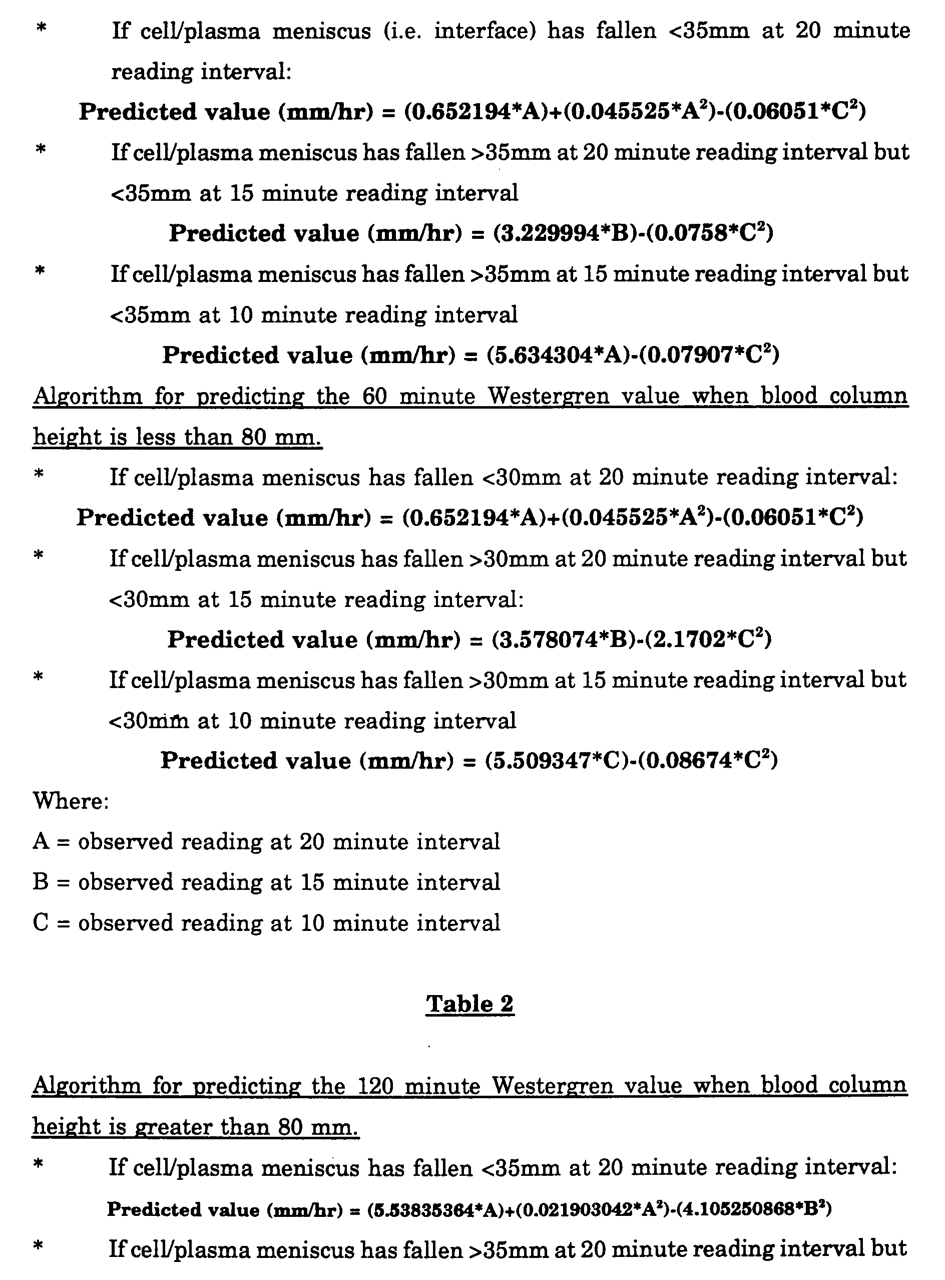
- The method of claim 1, characterized in that said standard Westergren value is computed as a predicted 60 minute Westergren value as follows:Where:a) if the height of said blood column is greater than about 80 mm.If cell/plasma meniscus interface has fallen about <35mm at a first reading interval:
 If cell/plasma interface has fallen > about 35mm at said first reading interval but < about 35mm at a second reading interval
 If cell/plasma interface has fallen > about 35mm at a said second reading interval but < about 35mm at a third reading interval
 b) if the height of said blood column height is less than about 80 mm.If cell/plasma interface has fallen < about 30mm at said first reading interval:
 If cell/plasma interface has fallen > about 30mm at said first reading interval but < about 30mm at said second reading interval:
 If cell/plasma interface has fallen > about 30mm at said second reading interval but < about 30mm at said third reading interval
 A = observed reading at said first intervalB = observed reading at said second intervalC = observed reading at said third intervala1-a11 are constant values.
 - The method of claim 16, characterized in that said constant values (a1-a11) are as follows:a1 = 0.652194a2 = 0.045525a3 = 0.06051a4 = 3.229994a5 = 0.0758a6 = 5.634304a7 = 0.07907a8 = 3.578074a9 = 2.1702a10 = 5.509347a11 = 0.08674
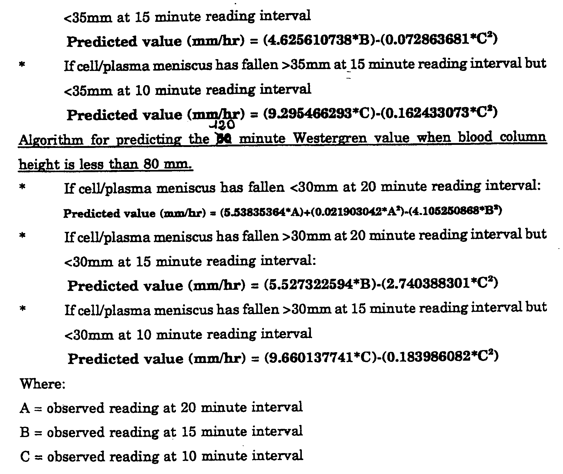
- The method of claim 1, characterized in that said standard Westergren value is computed as a predicted 120 minute Westergren value as follows:Where:a) if the height of said blood column height is greater than about 80 mmIf cell/plasma interface has fallen < about 35mm at a first reading interval:
 If cell/plasma interface has fallen > about 35mm at said first reading interval but < about 35mm at a second reading interval
 if cell/plasma interface has fallen > about 35mm at said second reading interval but < about 35mm at a third reading interval
 b) if the height of said blood column is less than about 80 mm.If cell/plasma interface has fallen < about 30mm at said first reading interval:
 If cell/plasma interface has fallen > about 30mm at said first reading interval but < about 30mm at said second reading interval:
 If cell/plasma interface has fallen > about 30mm at said second reading interval but < about 30mm at said third reading interval
 A = observed reading at said first intervalB = observed reading at said-second intervalC = observed reading at said third intervalb1-b11 are constant values.
 - The method of claim 18, characterized in that said constant values (b1-b11) are as follows:b1 = 5.53835364b2 = 0.021903042b3 = 4.105250868b4 = 4.625610738b5 = 0.072863681b6 = 9.295466293b7 = 0.162433073b8 = 5.527322594b9 = 2.740388301b10 = 9.660137741b11 = 0.183986082
- The method of any claims 16 to 19, characterized in that said first, second and third reading intervals are equal to about 20, 15 and 10 minutes respectively.
- Apparatus for determining the erythrocyte sedimentation rate (ESR) in a blood sample, said apparatus including:test tube means (T) for forming in use a column of said blood, said blood column having a given height at an initial time; anddetector means (3) for measuring at at least one subsequent time interval the location of the cell/plasma interface (I) with respect to the height of said blood column in said test tube means (T), said location being indicative of the ESR of the said blood sample,
characterised in that:said detector means (3) measure the location of said interface over a length (W) being about 50% or less, and typically about 30% or less of the height of said blood column in said test tube means (T) to generate at least one signal indicative of said location, andprocessor means (11) are associated with said detector means (3) said processor means (11) measuring from said at least one signal the location of said cell/plasma interface (I) at at least one first and at least one second intervals of less than 30 minutes, and preferably up to 20 minutes, from said initial time and determine said value representative of the ESR as a standard Westergren value for ESR computed by polynomial interpolation starting from the locations measured at said at least first and said at least second time intervals. - The apparatus of claim 21, characterised in that said detector means (3) measure the location of said interface over a length (W) located at the top of said blood column in said test tube means (T), and in that said test tube means (T) includes a tubular wall adapted for forming a blood column having a length of not less than about 75 mm and not more than about 105 mm said tubular wall having an inside diameter not less than about 5 mm and not more than about 7 mm.
- The apparatus of claim 22, characterised in that said test tube means (T) includes a tubular wall adapted for forming a blood column having a length of about 80 mm and a diameter of about 6 mm.
- The apparatus of any of claims 22 or 23, characterised in that said tubular wall has an outside diameter of not less than about 7 mm and not more than about 9 mm.
- The apparatus of claim 24, characterised in that said tubular wall has an outside diameter of about 8 mm.
- The apparatus of any of claims 21 to 25, characterised in that said length (W) is about 30-40 mm.
- The apparatus of any of claims 21 to 26, characterised in that said test tube means (T) have associated therewith a rotary mounting fixture for mixing the blood forming said column in said test tube means (T) before said initial time.
- The apparatus of claim 27, characterised in that said rotary mounting fixture is arranged for vertical rotation (XR) of said test tube means (T).
- The apparatus of claim 28, characterised in that rotary mounting fixture has associated therewith angular position sensing means (12, 12a) for stopping said rotary mounting fixture at a position (12) where said blood column in said test tube means (T) is inclined with respect to the vertical position.
- The apparatus of any of claims 21 to 29 characterised in that said detector means (3) are optical detecting means (3).
- The apparatus of claim 30, characterised in that it includes a background illumination source (2) for said tube means (T), whereby said optical detecting means (3) detect the location of said cell/plasma interface (1) as a contrasted image against the background illumination of said source (2).
Priority Applications (6)
| Application Number | Priority Date | Filing Date | Title |
|---|---|---|---|
| ES95111491T ES2151939T3 (en) | 1995-07-21 | 1995-07-21 | METHOD AND APPLIANCE TO DETERMINE THE RATE OF SEDIMENTATION OF Erythrocytes. |
| DE69518834T DE69518834T2 (en) | 1995-07-21 | 1995-07-21 | Method and device for determining the erythrocyte sedimentation rate |
| EP95111491A EP0754945B1 (en) | 1995-07-21 | 1995-07-21 | A method and apparatus for determining the erythrocyte sedimentation rate |
| US08/670,475 US5745227A (en) | 1995-07-21 | 1996-06-26 | Method and apparatus for determining the erythrocyte sedimentation rate |
| CA002181634A CA2181634C (en) | 1995-07-21 | 1996-07-19 | A method and apparatus for determining the erythrocyte sedimentation rate |
| JP8192568A JPH09101303A (en) | 1995-07-21 | 1996-07-22 | Erythrocyte-sedimentation-velocity measuring method |
Applications Claiming Priority (1)
| Application Number | Priority Date | Filing Date | Title |
|---|---|---|---|
| EP95111491A EP0754945B1 (en) | 1995-07-21 | 1995-07-21 | A method and apparatus for determining the erythrocyte sedimentation rate |
Publications (2)
| Publication Number | Publication Date |
|---|---|
| EP0754945A1 EP0754945A1 (en) | 1997-01-22 |
| EP0754945B1 true EP0754945B1 (en) | 2000-09-13 |
Family
ID=8219453
Family Applications (1)
| Application Number | Title | Priority Date | Filing Date |
|---|---|---|---|
| EP95111491A Expired - Lifetime EP0754945B1 (en) | 1995-07-21 | 1995-07-21 | A method and apparatus for determining the erythrocyte sedimentation rate |
Country Status (6)
| Country | Link |
|---|---|
| US (1) | US5745227A (en) |
| EP (1) | EP0754945B1 (en) |
| JP (1) | JPH09101303A (en) |
| CA (1) | CA2181634C (en) |
| DE (1) | DE69518834T2 (en) |
| ES (1) | ES2151939T3 (en) |
Cited By (7)
| Publication number | Priority date | Publication date | Assignee | Title |
|---|---|---|---|---|
| US8107715B2 (en) | 2006-05-15 | 2012-01-31 | Sartorius Stedim Biotech Gmbh | Method and detection device for the imaging detection of a sample |
| RU2640190C2 (en) * | 2016-05-04 | 2017-12-26 | Федеральное государственное бюджетное образовательное учреждение высшего образования "Тамбовский государственный технический университет" ФГБОУ ВО ТГТУ | Method for determining change dynamics of erythrocyte sedimentation rate |
| RU2655523C2 (en) * | 2016-10-24 | 2018-05-28 | Федеральное государственное бюджетное образовательное учреждение высшего образования "Тамбовский государственный технический университет" (ФГБОУ ВО "ТГТУ") | Method for determining dynamics of measuring erythrocyte sedimentation rate |
| RU2660710C1 (en) * | 2017-06-27 | 2018-07-09 | Федеральное государственное бюджетное образовательное учреждение высшего образования "Тамбовский государственный технический университет" (ФГБОУ ВО "ТГТУ") | Method for determining the dynamics of the change in the rate of erythrocyte sedimentation |
| RU2695072C1 (en) * | 2018-03-06 | 2019-07-19 | Федеральное государственное бюджетное образовательное учреждение высшего образования "Тамбовский государственный технический университет" (ФГБОУ ВО "ТГТУ") | Method for determining changes in erythrocyte sedimentation rate |
| WO2024002939A1 (en) * | 2022-06-28 | 2024-01-04 | Diesse Diagnostica Senese S.P.A. | System for the carrying out analyses of blood samples with improved optoelectronic systems |
| WO2024002870A1 (en) * | 2022-06-28 | 2024-01-04 | Diesse Diagnostica Senese S.P.A. | Improved system for the measurement of the erythrocyte sedimentation rate and related method |
Families Citing this family (26)
| Publication number | Priority date | Publication date | Assignee | Title |
|---|---|---|---|---|
| US6534016B1 (en) | 1997-04-30 | 2003-03-18 | Richmond Cohen | Additive preparation and method of use thereof |
| US6225123B1 (en) * | 1997-04-30 | 2001-05-01 | Becton Dickinson And Company | Additive preparation and method of use thereof |
| USD432245S (en) * | 1999-07-27 | 2000-10-17 | Becton Dickinson And Company | Collection assembly with a specimen label |
| WO2001023864A1 (en) * | 1999-09-27 | 2001-04-05 | Adelio Missaglia | Apparatus for testing blood samples |
| JP2001245874A (en) * | 2000-03-03 | 2001-09-11 | Sefa Technology Kk | Blood collecting tube for measuring red corpuscle sedimentation speed, blood collecting tube holder, protector for carrying blood collecting tube, and method and device for measuring red corpuscle sedimentation speed |
| US6691057B2 (en) * | 2001-02-26 | 2004-02-10 | L.U.M. Gesellschaft Fur Labor- Umweltdiagnostic & Medizintechnik Mbh | Method and device for accelerated stability analysis |
| DE10221285A1 (en) * | 2002-01-19 | 2003-08-07 | Pvt Probenverteiltechnik Gmbh | Analyzer for blood and body fluids has camera for imaging fluid in vessel for analysis by image-processing software |
| DE10218693A1 (en) * | 2002-01-19 | 2003-08-07 | Pvt Probenverteiltechnik Gmbh | Analyzer for blood and body fluids has camera for imaging fluid in vessel for analysis by image-processing software |
| US20050163354A1 (en) | 2002-01-19 | 2005-07-28 | Michael Ziegler | Method and device for the analysis of body fluids |
| US20030209647A1 (en) * | 2002-05-09 | 2003-11-13 | Lockheed Martin Corporation | Temperature compensating optical debris analysis fixture |
| US6974701B2 (en) * | 2003-03-21 | 2005-12-13 | Hemovations, Llc | Erythrocyte sedimentation rate (ESR) test measurement instrument of unitary design and method of using the same |
| US20060216829A1 (en) * | 2003-03-21 | 2006-09-28 | Denis Bouboulis | Erythrocyte sedimentation rate (ESR) test measurement instrument of unitary design and method of using the same |
| GB0422358D0 (en) * | 2004-10-08 | 2004-11-10 | Rts Thurnall Plc | Determination of the boundaries between fractions and extraction of selected fractions in a fractional sample |
| US20060133963A1 (en) * | 2004-12-16 | 2006-06-22 | Israel Stein | Adapter for attaching information to test tubes |
| US20060157549A1 (en) * | 2005-01-14 | 2006-07-20 | Stein Israel M | Smart cards for automated sample analysis devices |
| US7419832B2 (en) | 2005-03-10 | 2008-09-02 | Streck, Inc. | Blood collection tube with surfactant |
| US7608457B2 (en) * | 2005-03-10 | 2009-10-27 | Streck, Inc. | Blood collection and testing improvements |
| US20060233676A1 (en) * | 2005-04-13 | 2006-10-19 | Stein Israel M | Glass test tube having protective outer shield |
| US20060233675A1 (en) * | 2005-04-13 | 2006-10-19 | Stein Israel M | Glass test tube having protective outer shield |
| DE102007059167A1 (en) * | 2007-12-06 | 2009-06-10 | Synentec Gmbh | Pipette tip for use in e.g. pipetting device in laboratory, has wall comprising transparent region, where transparent region is formed as coplanar measuring windows in optical quality |
| DE102008026803A1 (en) * | 2008-06-03 | 2009-12-10 | Levin, Felix, Dr. | Analysis system for determining substances in liquids, comprises a light-impermeable container, which has light source, sample rack for receiving sample vessels and opening for object lens of digital photo camera, and a fastening device |
| JP2011007697A (en) * | 2009-06-26 | 2011-01-13 | Beckman Coulter Inc | Autoanalyzer |
| US20110226045A1 (en) * | 2009-11-25 | 2011-09-22 | Mcquillan Adrian Charles | Liquid analysis system |
| US20180339291A1 (en) * | 2015-09-10 | 2018-11-29 | Jose Felix Manfredi | Digital Titrator |
| FR3040891B1 (en) * | 2015-09-14 | 2019-05-31 | Olivier Charansonney | DEVICE FOR DISAGGREGATING A COMPLEX MEDIUM |
| CN109998561B (en) * | 2019-05-15 | 2022-01-28 | 广西中医药大学附属瑞康医院 | Disposable blood coagulation vacuum blood collection tube |
Family Cites Families (13)
| Publication number | Priority date | Publication date | Assignee | Title |
|---|---|---|---|---|
| US4045175A (en) * | 1975-12-10 | 1977-08-30 | Ragnar Weber | Micro-method of erythrocyte sedimentation |
| DE2727400A1 (en) * | 1977-06-18 | 1978-12-21 | Strahlen Umweltforsch Gmbh | METHOD OF MEASURING THE SPEED OF MOVEMENT OF A SURFACE OF A PHASE INCLUDED IN A FURTHER PHASE |
| IT1132219B (en) * | 1980-07-22 | 1986-06-25 | Luigi Prandi | COMPOSITION SUITABLE FOR SEPARATING THE EMAZIE FROM THE SERUM OR PLASMA IN BLOOD SAMPLES FOR ANALYSIS AND METHOD THAT USES THEM |
| CA1175673A (en) * | 1981-08-18 | 1984-10-09 | Robert N. O'brien | Erythrocyte settling rate meter |
| NO153508C (en) * | 1984-01-18 | 1986-04-02 | Ken Heimreid | QUICK METHOD FOR DETERMINING THE REDUCTION IN VENE BLOOD. |
| FR2566126B1 (en) * | 1984-06-13 | 1988-05-06 | Cinqualbre Paul | METHOD AND APPARATUS FOR AUTOMATICALLY DETERMINING, DISPLAYING AND PRINTING THE SEDIMENTATION SPEED OF SUSPENDED PARTICLES IN A BIOLOGICAL LIQUID |
| DE3529455A1 (en) * | 1984-08-24 | 1986-03-06 | Becton Dickinson GmbH, 6900 Heidelberg | Test tube for medical laboratories |
| US4801428A (en) * | 1986-10-27 | 1989-01-31 | Becton, Dickinson And Company | Blood sample sedimentation test kit |
| US4848900A (en) * | 1987-06-22 | 1989-07-18 | Kuo Cheng Deng | Computerized automatic monitoring and recording system of erythrocyte sedimentation process |
| US5003488A (en) * | 1989-03-10 | 1991-03-26 | Gespac, Inc. | Automatic fluid sedimentation rate measurement apparatus and method |
| IT217679Z2 (en) * | 1989-09-26 | 1992-01-16 | Diesse Diagnostica | DEVICE FOR DETERMINING THE SPEED OF ERYTHROSEDIMENTATION (VES) AND OTHER |
| JP2540649B2 (en) * | 1990-04-27 | 1996-10-09 | テルモ株式会社 | Blood collection tube |
| US5594164A (en) * | 1994-07-12 | 1997-01-14 | Bull; Brian S. | Method and apparatus for rapid determination of blood sedimentation rate |
-
1995
- 1995-07-21 EP EP95111491A patent/EP0754945B1/en not_active Expired - Lifetime
- 1995-07-21 DE DE69518834T patent/DE69518834T2/en not_active Expired - Lifetime
- 1995-07-21 ES ES95111491T patent/ES2151939T3/en not_active Expired - Lifetime
-
1996
- 1996-06-26 US US08/670,475 patent/US5745227A/en not_active Expired - Fee Related
- 1996-07-19 CA CA002181634A patent/CA2181634C/en not_active Expired - Lifetime
- 1996-07-22 JP JP8192568A patent/JPH09101303A/en active Pending
Non-Patent Citations (1)
| Title |
|---|
| "ICSH recommendations for measurement of erythrocyte sedimentation rate", J. CLIN. PATHOL., vol. 46, 1993, pages 198 - 203 * |
Cited By (7)
| Publication number | Priority date | Publication date | Assignee | Title |
|---|---|---|---|---|
| US8107715B2 (en) | 2006-05-15 | 2012-01-31 | Sartorius Stedim Biotech Gmbh | Method and detection device for the imaging detection of a sample |
| RU2640190C2 (en) * | 2016-05-04 | 2017-12-26 | Федеральное государственное бюджетное образовательное учреждение высшего образования "Тамбовский государственный технический университет" ФГБОУ ВО ТГТУ | Method for determining change dynamics of erythrocyte sedimentation rate |
| RU2655523C2 (en) * | 2016-10-24 | 2018-05-28 | Федеральное государственное бюджетное образовательное учреждение высшего образования "Тамбовский государственный технический университет" (ФГБОУ ВО "ТГТУ") | Method for determining dynamics of measuring erythrocyte sedimentation rate |
| RU2660710C1 (en) * | 2017-06-27 | 2018-07-09 | Федеральное государственное бюджетное образовательное учреждение высшего образования "Тамбовский государственный технический университет" (ФГБОУ ВО "ТГТУ") | Method for determining the dynamics of the change in the rate of erythrocyte sedimentation |
| RU2695072C1 (en) * | 2018-03-06 | 2019-07-19 | Федеральное государственное бюджетное образовательное учреждение высшего образования "Тамбовский государственный технический университет" (ФГБОУ ВО "ТГТУ") | Method for determining changes in erythrocyte sedimentation rate |
| WO2024002939A1 (en) * | 2022-06-28 | 2024-01-04 | Diesse Diagnostica Senese S.P.A. | System for the carrying out analyses of blood samples with improved optoelectronic systems |
| WO2024002870A1 (en) * | 2022-06-28 | 2024-01-04 | Diesse Diagnostica Senese S.P.A. | Improved system for the measurement of the erythrocyte sedimentation rate and related method |
Also Published As
| Publication number | Publication date |
|---|---|
| ES2151939T3 (en) | 2001-01-16 |
| JPH09101303A (en) | 1997-04-15 |
| US5745227A (en) | 1998-04-28 |
| EP0754945A1 (en) | 1997-01-22 |
| CA2181634C (en) | 2002-12-17 |
| DE69518834D1 (en) | 2000-10-19 |
| DE69518834T2 (en) | 2001-01-11 |
| CA2181634A1 (en) | 1997-01-22 |
Similar Documents
| Publication | Publication Date | Title |
|---|---|---|
| EP0754945B1 (en) | A method and apparatus for determining the erythrocyte sedimentation rate | |
| US5914272A (en) | Test method for determining the erythrocyte sedimentation rate and a surfactant for use therein | |
| EP0755654B1 (en) | A test tube for determining the erythrocyte sedimentation rate and a surfactant for use therein | |
| US6506606B1 (en) | Method and apparatus for determining erythrocyte sedimentation rate and hematocrit | |
| US5827746A (en) | Method to determine the sedimentation of blood and relative device | |
| US4927545A (en) | Method and apparatus for automatic processing and analyzing of blood serum | |
| US6797518B1 (en) | Analysis method with sample quality measurement | |
| CA1198970A (en) | Apparatus to evaluate the "erythrayte sedimentation rate" (esr) in several samples | |
| US6336358B1 (en) | Method and apparatus for measuring sedimentation rate of sediments in liquid sample | |
| US20070048185A1 (en) | Hematological analyzer on whole blood with stirring device | |
| JP2006010453A (en) | Interface detector, volume measuring instrument, and interface detecting method | |
| US6403328B1 (en) | Method of measuring erythrocyte sedimentation rate (ESR) or plasma fibrinogen of a blood sample | |
| KR20190067777A (en) | How to measure the glycated hemoglobin ratio | |
| JP5575410B2 (en) | Automatic analyzer | |
| CN109923420A (en) | For measuring the separable box of glycosylated hemoglobin | |
| JPH049734A (en) | Apparatus for dispensing liquid sample | |
| JP2003240777A (en) | Blood inspection system | |
| JPH0321869B2 (en) | ||
| JP2004117219A (en) | Sedimentation speed measurement method and its system of liquid sample | |
| SU943576A1 (en) | Method of sensitizating to medical preparation diagnostics | |
| JPS62226059A (en) | Automatic chemical analyzer | |
| JPH09236600A (en) | Method and device for measuring feces occult blood | |
| JPH05307042A (en) | Automatic blood analyzing device | |
| JPS6027859A (en) | Automatic erythrocyte sedimentation rate meter | |
| IT8209489A1 (en) | APPARATUS FOR THE DETERMINATION OF THE SPEED OF ERYTHROSEDIMENTATION OF THE BLOOD (ESR) ON A PLURALITY OF SAMPLES |
Legal Events
| Date | Code | Title | Description |
|---|---|---|---|
| PUAI | Public reference made under article 153(3) epc to a published international application that has entered the european phase |
Free format text: ORIGINAL CODE: 0009012 |
|
| 17P | Request for examination filed |
Effective date: 19960730 |
|
| AK | Designated contracting states |
Kind code of ref document: A1 Designated state(s): DE ES FR GB IT |
|
| AX | Request for extension of the european patent |
Free format text: LT;LV;SI |
|
| 17Q | First examination report despatched |
Effective date: 19990324 |
|
| GRAG | Despatch of communication of intention to grant |
Free format text: ORIGINAL CODE: EPIDOS AGRA |
|
| GRAG | Despatch of communication of intention to grant |
Free format text: ORIGINAL CODE: EPIDOS AGRA |
|
| GRAG | Despatch of communication of intention to grant |
Free format text: ORIGINAL CODE: EPIDOS AGRA |
|
| GRAH | Despatch of communication of intention to grant a patent |
Free format text: ORIGINAL CODE: EPIDOS IGRA |
|
| GRAH | Despatch of communication of intention to grant a patent |
Free format text: ORIGINAL CODE: EPIDOS IGRA |
|
| GRAA | (expected) grant |
Free format text: ORIGINAL CODE: 0009210 |
|
| AK | Designated contracting states |
Kind code of ref document: B1 Designated state(s): DE ES FR GB IT |
|
| ITF | It: translation for a ep patent filed |
Owner name: JACOBACCI & PERANI S.P.A. |
|
| REF | Corresponds to: |
Ref document number: 69518834 Country of ref document: DE Date of ref document: 20001019 |
|
| ET | Fr: translation filed | ||
| REG | Reference to a national code |
Ref country code: ES Ref legal event code: FG2A Ref document number: 2151939 Country of ref document: ES Kind code of ref document: T3 |
|
| PLBE | No opposition filed within time limit |
Free format text: ORIGINAL CODE: 0009261 |
|
| STAA | Information on the status of an ep patent application or granted ep patent |
Free format text: STATUS: NO OPPOSITION FILED WITHIN TIME LIMIT |
|
| 26N | No opposition filed | ||
| REG | Reference to a national code |
Ref country code: GB Ref legal event code: IF02 |
|
| PGFP | Annual fee paid to national office [announced via postgrant information from national office to epo] |
Ref country code: ES Payment date: 20050727 Year of fee payment: 11 |
|
| PGFP | Annual fee paid to national office [announced via postgrant information from national office to epo] |
Ref country code: IT Payment date: 20060731 Year of fee payment: 12 |
|
| REG | Reference to a national code |
Ref country code: ES Ref legal event code: FD2A Effective date: 20060722 |
|
| PG25 | Lapsed in a contracting state [announced via postgrant information from national office to epo] |
Ref country code: ES Free format text: LAPSE BECAUSE OF NON-PAYMENT OF DUE FEES Effective date: 20060722 |
|
| PG25 | Lapsed in a contracting state [announced via postgrant information from national office to epo] |
Ref country code: IT Free format text: LAPSE BECAUSE OF NON-PAYMENT OF DUE FEES Effective date: 20070721 |
|
| PGFP | Annual fee paid to national office [announced via postgrant information from national office to epo] |
Ref country code: DE Payment date: 20140729 Year of fee payment: 20 |
|
| PGFP | Annual fee paid to national office [announced via postgrant information from national office to epo] |
Ref country code: FR Payment date: 20140717 Year of fee payment: 20 Ref country code: GB Payment date: 20140729 Year of fee payment: 20 |
|
| REG | Reference to a national code |
Ref country code: DE Ref legal event code: R071 Ref document number: 69518834 Country of ref document: DE |
|
| REG | Reference to a national code |
Ref country code: GB Ref legal event code: PE20 Expiry date: 20150720 |
|
| PG25 | Lapsed in a contracting state [announced via postgrant information from national office to epo] |
Ref country code: GB Free format text: LAPSE BECAUSE OF EXPIRATION OF PROTECTION Effective date: 20150720 |