EP0748756B1 - Sheet bundle folding apparatus - Google Patents
Sheet bundle folding apparatus Download PDFInfo
- Publication number
- EP0748756B1 EP0748756B1 EP96109593A EP96109593A EP0748756B1 EP 0748756 B1 EP0748756 B1 EP 0748756B1 EP 96109593 A EP96109593 A EP 96109593A EP 96109593 A EP96109593 A EP 96109593A EP 0748756 B1 EP0748756 B1 EP 0748756B1
- Authority
- EP
- European Patent Office
- Prior art keywords
- bundle
- sheets
- sheet
- pair
- fold
- Prior art date
- Legal status (The legal status is an assumption and is not a legal conclusion. Google has not performed a legal analysis and makes no representation as to the accuracy of the status listed.)
- Expired - Lifetime
Links
Images


Classifications
-
- B—PERFORMING OPERATIONS; TRANSPORTING
- B65—CONVEYING; PACKING; STORING; HANDLING THIN OR FILAMENTARY MATERIAL
- B65H—HANDLING THIN OR FILAMENTARY MATERIAL, e.g. SHEETS, WEBS, CABLES
- B65H45/00—Folding thin material
- B65H45/12—Folding articles or webs with application of pressure to define or form crease lines
- B65H45/18—Oscillating or reciprocating blade folders
-
- B—PERFORMING OPERATIONS; TRANSPORTING
- B65—CONVEYING; PACKING; STORING; HANDLING THIN OR FILAMENTARY MATERIAL
- B65H—HANDLING THIN OR FILAMENTARY MATERIAL, e.g. SHEETS, WEBS, CABLES
- B65H2513/00—Dynamic entities; Timing aspects
- B65H2513/40—Movement
- B65H2513/41—Direction of movement
-
- B—PERFORMING OPERATIONS; TRANSPORTING
- B65—CONVEYING; PACKING; STORING; HANDLING THIN OR FILAMENTARY MATERIAL
- B65H—HANDLING THIN OR FILAMENTARY MATERIAL, e.g. SHEETS, WEBS, CABLES
- B65H2515/00—Physical entities not provided for in groups B65H2511/00 or B65H2513/00
- B65H2515/30—Forces; Stresses
- B65H2515/34—Pressure, e.g. fluid pressure
Definitions
- This invention relates to a sheet folding apparatus for folding a bundle of sheet, and an image forming apparatus such as a copying apparatus, a printer or a facsimile apparatus provided with the sheet bundle folding apparatus, and more particularly relates to a sheet bundle folding apparatus for folding a bundle of sheet by a pair of folding rollers and an image forming apparatus provided with the same.
- the bundle of sheets 3 folded into two by the pair of pre-fold rollers 2 is rolled into a pair of pressing rollers 2A disposed below the pair of pre-fold rollers 2, and is further pressed by this pair of pressing rollers 2A and is neatly folded into two.
- the fold height of the folded bundle of sheets 3 and the drive torque for the pair of rollers required for folding are in an inverse proportional relation and therefore, a great drive torque will become necessary if an attempt is made to make the fold height low.
- a great drive torque of the order of 25 kg/cm becomes necessary as the drive torque for the pressing rollers.
- the apparatus according to the prior art is designed such that sheet folding is effected by the two sets of roller pairs, i.e., the pair of pre-fold rollers and the pair of pressing rollers and therefore, a drive device becomes necessary for each of the roller pairs, and this has led to the problem of complicated structure.
- the present invention has been made in view of the above-noted circumstances and a first object thereof is to provide a sheet bundle folding apparatus capable of neatly folding a bundle of sheet even by a drive device of small drive torque, and an image forming apparatus provided with the same.
- a second object of the present invention is to provide a sheet bundle folding apparatus which is simple and compact in structure and an image forming apparatus provided with the same.
- a sheet bundle folding apparatus for causing a bundle of sheets to be rolled into a pair of fold rollers and folding the bundle of sheets is provided with drive means for rotating the pair of fold rollers in a roll-in direction to roll in the bundle of sheets and a return direction to return the bundle of sheets, and particularly is provided with sheet bundle fold control means for controlling the drive means so that the pair of fold rollers may be rotated so as to roll in the bundle of sheets, and thereafter once return it, and again roll in the bundle of sheets, and on the other hand, controlling protrude means so as to protrude a folding piece from a supporting table when the pair of fold rollers are rotated in the roll-in direction, and to retract the folding piece from the supporting table when the pair of fold rollers are rotated in the return direction.
- the sheet bundle fold control means controls the pressure contact force so as to be of an ordinary magnitude when the pair of folding rollers is rotated in the roll-in direction and controls the pressure contact force so as to become great when the pair of folding rollers is rotated in the return direction.
- the pair of fold rollers are comprised of a fixed roller and a pivotally movable moving roller brought into pressure contact with the fixed roller, and the sheet bundle fold control means is provided with pivotally moving means for pivotally moving the moving roller so as to change the pressure contact force thereof with the fixed roller.
- position detecting means for detecting the arrival of the rolled-in bundle of sheets at a predetermined position is provided near the pair of fold rollers, and the pair of fold rollers are rotated in the return direction on the basis of a detection signal from the position detecting means.
- the present invention can likewise be applied to an image forming apparatus provided with an image forming unit and a sheet bundle folding apparatus for folding a bundle of sheets on which images have been formed by the image forming unit.
- the pair of fold rollers are rotated so as to roll in the bundle of sheets, and thereafter once return the bundle of sheets, and again roll in the bundle of sheets.
- the folding piece protrudes from the supporting table and thus, the bundle of sheets placed on the supporting table is rolled in by the pair of fold rollers. Also, when the pair of fold rollers are rotated in the return direction, the folding piece is retracted from the supporting table.
- the pressure contact force between the two rollers constituting the pair of fold rollers assumes an ordinary magnitude whereby the rolling-in of the bundle of sheets becomes easy.
- the pressure contact force becomes great, whereby the bundle of sheet can be neatly folded.
- the pair of fold rollers are comprised of a fixed roller and a pivotally movable moving roller brought into pressure contact with the fixed roller, and the moving roller is pivotally moved by pivotally moving means, whereby the pressure contact force of the moving roller can be changed.
- the sheet bundle fold control means rotates the pair of fold rollers in the return direction on the basis of a detection signal outputted from the position detecting means.
- the pair of fold rollers can be rotated so as to roll in the bundle of sheets, and thereafter once return it, and again roll in the bundle of sheets, to thereby apply folding pressure to the bundle of sheets a plurality of times. Therefore, the folding of the bundle of sheets can be effected by a pair of rollers and thus, the structure can be simplified.
- the folding pressure of the pair of fold rollers can be made small to thereby make the rolling-in of the bundle of sheets easy, and when the pair of fold rollers are rotated in the return direction, the folding pressure can be made great to thereby fold the bundle of sheets neatly even by a drive device of small drive torque.
- a bundle of sheet can be folded neatly even by a compact drive device of small drive torque.
- Figure 1 is a schematic view showing the whole of an image forming apparatus according to the present invention.
- Figure 2 is a perspective view showing the internal structure of a sheet bundle folding apparatus disposed in the image forming apparatus of Figure 1.
- Figure 3 is an illustration showing the structure of the pressure adjusting device of the sheet bundle folding apparatus of Figure 2.
- Figure 4 is an illustration showing the manner in which a pressing plate is pivotally moved by the pressure adjusting device of Figure 3.
- Figure 5 is a block diagram of the control device of the sheet bundle folding apparatus.
- Figure 6 is a timing chart for driving the various motors of the sheet bundle folding apparatus.
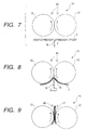
- Figure 7 is an illustration showing the manner in which the folding bar of the sheet bundle folding apparatus strikes against a bundle of sheets.
- Figure 8 is an illustration showing the manner in which the bundle of sheets is rolled in by a pair of fold rollers.
- Figure 9 is an illustration showing the state when the bundle of sheets has arrived at a second predetermined position.
- Figure 10 is an illustration showing the state when the pair of fold rollers has started its reverse rotation.
- Figure 11 is an illustration showing the state when the folded portion of the bundle of sheets passes the pair of fold rollers.
- Figure 12 is an illustration showing the state when the bundle of sheets has been liberated from the pair of fold rollers.
- Figure 13 is a cross-sectional view of a sheet folding apparatus according to another embodiment of the present invention.
- Figures 14A to 14F are operational illustrations showing the procedures of sheet folding apparatus according to another embodiment of the present invention, among which Figure 14A is a first operational illustration, Figure 14B is a second operational illustration, Figure 14C is a third operational illustration, Figure 14D is a fourth operational illustration, Figure 14E is a fifth operational illustration, and Figure 14F is a sixth operational illustration.
- Figure 15 is a flow chart showing the operational procedures of a sheet folding apparatus according to another embodiment of the present invention.
- Figure 16 is a schematic view showing the construction of an image forming apparatus provided with another sheet folding apparatus according to the present invention.
- Figure 17 shows one prior art.
- An image forming apparatus 4 as shown in Figure 1, is provided with a paper supply cassette 6 removably mounted in a main body 5 of the image forming apparatus (refer simply "apparatus body” hereinafter), a paper feeding roller 7, an image forming unit 8 and a sheet discharge device 9.
- This image forming apparatus 4 may specifically be a printer, a copying apparatus or a facsimile apparatus, and the image forming unit 8 may be of the optical type, the electrostatic type, the impact type, the laser beam type, the ink jet type or the thermal type.
- a sheet bundle folding apparatus 10 is mounted, for example, on one side of the apparatus body.
- This sheet bundle folding apparatus 10 has a supporting table 11 supporting thereon a bundle of sheets (not shown in Figure 2) having images formed thereon and discharged from a direction indicated by arrow A by a sheet discharge device 9, a fold roller pair 14 comprised of a pair of rollers 12 and 13 disposed above the supporting table 11 and urged against each other, a folding bar 16 which is a folding piece disposed below the supporting table 11 and is protruded to the supporting table 11 when the bundle of sheets is to be folded to thereby guide the bundle of sheets placed on the supporting table 11 to the nip portion (the pressure contact portion) 15 of the fold roller pair 14, a protruding device 17 which is protruding means for protruding the folding bar 16, and a pressure adjusting device 18 which is pressure force changing means for changing the pressure contact force of the rollers 12 and 13 which is the folding pressure of the fold roller pair 14.
- the reference character 11a designates a slot formed in the supporting table 11 in the lengthwise direction of the rollers 12 and 13, and the folding bar 16 is adapted to pass through this slot 11a and protrude to the supporting table 11.
- stoppers 11b are provided on one end portion of the supporting table 11 so that the bundle of sheet discharged may be stopped by the stoppers 11b at a position whereat the center of fold thereof faces the slot 11a.
- first roller 12 which is the fixed roller of the fold roller pair is rotatably held by the frame 10a of the sheet bundle folding apparatus 10 and a frame (not shown) on this side opposed to the frame 10a through bearings (not shown) and is adapted to be rotatively driven by a normally and reversely rotatable fold motor 19 which is drive means.
- the first roller 12 is adapted to be normally rotated when for example, the fold motor 19 is normally rotated, and when the first roller 12 is thus normally rotated, the other roller (hereinafter referred to as the "second roller") 13 which is a pivotally movable moving roller urged against the first roller 12 is reversely rotated.
- the fold roller pair 14 is rotated in a roll-in direction and thus, the bundle of sheets guided to the nip portion 15 by the folding bar 16 is rolled into the fold roller pair 14.
- design is made such that when the fold motor 19 is reversely rotated, the first roller 12 is reversely rotated, and when the first roller 12 is thus reversely rotated, the second roller 13 is normally rotated. Accordingly, when the fold motor 19 is normally rotated to thereby roll in the bundle of sheets and thereafter the fold motor 19 is reversely rotated, the first roller 12 is reversely rotated and the second roller 13 is normally rotated. Thus, the fold roller pair 14 is rotated in the return direction, whereby the rolled-in bundle of sheets is liberated from the fold roller pair 14 and is returned onto the supporting table 11.
- the reference character 20a denotes a first pulley mounted on the rotary shaft 19a of the fold motor 19
- the reference character 20b designates a second pulley mounted on the rotary shaft 12a of the first roller 12
- the reference numeral 21 denotes a belt passed over these two pulleys 20a and 20b.
- the rotation of the fold motor 19 may be transmitted to the first roller 12 through the first pulley 20a, the second pulley 20b and the belt 21.
- the second roller 13 is rotatably held on the upper end portion of a pressing plate 22 pivotally mounted on the frame on this side through a pivotally movable shaft 22a, through a bearing.
- the reference character 13a designates the rotary shaft of the second roller 13.
- the second roller 13 is thus held by the pivotally movable pressing plate 22, whereby even if the second roller 13 is in pressure contact with the first roller 12 when the bundle of sheets passes through the nip portion 15, the second roller 13 is pushed by the bundle of sheets and becomes movable away from the first roller 12 and thus, the bundle of sheets can pass through the nip portion 15 of the folding roller pair 14 without being jammed.
- the pressing plate 22 is connected to the pressure adjusting device 18 by a coil spring 23.
- This pressure adjusting device 18 pivotally moves the second roller 13 through the pressing plate 22 to thereby change the pressure contact force of the second roller 13 to a first pressure contact force or a second pressure contact force as will be described later.
- the device 18 is provided with the coil spring 23, a pressure varying plate 24 pivotally mounted on the frame on this side through a pivotally movable shaft 24a and having one end of the coil spring 23 restrained thereon, as shown in Figure 3, and a pivotally moving mechanism 26 for pivotally moving the pressure varying plate 24 by a cam 25.
- one end of the coil spring 22 is restrained on the upper end of the pressure varying plate 24 and the other end of the coil spring 22 is restrained on the lower end of the pressing plate 22 which is near the pressure varying plate 24.
- the pressure varying plate 24 is pivotally moved in a direction to pull the coil spring 23 by the cam 25, the pressing plate 22 is pulled by the coil spring 23 and is pivotally moved in a direction to bring the second roller 13 close to the first roller 12 side (hereinafter referred to as the "first roller direction").
- the pressure contact force of the second roller 13 against the first roller 12 becomes greater than the ordinary pressure contact force (hereinafter referred to as the "first pressure contact force") when the pressing plate 22 is not pivotally moved.
- first pressure contact force the ordinary pressure contact force
- second pressure contact force the second roller 13 is brought into pressure contact with the first roller 12, whereby great folding pressure can be applied to the bundle of sheets passing through the nip portion 15.
- great folding pressure being applied, the manner in which the bundle of sheets is folded can be improved.
- the pivotally moving mechanism 26 for pivotally moving the pressure varying plate 24 has the cam 25, a normally and reversely rotatable cam motor 27, a gear device 30 comprising a cam gear 28 mounted on a cam shaft 25a and a motor gear 29 mounted on the rotary shaft 27a of the cam motor 27 and meshing with the cam gear 28, and a first switch 31 and a second switch 32 for controlling the driving of the cam motor 27.
- the cam 25 is rotated by the rotation of the cam motor 27 transmitted thereto through the gear device 30 and presses the lower end portion of the pressure varying plate 24 to thereby pivotally move it in a direction to pull the coil spring 23, as shown in Figure 24.
- the pressure varying plate 24 is pivotally moved, the pressing plate 22 is pivotally moved in the first roller direction therewith.
- the first switch 31 When the pressing plate 22 is pivotally moved to a first predetermined position in which the second roller 13 can be brought into pressure contact with the first roller 12 by the second pressure contact force, the lower end portion of the pressure varying plate 24 pushes the first switch 31 as shown in Figure 4. Thus, the first switch 31 outputs a signal indicative of the fact that the pressing plate 22 has been pivotally moved to the first predetermined position to a control device which will be described later.
- the cam motor 27 is driven to thereby reversely rotate the cam 25.
- the pressure force of the cam 25 to the pressure varying plate 24 becomes null and thus, the pressure varying plate 24 and the pressing plate 22 are returned to their respective normal positions before the pivotal movement by the constrictive force of the coil spring 23, and the second roller 13 is brought into pressure contact with the first roller 12 with the first pressure contact force.
- the protruding device 17 for protruding the folding bar 16 is provided with a protrude arm 35 holding the folding bar 16 on one end portion thereof and having a curved rack 35a formed on the other end thereof, and a normally and reversely rotatable protrude motor 36 having mounted thereon a pinion 36a meshing with the rack 35a.
- the protrude arm 35 is pivotally held on the frame on this side through a pivotally movable shaft 35a.
- the folding bar 16 is mounted on the protrude arm 35 with a shaft 16a which is formed on the lower end of the folding bar loosely fitted in a laterally long slot 35b formed in one end portion of the protrude arm 35.
- a guide member for guiding the protrusion of the folding bar 16 adapted to be protruded in the direction of arrow B indicated in Figure 2, and when it is to be protruded, the folding bar 16 is protruded always in a vertical state while being guided by the guide member, whereby it can reliably guide the bundle of sheets to the nip portion 15.
- the protrude motor 36 is normally rotated for a first predetermined time in conformity with a drive signal from the control device to thereby pivotally move the protrude arm 35 in a direction to protrude the folding bar 16 (hereinafter referred to as the "protrude direction").
- This first predetermined time is a time during which the folding bar 16 can reliably cause the bundle of sheets to be rolled into the fold roller pair 14 and can be protruded by such a distance that it does not strike against the fold roller pair 14.
- the protrude motor 36 is designed to be reversely rotated for the same predetermined time in conformity with a drive signal from the control device after it has been normally rotated for the first predetermined time.
- the protrude arm 35 is pivotally moved in a direction to retract the folding bar 16 (hereinafter referred to as the "retract direction").
- control device 38 which is control means for driving and controlling the fold motor 19, the cam motor 27 and the protrude motor 36 to thereby control the sheet bundle folding operation, as shown in Figure 5, when the operate button 37 is depressed.
- a position sensor 40 which is position detecting means is disposed in a paper discharge path 39 provided near the fold roller pair 14, and in the present embodiment, above the fold roller pair 14.
- This sensor is for detecting that the bundle of sheets raised up after rolled in by the fold roller pair 14 has been raised to a second predetermined position in which it does not slip off the fold roller pair 14, and is comprised of a photosensor or the like.
- the detection signal from this position 40 is inputted to the control device 38.
- the control device 38 When the operate button 37 is depressed, the control device 38 firstly outputs a drive signal to the protrude motor 36 and the fold motor 19 to thereby normally rotate the protrude motor 36 for the first predetermined time and normally rotate the fold motor 19.
- the protrude motor 36 When the protrude motor 36 is thus normally rotated for the first predetermined time, the protrude arm 35 is pivotally moved in the protrude direction, whereby the folding bar 16 is protruded from the supporting table 11 and the bundle of sheets placed on the supporting table 11 is guided to the nip portion 15 of the fold roller pair 14.
- the fold roller pair 14 is rotated in the roll-in direction and the bundle of sheets guided by the folding bar 16 is rolled in.
- the control device 38 When the bundle of sheets is to be thus rolled in, the control device 38 does not output a drive signal to the cam motor 27, whereby the second roller 13 is brought into pressure contact with the first roller 12 with a first pressure contact force.
- the bundle of sheet is rolled into the fold roller pair 14 being in pressure contact with such small first pressure contact force, whereby the bundle of sheets can be easily rolled in even if the torque of the fold motor 19 is small and therefore, the fold motor 19 can be made compact.
- the control device 38 stops the protrude motor 36, while the rolled-in bundle of sheets is raised to a second predetermined position.
- the control device 38 stops the fold motor 19 and outputs a drive signal to the protrude motor 36 and the cam motor 27 to thereby reversely rotate the protrude motor 36 for the first predetermined time and normally rotate the cam motor 27.
- the protrude motor 36 When the protrude motor 36 is thus reversely rotated for the first predetermined time, the protrude arm 35 is pivotally moved in the retract direction and the folding bar 16 is retracted downwardly of the supporting table 11.
- the cam motor 27 When the cam motor 27 is normally rotated, the cam 25 presses the lower end portion of the pressure varying plate 24, whereby the pressure varying plate 24 is pivotally moved in a direction to pull the coil spring 23.
- the pressure varying plate 24 is thus pivotally moved, the pressing plate 22 is pulled by the coil spring 23 and is pivotally moved to a first predetermined position, and the second roller 13 is brought into pressure contact with the first roller 12 with a second pressure contact force.
- the first switch 31 When the pressure varying plate 24 pushed by the cam 25 is pivotally moved to thereby push the first switch 31, the first switch 31 outputs to the control device 38 a signal indicative of the fact that the pressing plate 22 has been pivotally moved to the first predetermined position. On the basis thereof, the control device 38 stops the cam motor 27 and the pressing plate 22 is held in the first predetermined position.
- the control device 38 outputs a drive signal to the fold motor 19 to thereby reversely rotate the fold motor 19 for a second predetermined time.
- the fold motor 19 is thus reversely rotated, the fold roller pair 14 is rotated in the return direction and the bundle of sheets which has so far been moved so as to be raised is lowered and is soon liberated from the folding roller pair 14 and is returned onto the supporting table.
- This second predetermined time is a time sufficient for the bundle of sheets to be lowered by the rotation of the fold roller pair 14 and thereafter be liberated from the folding roller pair 14 and returned onto the supporting table 11.
- the second roller 13 When the bundle of sheets is thus being lowered, the second roller 13 is in pressure contact with the first roller 12 with the second pressure contact force and therefore, when the leading end, i.e., the fold portion, of the bundle of sheets passes through the nip portion 15, greater folding pressure is applied to this fold portion. As a result, the bundle of sheets folded by the small first pressure contact force when first rolled in is folded more neatly when it is returned.
- the control device 38 outputs a drive signal to the cam motor 27 to thereby reversely rotate the cam motor 27.
- the cam 25 so far stopped in a position for keeping the pressing plate 22 in the first predetermined position is reversely rotated and the pressing plate 22 is returned to its normal position by the constrictive force of the coil spring 23, and the second roller 13 comes into pressure contact with the first roller 12 with the first pressure contact force.
- the cam 25 is adapted to push the second switch 32 when it is rotated to a position for returning the pressing plate 22 to its normal position, whereby the second switch 32 outputs to the control device 38 a signal indicative of the return of the pressing plate 22 to its normal position.
- the control device 38 stops the cam motor 27, whereby the pressing plate 22 is held in its normal position.
- control device 38 when the signal from the second switch 32 is inputted thereto, outputs a drive signal to the protrude motor 36 and the fold motor 19 to thereby normally rotate the fold motor 19 and normally rotate the protrude motor 36 for the first predetermined time.
- the folding bar 16 is protruded from the supporting table 11 so that the central portion of the neatly folded bundle of sheets may be rolled into the fold roller pair 14. The neatly folded bundle of sheets is thus again rolled in, whereby the bundle of sheets can be folded more neatly.
- the control device 38 when the bundle of sheets thus rolled in is raised to the second predetermined position, the signal from the position sensor 40 is inputted to the control device 38, whereby the control device 38 outputs a drive signal to the protrude motor 36 to thereby reversely rotate the protrude motor 36 for the first predetermined time and retract the folding bar 16 downwardly of the supporting table 11.
- the control device 38 reversely rotates the protrude motor 36, but normally rotates the fold motor 19.
- the bundle of sheets is neatly folded and is moved via the paper discharge path 39 to a take-out portion (not shown) formed above the paper discharge path 39, and is taken out from the take-out portion.
- control device 38 is adapted to detect that the folded bundle of sheets has been taken out by the fact that the signal from the position sensor 40 is no longer inputted, and to judge that the bundle of sheets has been taken out when the signal is no longer inputted, and stop the fold motor 19 and prepare for the next folding operation.
- the control device 38 When the operate button is depressed, the control device 38 first outputs a drive signal to the protrude motor 36 and the fold motor 19 to thereby normally rotate the protrude motor 36 for the first predetermined time (T1) and normally rotate the fold motor 19.
- T1 first predetermined time
- the folding bar 16 is protruded from the supporting table 11 and strikes against the bundle of sheets 3 placed on the supporting table 11.
- the bundle of sheets 3 is guided to the nip portion 15 of the fold roller pair 14, is rolled into the fold roller pair 14 being rotated in the roll-in direction indicated by an arrow, and is folded with the first pressure contact force at this time.
- the thus rolled-in bundle of sheets is raised to the second predetermined position, and a signal is inputted from the position sensor 40 which has detected this.
- the control device 38 stops the fold motor 19 and on the other hand, outputs a drive signal to the protrude motor 36 and the cam motor 27 to thereby reversely rotate the protrude motor 36 for the first predetermined time (T1) and normally rotate the cam motor 27.
- the protrude motor 36 When the protrude motor 36 is thus reversely rotated for the first predetermined time (T1), the protrude arm 35 is pivotally moved in the retract direction and the folding bar 16 is retracted downwardly of the supporting table 11. Also, when the cam motor 27 is normally rotated, the cam 25 presses the lower end portion of the pressure varying plate 24, whereby the pressure varying plate 24 is pivotally moved in a direction to pull the coil spring 23 and therewith, the pressing plate 22 is pivotally moved by the spring force of the coil spring 23. When this pressing plate 22 is pivotally moved to the first predetermined position, the first switch 31 is pushed by the pressure varying plate 24 and outputs to the control device 38 a signal indicative of the fact that the pressing plate 22 has been pivotally moved to the first predetermined position. On the basis of this signal, the control device 38 stops the cam motor 27 to thereby hold the pressing plate 22 in the first predetermined position.
- the control device 38 outputs a drive signal to the fold motor 19 to thereby reversely rotate the fold motor 19.
- the fold roller pair 14 is rotated in the return direction indicated by an arrow in Figure 10, whereby the bundle of sheets 3 so far moved so as to be raised is lowered.
- the second roller 13 When the bundle of sheets 3 is thus being lowered, the second roller 13 is in pressure contact with the first roller 12 with the second pressure contact force and therefore, when as shown in Figure 11, the upper end, i.e., the fold portion, of the bundle of sheets 3 passes the folding roller pair 14, a great pressure force is applied thereto and the state of fold becomes good.
- the fold motor 19 is thus reversely rotated for the second predetermined time (T2), the bundle of sheets 3 is liberated from the folding roller pair 14, as shown in Figure 12, and is returned onto the supporting table 11.
- the control device 38 outputs a device signal to the cam motor 27 to thereby reversely rotate the cam 25 so far stopped so as to keep the pressing plate 22 in the first predetermined position, and releases the pressing by the cam 25 to the pressure varying plate 24.
- the pressure varying plate 24 and the pressing plate 22 are returned to their respective normal positions before pivotal movement by the spring force of the coil spring 23 and therewith, the second roller 13 comes into pressure contact with the first roller 12 with the first pressure contact force.
- the second switch 32 is pushed by the cam 25 and outputs to the control device 38 a signal indicative of the fact that the pressing plate 22 has been returned to its normal position.
- the control device 38 stops the cam motor 27, whereby the pressing plate 22 is held in its normal position.
- the control device 38 when the detection signal from the second switch 32 is inputted to the control device 38, the control device 38 outputs a drive signal to the protrude motor 36 and the fold motor 19 to thereby normally rotate the fold motor 19 and normally rotate the protrude motor 36 for the first predetermined time (T1).
- T1 first predetermined time
- the control device 38 outputs a drive signal to the protrude motor 36 to thereby reversely rotate the protrude motor 36 for the first predetermined time (T1) and retract the folding bar 16 downwardly of the supporting table 11.
- the control device 38 continues to normally rotate the fold motor 19 and therefore, the bundle of sheets 3 is neatly folded and is moved to the take-out portion via the paper discharge path 39, and is taken out from this take-out portion.
- the control device 38 judges that the bundle of sheets 3 has been taken out, and stops the fold motor 19 and prepares for the next folding operation.
- the bundle of sheets 3 is folded with the small first pressure contact force when it is rolled in, whereafter the bundle of sheets 3 is folded with the great pressure contact force when it is returned onto the supporting table 11. Further, thereafter, the bundle of sheets 3 is folded with the first pressure contact force when it is again rolled in, whereby folding pressure can be applied to the bundle of sheets 3 three times and the folded state of the bundle of sheets can be made good.
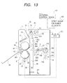
- Figure 13 schematically shows the construction of a sheet folding apparatus according to the present embodiment.
- a frame 1 is formed with entrance guides 31 and 32 for introducing sheets to be treated into the apparatus, and sheet guides 33 and 34 connected to the entrance guides 31 and 32.
- These entrance guides 31, 32 and sheet guides 33, 34 together constitute a first conveyance path 300.
- a second conveyance path 301 branching off from the first conveyance path 300 is formed in the course of the first conveyance path 300, and fold rollers (rotatable members) 2 and 3 are disposed on the branch-off portion 302 side thereof.
- the fold roller 3 is rotatably mounted on the frame 1 through a bearing, while the fold roller 2 is rotatably mounted on a pressing plate 15 through a bearing.
- the pressing plate 15 is pivotally movable about a pressing fulcrum 16 secured to the frame 1, and a spring 17 is restrained on one end thereof, and by this spring 17, the pressing plate 15 is normally biased counter-clockwisely about the pressing fulcrum 16. Accordingly, the fold roller 2 is adapted to be pressed against the fold roller 3 by the spring force of the spring 17.
- the fold roller 3 has a gear 22 secured coaxially therewith, and this gear 22 is in meshing engagement with the pinion gear 21 of a fold motor (stepping motor) 20. Accordingly, the drive force of the fold motor (rotatable member driving means) is transmitted to the fold roller 3 through the gears 21 and 22.
- Sheet protrude means 303 is disposed at a region (disposition portion 304) opposed to the branch-off portion 302 of the sheet guide 34 constituting the first conveyance path 300.
- This sheet protrude means 303 is provided with a protrude plate 8 protruding from an opening portion 304 to immediately the front of the nip portion between the fold rollers 2 and 3, and is adapted to be held by a protrude plate holding member 7.
- the protrude plate holding member 7 is adapted to be parallel-moved along a slot formed in the frame 1.
- Support shafts 11 are secured to the opposite sides of the protrude plate holding member 7, and one end (the left end as viewed in Figure 13) of a protrude arm 12 is pivotally fitted thereto.
- a support shaft 13c on a protrude drive plate 13b is pivotally fitted to the other end (the right end) of the protrude arm 12.
- the protrude drive plate 13b is disposed in pair in a direction perpendicular to the plane of the drawing sheet of Figure 13, and is secured to a protrude drive shaft 13a, on which a protrude drive gear 13d is secured.
- This protrude drive gear 13d is linked to the motor gear 14a of a protrude drive motor (stepping motor) 14 through an idle gear 14b, and the rotation of the protrude drive motor 14 is reduced and transmitted by the motor gear 14a secured on the output shaft of the motor and the idle gear 14b. Accordingly, the protrude drive shaft 13a is rotated by the rotation of the protrude drive motor 14, whereby the protrude drive plates 13b secured to the protrude drive shaft 13a are rotated. Thereby, the protrude arm 12 is pivotally moved so that the protrude plate holding member 7 may be parallel-moved (moved toward the nip portion between the fold rollers 2 and 3 as viewed in Figure 13).
- the sheet guides 33 and 34 disposed below the fold rollers 2 and 3 in Figure 13 have a sheet stopper 35 for regulating the leading end position of the sheet provided on the lower end portions thereof, and the sheet stopper 35 can be slidden in a vertical direction (arrows a and b) as viewed in Figure 13 by a lever (not shown) protruding outwardly of the apparatus. Consequently, if a user operates the lever in accordance with the size of a sheet to be folded, the sheet stopper will be moved in the direction of arrow a or b in Figure 13 in conformity with the amount of operation.
- Discharge guides 41 and 42 are located at the left side of the fold rollers 2 and 3 as viewed in Figure 13, and constitute the aforementioned second conveyance path 301.
- a discharge sensor 43 comprised of a transmission type photosensor for detecting the passage of the sheets.
- the folded bundle of sheets guided by the discharge guides 41 and 42 and discharged outwardly of the apparatus may be placed on a discharge tray 44.
- This sheet bundle thickness sensor 50 is disposed on the opening portion side of the entrance guides 31 and 32 and is adapted to detect the thickness of the bundle of sheets passing between the two guides 31 and 32.
- This sheet bundle thickness sensor 50 is provided with a sheet bundle thickness sensor flag (lever) 51 protruding into the first conveyance path 300, and a transmission type photosensor (sensor portion) 53, and the sheet bundle thickness sensor flag 51 is pivotally movable about a fulcrum 52.
- the sheet bundle thickness sensor flag 51 is normally biased clockwisely by a spring (not shown) and one end portion 51a thereof protrudes toward the entrance guide 31 side. When the bundle of sheets is inserted between the entrance guides 31 and 32, the sheet bundle thickness sensor flag 51 is pivotally moved in conformity with the thickness of the bundle of sheets.
- the other end portion 51b of the sheet bundle thickness sensor flag 51 interrupts the support shaft of the transmission type photosensor 53 and detects that the bundle of sheets has the predetermined thickness or greater.
- the detection signal is outputted from the transmission type photosensor 53 to a CPU 400 as control means.
- a sheet size lever (not shown) linked to the sheet stopper 35 is firstly operated to thereby move the sheet stopper 35 to a position coincident with the size of the sheets to be folded.
- the sheet bundle thickness sensor flag 51 contacts with the bundle of sheets and is pivotally moved, whereby whether the bundle of sheets has the predetermined thickness or greater is detected. Further, the bundle of sheets is guided along the sheet guides 33 and 34 and the leading end thereof strikes against the sheet stopper 35 and thus, the bundle of sheets is stopped.
- a start button (not shown) is depressed.
- the signal of this start button is inputted to the CPU 400, from which a control signal is thus outputted to the protrude drive motor 14 and the fold motor 20, whereby the protrude drive motor 14 and the fold motor 20 begin to be rotated. Since the rotation of the fold motor 20 is transmitted to the fold roller 3, the fold rollers 2 and 3 are rotated in the direction of arrow C in Figure 14A.
- the protrude plate 8 rams the bundle of sheets 9 against the fold rollers 2 and 3 while deforming it into a triangle. Thereupon, by the protruding force applied by the protrude plate 8, there is created a frictional force between the fold rollers 2, 3 and the bundle of sheets and further, due to the rotational forces of the fold rollers 2 and 3, the bundle of sheets 9 comes into the nip between the fold rollers 2 and 3. At that time, the protrude plate 8 bears against the stopper (not shown) and is prevented from moving toward the fold rollers 2 and 3, thus being prevented from coming into the nip between the fold rollers 2 and 3.
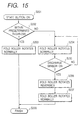
- the thickness data detected by the sheet bundle thickness sensor 50 is OFF, that is, the thickness of the bundle of sheets is less than the predetermined thickness (S202 in Figure 15), the fold rollers 2 and 3 are further rotated to thereby discharge the bundle of sheets 9 (S203).
- the bundle of sheets passes the discharge guides 41 and 42 and is discharged onto the discharge tray 44.
- the thickness data detected by the sheet bundle thickness sensor 50 is ON (S202), that is, the thickness of the bundle of sheets is the predetermined thickness or greater, the following operations are performed.
- the rotation of the fold motor 20 is stopped.
- the fold motor 20 is rotated in the opposite direction (S206) to thereby rotate the fold rollers 2 and 3 in the direction of arrow D indicated in Figure 14E.
- the rotation of the fold motor 20 is stopped ( Figure 14F).
- the number of normal and reverse revolutions of the folding rollers may be increased or decreased in conformity with the thickness of the bundle of sheets.
- the sheet bundle thickness detecting sensor is provided and folding is effected several times depending on the thickness of the bundle of sheets to be folded.
- sheet number information sent from the outside control device (sheet thickness output means) 401 of the copying apparatus or the like may be utilized.
- a sheet number detecting sensor (sheet thickness output means) 402 may be provided to convert the number of sheets to be folded into a thickness and determine the frequency of folding.
- sheet binding means capable of stapling substantially at the center of a bundle of sheets to be folded, carry out the aforedescribed folding of the bundle of sheets after binding the bundle of sheets, and make a double-spread pamphlet.
- Figure 16 shows an image forming apparatus 500 using the above-described sheet folding apparatus, and the sheet folding apparatus 503 of the present invention is connected to an image forming apparatus body 501.
- the sheet folding apparatus 503 has an accessory apparatus 502 for sheet introduction mounted on the upper portion of the frame 1.
- Such an image forming apparatus 500 forms images on sheets fed out of a cassette 505 or a cassette 506 in an image forming portion 507, and feeds out the sheets having the image formed thereon to the accessory apparatus 502 side by conveying rollers 508 and discharge rollers 509.
- the accessory apparatus 502 receives the sheets by introducing rollers 510, and counts the number of the sheets by sheet number counter means 511, whereafter it feeds the sheets into the sheet folding apparatus 503 for folding the sheets by guide rollers 512.
- An automatic original feeding device 504 is mounted on the upper portion of the image forming apparatus body 501, and original counter means 513 is disposed therein.
- a copy number setting button 514 is mounted on the image forming apparatus body 501.
- the above-described form is one in which the sheet folding apparatus 503 is used in combination with the image forming apparatus body 501 so as to automatically carry out the sheet folding process.
- the sheet folding apparatus 503 can also be used singly, and the accessory apparatus 502 will be unnecessary if design is made such that the first conveyance path 300 of the sheet folding apparatus 503 opens into the sheet discharge portion of the image forming apparatus body 501.
Landscapes
- Folding Of Thin Sheet-Like Materials, Special Discharging Devices, And Others (AREA)
Description
- This invention relates to a sheet folding apparatus for folding a bundle of sheet, and an image forming apparatus such as a copying apparatus, a printer or a facsimile apparatus provided with the sheet bundle folding apparatus, and more particularly relates to a sheet bundle folding apparatus for folding a bundle of sheet by a pair of folding rollers and an image forming apparatus provided with the same.
- As a sheet bundle folding apparatus mounted in an image forming apparatus such as a copier, printer or a facsimile apparatus, there is one described, for example, in EP 0 498 168 A, which corresponds to the preamble of
claim 1. This is provided with two sets of roller pairs, i.e. a pair of pre-fold rollers for folding a bundle of sheets after image formation and a pair of pressing rollers, and a folding bar for pushing the bundle of sheets into the nip between the pair of pre fold rollers. - In the sheet bundle folding apparatus of such a construction, design is made such that for example, the bundle of sheet after image formation is conveyed upwardly of the pair of pre-fold rollers, whereafter as shown in Figure 17 of the accompanying drawings, the
folding bar 1 is protruded toward the pair of pre-fold rollers 2 (e.g. downwardly). When thefolding bar 1 is thus protruded downwardly, the central portion of the bundle ofsheets 3 is pushed into thenip 2a between the pair ofpre-fold rollers 2 rotated in the roll-in direction indicated by an arrow, by thefolding bar 1, whereby the bundle ofsheets 3 is enfolded from the central portion thereof by the pair ofpre-fold rollers 2 and is folded into two. - Thereafter, the bundle of
sheets 3 folded into two by the pair ofpre-fold rollers 2 is rolled into a pair ofpressing rollers 2A disposed below the pair ofpre-fold rollers 2, and is further pressed by this pair ofpressing rollers 2A and is neatly folded into two. - Now, in such a sheet bundle folding apparatus according to the prior art, the fold height of the folded bundle of
sheets 3 and the drive torque for the pair of rollers required for folding are in an inverse proportional relation and therefore, a great drive torque will become necessary if an attempt is made to make the fold height low. For example, to neatly fold a sheet of A3 size (80 g/m2) into A4 size so that the fold height when it is placed on a flat surface may be of the order of 30 mm, a great drive torque of the order of 25 kg/cm becomes necessary as the drive torque for the pressing rollers. - To produce such a great drive torque, a large drive device becomes necessary, but there has been the problem that an attempt to provide such a large drive device leads to the bulkiness of the entire sheet bundle folding apparatus, which in turn leads to the bulkiness of the image forming apparatus.
- Also, the apparatus according to the prior art, as described above, is designed such that sheet folding is effected by the two sets of roller pairs, i.e., the pair of pre-fold rollers and the pair of pressing rollers and therefore, a drive device becomes necessary for each of the roller pairs, and this has led to the problem of complicated structure.
- The present invention has been made in view of the above-noted circumstances and a first object thereof is to provide a sheet bundle folding apparatus capable of neatly folding a bundle of sheet even by a drive device of small drive torque, and an image forming apparatus provided with the same.
- A second object of the present invention is to provide a sheet bundle folding apparatus which is simple and compact in structure and an image forming apparatus provided with the same.
- These objects are achieved by an apparatus according to
claim 1. - A sheet bundle folding apparatus for causing a bundle of sheets to be rolled into a pair of fold rollers and folding the bundle of sheets is provided with drive means for rotating the pair of fold rollers in a roll-in direction to roll in the bundle of sheets and a return direction to return the bundle of sheets, and particularly is provided with sheet bundle fold control means for controlling the drive means so that the pair of fold rollers may be rotated so as to roll in the bundle of sheets, and thereafter once return it, and again roll in the bundle of sheets, and on the other hand, controlling protrude means so as to protrude a folding piece from a supporting table when the pair of fold rollers are rotated in the roll-in direction, and to retract the folding piece from the supporting table when the pair of fold rollers are rotated in the return direction.
- Also, the sheet bundle fold control means controls the pressure contact force so as to be of an ordinary magnitude when the pair of folding rollers is rotated in the roll-in direction and controls the pressure contact force so as to become great when the pair of folding rollers is rotated in the return direction. Particularly, the pair of fold rollers are comprised of a fixed roller and a pivotally movable moving roller brought into pressure contact with the fixed roller, and the sheet bundle fold control means is provided with pivotally moving means for pivotally moving the moving roller so as to change the pressure contact force thereof with the fixed roller.
- Further, position detecting means for detecting the arrival of the rolled-in bundle of sheets at a predetermined position is provided near the pair of fold rollers, and the pair of fold rollers are rotated in the return direction on the basis of a detection signal from the position detecting means. Also, the present invention can likewise be applied to an image forming apparatus provided with an image forming unit and a sheet bundle folding apparatus for folding a bundle of sheets on which images have been formed by the image forming unit.
- On the basis of the above-described construction, the pair of fold rollers are rotated so as to roll in the bundle of sheets, and thereafter once return the bundle of sheets, and again roll in the bundle of sheets.
- Before the pair of fold rollers are rotated in the roll-in direction, the folding piece protrudes from the supporting table and thus, the bundle of sheets placed on the supporting table is rolled in by the pair of fold rollers. Also, when the pair of fold rollers are rotated in the return direction, the folding piece is retracted from the supporting table.
- Further, when the pair of fold rollers are rotated in the roll-in direction, the pressure contact force between the two rollers constituting the pair of fold rollers assumes an ordinary magnitude whereby the rolling-in of the bundle of sheets becomes easy. On the other hand, when the pair of fold rollers are rotated in the return direction, the pressure contact force becomes great, whereby the bundle of sheet can be neatly folded.
- Also, the pair of fold rollers are comprised of a fixed roller and a pivotally movable moving roller brought into pressure contact with the fixed roller, and the moving roller is pivotally moved by pivotally moving means, whereby the pressure contact force of the moving roller can be changed.
- Further, the arrival of the rolled-in bundle of sheets at a predetermined position is detected by the position detecting means provided near the pair of fold rollers, and the sheet bundle fold control means rotates the pair of fold rollers in the return direction on the basis of a detection signal outputted from the position detecting means.
- As described above, according to the present invention, the pair of fold rollers can be rotated so as to roll in the bundle of sheets, and thereafter once return it, and again roll in the bundle of sheets, to thereby apply folding pressure to the bundle of sheets a plurality of times. Therefore, the folding of the bundle of sheets can be effected by a pair of rollers and thus, the structure can be simplified.
- Also, when the pair of fold rollers are rotated in the roll-in direction, the folding pressure of the pair of fold rollers can be made small to thereby make the rolling-in of the bundle of sheets easy, and when the pair of fold rollers are rotated in the return direction, the folding pressure can be made great to thereby fold the bundle of sheets neatly even by a drive device of small drive torque.
- Also, in the case of a thick sheet, it is folded a plurality of times or the frequency of folding is increased, whereby the accuracy of folding can be enhanced. On the other hand, in the case of a sheet of a predetermined thickness or less, a plurality of times of folding is not effected or the frequency of folding is decreased and therefore, it becomes possible to enhance productivity. This is because when the thickness of a bundle of sheets (the number of sheets) is small, the returning operation is not performed or the frequency of folding is small and therefore the waste of time becomes null.
- Further, by such a sheet bundle folding apparatus being applied to an image forming apparatus, a bundle of sheet can be folded neatly even by a compact drive device of small drive torque.
- Figure 1 is a schematic view showing the whole of an image forming apparatus according to the present invention.
- Figure 2 is a perspective view showing the internal structure of a sheet bundle folding apparatus disposed in the image forming apparatus of Figure 1.
- Figure 3 is an illustration showing the structure of the pressure adjusting device of the sheet bundle folding apparatus of Figure 2.
- Figure 4 is an illustration showing the manner in which a pressing plate is pivotally moved by the pressure adjusting device of Figure 3.
- Figure 5 is a block diagram of the control device of the sheet bundle folding apparatus.
- Figure 6 is a timing chart for driving the various motors of the sheet bundle folding apparatus.
- Figure 7 is an illustration showing the manner in which the folding bar of the sheet bundle folding apparatus strikes against a bundle of sheets.
- Figure 8 is an illustration showing the manner in which the bundle of sheets is rolled in by a pair of fold rollers.
- Figure 9 is an illustration showing the state when the bundle of sheets has arrived at a second predetermined position.
- Figure 10 is an illustration showing the state when the pair of fold rollers has started its reverse rotation.
- Figure 11 is an illustration showing the state when the folded portion of the bundle of sheets passes the pair of fold rollers.
- Figure 12 is an illustration showing the state when the bundle of sheets has been liberated from the pair of fold rollers.
- Figure 13 is a cross-sectional view of a sheet folding apparatus according to another embodiment of the present invention.
- Figures 14A to 14F are operational illustrations showing the procedures of sheet folding apparatus according to another embodiment of the present invention, among which Figure 14A is a first operational illustration, Figure 14B is a second operational illustration, Figure 14C is a third operational illustration, Figure 14D is a fourth operational illustration, Figure 14E is a fifth operational illustration, and Figure 14F is a sixth operational illustration.
- Figure 15 is a flow chart showing the operational procedures of a sheet folding apparatus according to another embodiment of the present invention.
- Figure 16 is a schematic view showing the construction of an image forming apparatus provided with another sheet folding apparatus according to the present invention.
- Figure 17 shows one prior art.
- Some embodiments of the present invention will hereinafter be described with reference to the drawings.
- An image forming apparatus 4, as shown in Figure 1, is provided with a paper supply cassette 6 removably mounted in a main body 5 of the image forming apparatus (refer simply "apparatus body" hereinafter), a
paper feeding roller 7, animage forming unit 8 and asheet discharge device 9. This image forming apparatus 4 may specifically be a printer, a copying apparatus or a facsimile apparatus, and theimage forming unit 8 may be of the optical type, the electrostatic type, the impact type, the laser beam type, the ink jet type or the thermal type. - On the other hand, a sheet
bundle folding apparatus 10 is mounted, for example, on one side of the apparatus body. This sheetbundle folding apparatus 10, as shown in Figure 2, has a supporting table 11 supporting thereon a bundle of sheets (not shown in Figure 2) having images formed thereon and discharged from a direction indicated by arrow A by asheet discharge device 9, afold roller pair 14 comprised of a pair ofrollers folding bar 16 which is a folding piece disposed below the supporting table 11 and is protruded to the supporting table 11 when the bundle of sheets is to be folded to thereby guide the bundle of sheets placed on the supporting table 11 to the nip portion (the pressure contact portion) 15 of thefold roller pair 14, aprotruding device 17 which is protruding means for protruding thefolding bar 16, and apressure adjusting device 18 which is pressure force changing means for changing the pressure contact force of therollers fold roller pair 14. - In Figure 2, the
reference character 11a designates a slot formed in the supporting table 11 in the lengthwise direction of therollers folding bar 16 is adapted to pass through thisslot 11a and protrude to the supporting table 11. Also,stoppers 11b are provided on one end portion of the supporting table 11 so that the bundle of sheet discharged may be stopped by thestoppers 11b at a position whereat the center of fold thereof faces theslot 11a. Thus, when thefolding bar 16 is protruded, the bundle of sheets is adapted to be pushed up by thefolding bar 16 as an angled shape with the center as the vertex. - Now, one roller (hereinafter referred to as the "first roller") 12 which is the fixed roller of the fold roller pair is rotatably held by the
frame 10a of the sheetbundle folding apparatus 10 and a frame (not shown) on this side opposed to theframe 10a through bearings (not shown) and is adapted to be rotatively driven by a normally and reverselyrotatable fold motor 19 which is drive means. - The
first roller 12 is adapted to be normally rotated when for example, thefold motor 19 is normally rotated, and when thefirst roller 12 is thus normally rotated, the other roller (hereinafter referred to as the "second roller") 13 which is a pivotally movable moving roller urged against thefirst roller 12 is reversely rotated. When thefirst roller 12 is normally rotated and thesecond roller 13 is reversely rotated as described above, thefold roller pair 14 is rotated in a roll-in direction and thus, the bundle of sheets guided to thenip portion 15 by thefolding bar 16 is rolled into thefold roller pair 14. - Also, design is made such that when the
fold motor 19 is reversely rotated, thefirst roller 12 is reversely rotated, and when thefirst roller 12 is thus reversely rotated, thesecond roller 13 is normally rotated. Accordingly, when thefold motor 19 is normally rotated to thereby roll in the bundle of sheets and thereafter thefold motor 19 is reversely rotated, thefirst roller 12 is reversely rotated and thesecond roller 13 is normally rotated. Thus, thefold roller pair 14 is rotated in the return direction, whereby the rolled-in bundle of sheets is liberated from thefold roller pair 14 and is returned onto the supporting table 11. - In Figure 2, the
reference character 20a denotes a first pulley mounted on therotary shaft 19a of thefold motor 19, thereference character 20b designates a second pulley mounted on therotary shaft 12a of thefirst roller 12, and thereference numeral 21 denotes a belt passed over these twopulleys fold motor 19 may be transmitted to thefirst roller 12 through thefirst pulley 20a, thesecond pulley 20b and thebelt 21. On the other hand, thesecond roller 13 is rotatably held on the upper end portion of apressing plate 22 pivotally mounted on the frame on this side through a pivotallymovable shaft 22a, through a bearing. Thereference character 13a designates the rotary shaft of thesecond roller 13. - The
second roller 13 is thus held by the pivotally movable pressingplate 22, whereby even if thesecond roller 13 is in pressure contact with thefirst roller 12 when the bundle of sheets passes through thenip portion 15, thesecond roller 13 is pushed by the bundle of sheets and becomes movable away from thefirst roller 12 and thus, the bundle of sheets can pass through thenip portion 15 of thefolding roller pair 14 without being jammed. - Now, the
pressing plate 22 is connected to thepressure adjusting device 18 by acoil spring 23. Thispressure adjusting device 18 pivotally moves thesecond roller 13 through thepressing plate 22 to thereby change the pressure contact force of thesecond roller 13 to a first pressure contact force or a second pressure contact force as will be described later. Thedevice 18 is provided with thecoil spring 23, apressure varying plate 24 pivotally mounted on the frame on this side through a pivotallymovable shaft 24a and having one end of thecoil spring 23 restrained thereon, as shown in Figure 3, and a pivotally movingmechanism 26 for pivotally moving thepressure varying plate 24 by acam 25. The pivotally movingmechanism 26 and thepressure varying plate 24 together constitute pivotally moving means for pivotally moving thesecond roller 13, and when thepressure varying plate 24 is pivotally moved by the pivotally movingmechanism 26, thepressing plate 22 having the other end of thecoil spring 23 restrained thereon as shown in Figure 4 may be pulled and pivotally moved by thecoil spring 23. - In the present embodiment, as shown in Figure 4, one end of the
coil spring 22 is restrained on the upper end of thepressure varying plate 24 and the other end of thecoil spring 22 is restrained on the lower end of thepressing plate 22 which is near thepressure varying plate 24. By thecoil spring 23 being mounted in such a relation, when as will be described later, thepressure varying plate 24 is pivotally moved in a direction to pull thecoil spring 23 by thecam 25, thepressing plate 22 is pulled by thecoil spring 23 and is pivotally moved in a direction to bring thesecond roller 13 close to thefirst roller 12 side (hereinafter referred to as the "first roller direction"). - When the
pressing plate 22 is thus pivotally moved in the first roller direction and thesecond roller 13 comes close to thefirst roller 12, the pressure contact force of thesecond roller 13 against thefirst roller 12 becomes greater than the ordinary pressure contact force (hereinafter referred to as the "first pressure contact force") when thepressing plate 22 is not pivotally moved. By such a great pressure contact force (hereinafter referred to as the "second pressure contact force"), thesecond roller 13 is brought into pressure contact with thefirst roller 12, whereby great folding pressure can be applied to the bundle of sheets passing through thenip portion 15. By such great folding pressure being applied, the manner in which the bundle of sheets is folded can be improved. - Now, the pivotally moving
mechanism 26 for pivotally moving thepressure varying plate 24 has thecam 25, a normally and reverselyrotatable cam motor 27, agear device 30 comprising acam gear 28 mounted on acam shaft 25a and amotor gear 29 mounted on therotary shaft 27a of thecam motor 27 and meshing with thecam gear 28, and afirst switch 31 and asecond switch 32 for controlling the driving of thecam motor 27. - The
cam 25 is rotated by the rotation of thecam motor 27 transmitted thereto through thegear device 30 and presses the lower end portion of thepressure varying plate 24 to thereby pivotally move it in a direction to pull thecoil spring 23, as shown in Figure 24. When thepressure varying plate 24 is pivotally moved, thepressing plate 22 is pivotally moved in the first roller direction therewith. - When the
pressing plate 22 is pivotally moved to a first predetermined position in which thesecond roller 13 can be brought into pressure contact with thefirst roller 12 by the second pressure contact force, the lower end portion of thepressure varying plate 24 pushes thefirst switch 31 as shown in Figure 4. Thus, thefirst switch 31 outputs a signal indicative of the fact that thepressing plate 22 has been pivotally moved to the first predetermined position to a control device which will be described later. - On the other hand, when the
pressing plate 22 is to be returned from the first predetermined position to the normal position before the pivotal movement, that is, the pressure contact force of thesecond roller 13 is to be returned from the second pressure contact force to the first pressure contact force, thecam motor 27 is driven to thereby reversely rotate thecam 25. Thereby, the pressure force of thecam 25 to thepressure varying plate 24 becomes null and thus, thepressure varying plate 24 and thepressing plate 22 are returned to their respective normal positions before the pivotal movement by the constrictive force of thecoil spring 23, and thesecond roller 13 is brought into pressure contact with thefirst roller 12 with the first pressure contact force. - When the
cam 25 is rotated to a position in which thepressing plate 22 is returned to the normal position, it pushes thesecond switch 32, as shown in Figure 3, and the second switch outputs to the control device a signal indicative of the return of thepressing plate 22 to the normal position. - On the other hand, the protruding
device 17 for protruding thefolding bar 16, as shown in Figure 2, is provided with aprotrude arm 35 holding thefolding bar 16 on one end portion thereof and having acurved rack 35a formed on the other end thereof, and a normally and reverselyrotatable protrude motor 36 having mounted thereon apinion 36a meshing with therack 35a. Theprotrude arm 35 is pivotally held on the frame on this side through a pivotallymovable shaft 35a. Thefolding bar 16 is mounted on theprotrude arm 35 with a shaft 16a which is formed on the lower end of the folding bar loosely fitted in a laterallylong slot 35b formed in one end portion of theprotrude arm 35. By the shaft 16a being thus loosely fitted in theslot 35b, when theprotrude arm 35 is pivotally moved, thefolding bar 16 can always keep a predetermined protruding posture while sliding the shaft 16a. - On the lower surface of the supporting table 11, there is provided a guide member (not shown) for guiding the protrusion of the
folding bar 16 adapted to be protruded in the direction of arrow B indicated in Figure 2, and when it is to be protruded, thefolding bar 16 is protruded always in a vertical state while being guided by the guide member, whereby it can reliably guide the bundle of sheets to the nipportion 15. - Now, when an operate
button 37 shown in Figure 5 which will be described later and which is provided to start the sheetbundle folding apparatus 10 is depressed, theprotrude motor 36 is normally rotated for a first predetermined time in conformity with a drive signal from the control device to thereby pivotally move theprotrude arm 35 in a direction to protrude the folding bar 16 (hereinafter referred to as the "protrude direction"). This first predetermined time is a time during which thefolding bar 16 can reliably cause the bundle of sheets to be rolled into thefold roller pair 14 and can be protruded by such a distance that it does not strike against thefold roller pair 14. Also, theprotrude motor 36 is designed to be reversely rotated for the same predetermined time in conformity with a drive signal from the control device after it has been normally rotated for the first predetermined time. Thus, theprotrude arm 35 is pivotally moved in a direction to retract the folding bar 16 (hereinafter referred to as the "retract direction"). - On the other hand, at a predetermined location in the sheet
bundle folding apparatus 10, there is disposed acontrol device 38 which is control means for driving and controlling thefold motor 19, thecam motor 27 and theprotrude motor 36 to thereby control the sheet bundle folding operation, as shown in Figure 5, when the operatebutton 37 is depressed. - As shown in Figure 2, a
position sensor 40 which is position detecting means is disposed in apaper discharge path 39 provided near thefold roller pair 14, and in the present embodiment, above thefold roller pair 14. This sensor is for detecting that the bundle of sheets raised up after rolled in by thefold roller pair 14 has been raised to a second predetermined position in which it does not slip off thefold roller pair 14, and is comprised of a photosensor or the like. The detection signal from thisposition 40 is inputted to thecontrol device 38. - When the operate
button 37 is depressed, thecontrol device 38 firstly outputs a drive signal to theprotrude motor 36 and thefold motor 19 to thereby normally rotate theprotrude motor 36 for the first predetermined time and normally rotate thefold motor 19. When theprotrude motor 36 is thus normally rotated for the first predetermined time, theprotrude arm 35 is pivotally moved in the protrude direction, whereby thefolding bar 16 is protruded from the supporting table 11 and the bundle of sheets placed on the supporting table 11 is guided to the nipportion 15 of thefold roller pair 14. Also, when thefold motor 19 is normally rotated, thefold roller pair 14 is rotated in the roll-in direction and the bundle of sheets guided by thefolding bar 16 is rolled in. - When the bundle of sheets is to be thus rolled in, the
control device 38 does not output a drive signal to thecam motor 27, whereby thesecond roller 13 is brought into pressure contact with thefirst roller 12 with a first pressure contact force. The bundle of sheet is rolled into thefold roller pair 14 being in pressure contact with such small first pressure contact force, whereby the bundle of sheets can be easily rolled in even if the torque of thefold motor 19 is small and therefore, thefold motor 19 can be made compact. - Also, when the first predetermined time elapses, the
control device 38 stops theprotrude motor 36, while the rolled-in bundle of sheets is raised to a second predetermined position. When the detection signal from theposition sensor 40 which has detected this is inputted to thecontrol device 38, thecontrol device 38 stops thefold motor 19 and outputs a drive signal to theprotrude motor 36 and thecam motor 27 to thereby reversely rotate theprotrude motor 36 for the first predetermined time and normally rotate thecam motor 27. - When the
protrude motor 36 is thus reversely rotated for the first predetermined time, theprotrude arm 35 is pivotally moved in the retract direction and thefolding bar 16 is retracted downwardly of the supporting table 11. When thecam motor 27 is normally rotated, thecam 25 presses the lower end portion of thepressure varying plate 24, whereby thepressure varying plate 24 is pivotally moved in a direction to pull thecoil spring 23. When thepressure varying plate 24 is thus pivotally moved, thepressing plate 22 is pulled by thecoil spring 23 and is pivotally moved to a first predetermined position, and thesecond roller 13 is brought into pressure contact with thefirst roller 12 with a second pressure contact force. - When the
pressure varying plate 24 pushed by thecam 25 is pivotally moved to thereby push thefirst switch 31, thefirst switch 31 outputs to the control device 38 a signal indicative of the fact that thepressing plate 22 has been pivotally moved to the first predetermined position. On the basis thereof, thecontrol device 38 stops thecam motor 27 and thepressing plate 22 is held in the first predetermined position. - On the other hand, after the
pressing plate 22 has been held in the first predetermined position, thecontrol device 38 outputs a drive signal to thefold motor 19 to thereby reversely rotate thefold motor 19 for a second predetermined time. When thefold motor 19 is thus reversely rotated, thefold roller pair 14 is rotated in the return direction and the bundle of sheets which has so far been moved so as to be raised is lowered and is soon liberated from thefolding roller pair 14 and is returned onto the supporting table. This second predetermined time is a time sufficient for the bundle of sheets to be lowered by the rotation of thefold roller pair 14 and thereafter be liberated from thefolding roller pair 14 and returned onto the supporting table 11. - When the bundle of sheets is thus being lowered, the
second roller 13 is in pressure contact with thefirst roller 12 with the second pressure contact force and therefore, when the leading end, i.e., the fold portion, of the bundle of sheets passes through thenip portion 15, greater folding pressure is applied to this fold portion. As a result, the bundle of sheets folded by the small first pressure contact force when first rolled in is folded more neatly when it is returned. - Now, after the
fold motor 19 is thus reversely rotated for the second predetermined time to thereby liberate the bundle of sheets, thecontrol device 38 outputs a drive signal to thecam motor 27 to thereby reversely rotate thecam motor 27. Thereby, thecam 25 so far stopped in a position for keeping thepressing plate 22 in the first predetermined position is reversely rotated and thepressing plate 22 is returned to its normal position by the constrictive force of thecoil spring 23, and thesecond roller 13 comes into pressure contact with thefirst roller 12 with the first pressure contact force. - The
cam 25 is adapted to push thesecond switch 32 when it is rotated to a position for returning thepressing plate 22 to its normal position, whereby thesecond switch 32 outputs to the control device 38 a signal indicative of the return of thepressing plate 22 to its normal position. On the basis thereof, thecontrol device 38 stops thecam motor 27, whereby thepressing plate 22 is held in its normal position. - On the other hand, the
control device 38, when the signal from thesecond switch 32 is inputted thereto, outputs a drive signal to theprotrude motor 36 and thefold motor 19 to thereby normally rotate thefold motor 19 and normally rotate theprotrude motor 36 for the first predetermined time. When theprotrude motor 36 is thus normally rotated for the first predetermined time, thefolding bar 16 is protruded from the supporting table 11 so that the central portion of the neatly folded bundle of sheets may be rolled into thefold roller pair 14. The neatly folded bundle of sheets is thus again rolled in, whereby the bundle of sheets can be folded more neatly. - Now, when the bundle of sheets thus rolled in is raised to the second predetermined position, the signal from the
position sensor 40 is inputted to thecontrol device 38, whereby thecontrol device 38 outputs a drive signal to theprotrude motor 36 to thereby reversely rotate theprotrude motor 36 for the first predetermined time and retract thefolding bar 16 downwardly of the supporting table 11. However, unlike the case where the signal from theposition sensor 40 has been inputted for the first time, thecontrol device 38 reversely rotates theprotrude motor 36, but normally rotates thefold motor 19. Thereby, the bundle of sheets is neatly folded and is moved via thepaper discharge path 39 to a take-out portion (not shown) formed above thepaper discharge path 39, and is taken out from the take-out portion. - In the present embodiment, the
control device 38 is adapted to detect that the folded bundle of sheets has been taken out by the fact that the signal from theposition sensor 40 is no longer inputted, and to judge that the bundle of sheets has been taken out when the signal is no longer inputted, and stop thefold motor 19 and prepare for the next folding operation. - The action of the above-described embodiment will now be described with reference to a timing chart shown in Figure 6.
- When the operate button is depressed, the
control device 38 first outputs a drive signal to theprotrude motor 36 and thefold motor 19 to thereby normally rotate theprotrude motor 36 for the first predetermined time (T1) and normally rotate thefold motor 19. Thereby, as shown in Figure 7, thefolding bar 16 is protruded from the supporting table 11 and strikes against the bundle ofsheets 3 placed on the supporting table 11. As shown in Figure 8, by thisfolding bar 16, the bundle ofsheets 3 is guided to the nipportion 15 of thefold roller pair 14, is rolled into thefold roller pair 14 being rotated in the roll-in direction indicated by an arrow, and is folded with the first pressure contact force at this time. - On the other hand, the thus rolled-in bundle of sheets, as shown in Figure 9, is raised to the second predetermined position, and a signal is inputted from the
position sensor 40 which has detected this. Thereupon, thecontrol device 38 stops thefold motor 19 and on the other hand, outputs a drive signal to theprotrude motor 36 and thecam motor 27 to thereby reversely rotate theprotrude motor 36 for the first predetermined time (T1) and normally rotate thecam motor 27. - When the
protrude motor 36 is thus reversely rotated for the first predetermined time (T1), theprotrude arm 35 is pivotally moved in the retract direction and thefolding bar 16 is retracted downwardly of the supporting table 11. Also, when thecam motor 27 is normally rotated, thecam 25 presses the lower end portion of thepressure varying plate 24, whereby thepressure varying plate 24 is pivotally moved in a direction to pull thecoil spring 23 and therewith, thepressing plate 22 is pivotally moved by the spring force of thecoil spring 23. When thispressing plate 22 is pivotally moved to the first predetermined position, thefirst switch 31 is pushed by thepressure varying plate 24 and outputs to the control device 38 a signal indicative of the fact that thepressing plate 22 has been pivotally moved to the first predetermined position. On the basis of this signal, thecontrol device 38 stops thecam motor 27 to thereby hold thepressing plate 22 in the first predetermined position. - On the other hand, after having thus held the
pressing plate 22 in the first predetermined position, thecontrol device 38 outputs a drive signal to thefold motor 19 to thereby reversely rotate thefold motor 19. Thereby, thefold roller pair 14 is rotated in the return direction indicated by an arrow in Figure 10, whereby the bundle ofsheets 3 so far moved so as to be raised is lowered. - When the bundle of
sheets 3 is thus being lowered, thesecond roller 13 is in pressure contact with thefirst roller 12 with the second pressure contact force and therefore, when as shown in Figure 11, the upper end, i.e., the fold portion, of the bundle ofsheets 3 passes thefolding roller pair 14, a great pressure force is applied thereto and the state of fold becomes good. When thefold motor 19 is thus reversely rotated for the second predetermined time (T2), the bundle ofsheets 3 is liberated from thefolding roller pair 14, as shown in Figure 12, and is returned onto the supporting table 11. - Thereafter, the
control device 38 outputs a device signal to thecam motor 27 to thereby reversely rotate thecam 25 so far stopped so as to keep thepressing plate 22 in the first predetermined position, and releases the pressing by thecam 25 to thepressure varying plate 24. Thereby, thepressure varying plate 24 and thepressing plate 22 are returned to their respective normal positions before pivotal movement by the spring force of thecoil spring 23 and therewith, thesecond roller 13 comes into pressure contact with thefirst roller 12 with the first pressure contact force. When thepressing plate 22 is thus returned to its normal position, thesecond switch 32 is pushed by thecam 25 and outputs to the control device 38 a signal indicative of the fact that thepressing plate 22 has been returned to its normal position. On the basis of this, thecontrol device 38 stops thecam motor 27, whereby thepressing plate 22 is held in its normal position. - On the other hand, when the detection signal from the
second switch 32 is inputted to thecontrol device 38, thecontrol device 38 outputs a drive signal to theprotrude motor 36 and thefold motor 19 to thereby normally rotate thefold motor 19 and normally rotate theprotrude motor 36 for the first predetermined time (T1). Thereby, thefolding bar 16 is protruded from the supporting table 11 and the central portion of the neatly folded bundle of sheets is guided to thefold roller pair 14 by thefolding bar 16 and is rolled into thefold roller pair 14. - Also, when the thus rolled-in bundle of sheets is raised to the second predetermined position (see Figure 9), the signal from the
position sensor 40 is inputted to thecontrol device 38. Thus, thecontrol device 38 outputs a drive signal to theprotrude motor 36 to thereby reversely rotate theprotrude motor 36 for the first predetermined time (T1) and retract thefolding bar 16 downwardly of the supporting table 11. - When the second signal is thus inputted from the
position sensor 40, thecontrol device 38 continues to normally rotate thefold motor 19 and therefore, the bundle ofsheets 3 is neatly folded and is moved to the take-out portion via thepaper discharge path 39, and is taken out from this take-out portion. When the bundle ofsheets 3 is thus taken out and the signal from theposition sensor 40 is no longer inputted, thecontrol device 38 judges that the bundle ofsheets 3 has been taken out, and stops thefold motor 19 and prepares for the next folding operation. - As described above, the bundle of
sheets 3 is folded with the small first pressure contact force when it is rolled in, whereafter the bundle ofsheets 3 is folded with the great pressure contact force when it is returned onto the supporting table 11. Further, thereafter, the bundle ofsheets 3 is folded with the first pressure contact force when it is again rolled in, whereby folding pressure can be applied to the bundle ofsheets 3 three times and the folded state of the bundle of sheets can be made good. - In the foregoing, description has been made of the apparatus in which the
protrude motor 36 is normally rotated for the first predetermined time, whereby thefolding bar 16 does not strike against thefold roller pair 14. The present invention, however, is not restricted to it, but a stopper against which thefolding bar 16 protruded to the position for guiding the bundle ofsheets 3 strikes may be provided, for example, between the supporting table 11 and thefold roller pair 14, whereby thefolding bar 16 can be more reliably prevented from striking against thefold roller pair 14. Also, while in the foregoing, the bundle of sheets to be folded has been described as being not stapled on the supporting table 11 in thesheet discharge device 9 after image formation, the present invention is also applicable to a bundle of sheets stapled at the central position thereof. - Another embodiment of the present invention will now be described in detail with reference to the drawings.
- Figure 13 schematically shows the construction of a sheet folding apparatus according to the present embodiment.
- As shown in Figure 13, a
frame 1 is formed with entrance guides 31 and 32 for introducing sheets to be treated into the apparatus, and sheet guides 33 and 34 connected to the entrance guides 31 and 32. These entrance guides 31, 32 and sheet guides 33, 34 together constitute afirst conveyance path 300. - A
second conveyance path 301 branching off from thefirst conveyance path 300 is formed in the course of thefirst conveyance path 300, and fold rollers (rotatable members) 2 and 3 are disposed on the branch-offportion 302 side thereof. Thefold roller 3 is rotatably mounted on theframe 1 through a bearing, while thefold roller 2 is rotatably mounted on apressing plate 15 through a bearing. Thepressing plate 15 is pivotally movable about apressing fulcrum 16 secured to theframe 1, and aspring 17 is restrained on one end thereof, and by thisspring 17, thepressing plate 15 is normally biased counter-clockwisely about thepressing fulcrum 16. Accordingly, thefold roller 2 is adapted to be pressed against thefold roller 3 by the spring force of thespring 17. - The
fold roller 3 has agear 22 secured coaxially therewith, and thisgear 22 is in meshing engagement with thepinion gear 21 of a fold motor (stepping motor) 20. Accordingly, the drive force of the fold motor (rotatable member driving means) is transmitted to thefold roller 3 through thegears - Sheet protrude means 303 is disposed at a region (disposition portion 304) opposed to the branch-off
portion 302 of thesheet guide 34 constituting thefirst conveyance path 300. This sheet protrude means 303 is provided with aprotrude plate 8 protruding from anopening portion 304 to immediately the front of the nip portion between thefold rollers plate holding member 7. The protrudeplate holding member 7 is adapted to be parallel-moved along a slot formed in theframe 1.Support shafts 11 are secured to the opposite sides of the protrudeplate holding member 7, and one end (the left end as viewed in Figure 13) of aprotrude arm 12 is pivotally fitted thereto. Asupport shaft 13c on aprotrude drive plate 13b is pivotally fitted to the other end (the right end) of theprotrude arm 12. - The
protrude drive plate 13b is disposed in pair in a direction perpendicular to the plane of the drawing sheet of Figure 13, and is secured to aprotrude drive shaft 13a, on which aprotrude drive gear 13d is secured. Thisprotrude drive gear 13d is linked to themotor gear 14a of a protrude drive motor (stepping motor) 14 through anidle gear 14b, and the rotation of theprotrude drive motor 14 is reduced and transmitted by themotor gear 14a secured on the output shaft of the motor and theidle gear 14b. Accordingly, theprotrude drive shaft 13a is rotated by the rotation of theprotrude drive motor 14, whereby theprotrude drive plates 13b secured to theprotrude drive shaft 13a are rotated. Thereby, theprotrude arm 12 is pivotally moved so that the protrudeplate holding member 7 may be parallel-moved (moved toward the nip portion between thefold rollers - The sheet guides 33 and 34 disposed below the
fold rollers sheet stopper 35 for regulating the leading end position of the sheet provided on the lower end portions thereof, and thesheet stopper 35 can be slidden in a vertical direction (arrows a and b) as viewed in Figure 13 by a lever (not shown) protruding outwardly of the apparatus. Consequently, if a user operates the lever in accordance with the size of a sheet to be folded, the sheet stopper will be moved in the direction of arrow a or b in Figure 13 in conformity with the amount of operation. - Discharge guides 41 and 42 are located at the left side of the
fold rollers second conveyance path 301. On the atmosphere side (the left side as viewed in Figure 13) end portion of the discharge guides 41 and 42, there is disposed adischarge sensor 43 comprised of a transmission type photosensor for detecting the passage of the sheets. The folded bundle of sheets guided by the discharge guides 41 and 42 and discharged outwardly of the apparatus may be placed on adischarge tray 44. - Description will now be made of a sheet bundle thickness sensor (sheet thickness output means) 50 used in the sheet folding apparatus according to the present embodiment.
- This sheet
bundle thickness sensor 50 is disposed on the opening portion side of the entrance guides 31 and 32 and is adapted to detect the thickness of the bundle of sheets passing between the twoguides bundle thickness sensor 50 is provided with a sheet bundle thickness sensor flag (lever) 51 protruding into thefirst conveyance path 300, and a transmission type photosensor (sensor portion) 53, and the sheet bundlethickness sensor flag 51 is pivotally movable about afulcrum 52. The sheet bundlethickness sensor flag 51 is normally biased clockwisely by a spring (not shown) and oneend portion 51a thereof protrudes toward theentrance guide 31 side. When the bundle of sheets is inserted between the entrance guides 31 and 32, the sheet bundlethickness sensor flag 51 is pivotally moved in conformity with the thickness of the bundle of sheets. When the bundle of sheets assumes a predetermined thickness or greater, theother end portion 51b of the sheet bundlethickness sensor flag 51 interrupts the support shaft of thetransmission type photosensor 53 and detects that the bundle of sheets has the predetermined thickness or greater. The detection signal is outputted from thetransmission type photosensor 53 to aCPU 400 as control means. - The folding operation for the bundle of sheets will now be described with reference to Figures 13, 14A to 14F and 15.
- A sheet size lever (not shown) linked to the
sheet stopper 35 is firstly operated to thereby move thesheet stopper 35 to a position coincident with the size of the sheets to be folded. When the bundle of sheets to be folded is inserted along the entrance guides 31 and 32, the sheet bundlethickness sensor flag 51 contacts with the bundle of sheets and is pivotally moved, whereby whether the bundle of sheets has the predetermined thickness or greater is detected. Further, the bundle of sheets is guided along the sheet guides 33 and 34 and the leading end thereof strikes against thesheet stopper 35 and thus, the bundle of sheets is stopped. - When the setting (placement) of the bundle of sheets onto the
first conveyance path 300 is terminated, a start button (not shown) is depressed. The signal of this start button is inputted to theCPU 400, from which a control signal is thus outputted to theprotrude drive motor 14 and thefold motor 20, whereby theprotrude drive motor 14 and thefold motor 20 begin to be rotated. Since the rotation of thefold motor 20 is transmitted to thefold roller 3, thefold rollers protrude drive motor 14 is transmitted to the sheet protrude means 303, whereby theprotrude plate 8 is moved in the direction of arrow A and starts the operation of protruding the bundle ofsheets 9 toward thefold rollers - As shown in Figure 14B, the
protrude plate 8 rams the bundle ofsheets 9 against thefold rollers protrude plate 8, there is created a frictional force between thefold rollers fold rollers sheets 9 comes into the nip between thefold rollers protrude plate 8 bears against the stopper (not shown) and is prevented from moving toward thefold rollers fold rollers - If here, the thickness data detected by the sheet
bundle thickness sensor 50 is OFF, that is, the thickness of the bundle of sheets is less than the predetermined thickness (S202 in Figure 15), thefold rollers discharge tray 44. - On the other hand, if the thickness data detected by the sheet
bundle thickness sensor 50 is ON (S202), that is, the thickness of the bundle of sheets is the predetermined thickness or greater, the following operations are performed. When it is detected by thedischarge sensor 43 that the folded bundle ofsheets 9 has passed the discharge sensor 43 (Figure 14D and (S205) in Figure 15), the rotation of thefold motor 20 is stopped. Thereafter, thefold motor 20 is rotated in the opposite direction (S206) to thereby rotate thefold rollers sheets 9 passes through the nip between thefold rollers fold motor 20 is stopped (Figure 14F). - Thereafter, the operations of Figures 14A, 14B and 14C are performed (S207) and the
fold motor 20 is rotated by an amount enough for the folded bundle ofsheets 9 to be discharged onto thedischarge tray 44, whereafter thefold motor 20 is stopped (S220). Thisfold motor 20 and theprotrude drive motor 14 are linked to theCPU 400 as control means so as to be operatively controlled by theCPU 400. - The number of normal and reverse revolutions of the folding rollers may be increased or decreased in conformity with the thickness of the bundle of sheets.
- In the present embodiment, the sheet bundle thickness detecting sensor is provided and folding is effected several times depending on the thickness of the bundle of sheets to be folded. However, when the sheet folding apparatus according to the present embodiment is connected to a copying apparatus or a printer and sheets are sent one by one from the copying apparatus or the like to the sheet folding apparatus, sheet number information sent from the outside control device (sheet thickness output means) 401 of the copying apparatus or the like may be utilized. Or, instead of the sheet bundle thickness detecting sensor, a sheet number detecting sensor (sheet thickness output means) 402 may be provided to convert the number of sheets to be folded into a thickness and determine the frequency of folding.
- Further, before the folding process for the bundle of sheets in the present embodiment, it is also possible to dispose sheet binding means capable of stapling substantially at the center of a bundle of sheets to be folded, carry out the aforedescribed folding of the bundle of sheets after binding the bundle of sheets, and make a double-spread pamphlet.
- Figure 16 shows an
image forming apparatus 500 using the above-described sheet folding apparatus, and thesheet folding apparatus 503 of the present invention is connected to an image formingapparatus body 501. Thesheet folding apparatus 503 has anaccessory apparatus 502 for sheet introduction mounted on the upper portion of theframe 1. - Such an
image forming apparatus 500 forms images on sheets fed out of acassette 505 or acassette 506 in animage forming portion 507, and feeds out the sheets having the image formed thereon to theaccessory apparatus 502 side by conveyingrollers 508 anddischarge rollers 509. Theaccessory apparatus 502 receives the sheets by introducingrollers 510, and counts the number of the sheets by sheet number counter means 511, whereafter it feeds the sheets into thesheet folding apparatus 503 for folding the sheets byguide rollers 512. - An automatic
original feeding device 504 is mounted on the upper portion of the image formingapparatus body 501, and original counter means 513 is disposed therein. A copynumber setting button 514 is mounted on the image formingapparatus body 501. - The above-described form is one in which the
sheet folding apparatus 503 is used in combination with the image formingapparatus body 501 so as to automatically carry out the sheet folding process. However, thesheet folding apparatus 503 can also be used singly, and theaccessory apparatus 502 will be unnecessary if design is made such that thefirst conveyance path 300 of thesheet folding apparatus 503 opens into the sheet discharge portion of the image formingapparatus body 501.
Claims (14)
- A sheet bundle folding apparatus (10) for causing a bundle of sheets (3) to be rolled into a pair (14) of fold rollers (12, 13) to thereby fold said bundle of sheets (3), provided with
drive means (19) for rotating said pair (14) of fold rollers (12, 13) in a normal direction (C) to roll in said bundle of sheets (3),
characterized in that
said drive means (19) are capable of rotating said pair (14) of fold rollers (12, 13) in a reverse direction (D) to return said bundle of sheets (3) and in the normal direction to pass the folded bundle of sheets therethrough. - A sheet bundle folding apparatus (10) according to Claim 1, characterized in that a pressure contact force is set in an ordinary magnitude, when said pair (14) of fold rollers (12, 13) are rotated in the normal direction (C), and it is set greater than said ordinary magnitude when said pair (14) of fold rollers (12, 13) are rotated in the reverse direction (D).
- A sheet bundle folding apparatus (10) according to Claim 1 or 2, characterized in that position detecting means (40) for detecting the arrival of said rolled-in bundle of sheets (3) at a predetermined position is provided near said pair (14) of fold rollers (12, 13), so that said pair (14) of fold rollers (12, 13) are rotated in the reverse direction (D) on the basis of a detection signal therefrom.
- A sheet bundle folding apparatus (10) according to claim 1, characterized by a supporting table (11) on which the bundle of sheets (3) is placed; protrude means (17) for pushing the bundle of sheets (3) on said supporting table (11) and feeding it into the nip between said pair (14) of fold rollers (12, 13); and control means (38) for controlling said drive means (19) so that said pair (14) of fold rollers (12, 13) may be rotated in the normal direction (C) so as to roll in said bundle of sheets (3), thereafter once return it, and again roll in said bundle of sheets (3); and controlling said protrude means (17) so as to protrude a folding piece from said supporting table (11) when said pair (14) of fold rollers (12, 13) are rotated in the normal direction (C), and to retract said folding piece from said supporting table (11) when said pair (14) of fold rollers (12, 13) are rotated in the reverse direction (D).
- A sheet bundle folding apparatus (10) according to Claim 4, characterized in that said pair (14) of fold rollers (12, 13) are comprised of a fixed roller (12) and a pivotally movable moving roller (13) brought into pressure contact with said fixed roller (12), and said apparatus (10) is further provided with pivotally moving means (26) for pivotally moving said moving roller (13) so as to change the pressure contact force thereof with said fixed roller (12), and control means (31, 32) for controlling said pivotally moving means (26) so as to set said pressure contact force into an ordinary magnitude when said pair (14) of fold rollers (12, 13) are rotated in the normal direction (C), and to set said pressure contact force greater than it when said pair (14) of fold rollers (12, 13) are rotated in the reverse direction (D).
- A sheet bundle folding apparatus (10) according to Claim 5, characterized by path means (39) for guiding the bundle of sheets (3) between said pair (14) of fold rollers (12, 13) and said protrude means (17); and stop means (35) for checking a leading end of the bundle of sheets (3) so that a substantially central portion of the bundle of sheets (3) as viewed in the feeding direction thereof opposes to said protrude means (17).
- A sheet bundle folding apparatus (10) according to Claim 1, characterized by sheet thickness information means (50); and control means (400) for controlling said drive means (19) in conformity with sheet thickness information by said information means (50), and rotating said pair (14) of fold rollers (12, 13) in the normal direction (C) and the reverse direction (D) when the thickness of the bundle of sheets (3) is a predetermined thickness or greater than it.
- A sheet bundle folding apparatus (10) according to Claim 1, characterized by sheet thickness information means (50); and control means (400) for increasing or decreasing the number of normal and reverse rotations of said pair (14) of fold rollers (12, 13) in conformity with sheet thickness information by said information means (50).
- A sheet bundle folding apparatus (10) according to Claim 7 or 8, characterized in that said sheet thickness information means (50) is a sheet thickness detecting sensor (53).
- A sheet bundle folding apparatus (10) according to Claim 7 or 8, characterized in that said sheet thickness information means (50) is sheet number detecting means (402).
- A sheet bundle folding apparatus (10) according to Claim 7 or 8, characterized in that said sheet thickness information means (50) is sheet thickness (53) or sheet number input means (402).
- A sheet bundle folding apparatus (10) according to Claim 7 or 8, characterized by sheet binding means for binding the sheets at a predetermined position thereof.
- An image forming apparatus characterized by a sheet bundle folding apparatus (10) according to one of claims 1, 2, 7 and 8; and by an image forming portion for forming images on the sheets to be treated by said sheet bundle folding apparatus.
- A sheet bundle folding apparatus according to claim 7, characterized in that said control means (400) rotates said pair of fold rollers (12, 13) in the normal direction (C) to roll in the bundle of sheets and to pass therethrough when the thickness of the bundle of sheets is not equal to or greater the predetermined thickness.
Applications Claiming Priority (6)
| Application Number | Priority Date | Filing Date | Title |
|---|---|---|---|
| JP14909495A JP2905722B2 (en) | 1995-06-15 | 1995-06-15 | Sheet bundle folding apparatus and image forming apparatus having the same |
| JP149094/95 | 1995-06-15 | ||
| JP14909495 | 1995-06-15 | ||
| JP34405995 | 1995-12-28 | ||
| JP344059/95 | 1995-12-28 | ||
| JP34405995A JP3747955B2 (en) | 1995-12-28 | 1995-12-28 | Sheet folding apparatus and image forming apparatus including the sheet folding apparatus |
Publications (3)
| Publication Number | Publication Date |
|---|---|
| EP0748756A2 EP0748756A2 (en) | 1996-12-18 |
| EP0748756A3 EP0748756A3 (en) | 1997-12-03 |
| EP0748756B1 true EP0748756B1 (en) | 2000-04-19 |
Family
ID=26479093
Family Applications (1)
| Application Number | Title | Priority Date | Filing Date |
|---|---|---|---|
| EP96109593A Expired - Lifetime EP0748756B1 (en) | 1995-06-15 | 1996-06-14 | Sheet bundle folding apparatus |
Country Status (3)
| Country | Link |
|---|---|
| US (1) | US5876027A (en) |
| EP (1) | EP0748756B1 (en) |
| DE (1) | DE69607786T2 (en) |
Cited By (2)
| Publication number | Priority date | Publication date | Assignee | Title |
|---|---|---|---|---|
| DE10261166A1 (en) * | 2002-12-20 | 2004-07-15 | Müller Apparatebau GmbH | Folding method for transported sheet material has folding blade displaced perpendicular to transport direction of sheet material for feeding it through folding nip between tangential folding rollers |
| DE102013111838A1 (en) | 2013-10-28 | 2015-04-30 | Innovative Card Systems GmbH | Fold module for paper sheets, the folding module having folding device and method for folding paper sheets |
Families Citing this family (74)
| Publication number | Priority date | Publication date | Assignee | Title |
|---|---|---|---|---|
| US6003853A (en) * | 1995-12-28 | 1999-12-21 | Canon Aptex Kabushiki Kaisha | Sheet folding apparatus |
| DE19706517A1 (en) | 1997-02-19 | 1998-08-27 | Boewe Systec Ag | Method and device for folding stacks of sheets |
| JPH10330032A (en) * | 1997-05-30 | 1998-12-15 | Minolta Co Ltd | Paper processing device |
| NL1008727C2 (en) | 1998-03-27 | 1999-09-28 | Oce Tech Bv | Method and device for crushing a product folded along a fold line. |
| DE29905112U1 (en) * | 1999-03-22 | 1999-08-05 | Texpa Maschinenbau Gmbh & Co K | Device for folding a section of textile |
| US20070021286A1 (en) * | 1999-09-03 | 2007-01-25 | Kobben Pierre H G | Cushioning conversion machine having heavy duty characteristics |
| US7083560B2 (en) * | 1999-09-09 | 2006-08-01 | Ranpak Corp. | Cushioning conversion machine having heavy duty characteristics |
| US6921069B2 (en) * | 2002-01-10 | 2005-07-26 | Ricoh Company, Ltd. | Sheet finisher and image forming system using the same |
| US6715749B2 (en) * | 2002-08-30 | 2004-04-06 | Hewlett-Packard Development Company, L.P. | Booklet maker and method of manufacturing a booklet maker |
| US7374627B2 (en) * | 2004-04-19 | 2008-05-20 | Curt G. Joa, Inc. | Method of producing an ultrasonically bonded lap seam |
| US8417374B2 (en) * | 2004-04-19 | 2013-04-09 | Curt G. Joa, Inc. | Method and apparatus for changing speed or direction of an article |
| US7303708B2 (en) * | 2004-04-19 | 2007-12-04 | Curt G. Joa, Inc. | Super absorbent distribution system design for homogeneous distribution throughout an absorbent core |
| US7703599B2 (en) * | 2004-04-19 | 2010-04-27 | Curt G. Joa, Inc. | Method and apparatus for reversing direction of an article |
| US7708849B2 (en) * | 2004-04-20 | 2010-05-04 | Curt G. Joa, Inc. | Apparatus and method for cutting elastic strands between layers of carrier webs |
| US7640962B2 (en) * | 2004-04-20 | 2010-01-05 | Curt G. Joa, Inc. | Multiple tape application method and apparatus |
| US20050230449A1 (en) * | 2004-04-20 | 2005-10-20 | Curt G. Joa, Inc. | Apparatus and method of increasing web storage in a dancer |
| US20050230037A1 (en) * | 2004-04-20 | 2005-10-20 | Curt G. Joa, Inc. | Staggered cutting knife |
| US7638014B2 (en) | 2004-05-21 | 2009-12-29 | Curt G. Joa, Inc. | Method of producing a pants-type diaper |
| US7537215B2 (en) * | 2004-06-15 | 2009-05-26 | Curt G. Joa, Inc. | Method and apparatus for securing stretchable film using vacuum |
| JP2006076675A (en) * | 2004-09-07 | 2006-03-23 | Fuji Xerox Co Ltd | Paper folding device and stapling device |
| US7811403B2 (en) * | 2005-03-09 | 2010-10-12 | Curt G. Joa, Inc. | Transverse tab application method and apparatus |
| EP1868821B1 (en) * | 2005-03-09 | 2013-01-30 | Joa, Curt G., Inc. | Transverse tape application method and apparatus |
| DE602005023535D1 (en) | 2005-03-29 | 2010-10-21 | Concepts For Success | RAIL HANDLING PROCESSES AND EQUIPMENT |
| US8007484B2 (en) * | 2005-04-01 | 2011-08-30 | Curt G. Joa, Inc. | Pants type product and method of making the same |
| US7533709B2 (en) * | 2005-05-31 | 2009-05-19 | Curt G. Joa, Inc. | High speed vacuum porting |
| US7618513B2 (en) * | 2005-05-31 | 2009-11-17 | Curt G. Joa, Inc. | Web stabilization on a slip and cut applicator |
| US7603660B2 (en) * | 2005-06-01 | 2009-10-13 | Microsoft Corporation | Code coverage test selection |
| US7770712B2 (en) * | 2006-02-17 | 2010-08-10 | Curt G. Joa, Inc. | Article transfer and placement apparatus with active puck |
| US20070250032A1 (en) * | 2006-03-08 | 2007-10-25 | Curt G. Joa, Inc. | Refastenable tab for disposable pant and methods for making same |
| US7530559B2 (en) * | 2006-04-12 | 2009-05-12 | Hewlett-Packard Development Company, L.P. | Booklet maker |
| US20070278199A1 (en) * | 2006-04-14 | 2007-12-06 | Ewa Environmental, Inc. | Particle burning in an exhaust system |
| US9433538B2 (en) | 2006-05-18 | 2016-09-06 | Curt G. Joa, Inc. | Methods and apparatus for application of nested zero waste ear to traveling web and formation of articles using a dual cut slip unit |
| US7780052B2 (en) | 2006-05-18 | 2010-08-24 | Curt G. Joa, Inc. | Trim removal system |
| US8172977B2 (en) | 2009-04-06 | 2012-05-08 | Curt G. Joa, Inc. | Methods and apparatus for application of nested zero waste ear to traveling web |
| US9622918B2 (en) | 2006-05-18 | 2017-04-18 | Curt G. Joe, Inc. | Methods and apparatus for application of nested zero waste ear to traveling web |
| US10456302B2 (en) | 2006-05-18 | 2019-10-29 | Curt G. Joa, Inc. | Methods and apparatus for application of nested zero waste ear to traveling web |
| US8016972B2 (en) * | 2007-05-09 | 2011-09-13 | Curt G. Joa, Inc. | Methods and apparatus for application of nested zero waste ear to traveling web |
| EP1895038A3 (en) * | 2006-08-28 | 2008-03-12 | Curt G. Joa, Inc. | Apparatus and method for wetting a continuous web |
| US20080169373A1 (en) * | 2007-01-12 | 2008-07-17 | Curt G. Joa, Inc. | Apparatus and methods for minimizing waste during web splicing |
| US9550306B2 (en) | 2007-02-21 | 2017-01-24 | Curt G. Joa, Inc. | Single transfer insert placement and apparatus with cross-direction insert placement control |
| US9944487B2 (en) | 2007-02-21 | 2018-04-17 | Curt G. Joa, Inc. | Single transfer insert placement method and apparatus |
| EP2486904A3 (en) * | 2007-02-21 | 2013-02-27 | Joa, Curt G., Inc. | Single transfer insert placement method and apparatus |
| US7946564B2 (en) * | 2007-06-19 | 2011-05-24 | Kabushiki Kaisha Toshiba | Sheet processing apparatus and sheet processing method |
| US9387131B2 (en) | 2007-07-20 | 2016-07-12 | Curt G. Joa, Inc. | Apparatus and method for minimizing waste and improving quality and production in web processing operations by automated threading and re-threading of web materials |
| US8398793B2 (en) * | 2007-07-20 | 2013-03-19 | Curt G. Joa, Inc. | Apparatus and method for minimizing waste and improving quality and production in web processing operations |
| CN101376472A (en) * | 2007-08-29 | 2009-03-04 | 株式会社东芝 | Folding roller of paper processing apparatus |
| US8182624B2 (en) | 2008-03-12 | 2012-05-22 | Curt G. Joa, Inc. | Registered stretch laminate and methods for forming a registered stretch laminate |
| US8673098B2 (en) * | 2009-10-28 | 2014-03-18 | Curt G. Joa, Inc. | Method and apparatus for stretching segmented stretchable film and application of the segmented film to a moving web |
| US8460495B2 (en) * | 2009-12-30 | 2013-06-11 | Curt G. Joa, Inc. | Method for producing absorbent article with stretch film side panel and application of intermittent discrete components of an absorbent article |
| US9089453B2 (en) | 2009-12-30 | 2015-07-28 | Curt G. Joa, Inc. | Method for producing absorbent article with stretch film side panel and application of intermittent discrete components of an absorbent article |
| JP5511446B2 (en) * | 2010-03-11 | 2014-06-04 | キヤノン株式会社 | Sheet processing apparatus and image forming apparatus |
| US8663411B2 (en) | 2010-06-07 | 2014-03-04 | Curt G. Joa, Inc. | Apparatus and method for forming a pant-type diaper with refastenable side seams |
| US9603752B2 (en) | 2010-08-05 | 2017-03-28 | Curt G. Joa, Inc. | Apparatus and method for minimizing waste and improving quality and production in web processing operations by automatic cuff defect correction |
| US9566193B2 (en) | 2011-02-25 | 2017-02-14 | Curt G. Joa, Inc. | Methods and apparatus for forming disposable products at high speeds with small machine footprint |
| US8656817B2 (en) | 2011-03-09 | 2014-02-25 | Curt G. Joa | Multi-profile die cutting assembly |
| USD684613S1 (en) | 2011-04-14 | 2013-06-18 | Curt G. Joa, Inc. | Sliding guard structure |
| US8820380B2 (en) | 2011-07-21 | 2014-09-02 | Curt G. Joa, Inc. | Differential speed shafted machines and uses therefor, including discontinuous and continuous side by side bonding |
| US10751220B2 (en) | 2012-02-20 | 2020-08-25 | Curt G. Joa, Inc. | Method of forming bonds between discrete components of disposable articles |
| US9809414B2 (en) | 2012-04-24 | 2017-11-07 | Curt G. Joa, Inc. | Elastic break brake apparatus and method for minimizing broken elastic rethreading |
| CN103106729B (en) * | 2012-12-24 | 2015-05-13 | 广州广电运通金融电子股份有限公司 | Sheet type medium thickness identifying device and identifying method thereof |
| US9283683B2 (en) | 2013-07-24 | 2016-03-15 | Curt G. Joa, Inc. | Ventilated vacuum commutation structures |
| USD703248S1 (en) | 2013-08-23 | 2014-04-22 | Curt G. Joa, Inc. | Ventilated vacuum commutation structure |
| USD703711S1 (en) | 2013-08-23 | 2014-04-29 | Curt G. Joa, Inc. | Ventilated vacuum communication structure |
| USD703712S1 (en) | 2013-08-23 | 2014-04-29 | Curt G. Joa, Inc. | Ventilated vacuum commutation structure |
| USD704237S1 (en) | 2013-08-23 | 2014-05-06 | Curt G. Joa, Inc. | Ventilated vacuum commutation structure |
| USD703247S1 (en) | 2013-08-23 | 2014-04-22 | Curt G. Joa, Inc. | Ventilated vacuum commutation structure |
| CN103496611B (en) * | 2013-10-22 | 2016-03-16 | 太仓东能环保设备有限公司 | A kind of Compression bar tool rest being convenient for changing impression raised line used for folding machine |
| US9289329B1 (en) | 2013-12-05 | 2016-03-22 | Curt G. Joa, Inc. | Method for producing pant type diapers |
| JP5686177B1 (en) * | 2013-12-27 | 2015-03-18 | 富士ゼロックス株式会社 | Sheet folding device, post-processing device, and image forming system |
| JP5686178B1 (en) * | 2013-12-27 | 2015-03-18 | 富士ゼロックス株式会社 | Sheet folding device, post-processing device, and image forming system |
| WO2017019544A1 (en) | 2015-07-24 | 2017-02-02 | Curt G. Joa, Inc. | Vacuum commutation apparatus and methods |
| US9988235B2 (en) | 2016-01-21 | 2018-06-05 | Kabushiki Kaisha Toshiba | Sheet folding mechanism and sheet processing apparatus |
| CN109591384A (en) * | 2018-12-18 | 2019-04-09 | 天长市天翔集团有限公司 | A kind of corrugated board processing unit (plant) |
| US11737930B2 (en) | 2020-02-27 | 2023-08-29 | Curt G. Joa, Inc. | Configurable single transfer insert placement method and apparatus |
Family Cites Families (5)
| Publication number | Priority date | Publication date | Assignee | Title |
|---|---|---|---|---|
| US4908010A (en) * | 1986-10-31 | 1990-03-13 | Toppan Moore Co., Ltd. | Apparatus for folding and cutting paper |
| NL8902476A (en) * | 1989-10-05 | 1991-05-01 | Hadewe Bv | METHOD AND DEVICE FOR FOLDING SHEETS. |
| US5082255A (en) * | 1990-12-14 | 1992-01-21 | Pitney Bowes Inc. | Sheet processing apparatus |
| DE4101399A1 (en) * | 1991-01-18 | 1992-07-23 | Kodak Ag | DEVICE FOR FOLDING LEAFS |
| US5377965A (en) * | 1993-11-08 | 1995-01-03 | Xerox Corporation | Automatic on-line signature booklets finisher for electronic printers |
-
1996
- 1996-06-13 US US08/662,308 patent/US5876027A/en not_active Expired - Lifetime
- 1996-06-14 EP EP96109593A patent/EP0748756B1/en not_active Expired - Lifetime
- 1996-06-14 DE DE69607786T patent/DE69607786T2/en not_active Expired - Lifetime
Cited By (4)
| Publication number | Priority date | Publication date | Assignee | Title |
|---|---|---|---|---|
| DE10261166A1 (en) * | 2002-12-20 | 2004-07-15 | Müller Apparatebau GmbH | Folding method for transported sheet material has folding blade displaced perpendicular to transport direction of sheet material for feeding it through folding nip between tangential folding rollers |
| DE10261166B4 (en) * | 2002-12-20 | 2006-04-20 | Müller Apparatebau GmbH | Method and device for folding of moving sheet material |
| DE102013111838A1 (en) | 2013-10-28 | 2015-04-30 | Innovative Card Systems GmbH | Fold module for paper sheets, the folding module having folding device and method for folding paper sheets |
| WO2015062583A2 (en) | 2013-10-28 | 2015-05-07 | Innovative Card Systems GmbH | Folding module for paper sheets, folding device comprising the folding module, and method for folding paper sheets |
Also Published As
| Publication number | Publication date |
|---|---|
| DE69607786D1 (en) | 2000-05-25 |
| DE69607786T2 (en) | 2000-10-26 |
| EP0748756A2 (en) | 1996-12-18 |
| EP0748756A3 (en) | 1997-12-03 |
| US5876027A (en) | 1999-03-02 |
Similar Documents
| Publication | Publication Date | Title |
|---|---|---|
| EP0748756B1 (en) | Sheet bundle folding apparatus | |
| US8186664B2 (en) | Sheet processing apparatus and sheet processing method | |
| US8062201B2 (en) | Sheet finishing apparatus and image forming apparatus equipped with the same | |
| US8162306B2 (en) | Sheet aligning apparatus, sheet processing apparatus, and image forming apparatus | |
| US7308853B2 (en) | Bulk paper feeding device with intermediate conveyor for image forming device | |
| US20070138726A1 (en) | Sheet processing apparatus and image forming apparatus including stapling and folding mechanism | |
| US7470227B2 (en) | Paper folding apparatus and image forming apparatus using the same | |
| US6315284B1 (en) | Sheet feeding apparatus and sheet processing apparatus | |
| JP4425101B2 (en) | Sheet processing device | |
| JP2002348052A (en) | Automatic document transfer device and image forming device | |
| US7954800B2 (en) | Openable sheet processing device | |
| US6983931B2 (en) | Sheet folding and binding apparatus and method | |
| JP2003276937A (en) | Paper sheets processing device and image forming system | |
| US7173717B2 (en) | Sheet post-processing apparatus and image forming apparatus equipped with the same | |
| JP3747955B2 (en) | Sheet folding apparatus and image forming apparatus including the sheet folding apparatus | |
| JP2006076779A (en) | Sheet handling device and image forming device using it | |
| US6951334B2 (en) | Sheet post-processing apparatus and image forming apparatus equipped with the same | |
| JP2905722B2 (en) | Sheet bundle folding apparatus and image forming apparatus having the same | |
| JP4462785B2 (en) | Paper folding mechanism and paper folding method | |
| JP4139742B2 (en) | Paper post-processing device | |
| JPH0613153Y2 (en) | Automatic paper feeder | |
| JP4076319B2 (en) | Paper stacking device | |
| JP4348277B2 (en) | Paper processing apparatus and image forming apparatus | |
| JP2521473B2 (en) | Document feeder | |
| JPH0742053B2 (en) | Document feeder |
Legal Events
| Date | Code | Title | Description |
|---|---|---|---|
| PUAI | Public reference made under article 153(3) epc to a published international application that has entered the european phase |
Free format text: ORIGINAL CODE: 0009012 |
|
| AK | Designated contracting states |
Kind code of ref document: A2 Designated state(s): DE FR GB IT |
|
| PUAL | Search report despatched |
Free format text: ORIGINAL CODE: 0009013 |
|
| AK | Designated contracting states |
Kind code of ref document: A3 Designated state(s): DE FR GB IT |
|
| 17P | Request for examination filed |
Effective date: 19980525 |
|
| 17Q | First examination report despatched |
Effective date: 19980717 |
|
| GRAG | Despatch of communication of intention to grant |
Free format text: ORIGINAL CODE: EPIDOS AGRA |
|
| GRAG | Despatch of communication of intention to grant |
Free format text: ORIGINAL CODE: EPIDOS AGRA |
|
| GRAH | Despatch of communication of intention to grant a patent |
Free format text: ORIGINAL CODE: EPIDOS IGRA |
|
| GRAH | Despatch of communication of intention to grant a patent |
Free format text: ORIGINAL CODE: EPIDOS IGRA |
|
| GRAA | (expected) grant |
Free format text: ORIGINAL CODE: 0009210 |
|
| AK | Designated contracting states |
Kind code of ref document: B1 Designated state(s): DE FR GB IT |
|
| PG25 | Lapsed in a contracting state [announced via postgrant information from national office to epo] |
Ref country code: IT Free format text: LAPSE BECAUSE OF FAILURE TO SUBMIT A TRANSLATION OF THE DESCRIPTION OR TO PAY THE FEE WITHIN THE PRE;WARNING: LAPSES OF ITALIAN PATENTS WITH EFFECTIVE DATE BEFORE 2007 MAY HAVE OCCURRED AT ANY TIME BEFORE 2007. THE CORRECT EFFECTIVE DATE MAY BE DIFFERENT FROM THE ONE RECORDED.SCRIBED TIME-LIMIT Effective date: 20000419 Ref country code: FR Free format text: LAPSE BECAUSE OF FAILURE TO SUBMIT A TRANSLATION OF THE DESCRIPTION OR TO PAY THE FEE WITHIN THE PRESCRIBED TIME-LIMIT Effective date: 20000419 |
|
| REF | Corresponds to: |
Ref document number: 69607786 Country of ref document: DE Date of ref document: 20000525 |
|
| PG25 | Lapsed in a contracting state [announced via postgrant information from national office to epo] |
Ref country code: GB Free format text: LAPSE BECAUSE OF NON-PAYMENT OF DUE FEES Effective date: 20000719 |
|
| EN | Fr: translation not filed | ||
| PLBE | No opposition filed within time limit |
Free format text: ORIGINAL CODE: 0009261 |
|
| STAA | Information on the status of an ep patent application or granted ep patent |
Free format text: STATUS: NO OPPOSITION FILED WITHIN TIME LIMIT |
|
| GBPC | Gb: european patent ceased through non-payment of renewal fee |
Effective date: 20000719 |
|
| 26N | No opposition filed | ||
| PGFP | Annual fee paid to national office [announced via postgrant information from national office to epo] |
Ref country code: DE Payment date: 20150609 Year of fee payment: 20 |
|
| REG | Reference to a national code |
Ref country code: DE Ref legal event code: R071 Ref document number: 69607786 Country of ref document: DE |