EP0736136B1 - Method for testing the convertability of a catalytic converter - Google Patents
Method for testing the convertability of a catalytic converter Download PDFInfo
- Publication number
- EP0736136B1 EP0736136B1 EP95905098A EP95905098A EP0736136B1 EP 0736136 B1 EP0736136 B1 EP 0736136B1 EP 95905098 A EP95905098 A EP 95905098A EP 95905098 A EP95905098 A EP 95905098A EP 0736136 B1 EP0736136 B1 EP 0736136B1
- Authority
- EP
- European Patent Office
- Prior art keywords
- temperature
- phase
- catalytic converter
- internal combustion
- predetermined
- Prior art date
- Legal status (The legal status is an assumption and is not a legal conclusion. Google has not performed a legal analysis and makes no representation as to the accuracy of the status listed.)
- Expired - Lifetime
Links
Images

Classifications
-
- F—MECHANICAL ENGINEERING; LIGHTING; HEATING; WEAPONS; BLASTING
- F01—MACHINES OR ENGINES IN GENERAL; ENGINE PLANTS IN GENERAL; STEAM ENGINES
- F01N—GAS-FLOW SILENCERS OR EXHAUST APPARATUS FOR MACHINES OR ENGINES IN GENERAL; GAS-FLOW SILENCERS OR EXHAUST APPARATUS FOR INTERNAL COMBUSTION ENGINES
- F01N11/00—Monitoring or diagnostic devices for exhaust-gas treatment apparatus, e.g. for catalytic activity
- F01N11/002—Monitoring or diagnostic devices for exhaust-gas treatment apparatus, e.g. for catalytic activity the diagnostic devices measuring or estimating temperature or pressure in, or downstream of the exhaust apparatus
-
- F—MECHANICAL ENGINEERING; LIGHTING; HEATING; WEAPONS; BLASTING
- F01—MACHINES OR ENGINES IN GENERAL; ENGINE PLANTS IN GENERAL; STEAM ENGINES
- F01N—GAS-FLOW SILENCERS OR EXHAUST APPARATUS FOR MACHINES OR ENGINES IN GENERAL; GAS-FLOW SILENCERS OR EXHAUST APPARATUS FOR INTERNAL COMBUSTION ENGINES
- F01N13/00—Exhaust or silencing apparatus characterised by constructional features ; Exhaust or silencing apparatus, or parts thereof, having pertinent characteristics not provided for in, or of interest apart from, groups F01N1/00 - F01N5/00, F01N9/00, F01N11/00
- F01N13/009—Exhaust or silencing apparatus characterised by constructional features ; Exhaust or silencing apparatus, or parts thereof, having pertinent characteristics not provided for in, or of interest apart from, groups F01N1/00 - F01N5/00, F01N9/00, F01N11/00 having two or more separate purifying devices arranged in series
-
- F—MECHANICAL ENGINEERING; LIGHTING; HEATING; WEAPONS; BLASTING
- F01—MACHINES OR ENGINES IN GENERAL; ENGINE PLANTS IN GENERAL; STEAM ENGINES
- F01N—GAS-FLOW SILENCERS OR EXHAUST APPARATUS FOR MACHINES OR ENGINES IN GENERAL; GAS-FLOW SILENCERS OR EXHAUST APPARATUS FOR INTERNAL COMBUSTION ENGINES
- F01N2550/00—Monitoring or diagnosing the deterioration of exhaust systems
- F01N2550/02—Catalytic activity of catalytic converters
-
- F—MECHANICAL ENGINEERING; LIGHTING; HEATING; WEAPONS; BLASTING
- F01—MACHINES OR ENGINES IN GENERAL; ENGINE PLANTS IN GENERAL; STEAM ENGINES
- F01N—GAS-FLOW SILENCERS OR EXHAUST APPARATUS FOR MACHINES OR ENGINES IN GENERAL; GAS-FLOW SILENCERS OR EXHAUST APPARATUS FOR INTERNAL COMBUSTION ENGINES
- F01N2900/00—Details of electrical control or of the monitoring of the exhaust gas treating apparatus
- F01N2900/04—Methods of control or diagnosing
- F01N2900/0422—Methods of control or diagnosing measuring the elapsed time
-
- Y—GENERAL TAGGING OF NEW TECHNOLOGICAL DEVELOPMENTS; GENERAL TAGGING OF CROSS-SECTIONAL TECHNOLOGIES SPANNING OVER SEVERAL SECTIONS OF THE IPC; TECHNICAL SUBJECTS COVERED BY FORMER USPC CROSS-REFERENCE ART COLLECTIONS [XRACs] AND DIGESTS
- Y02—TECHNOLOGIES OR APPLICATIONS FOR MITIGATION OR ADAPTATION AGAINST CLIMATE CHANGE
- Y02T—CLIMATE CHANGE MITIGATION TECHNOLOGIES RELATED TO TRANSPORTATION
- Y02T10/00—Road transport of goods or passengers
- Y02T10/10—Internal combustion engine [ICE] based vehicles
- Y02T10/40—Engine management systems
Definitions
- the present invention relates to a method for checking the convertibility of a catalytic converter according to the preamble of patent claim 1.
- catalysts which convert the hydrocarbons contained in the exhaust gases, the carbon monoxide and the nitrogen into compounds which are harmless to health.
- the catalysts are exposed to harsh conditions such as high temperatures and vibrations during operation, so that their service life is limited. This can lead to a reduction in the degree of conversion of the catalytic converter during the life of a motor vehicle, which requires replacement of the catalytic converter.
- the monitoring system can use an optical or acoustic signal to indicate to the driver when the catalytic converter is no longer working properly.
- DE-OS 41 00 397 a method and an arrangement for monitoring the degree of conversion of a catalytic converter is known, in which the temperature difference between the temperatures upstream and downstream of the catalytic converter is detected and evaluated, which occurs in an overrun phase of the internal combustion engine when a misfire occurs and Supply of a predetermined amount of air-fuel mixture occur.
- the exhaust gas temperature Due to the transition from an operating point with higher load and speed over an overrun phase (cooling by oxygen) to an idling phase (operating point with low load and speed), the exhaust gas temperature generally drops.
- the catalyst has a certain storage effect with regard to temperature and conversion, so that this drop in temperature is measured with a certain time lag after the catalyst.
- the method is particularly advantageously applicable to the first catalytic converter in the exhaust tract of a motor vehicle.
- This can expediently be formed by a pre-catalyst, since, as studies have shown, particularly reliable measurement results can be achieved with the catalyst according to the method of the invention, the size of which does not exceed a certain degree.
- the temperature gradient is advantageously determined in certain operating states.
- the catalyst should only be checked when lambda control is active. This prevents disturbances caused by mixture influences. There is a stable combustion in the internal combustion engine after restarting a fuel cut-off.
- a check should only be carried out if no secondary air is blown into the catalytic converter.
- a secondary air injection is carried out to quickly start the catalytic converter.
- the catalytic converter has not yet reached its operating temperature at this point. Furthermore, there is a lean mixture in front of the catalyst, so that the catalyst does not work.
- the check may only be carried out if the temperature of the catalytic converter is within the optimum range for the conversion Temperature range.
- the catalyst temperature can be determined by calculation using an exhaust gas temperature model stored in the engine control.
- Unstable or unsteady conditions also exist if the internal combustion engine has not yet reached its operating temperature. This can be determined by the cooling water temperature, which should have a certain minimum value, in order to start checking the catalytic converter.
- the driving speed of the motor vehicle should be in a certain range.
- the driving speed results in different degrees of cooling at different speeds, so that this influence should be suppressed in order to have the same conditions when checking.
- the catalyst has a storage effect with regard to the conversion and temperature behavior. In order not to measure any temperature changes during the check which can be attributed to processes before the overrun phase, it is expedient if there were almost stationary conditions before the overrun phase.
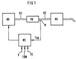
- FIG. 1 schematically shows an internal combustion engine BK which is connected to a pre-catalytic converter VK via a first exhaust pipe R1 and then to a main catalytic converter via a second exhaust pipe R2.
- a measuring point M is provided Immediately downstream of the pre-catalyst VK, a measuring point M is provided via which the exhaust gas temperature behind the pre-catalyst can be measured. The measured value measured at this point is supplied for evaluation together with other measured values to a computer, such as an engine control, in which predetermined procedures are carried out.
- the internal combustion engine is started in a first step S1.
- a subsequent step S2 it is checked whether the switch-on conditions for checking the catalytic converter are fulfilled. This includes the operating conditions, whether the lambda control is active, the secondary air operation is not active, the operating temperature of the internal combustion engine has been reached, the driving speed of the motor vehicle is in a predetermined range and whether the operating conditions before the start of the overrun phase are met. If not, the routine returns to 1. If the switch-on conditions are met, the routine proceeds to a step S3, where the temperature (initial temperature) at the start of the idling phase (LL phase) is measured after the overrun operation. At the same time, a payer is started for the duration of the idle phase.
- step S6 the routine immediately proceeds from S6 to a step S8.
- step S8 the temperature is measured at the end of the idle phase. Furthermore, the difference between the end temperature and the start temperature is determined and all differences are added up. In this step, the total duration of all idle phases is determined.
- step S9 a check counter is incremented.
- step S10 a decision is made as to whether the minimum number of checks has been reached. If not, the routine returns to 1. When the minimum number of checks has been reached, the quotient is formed in a step S11 from the total sum of the differential temperature measurement results to the total sum duration of the measurements in order to obtain a resulting temperature gradient.
- step S12 a decision is made as to whether the resulting temperature gradient is greater than a limit value. If “yes” is decided, the catalytic converter is defective or it no longer meets its minimum requirements, which is indicated in a step S13. If “No” is decided, the routine proceeds to an end step S14.
- the check is generally carried out once per engine run.
Landscapes
- Engineering & Computer Science (AREA)
- Chemical & Material Sciences (AREA)
- Combustion & Propulsion (AREA)
- Mechanical Engineering (AREA)
- General Engineering & Computer Science (AREA)
- Chemical Kinetics & Catalysis (AREA)
- Exhaust Gas After Treatment (AREA)
- Combined Controls Of Internal Combustion Engines (AREA)
Abstract
Description
Die vorliegende Erfindung betrifft ein Verfahren zur Überprüfung der Konvertierungsfahigkeit eines Katalysators nach dem Oberbegriff des Patentanspruchs 1.The present invention relates to a method for checking the convertibility of a catalytic converter according to the preamble of
Zur Umwandlung von schädlichen Bestandteilen in Abgasen von Brennkraftmaschinen werden Katalysatoren eingesetzt, die die in den Abgasen enthaltenen Kohlenwasserstoffe, das Kohlenmonoxid und die Stickstoffe in gesundheitlich unbedenkliche Verbindungen konvertieren. Die Katalysatoren sind im Betrieb harten Bedingungen wie hohen Temperaturen und Erschütterungen ausgesetzt, so daß deren Lebensdauer begrenzt ist. Dies kann während der Lebensdauer eines Kraftfahrzeugs zu einer Verringerung des Konvertierungsgrades des Katalysators führen, was einen Austausch des Katalysators erfordert.To convert harmful components in exhaust gases from internal combustion engines, catalysts are used which convert the hydrocarbons contained in the exhaust gases, the carbon monoxide and the nitrogen into compounds which are harmless to health. The catalysts are exposed to harsh conditions such as high temperatures and vibrations during operation, so that their service life is limited. This can lead to a reduction in the degree of conversion of the catalytic converter during the life of a motor vehicle, which requires replacement of the catalytic converter.
Da die gesetzlichen Abgasvorschriften jedoch während des gesamten Betriebseinsatzes stets erfüllt sein müssen, ist eine Funktionsüberwachung des Katalysators erforderlich. Dabei kann das Überwachungssystem dem Fahrer durch ein optisches oder akustisches Signal anzeigen, wenn der Katalysator nicht mehr einwandfrei arbeitet.However, since the legal exhaust gas regulations must always be met during the entire operational period, the catalytic converter must be monitored for proper functioning. The monitoring system can use an optical or acoustic signal to indicate to the driver when the catalytic converter is no longer working properly.
Durch die DE-PS 26 43 739 ist ein Verfahren zur Überwachung der Aktivität von Katalysatoren für die Abgasreinigung bekannt, bei dem zwei Temperaturfühler vorgesehen sind. Ein Temperaturfühler ist im Katalysator angeordnet, der andere stromaufwärts kurz vor dem Katalysator. Dieses bekannte Verfahren nützt die Tatsache aus, daß bei ordnungsgemäß arbeitendem Katalysator aufgrund von exothermen Reaktionen im Katalysator eine Temperaturerhöhung innerhalb des Systems stattfindet, wobei die am Katalysator gemessene Wärmetönung ein Maß für das Arbeiten des Katalysators ist.From DE-PS 26 43 739 a method for monitoring the activity of catalysts for exhaust gas purification is known, in which two temperature sensors are provided. One temperature sensor is arranged in the catalytic converter, the other upstream just before the catalytic converter. This known method takes advantage of the fact that, when the catalytic converter is working properly, an increase in temperature takes place within the system due to exothermic reactions in the catalytic converter, the temperature of the heat measured on the catalytic converter being a measure of the working of the catalytic converter.
Weiterhin ist durch die DE-OS 41 00 397 ein Verfahren und eine Anordnung zur Überwachung des Konvertierungsgrades eines Katalysators bekannt, bei dem die Temperturdifferenz der Temperaturen vor und hinter dem Katalysator erfaßt und ausgewertet wird, die in einer Schubphase der Brennkraftmaschine bei Erzeugung eines Zündaussetzers und Zuführung einer vorgegebenen Kraftstoff-Luft-Gemischmenge auftreten.Furthermore, from DE-OS 41 00 397 a method and an arrangement for monitoring the degree of conversion of a catalytic converter is known, in which the temperature difference between the temperatures upstream and downstream of the catalytic converter is detected and evaluated, which occurs in an overrun phase of the internal combustion engine when a misfire occurs and Supply of a predetermined amount of air-fuel mixture occur.
Es ist Aufgabe der vorliegenden Erfindung, ein Verfahren zur Überprüfung bzw. Überwachung der Konvertierungsfahigkeit eines Katalysators, insbesondere eines Vorkatalysators vorzustellen, bei dem eine Überprüfung bzw. Überwachung der Funktion des Katalysators möglich ist, ohne in den Katalysator einzugreifen.It is the object of the present invention to present a method for checking or monitoring the convertibility of a catalytic converter, in particular a pre-catalytic converter, in which it is possible to check or monitor the function of the catalytic converter without intervening in the catalytic converter.
Diese Aufgabe wird erfindungsgemäß durch den Patentanspruch 1 gelöst. Vorteilhafte Weiterbildungen sind in den Unteransprüchen gekennzeichnet.This object is achieved by
Aufgrund des Übergangs von einem Betriebspunkt mit höherer Last und Drehzahl über eine Schubphase (Auskühlen durch Sauerstoff) in eine Leerlaufphase (Betriebspunkt mit niedriger Last und Drehzahl) sinkt grundsätzlich die Abgastemperatur. Der Katalysator besitzt bezüglich der Temperatur und Konvertierung eine gewisse Speicherwirkung, so daß dieses Absinken der Temperatur mit einem gewissen Zeitversatz nach dem Katalysator gemessen wird.Due to the transition from an operating point with higher load and speed over an overrun phase (cooling by oxygen) to an idling phase (operating point with low load and speed), the exhaust gas temperature generally drops. The catalyst has a certain storage effect with regard to temperature and conversion, so that this drop in temperature is measured with a certain time lag after the catalyst.
Das unterschiedliche Temperaturverhalten zwischen einem guten und einem defekten Katalysator ist nur sehr gering. Ein signifikanter Unterschied ist nur zu Beginn einer Leerlaufphase festzustellen, die sich direkt an eine Schubphase mit abgeschalteter Einspritzung anschließt, da sich hier durch den in der Schubphase zugeführten Sauerstoff beim Wiedereinsetzen der Einspritzung eine stark exotherme Reaktion einstellt. Weiterhin sollten aufgrund des geringen Unterschieds vor und während der einzelnen Messungen stabile und stets gleiche Bedingungen vorherrschen. Äußerst zuverlässige Kriterien zur Beurteilung der Konvertierungsfähigkeit eines Katalysators lassen sich dadurch erzielen, wenn jeweils mehrere Messungen in einem vorgegebenen Zeitintervall vorgenommen werden und daraus ein Mittelwert gebildet wird, der dann mit einem Grenzwert verglichen wird.The difference in temperature behavior between a good and a defective catalytic converter is only very slight. A significant difference can only be seen at the beginning of an idling phase, which immediately follows a push phase with the injection switched off, since here the oxygen supplied in the push phase results in a strongly exothermic reaction when the injection is restarted. Furthermore, due to the small difference stable and always the same conditions prevail before and during the individual measurements. Extremely reliable criteria for assessing the convertibility of a catalytic converter can be achieved if several measurements are carried out in a given time interval and an average value is formed from this, which is then compared with a limit value.
Das Verfahren ist besonders vorteilhaft auf den ersten Katalysator im Abgastrakt eines Kraftfahrzeugs anwendbar. Dieser kann zweckmäßigerweise durch einen Vorkatalysator gebildet sein, da, wie Untersuchungen gezeigt habe, besonders zuverlässige Meßergebnisse nach dem erfindungsgemäßen Verfahren bei einem Katalysator erzielbar sind, dessen Größe ein gewisses Maß nicht übersteigt.The method is particularly advantageously applicable to the first catalytic converter in the exhaust tract of a motor vehicle. This can expediently be formed by a pre-catalyst, since, as studies have shown, particularly reliable measurement results can be achieved with the catalyst according to the method of the invention, the size of which does not exceed a certain degree.
Da, wie bereits erwähnt, stabile und nahezu gleiche Bedingungen bei den Messungen vorherrschen sowie Störeinflüsse vermieden werden sollen, wird in vorteilhafter Weise die Bestimmung des Temperaturgradienten bei bestimmten Betriebszuständen durchgeführt.Since, as already mentioned, stable and almost identical conditions prevail in the measurements and interference should be avoided, the temperature gradient is advantageously determined in certain operating states.
So soll eine Überprüfung des Katalysators nur dann stattfinden, wenn eine Lambdaregelung aktiv ist. Damit werden Störungen durch Gemischeinflüsse vermieden. Es herrscht eine stabile Verbrennung in der Brennkraftmaschine nach Wiedereinsetzen einer Schubabschaltung vor.The catalyst should only be checked when lambda control is active. This prevents disturbances caused by mixture influences. There is a stable combustion in the internal combustion engine after restarting a fuel cut-off.
Weiter soll eine Überprüfung nur dann vorgenommen werden, wenn keine Sekundärluft in den Katalysator eingeblasen wird. Eine Sekundarlufteinblasung wird zum schnellen Anspringen des Katalysators durchgeführt. Der Katalysator hat zu diesem Zeitpunkt seine Betriebstemperatur noch nicht erreicht. Weiterhin herrscht hier vor dem Katalysator ein mageres Gemisch, so daß der Katalysator nicht arbeitet. Die Überprüfung darf nur durchgeführt werden, wenn sich die Temperatur des Katalysators in dem für die Konvertierung optimalen Temperaturbereich befindet. Die Ermittlung der Katalysator-temperatur kann durch Berechnung über ein in der Motorsteuerung abgelegtes Abgastemperaturmodell erfolgen.Furthermore, a check should only be carried out if no secondary air is blown into the catalytic converter. A secondary air injection is carried out to quickly start the catalytic converter. The catalytic converter has not yet reached its operating temperature at this point. Furthermore, there is a lean mixture in front of the catalyst, so that the catalyst does not work. The check may only be carried out if the temperature of the catalytic converter is within the optimum range for the conversion Temperature range. The catalyst temperature can be determined by calculation using an exhaust gas temperature model stored in the engine control.
Instabile bzw. instationare Verhältnisse liegen auch dann vor, wenn die Brennkraftmaschine noch nicht ihre Betriebstemperatur erreicht hat. Dies läßt sich durch die Kühlwassertemperatur ermitteln, die einen gewissen Mindestwert aufweisen soll, um mit der Überprüfung des Katalysators zu beginnen.Unstable or unsteady conditions also exist if the internal combustion engine has not yet reached its operating temperature. This can be determined by the cooling water temperature, which should have a certain minimum value, in order to start checking the catalytic converter.
Um weiter stabile Verhältnisse zu erhalten und damit eine zuverlässige Messung, soll die Fahrgeschwindigkeit des Kraftfahrzeugs in einem gewissen Bereich liegen. Die Fahrgeschwindigkeit hat ein unterschiedlich starkes Auskühlen bei unterschiedlichen Geschwindigkeiten zur Folge, so daß dieser Einfluß unterdrückt werden soll, um gleiche Verhältnisse bei der Überprüfung zu haben.In order to maintain stable conditions and thus a reliable measurement, the driving speed of the motor vehicle should be in a certain range. The driving speed results in different degrees of cooling at different speeds, so that this influence should be suppressed in order to have the same conditions when checking.
Der Katalysator besitzt in Bezug auf das Konvertierungs- und Temperaturverhalten eine Speicherwirkung. Um nun während der Überprüfung keine Temperaturveränderungen zu messen, die auf Vorgänge vor der Schubphase zurückzuführen sind, ist es zweckmäßig, wenn vor der Schubphase nahezu stationäre Verhältnisse geherrscht haben.The catalyst has a storage effect with regard to the conversion and temperature behavior. In order not to measure any temperature changes during the check which can be attributed to processes before the overrun phase, it is expedient if there were almost stationary conditions before the overrun phase.
Die Erfindung wird nun anhand von zwei Figuren näher erläutert.The invention will now be explained in more detail with reference to two figures.
Es zeigen:
Figur 1 schematisch eine Brennkraftmaschine mit einem Abgastrakt; undFigur 2 ein Flußdiagramm zur Erläuterung des Verfahrens nach der Erfindung.
- Figure 1 shows schematically an internal combustion engine with an exhaust tract; and
- Figure 2 is a flow chart to explain the method according to the invention.
Die Figur 1 zeigt schematisch eine Brennkraftmaschine BK, die über ein erstes Abgasrohr R1 mit einem Vorkatalysator VK und anschließend über ein zweites Abgasrohr R2 mit einem Hauptkatalysator verbunden ist. Stromabwärts hinter dem Vorkatalysator VK ist unmittelbar danach eine Meßstelle M vorgesehen, über die die Abgastemperatur hinter dem Vorkatalysator gemessen werden kann. Der an dieser Stelle gemessene Meßwert wird zur Auswertung gemeinsam mit anderen Meßwerten an einen Rechner wie eine Motorsteuerung geliefert, in der vorbestimmte Prozeduren durchgeführt werden.FIG. 1 schematically shows an internal combustion engine BK which is connected to a pre-catalytic converter VK via a first exhaust pipe R1 and then to a main catalytic converter via a second exhaust pipe R2. Immediately downstream of the pre-catalyst VK, a measuring point M is provided via which the exhaust gas temperature behind the pre-catalyst can be measured. The measured value measured at this point is supplied for evaluation together with other measured values to a computer, such as an engine control, in which predetermined procedures are carried out.
Bei dem in Figur 2 gezeigten Flußdiagramm wird in einem ersten Schritt S1 die Brennkraftmachine gestartet. In einem sich daran anschließenden Schritt S2 wird überprüft, ob die Einschaltebedingungen für die Überprüfung des Katalysators erfüllt sind. Darunter sind die Betriebsbedingungen zu verstehen, ob die Lambdaregelung aktiv ist, der Sekundärluftbetrieb nicht aktiv ist, die Betriebstemperatur der Brennkraftmaschine erreicht ist, die Fahrgeschwindigkeit des Kraftfahrzeugs in einem vorgegebenen Bereich sich befindet und ob die betriebstationären Bedingungen vor dem Eintritt in die Schubphase erfüllt sind. Ist dies nicht der Fall, kehrt die Routine zu 1 zurück. Sind die Einschaltebedingungen erfüllt, so schreitet die Routine zu einem Schritt S3, wo die Temperatur (Anfangstemperatur) zu Beginn der Leerlaufphase (LL-Phase) nach dem Schubbetrieb gemessen wird. Gleichzeitig wird ein Zahler für die Dauer der Leerlaufphase gestartet. In einem sich anschließenden Schritt S4 wird entschieden, ob die Dauer der Leerlaufphase größer als eine Minimaldauer ist. Wenn "Nein" entschieden wird, schreitet die Routine zu einem Schritt S5, wo überprüft wird, ob die Bedingung für den Leerlauf noch erfüllt ist. Wenn "Ja" entschieden wird, kehrt die Routine zu 2 zurück. Wenn "Nein" entschieden wird, kehrt die Routine zum Anfang der Routine , d.h. zu 1 zurück. Ist die Dauer der Leerlaufphase größer als die Minimaldauer, so schreitet die Routine zu einem Entscheidungsschritt S6 weiter, wo entschieden wird, ob die Dauer der Leerlaufphase gleich der Maximaldauer ist. Wenn bei S6 "Nein" entschieden wird, schreitet die Routine zu einem Schritt S7, wo entschieden wird, ob die Bedingung für den Leerlauf noch erfüllt ist. Wenn bei S7 "Ja" entschieden wird, kehrt die Routine zu 3 zurück. Wenn "Nein" entschieden wird, schreitet die Routine zu einem Schritt S8.In the flowchart shown in FIG. 2, the internal combustion engine is started in a first step S1. In a subsequent step S2, it is checked whether the switch-on conditions for checking the catalytic converter are fulfilled. This includes the operating conditions, whether the lambda control is active, the secondary air operation is not active, the operating temperature of the internal combustion engine has been reached, the driving speed of the motor vehicle is in a predetermined range and whether the operating conditions before the start of the overrun phase are met. If not, the routine returns to 1. If the switch-on conditions are met, the routine proceeds to a step S3, where the temperature (initial temperature) at the start of the idling phase (LL phase) is measured after the overrun operation. At the same time, a payer is started for the duration of the idle phase. In a subsequent step S4, a decision is made as to whether the duration of the idle phase is greater than a minimum duration. If "No" is decided, the routine proceeds to step S5, where it is checked whether the condition for idling is still satisfied. If "yes" is decided, the routine returns to 2. If "No" is decided, the routine returns to the beginning of the routine, that is, to 1. If the duration of the idle phase is greater than the minimum duration, the routine proceeds to a decision step S6, where it is decided whether the duration of the idle phase is equal to the maximum duration. If "No" is decided at S6, the routine proceeds to step S7, where it is decided whether the condition for idling is still satisfied. If "Yes" is decided in S7, the routine returns to 3. If "No" is decided, the routine proceeds to step S8.
Wenn bei Schritt S6 "Ja" entschieden wird, schreitet die Routine unmittelbar von S6 zu einem Schritt S8. In diesem Schritt S8 wird die Temperatur am Ende der Leerlaufphase gemessen. Weiter wird die Differenz zwischen der Endtemperatur und der Anfangstemperatur ermittelt und alle Differenzen werden aufsummiert. In diesem Schritt wird die Gesamtdauer aller Leerlaufphasen ermittelt. Im Schritt S9 wird ein Überprüfungszähler inkrementiert. Im sich anschließenden Schritt S10 wird entschieden, ob die Mindestanzahl von Überprüfungen erreicht ist. Wenn dies nicht der Fall ist, kehrt die Routine zu 1 zurück. Wenn die Mindestanzahl von Überprüfungen erreicht ist, wird in einem Schritt S11 der Quotient aus der Gesamtsumme der Differenz- Temperaturmeßergebnisse zur Gesamtsummendauer der Messungen gebildet, um einen resutierenden Temperaturgradienten zu erhalten. Im sich daran anschließenden Schritt S12 wird entschieden, ob der resultierende Temperaturgradient großer als ein Grenzwert ist. Wenn "Ja" entschieden wird, ist der Katalysator defekt bzw. er erfüllt nicht mehr seine Mindestanforderungen, was in einem Schritt S13 angezeigt wird. Wenn "Nein" entschieden wird, schreitet die Routine zu einem Endeschritt S14 weiter.If "Yes" is decided in step S6, the routine immediately proceeds from S6 to a step S8. In this step S8, the temperature is measured at the end of the idle phase. Furthermore, the difference between the end temperature and the start temperature is determined and all differences are added up. In this step, the total duration of all idle phases is determined. In step S9, a check counter is incremented. In the subsequent step S10, a decision is made as to whether the minimum number of checks has been reached. If not, the routine returns to 1. When the minimum number of checks has been reached, the quotient is formed in a step S11 from the total sum of the differential temperature measurement results to the total sum duration of the measurements in order to obtain a resulting temperature gradient. In the subsequent step S12, a decision is made as to whether the resulting temperature gradient is greater than a limit value. If "yes" is decided, the catalytic converter is defective or it no longer meets its minimum requirements, which is indicated in a step S13. If "No" is decided, the routine proceeds to an end step S14.
Die Überprüfung wird im allgemeinen einmal pro Motorlauf durchgeführt.The check is generally carried out once per engine run.
Claims (5)
- Method for checking the conversion capability of a catalyzer arranged in the exhaust duct in motor vehicles with internal combustion engines by means of a temperature measurement in the exhaust duct immediately downstream of the catalyzer, in particular for checking a first catalyzer, characterized by the following steps:a) measurement of the temperature in each case at the beginning and at the end of a predetermined number of idling phases as reference phases, following an overrun phase and given predetermined operating states of the motor vehicle and/or of the internal combustion engine;b) formation of the difference of the temperature measurements at the beginning and end of each reference phase;c) formation of the total sum of all the differences and a time sum from the durations of the reference phases;d) formation of an average temperature gradient from the total sum and the time sum;e) comparison of the average temperature gradient with a predetermined limiting value; andf) recognition that the catalyzer is defective if the average temperature quotient exceeds the limiting value.
- Method according to Claim 1, characterized in that the following operating states, or at least some of them, are present:a) a lambda closed-loop control system is active;b) secondary air operation is not active;c) the operating temperature of the internal combustion engine is in the correct range;d) the vehicle speed of the motor vehicle is lower than a maximum value upon entry into the idling phase;e) conditions of steady-state operation must hold for a predetermined period before entry into the overrun phase; andf) the calculated catalyzer equivalent temperature is in a predetermined temperature range.
- Method according to Claim 1, characterized in that the idling phase in each case follows an overrun phase with the injection switched off.
- Method according to Claim 1, characterized in that the operating states are evaluated in a computer and the beginning of checking is determined by the computer.
- Method according to Claim 4, characterized in that the computer is formed by an existing engine controller.
Priority Applications (1)
| Application Number | Priority Date | Filing Date | Title |
|---|---|---|---|
| EP95905098A EP0736136B1 (en) | 1993-12-21 | 1994-12-21 | Method for testing the convertability of a catalytic converter |
Applications Claiming Priority (4)
| Application Number | Priority Date | Filing Date | Title |
|---|---|---|---|
| EP93120626 | 1993-12-21 | ||
| EP93120626 | 1993-12-21 | ||
| EP95905098A EP0736136B1 (en) | 1993-12-21 | 1994-12-21 | Method for testing the convertability of a catalytic converter |
| PCT/EP1994/004262 WO1995017588A1 (en) | 1993-12-21 | 1994-12-21 | Method for testing the convertability of a catalytic converter |
Publications (2)
| Publication Number | Publication Date |
|---|---|
| EP0736136A1 EP0736136A1 (en) | 1996-10-09 |
| EP0736136B1 true EP0736136B1 (en) | 1997-09-10 |
Family
ID=8213513
Family Applications (1)
| Application Number | Title | Priority Date | Filing Date |
|---|---|---|---|
| EP95905098A Expired - Lifetime EP0736136B1 (en) | 1993-12-21 | 1994-12-21 | Method for testing the convertability of a catalytic converter |
Country Status (5)
| Country | Link |
|---|---|
| US (1) | US5732549A (en) |
| EP (1) | EP0736136B1 (en) |
| JP (1) | JPH09506949A (en) |
| DE (1) | DE59404052D1 (en) |
| WO (1) | WO1995017588A1 (en) |
Families Citing this family (18)
| Publication number | Priority date | Publication date | Assignee | Title |
|---|---|---|---|---|
| SE505235C2 (en) * | 1995-06-07 | 1997-07-21 | Volvo Ab | Method and apparatus for determining the oxygen buffer capacity of a catalytic exhaust cleaner |
| JP3135499B2 (en) * | 1995-10-25 | 2001-02-13 | トヨタ自動車株式会社 | Catalyst deterioration judgment device |
| EP0786586A3 (en) * | 1996-06-21 | 1997-10-29 | Toyota Motor Co Ltd | Device for evaluating catalyst performance deterioration |
| US5896743A (en) * | 1997-06-24 | 1999-04-27 | Heraeus Electro-Nite International N.V. | Catalyst monitor utilizing a lifetime temperature profile for determining efficiency |
| DE19726791A1 (en) * | 1997-06-24 | 1999-01-07 | Volkswagen Ag | Method for monitoring the conversion rate of an exhaust gas catalytic converter for an internal combustion engine |
| US7886523B1 (en) | 1998-08-24 | 2011-02-15 | Legare Joseph E | Control methods for improved catalytic converter efficiency and diagnosis |
| US7707821B1 (en) | 1998-08-24 | 2010-05-04 | Legare Joseph E | Control methods for improved catalytic converter efficiency and diagnosis |
| US6651422B1 (en) | 1998-08-24 | 2003-11-25 | Legare Joseph E. | Catalyst efficiency detection and heating method using cyclic fuel control |
| SE522219C2 (en) | 2000-05-10 | 2004-01-27 | Ford Global Tech Llc | Motor vehicle comprising a catalytically coated cooler in a motor vehicle |
| US6695473B2 (en) * | 2002-05-30 | 2004-02-24 | Ford Global Technologies, Llc | Diagnostic system and method for a motor vehicle |
| DE10303911B4 (en) * | 2003-01-31 | 2005-02-10 | Siemens Ag | Method for monitoring the starting behavior of an exhaust gas catalytic converter system |
| US7349794B2 (en) * | 2003-09-03 | 2008-03-25 | Malone Specialty, Inc. | Engine protection system |
| US7184878B2 (en) * | 2003-09-03 | 2007-02-27 | Malone Specialty, Inc. | Engine protection system |
| JP4238788B2 (en) * | 2004-06-21 | 2009-03-18 | トヨタ自動車株式会社 | Particulate filter abnormality judgment method |
| DE102004050769A1 (en) * | 2004-10-16 | 2006-04-20 | Robert Bosch Gmbh | A method of determining information about a device exposed to temperature |
| FR2877392A1 (en) * | 2004-11-02 | 2006-05-05 | Renault Sas | DEVICE FOR CONTROLLING THE OPERATING STATE OF A CATALYTIC CONVERTER OF AN EXHAUST LINE OF AN INTERNAL COMBUSTION ENGINE AND AN ENGINE COMPRISING SUCH A DEVICE |
| ATE448395T1 (en) | 2007-08-31 | 2009-11-15 | Umicore Ag & Co Kg | METHOD FOR CHECKING THE AGING CONDITION OF A CATALYST ON BOARD A VEHICLE |
| US8850804B2 (en) * | 2013-02-15 | 2014-10-07 | GM Global Technology Operations LLC | Dual path SAIR for dual plane integrated exhaust manifolds |
Family Cites Families (9)
| Publication number | Priority date | Publication date | Assignee | Title |
|---|---|---|---|---|
| DE2643739C2 (en) * | 1976-09-29 | 1986-03-13 | Robert Bosch Gmbh, 7000 Stuttgart | Method for monitoring the activity of catalytic converters for exhaust gas purification |
| JP2518696B2 (en) * | 1989-07-26 | 1996-07-24 | 日産自動車株式会社 | Diagnostic device for exhaust purification system of internal combustion engine |
| DE4100397C2 (en) * | 1990-02-10 | 1999-08-05 | Volkswagen Ag | Method and arrangement for monitoring the degree of conversion of a catalytic converter |
| JPH0460106A (en) * | 1990-06-29 | 1992-02-26 | Mazda Motor Corp | Control device of engine |
| DE4027207A1 (en) * | 1990-08-28 | 1992-03-05 | Emitec Emissionstechnologie | MONITORING THE CATALYTIC ACTIVITY OF A CATALYST IN THE EXHAUST SYSTEM OF AN INTERNAL COMBUSTION ENGINE |
| JP2724387B2 (en) * | 1990-08-28 | 1998-03-09 | 本田技研工業株式会社 | Failure detection method for exhaust air supply system for internal combustion engine |
| DE4039762A1 (en) * | 1990-12-13 | 1992-06-17 | Bosch Gmbh Robert | METHOD AND DEVICE FOR CHECKING THE AGING STATE OF A CATALYST |
| DE4302779C2 (en) * | 1993-02-02 | 1995-10-05 | Porsche Ag | Method for checking the functionality of exhaust gas catalysts used in the exhaust gas system of motor vehicles equipped with an internal combustion engine |
| US5363646A (en) * | 1993-09-27 | 1994-11-15 | Ford Motor Company | Engine air/fuel control system with catalytic converter monitoring |
-
1994
- 1994-12-21 JP JP7517193A patent/JPH09506949A/en active Pending
- 1994-12-21 DE DE59404052T patent/DE59404052D1/en not_active Expired - Fee Related
- 1994-12-21 WO PCT/EP1994/004262 patent/WO1995017588A1/en active IP Right Grant
- 1994-12-21 EP EP95905098A patent/EP0736136B1/en not_active Expired - Lifetime
-
1996
- 1996-06-20 US US08/666,969 patent/US5732549A/en not_active Expired - Fee Related
Also Published As
| Publication number | Publication date |
|---|---|
| EP0736136A1 (en) | 1996-10-09 |
| WO1995017588A1 (en) | 1995-06-29 |
| DE59404052D1 (en) | 1997-10-16 |
| JPH09506949A (en) | 1997-07-08 |
| US5732549A (en) | 1998-03-31 |
Similar Documents
| Publication | Publication Date | Title |
|---|---|---|
| EP0736136B1 (en) | Method for testing the convertability of a catalytic converter | |
| EP0689640B1 (en) | Process for checking the conversion capability of a catalyst | |
| EP1373693B2 (en) | Method and device for monitoring an exhaust gas treatment system | |
| EP1426575B1 (en) | Method and apparatus for monitoring an exhaust gas after-treatment system | |
| DE4302779C2 (en) | Method for checking the functionality of exhaust gas catalysts used in the exhaust gas system of motor vehicles equipped with an internal combustion engine | |
| EP1084331B1 (en) | Method and device to monitor the functioning of a catalyst in an internal combustion engine | |
| DE10319983B3 (en) | Device for regulating the lambda value in an I.C. engine with a catalyst arranged in the exhaust gas pipe, comprises a nitrogen oxides sensor arranged after a partial volume of the catalyst or downstream of the catalyst | |
| EP1192340B1 (en) | Method for verifying a catalytic exhaust box of an internal combustion engine | |
| WO2002073146A1 (en) | Method and device for monitoring a sensor | |
| EP1097299A1 (en) | METHOD FOR CHECKING THE EFFICIENCY OF AN NOx ACCUMULATION CATALYST | |
| DE102006000036A1 (en) | Emission control system of an internal combustion engine | |
| WO2001021951A1 (en) | METHOD FOR MONITORING THE FUNCTIONING OF AN NOx SENSOR ARRANGED IN AN EXHAUST GAS CHANNEL OF AN INTERNAL COMBUSTION ENGINE | |
| DE69635917T2 (en) | Detection device of catalyst deterioration of an internal combustion engine | |
| DE102010039013A1 (en) | Method and apparatus for regeneration of a particulate filter | |
| DE102007000001A1 (en) | Method for detecting excessive combustion | |
| DE10001133A1 (en) | Device for controlling the air-fuel ratio in an I.C. engine comprises a nitrogen oxides catalyst, an air-fuel controller, and estimators for estimating the amount of nitrogen oxides exhaust gas released and the nitrogen oxides concentration | |
| EP0530655B1 (en) | Method and apparatus for controlling an internal combustion engine and testing its catalytic converter | |
| EP1052385A2 (en) | Method of diagnosing a catalyst having hydrocarbon oxidizing properties | |
| EP0626506B1 (en) | Methode for monitoring catalyst efficiency | |
| DE102004051747A1 (en) | Internal-combustion engine operation comprises determining nitrogen oxide concentration, fill level, and operating temperature of the nitrogen oxide accumulator catalyst and correcting a signal off set | |
| DE10234340B4 (en) | Method for determining the loading state of a particle filter of an internal combustion engine | |
| DE102006011894B4 (en) | Method for correcting a signal provided by a lambda sensor | |
| DE19828928C2 (en) | Method for monitoring the exhaust gas purification system of an internal combustion engine | |
| EP1138898B1 (en) | Method and device for purification of exhaust gases | |
| WO2007087920A1 (en) | Method for operating an exhaust-gas catalytic converter of an internal combustion engine |
Legal Events
| Date | Code | Title | Description |
|---|---|---|---|
| PUAI | Public reference made under article 153(3) epc to a published international application that has entered the european phase |
Free format text: ORIGINAL CODE: 0009012 |
|
| AK | Designated contracting states |
Kind code of ref document: A1 Designated state(s): DE FR GB |
|
| 17P | Request for examination filed |
Effective date: 19960306 |
|
| GRAG | Despatch of communication of intention to grant |
Free format text: ORIGINAL CODE: EPIDOS AGRA |
|
| 17Q | First examination report despatched |
Effective date: 19961120 |
|
| GRAH | Despatch of communication of intention to grant a patent |
Free format text: ORIGINAL CODE: EPIDOS IGRA |
|
| GRAH | Despatch of communication of intention to grant a patent |
Free format text: ORIGINAL CODE: EPIDOS IGRA |
|
| GRAA | (expected) grant |
Free format text: ORIGINAL CODE: 0009210 |
|
| AK | Designated contracting states |
Kind code of ref document: B1 Designated state(s): DE FR GB |
|
| REF | Corresponds to: |
Ref document number: 59404052 Country of ref document: DE Date of ref document: 19971016 |
|
| ET | Fr: translation filed | ||
| GBT | Gb: translation of ep patent filed (gb section 77(6)(a)/1977) |
Effective date: 19971113 |
|
| PLBE | No opposition filed within time limit |
Free format text: ORIGINAL CODE: 0009261 |
|
| STAA | Information on the status of an ep patent application or granted ep patent |
Free format text: STATUS: NO OPPOSITION FILED WITHIN TIME LIMIT |
|
| 26N | No opposition filed | ||
| PGFP | Annual fee paid to national office [announced via postgrant information from national office to epo] |
Ref country code: DE Payment date: 19990219 Year of fee payment: 5 |
|
| PGFP | Annual fee paid to national office [announced via postgrant information from national office to epo] |
Ref country code: GB Payment date: 19991214 Year of fee payment: 6 |
|
| PGFP | Annual fee paid to national office [announced via postgrant information from national office to epo] |
Ref country code: FR Payment date: 19991221 Year of fee payment: 6 |
|
| PG25 | Lapsed in a contracting state [announced via postgrant information from national office to epo] |
Ref country code: DE Free format text: LAPSE BECAUSE OF NON-PAYMENT OF DUE FEES Effective date: 20001003 |
|
| PG25 | Lapsed in a contracting state [announced via postgrant information from national office to epo] |
Ref country code: GB Free format text: LAPSE BECAUSE OF NON-PAYMENT OF DUE FEES Effective date: 20001221 |
|
| GBPC | Gb: european patent ceased through non-payment of renewal fee |
Effective date: 20001221 |
|
| PG25 | Lapsed in a contracting state [announced via postgrant information from national office to epo] |
Ref country code: FR Free format text: LAPSE BECAUSE OF NON-PAYMENT OF DUE FEES Effective date: 20010831 |
|
| REG | Reference to a national code |
Ref country code: FR Ref legal event code: ST |