EP0735616A2 - Electric connector, especially for circuit boards - Google Patents
Electric connector, especially for circuit boards Download PDFInfo
- Publication number
- EP0735616A2 EP0735616A2 EP96105169A EP96105169A EP0735616A2 EP 0735616 A2 EP0735616 A2 EP 0735616A2 EP 96105169 A EP96105169 A EP 96105169A EP 96105169 A EP96105169 A EP 96105169A EP 0735616 A2 EP0735616 A2 EP 0735616A2
- Authority
- EP
- European Patent Office
- Prior art keywords
- spring
- contact
- connector according
- connector
- conductor
- Prior art date
- Legal status (The legal status is an assumption and is not a legal conclusion. Google has not performed a legal analysis and makes no representation as to the accuracy of the status listed.)
- Withdrawn
Links
- 239000002184 metal Substances 0.000 claims abstract description 10
- 239000004020 conductor Substances 0.000 claims description 91
- 238000005452 bending Methods 0.000 claims description 31
- 238000003780 insertion Methods 0.000 claims description 24
- 230000037431 insertion Effects 0.000 claims description 24
- 241000722921 Tulipa gesneriana Species 0.000 claims description 17
- 230000001154 acute effect Effects 0.000 claims description 3
- 238000009413 insulation Methods 0.000 abstract description 3
- 238000012360 testing method Methods 0.000 description 11
- 238000004519 manufacturing process Methods 0.000 description 5
- 238000013461 design Methods 0.000 description 4
- 238000000034 method Methods 0.000 description 3
- 230000005405 multipole Effects 0.000 description 3
- 238000011161 development Methods 0.000 description 2
- 230000000694 effects Effects 0.000 description 2
- 238000005516 engineering process Methods 0.000 description 2
- 239000000463 material Substances 0.000 description 2
- 230000013011 mating Effects 0.000 description 2
- 230000000295 complement effect Effects 0.000 description 1
- 238000010276 construction Methods 0.000 description 1
- 230000006735 deficit Effects 0.000 description 1
- 230000008030 elimination Effects 0.000 description 1
- 238000003379 elimination reaction Methods 0.000 description 1
- 239000004744 fabric Substances 0.000 description 1
- 210000003746 feather Anatomy 0.000 description 1
- 210000003128 head Anatomy 0.000 description 1
- 238000009434 installation Methods 0.000 description 1
- 238000012423 maintenance Methods 0.000 description 1
- 238000012545 processing Methods 0.000 description 1
- 230000008439 repair process Effects 0.000 description 1
- 229910000679 solder Inorganic materials 0.000 description 1
- 238000005476 soldering Methods 0.000 description 1
Images


Classifications
-
- H—ELECTRICITY
- H01—ELECTRIC ELEMENTS
- H01R—ELECTRICALLY-CONDUCTIVE CONNECTIONS; STRUCTURAL ASSOCIATIONS OF A PLURALITY OF MUTUALLY-INSULATED ELECTRICAL CONNECTING ELEMENTS; COUPLING DEVICES; CURRENT COLLECTORS
- H01R12/00—Structural associations of a plurality of mutually-insulated electrical connecting elements, specially adapted for printed circuits, e.g. printed circuit boards [PCB], flat or ribbon cables, or like generally planar structures, e.g. terminal strips, terminal blocks; Coupling devices specially adapted for printed circuits, flat or ribbon cables, or like generally planar structures; Terminals specially adapted for contact with, or insertion into, printed circuits, flat or ribbon cables, or like generally planar structures
- H01R12/70—Coupling devices
- H01R12/77—Coupling devices for flexible printed circuits, flat or ribbon cables or like structures
- H01R12/79—Coupling devices for flexible printed circuits, flat or ribbon cables or like structures connecting to rigid printed circuits or like structures
-
- H—ELECTRICITY
- H01—ELECTRIC ELEMENTS
- H01R—ELECTRICALLY-CONDUCTIVE CONNECTIONS; STRUCTURAL ASSOCIATIONS OF A PLURALITY OF MUTUALLY-INSULATED ELECTRICAL CONNECTING ELEMENTS; COUPLING DEVICES; CURRENT COLLECTORS
- H01R4/00—Electrically-conductive connections between two or more conductive members in direct contact, i.e. touching one another; Means for effecting or maintaining such contact; Electrically-conductive connections having two or more spaced connecting locations for conductors and using contact members penetrating insulation
- H01R4/28—Clamped connections, spring connections
- H01R4/48—Clamped connections, spring connections utilising a spring, clip, or other resilient member
- H01R4/4809—Clamped connections, spring connections utilising a spring, clip, or other resilient member using a leaf spring to bias the conductor toward the busbar
- H01R4/48185—Clamped connections, spring connections utilising a spring, clip, or other resilient member using a leaf spring to bias the conductor toward the busbar adapted for axial insertion of a wire end
- H01R4/4819—Clamped connections, spring connections utilising a spring, clip, or other resilient member using a leaf spring to bias the conductor toward the busbar adapted for axial insertion of a wire end the spring shape allowing insertion of the conductor end when the spring is unbiased
- H01R4/4821—Single-blade spring
-
- H—ELECTRICITY
- H01—ELECTRIC ELEMENTS
- H01R—ELECTRICALLY-CONDUCTIVE CONNECTIONS; STRUCTURAL ASSOCIATIONS OF A PLURALITY OF MUTUALLY-INSULATED ELECTRICAL CONNECTING ELEMENTS; COUPLING DEVICES; CURRENT COLLECTORS
- H01R12/00—Structural associations of a plurality of mutually-insulated electrical connecting elements, specially adapted for printed circuits, e.g. printed circuit boards [PCB], flat or ribbon cables, or like generally planar structures, e.g. terminal strips, terminal blocks; Coupling devices specially adapted for printed circuits, flat or ribbon cables, or like generally planar structures; Terminals specially adapted for contact with, or insertion into, printed circuits, flat or ribbon cables, or like generally planar structures
- H01R12/70—Coupling devices
- H01R12/71—Coupling devices for rigid printing circuits or like structures
- H01R12/72—Coupling devices for rigid printing circuits or like structures coupling with the edge of the rigid printed circuits or like structures
- H01R12/721—Coupling devices for rigid printing circuits or like structures coupling with the edge of the rigid printed circuits or like structures cooperating directly with the edge of the rigid printed circuits
-
- H—ELECTRICITY
- H01—ELECTRIC ELEMENTS
- H01R—ELECTRICALLY-CONDUCTIVE CONNECTIONS; STRUCTURAL ASSOCIATIONS OF A PLURALITY OF MUTUALLY-INSULATED ELECTRICAL CONNECTING ELEMENTS; COUPLING DEVICES; CURRENT COLLECTORS
- H01R4/00—Electrically-conductive connections between two or more conductive members in direct contact, i.e. touching one another; Means for effecting or maintaining such contact; Electrically-conductive connections having two or more spaced connecting locations for conductors and using contact members penetrating insulation
- H01R4/28—Clamped connections, spring connections
- H01R4/48—Clamped connections, spring connections utilising a spring, clip, or other resilient member
- H01R4/4809—Clamped connections, spring connections utilising a spring, clip, or other resilient member using a leaf spring to bias the conductor toward the busbar
- H01R4/484—Spring housing details
- H01R4/4842—Spring housing details the spring housing being provided with a single opening for insertion of a spring-activating tool
-
- H—ELECTRICITY
- H01—ELECTRIC ELEMENTS
- H01R—ELECTRICALLY-CONDUCTIVE CONNECTIONS; STRUCTURAL ASSOCIATIONS OF A PLURALITY OF MUTUALLY-INSULATED ELECTRICAL CONNECTING ELEMENTS; COUPLING DEVICES; CURRENT COLLECTORS
- H01R4/00—Electrically-conductive connections between two or more conductive members in direct contact, i.e. touching one another; Means for effecting or maintaining such contact; Electrically-conductive connections having two or more spaced connecting locations for conductors and using contact members penetrating insulation
- H01R4/28—Clamped connections, spring connections
- H01R4/48—Clamped connections, spring connections utilising a spring, clip, or other resilient member
- H01R4/4809—Clamped connections, spring connections utilising a spring, clip, or other resilient member using a leaf spring to bias the conductor toward the busbar
- H01R4/4846—Busbar details
- H01R4/485—Single busbar common to multiple springs
Definitions
- the invention relates to an electrical connector with the features of the preamble of claim 1.
- both the printed circuit board and an electrical conductor are electrically connected by means of plug-in assembly to the contact spring lying in the insulating housing of the connector.
- both the circuit board-connector connection and the connector-conductor connection are realized by a direct plug connection.
- a disadvantage of the known connector is the complex design of the contact spring.
- connection end causes the metal sleeve to be pressurized when the conductor is inserted. The connection end then returns to its starting position and engages behind the metal sleeve for locking the conductor in the insulating housing.
- the invention has for its object to simplify the plug-in assembly of a connector of the type mentioned and to improve its operational safety. This object is achieved by the combination of features of claim 1.
- connection end of the contact spring acts directly on the conductor inserted into the insulating housing with spring force for the electrical connection and at the same time for the clamp fixation of the conductor on the plug connector. Due to their spring elasticity, the connection end adapts to different outer contours of the conductor or the conductor end, without any loss of electrical connection reliability of the conductor in the insulating housing of the connector. Different types of conductors can therefore be connected to the connector at the connector according to the invention by a simple plug-in process. This supports the universal applicability of the connector according to the invention. For example, the stripped conductor end of a conventional conductor can also be connected to the connector.
- connection end can be preprogrammed to a certain extent by appropriate processing of the contact spring and / or by the spring constant of the selected spring material.
- connection end of the contact spring can be adapted even better to different conductor cross sections. According to the invention, it is therefore possible, without any design changes to the insulating housing, that contact springs of identical design have connection ends with different spring force if conductors with different line cross sections are to be connected to a multipole connector.
- connection end is designed in the manner of a barb and additionally acts on the conductor with a holding force which is effective approximately in the insertion direction and which prevents the conductor from being pulled out of the insulating housing of the plug connector in an undesired manner.
- this barb is technically simply formed by an angled portion of the contact spring, whereby the connection end is also constructed to save space.
- the conductor automatically bends the connection end against the spring force when it is inserted into the insulating housing. When the conductor is fully inserted, the connection end also springs back automatically and clamps the conductor with its spring force.
- the contact spring is slotted longitudinally at the connection end, so that two mutually independent conductors can be connected to the same contact spring per connection pole.
- the conductors have a small cross section, e.g. is the case in telecommunications.
- two conductors with the same pole can advantageously be mechanically and electrically connected.
- connection end is limited during the manufacture or release of the clamp fixation. This ensures that the connection end acted upon from the outside by the inserted conductor or an assembly tool has a constant spring force over a long operating time.
- the measure according to claim 5 supports the mechanically stable support of the externally loaded and thereby pivoted connection end on the stop tab.
- Claims 6 and 7 enable a mechanically reliable hold and fit of the plug connector, in particular that plugged onto a printed circuit board Connector. According to claim 7, the mechanical and electrical contact pressure of the contact spring on an electrical contact point, in particular on the contact field of a printed circuit board, is further improved.
- Claim 8 supports the positional securing of the entire contact spring within the insulating housing of the connector.
- the contact spring is simply inserted into the insulating housing from an assembly point of view and automatically engages there.
- a catch element which is preferably connected in one piece to the contact spring and which interacts with a fixing lug formed in the insulating housing, serves as the locking means. This prevents the contact spring from being accidentally pulled out of the insulating housing against the direction of insertion.
- a deliberate release of the latched contact spring can be provided by means of suitable measures and / or by means of assembly tools which engage in the insulating housing.
- the rear engagement part for securing the position of the contact spring is arranged in a mechanically stable and space-saving manner on the spring base body of the contact spring.
- Claim 10 supports the manufacture and use of the contact spring as an inexpensive mass article.
- Claim 11 favors a space-saving structure of the contact spring. This advantageously further miniaturizes the entire connector.
- Claim 12 favors the division of the contact spring into two mutually independent lever arms.
- the circuit board and the conductor can therefore advantageously be electrically contacted independently of one another with the contact spring, without there being any impairments in the clamping fixation or the electrical contacting by the respective other lever arm.
- the measure according to claim 13 makes it easier for the fitter to insert a conductor into the connector in accordance with the assembly.
- the measure according to claim 14 creates a continuous development of the plug-in assembly of the connector.
- one or more latching hooks are arranged on the insulating housing, which latch in a springy manner. In cooperation with a circuit board, these latching hooks engage in corresponding locking openings in the circuit board. In this way, the connector on the circuit board is securely locked and further stabilized against unwanted changes in position.
- the contact spring itself accomplishes the clamping fixation or plug-in assembly of a conductor and an element to be contacted. Since the contact spring is made of electrically conductive metal, it has consistently good thermal and mechanical properties over a long period of operation. As a result, standardization requirements for the clamp fixation or plug-in assembly can be easily met. In addition, due to the elimination of thermal / mechanical loads, the insulating housing can be produced from a comparatively inferior and therefore inexpensive insulating plastic.
- the connector can be inserted in different relative positions, in particular both horizontally and vertically. This allows the connector to be space-savingly adapted to different space conditions or required relative positions.
- Claim 18 proposes a particularly simple and mechanically stable plug connection between the contact spring and an element to be contacted.
- This element is in particular a contact pin of the printed circuit board, which can be positioned differently on the printed circuit board.
- This " indirect" plug-in assembly between contact spring and printed circuit board results compared to plugging the connector directly onto the edge of the PCB ( direct “plug-in assembly) more variable positioning options for the connector on the circuit board.
- Claim 19 additionally stabilizes the plug-in assembly.
- the diametrical slot allows the tulip contact to be adapted in the manner of a spring contact to differently dimensioned contact pins or elements to be contacted.
- Claim 20 creates a particularly stable configuration of the contact spring, the components projecting beyond the spring base body being an integral part of the contact spring.
- Claim 23 proposes a stable metal abutment for the spring leg-like connection end. This improves the clamping force exerted on the connected conductor.
- the measure according to claim 24 makes it easier for the fitter to insert a conductor into the connector in accordance with the assembly.
- each pole of the connector is preferably identical, so that structurally identical contact springs can also be used in the insulating housing.
- the number of components to be stored for the implementation of all embodiments of the connector therefore remains low. Due to the identical design of the connection poles of the insulating housing, similar molds can be used for the cost-effective production of the plug connectors.
- the multi-pin connector is a more compact and mechanically stable unit. At the same time, even on a multi-pole connector with a large number of poles, the connection of many conductors remains clear and easy to install.
- the electrical connector 1 has an insulating housing 2 and, depending on the number of poles, one or more contact springs 3 arranged in the insulating housing 2 (FIG. 1, FIG. 2). 5, the plug connector 1 is plugged onto a printed circuit board 5 in the plugging direction 4 and provided with an inserted conductor 11.
- the circuit board 5 contains a plurality of conductor tracks 6, each of which is assigned an electrical contact field 7 at the end.
- a contact end 8 of the contact spring 3 is under mechanical prestress, i.e. under spring tension on a contact field 7 of the printed circuit board 5 (FIG. 5).
- the electrical connection between the contact spring 3 and the associated conductor track 6 is established by the bias.
- the contact spring 3 has a connection end 10 facing away from the contact end 8 in the spring longitudinal direction 9. (Fig.5).
- the connection end 10 can be electrically connected to a conductor 11 assigned to the contact spring 3.
- the connection end 10 acts directly on the conductor 11 with spring force. In this way, the electrical connection and at the same time a clamping fixation of the conductor 11 to the connector 1 is realized. 5 that the connection end 10 presses the conductor 11 or its stripped conductor end 12 directly against an inner wall of the insulating housing 2. This provides a good mechanical hold for the stripped end 12 in the insulating housing 2.
- connection end 10 acts upon the conductor 11, which is inserted into the insulating housing 2 in the insertion direction 13, in the manner of a barb. This barb prevents undesired removal of the conductor 11 against the insertion direction 13.
- the terminal end 10 is directed as an end section with the contact spring 3 towards the spring base body 15, i.e. bent in the bending direction 15 (Fig. 7).
- the connection end 10 and the spring base body 14 form an acute angle ⁇ of approximately 40 ° -60 °.
- connection end 10 In the assembled state of the contact spring 3, the conductor end 12 inserted into the insulating housing 2 is clamped by the free end 16 of the connection end 10 which points approximately in the direction of insertion 13, as a result of which the barb effect of the connection end 10 is produced.
- connection end 10 has a longitudinal slot 17 running in the longitudinal direction 9 of the spring. This longitudinal slot 17 extends from the free end 16 approximately to the arcuate bending point 18 of the connection end 10. Through the longitudinal slot 17, the connection end 10 is divided in two in the transverse direction 19 arranged at right angles to the spring longitudinal direction 9 to form two connection contacts 20, 21 for each conductor 11.
- the plane of the spring base body 14 is spanned by the spring longitudinal direction 9 and the transverse direction 19.
- a flap 22 is bent out from this plane towards the bent connection end 10.
- the tab 22 serves as a stop for the connecting end 10 pivoted about its bending axis 23 against the spring force. In the initial state of the bent connecting end 10 (FIG.
- the stop tab 22 is approximately at a right angle to the connecting end 10.
- the contact end 8 has one of the Plane 24 of the spring base body 14 protruding in the bending direction 15.
- the bend 24 is approximately V-shaped, the V-bottom acting on the contact field 7 of the printed circuit board 5 when the connector 1 is inserted (FIG. 5).
- the contact end 8 and the connection end 10 are on the same active side 25 of the contact spring 3 beyond the spring base body 14.
- the contact spring 3 forms a two-armed lever.
- the contact spring 3 is supported between the contact end 8 and the connection end 10 on a lever nose 26 extending transversely to the spring longitudinal direction 9 (FIG. 2, FIG. 5).
- the connection end 8 and the contact end 10 form two lever arms.
- the lever nose 26 is arranged between the contact end 8 and the stop tab 22 and is integrally formed on the housing base 27 of the insulating housing 2 facing away from the active side 25 of the contact spring 3.
- the contact spring 3 is inserted into the insulating housing 2 along its longitudinal direction 9 from the plug side 28 of the connector 1. When inserted, i.e. in the assembled state, the contact spring 3 engages behind a fixing lug 29 formed on the housing base 27 and extending transversely to the spring longitudinal direction 9 (FIG. 2, FIG. 5).
- the rear grip part of the contact spring 3 is designed as a fixing tab 30 bent out of the plane of the spring base body 14 and forming an acute angle with the spring base body 14 (FIG. 7).
- the fixing tab 30 is located in the space between the fixing lug 29 and the lever lug 26, which acts as a locking shaft 46.
- the locking shaft 46 is accessible to a fitter with the aid of a special tool. In this way, the fixing tab 30 can be acted upon and the locking of the contact spring 3 can thereby be released. In the event of maintenance or repairs, the contact spring 3 is therefore easy to replace.
- the contact spring 3 is an electrically conductive metal strip with the strip plane spanned by the spring longitudinal direction 9 and the transverse direction 19 as the spring base body 14 (FIG. 8).
- the contact spring 3 is produced by stamping and bending, the bending axes 23, 31, 32 and 33 assigned to the bending point 18, the bend 24, the stop tab 22 and the fixing tab 30 being parallel to one another (FIG. 7).
- the contact spring 3 inserted into the insulating housing 2 in the longitudinal direction 9 of the spring is supported on an abutment 34 in the assembled state.
- the abutment 34 is integrally formed on the housing base 27.
- the abutment extends transversely to the spring longitudinal direction 9 and thereby limits the insertion path of the contact spring 3 into the insulating housing 2, which extends in the spring longitudinal direction 9.
- the contact spring 3 is inserted into the insulating housing 2 from the plug side 28 of the connector 1 . Consequently, the abutment 34 is arranged on the insertion side 35 facing away from the plug-in side 28 for the conductor 11.
- the abutment 34 limits the travel of the connection end 10 or the bending point 18 against the direction of the spring force when the conductor 11 is fixed in the clamp (FIG. 5).
- the abutment 34 has a bearing groove 36 which opens towards the bending point 18 of the connection end 10 (FIG. 2).
- An end stop 38 protruding into the interior of the insulating housing 2 on the active side 25 of the connection end 10 is formed on the housing top side 37 facing away from the housing base 27. It runs transversely to the insertion direction 13 of the conductor 11 and thereby limits the insertion path of the conductor 11 (FIG. 5).
- the upper side of the housing 37 is penetrated on the active side 25 of the connection end 10 transversely to the insertion direction 13 by a viewing window 39. This viewing window 39 makes it easy to check whether the conductor 11 has been properly inserted into the insulating housing 2 or whether the conductor insulation 40 has really been removed from the conductor end 12.
- test opening 41 On the side of the end stop 38 facing away from the viewing window 39 in the spring longitudinal direction 9, the upper side 37 of the housing is penetrated by a test opening 41.
- a test tool for example a spring pin, not shown here can be inserted through the test opening 41 into the insulating housing 2 and can be electrically contacted with the contact spring 3. This makes it possible to check the functionality of the conductor tracks 6 or, quite generally, electrical variables on the printed circuit board 5.
- two locking hooks 42 projecting beyond the plug side 28 are formed on the insulating housing 2 of the connector 1.
- the latching hooks run approximately in the longitudinal direction 9 of the spring and are parallel to one another (FIGS. 1, 4).
- the two latching hooks 42 are arranged on the two outer sides of the insulating housing 2 opposite one another in the transverse direction 19.
- the latching hooks 42 engage in locking openings 43 passing through the printed circuit board 5 (FIG. 5).
- the latching hooks 42 latched in this way give the inserted connector 1 an improved mechanical hold against unwanted removal from the printed circuit board 5.
- the contact end 8 and the connection end 10 as the two lever arms of the contact spring 3 work to a certain extent independently.
- a single conductor 11 can be inserted into the insulating housing 2 through a conductor eye 44 assigned to it both when the connector 1 (FIG. 5) and when the connector 1 is not inserted (FIG. 2) and is clamped with the aid of the connection end 10.
- the clamping fixation of the conductor 11 can be released, regardless of whether the connector 1 is inserted or not.
- connection end 10 pressurizing installation tool enables the conductor end 12 to be inserted easily into the insulating housing 2 without substantial effort, since the spring force of the connection end 10 is not affected by the Head 11 must be overcome. This is particularly advantageous if the conductor end 12 is not a stable wire, but a flexible wire strand.
- each conductor end 44 of the contact spring 3, which is divided into two by the longitudinal slot 17, is assigned two conductor eyes 44.
- a test opening 41 is assigned to each contact spring 3.
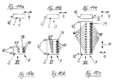
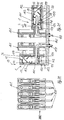
- 10a shows a 2-pin connector 1 with two contact springs 3 and two test openings 41.
- FIG. 10b shows a 5-pin connector 1
- FIG. 10c shows a 12-pin connector 1.
- FIGS. 13-24 A further embodiment of the connector 1 is shown in FIGS. 13-24. Those components which already exist in the same way in the embodiment of the connector 1 according to FIGS. 1-11 are provided with the same reference numerals in the embodiment of the connector 1 to be described below and are not explained in more detail.
- the insulating housing 102 of the connector 1 according to FIGS. 13 to 24 has an insertion opening 44 for receiving and fastening the stripped conductor end 12 of a conductor 11 (FIG. 14, FIG. 17).
- the insulating housing 102 facing away from the insertion opening 44, has a contact opening 147 and a contact opening 148 as connections to the element to be contacted.
- the element to be contacted is a connection pin 107 soldered to the printed circuit board 105 (FIGS. 18 to 21).
- the contact spring 103 fixes the conductor end 12 in the area of the insertion opening 44 and at the same time forms the connecting part to the contact pin 107. So that the connector 1 can be connected to a contact pin 107, the contact spring 103 is in the area of the contact opening 147 and in the area of the contact opening 148 of each penetrates a cylindrical connection opening. The opening edge of these connection openings is flanged into the insulating housing 102 in the manner of a tulip contact 124 (FIG. 19, FIG. 21). The tulip contact 124 interacts in the manner of a contact socket with the complementary contact pin 107.
- the central longitudinal axes 149 and 150 of the two tulip contacts 124 are at right angles to one another (FIG. 19, FIG. 21). In other words, the plug-in directions 4, 162 of the two tulip contacts 124 are at right angles to one another.
- rectilinear (Fig. 18) and right-angled (Fig. 20) contact pins 107 there are four different versions of the plugging processes and different relative positions of the connector 1 to the printed circuit board 105.
- Two cylindrical fixing pins 159 are formed on the insulating housing 102, which are formed over a housing base 127 of the insulating housing 102 protrude.
- the inserted connector 1 with the fixing pin 159 is supported either on the printed circuit board 105 or on a pin housing 161 receiving the bent contact pins 107.
- the tulip contact 124 is diametrically slotted by means of a longitudinal slot 151 or 152 running in the spring longitudinal direction 9 (FIG. 24).
- the longitudinal slot 151 is extended at one longitudinal end by a circular slot end 160, the longitudinal slot 152 by the rectangular shape of the fixing tab 30 in order to ensure sufficient elasticity of the tulip contacts 124.
- the contact spring 103 is an electrically conductive metal strip with a spring base body 114 lying in the plane of the strip or the drawing plane.
- the contact spring 103 has a plurality of partial strips separated from one another by bending edges 154, 155, 156.
- the partial strips are the spring base body 114, the spring roof 153, a spring side wall 157 connecting the spring base body 114 to the spring roof 153 and a connecting plate 158.
- the rectangular connecting plate 158 is separated from the spring side wall 157 by the bending edge 156 running in the transverse direction 19. In the final bending state, the immediately adjacent partial strips separated from each other by a bending edge are at right angles to each other and thereby form a cuboid box spring (Fig. 22, Fig. 23).
- connection plate 158 arranged in the region of the contact end 108 is penetrated centrally by a tulip contact 124.
- Another Tulip contact 124 passes through spring base body 114 in the region of its contact end 108 facing away from connection end 10 in spring longitudinal direction 9.
- the spring roof 153 has a tab-like end stop 138 that can be angled from its strip plane to limit the travel of the conductor end 12 in the insertion direction 13.
- the end stop 138 is arranged in the direction toward the spring base body 114 at right angles to the spring roof 153.
- the spring roof 153 is penetrated by a rectangular actuating slot 139.
- the insulating housing 102 is penetrated by a slot corresponding to the actuating slot 139.
- a tool for example the blade of a screwdriver, can be passed through the actuating slot 139.
- the free ends 16 of the contact spring 3 are pressed down in the bending direction 15, thereby clearing the way for the conductor 11 to the end stop for inserting the conductor 11 into the connector 1.
- the free end 16 springs back against the conductor 11 and holds it tight.
- the spring roof 153 is penetrated by a cylindrical test opening 141.
- the test opening 141 is aligned with the tulip contact 124 of the spring base body 114 (FIG. 23).
- the test opening 141 receives the straight contact pin 107, which is particularly high in construction, approximately in a form-fitting manner (FIG. 19).
- the two contact springs 203 lie opposite one another in the direction of spring force in the insulating housing 202 of the connector 1 arranged (Fig.12).
- the two contact springs 203 are identical.
- the contact spring 203 is, as it were, a combination of components of the contact spring 103 in the region of the connection end 10 and from the contact end 8 of the contact spring 3. With their contact ends 8, the two contact springs 203 clamp the circuit board 5 between them.
- Such a clamping of the circuit board 5 is particularly advantageous when the circuit board 5 is printed on both sides with conductor tracks 6. In this case, the clamping of the circuit board 5 can be used simultaneously from both sides for electrical contacting of conductor tracks 6 or contact fields 7.
- the contact end 8 of the contact spring 3, 203 is designed such that the part of the contact end 8 which acts on the conductor track 6 is integrally connected as a contact surface, for example by soldering to the conductor track 6.
- connector 1 is suitable for SMD (Surface Mounting Device) technology.
- additional feet are often arranged on the insulating housing of the connector 1, which are used in SMD technology to be able to absorb the tensile and compressive forces acting on the insulating housing during the mating processes and to relieve the solder joint.
Landscapes
- Coupling Device And Connection With Printed Circuit (AREA)
Abstract
Description
Die Erfindung betrifft einen elektrischen Steckverbinder mit den Merkmalen des Oberbegriffs des Anspruches 1.The invention relates to an electrical connector with the features of the preamble of
Bei einem aus US 3 360 767 vorbekannten Steckverbinder der eingangs genannten Art sind sowohl die Leiterplatte als auch ein elektrischer Leiter mittels Steckmontage mit der im Isoliergehäuse des Steckverbinders einliegenden Kontaktfeder elektrisch verbunden. Folglich ist sowohl die Verbindung Leiterplatte-Steckverbinder als auch die Verbindung Steckverbinder-Leiter durch eine direkte Steckverbindung realisiert. Nachteilig bei dem vorbekannten Steckverbinder ist die aufwendige Konstruktionsform der Kontaktfeder. Dadurch ist zum einen die Herstellung der Kontaktfeder teuer, zum anderen ist der Leiter vor seinem Einführen in den Steckverbinder am Leiterende mit einer elektrisch leitfähigen Metallhülse ausgestattet werden, deren Außenkontur dem Anschlußende der Kontaktfeder exakt angepaßt sein muß, wenn eine ausreichende Fixierung des Leiters im Isoliergehäuse des Steckverbinders gewährleistet sein soll. Dies bedingt weitere aufwendige Fertigungsschritte, bevor der vorbekannte Steckverbinder überhaupt erst einsatzbereit ist. Die aufwendige Außenkontur des Anschlußendes bewirkt, daß die Metallhülse beim Einführen des Leiters druckbeaufschlagt wird. Sodann kehrt das Anschlußende in seine Ausgangslage zurück und hintergreift die Metallhülse zur Verrastung des Leiters im Isoliergehäuse. Zum Lösen der Verrastung ist eine große Zugkraft am Leiter gegen dessen Einführrichtung notwendig. Dies ist für den Monteur unbequem. Außerdem führt ein derartiges Lösen der Verrastung zu einem raschen Materialverschleiß des Anschlußendes, wodurch bereits nach kurzer Betriebszeit die für die Verrastung notwendige Formschlußverbindung zwischen Anschlußende und Metallhülse nicht mehr gegeben ist. Eine ausreichende Fixierung und elektrische Kontaktierung des Leiters im Isoliergehäuse des Steckverbinders ist deshalb nicht gewährleistet.In a connector of the type mentioned at the beginning of US Pat. No. 3,360,767, both the printed circuit board and an electrical conductor are electrically connected by means of plug-in assembly to the contact spring lying in the insulating housing of the connector. As a result, both the circuit board-connector connection and the connector-conductor connection are realized by a direct plug connection. A disadvantage of the known connector is the complex design of the contact spring. On the one hand, this makes the production of the contact spring expensive, and on the other hand, the conductor must be equipped with an electrically conductive metal sleeve at the end of the conductor before it is inserted into the connector, the outer contour of which must be exactly matched to the connecting end of the contact spring if the conductor is adequately fixed in the insulating housing of the connector should be guaranteed. This requires further complex manufacturing steps before the known connector is even ready for use. The complex outer contour of the connection end causes the metal sleeve to be pressurized when the conductor is inserted. The connection end then returns to its starting position and engages behind the metal sleeve for locking the conductor in the insulating housing. A large tensile force on the conductor against its insertion direction is necessary to release the latching. This is inconvenient for the fitter. In addition, such a release of the latching leads to rapid material wear of the connection end, which means that after a short operating time, the positive connection required for the latching between Connection end and metal sleeve is no longer present. Adequate fixation and electrical contacting of the conductor in the insulating housing of the connector is therefore not guaranteed.
Der Erfindung liegt die Aufgabe zugrunde, die Steckmontage eines Steckverbinders der eingangs genannten Art zu vereinfachen und dessen Betriebssicherheit zu verbessern. Diese Aufgabe wird durch die Merkmalskombination des Anspruches 1 gelöst.The invention has for its object to simplify the plug-in assembly of a connector of the type mentioned and to improve its operational safety. This object is achieved by the combination of features of
Erfindungsgemäß beaufschlagt das Anschlußende der Kontaktfeder den in das Isoliergehäuse eingeführten Leiter unmittelbar mit Federkraft zum elektrischen Anschluß und zugleich zur Klemmfixierung des Leiters am Steckverbinder. Durch ihre Federelastizität paßt sich das Anschlußende an unterschiedliche Außenkonturen des Leiters bzw. des Leiterendes an, ohne daß hierbei Einbußen bei der elektrischen Anschlußsicherheit des Leiters im Isoliergehäuse des Steckverbinders entstehen. An dem erfindungsgemäßen Steckverbinder können deshalb unterschiedliche Leitertypen durch einen einfachen Steckvorgang an den Steckverbinder angeschlossen werden. Dies unterstützt die universelle Anwendbarkeit des erfindungsgemäßen Steckverbinders. So kann z.B. auch das abisolierte Lei terende eines herkömmlichen Leiters an den Steckverbinder angeschlossen werden. Vorteilhaft ist es außerdem, daß die Federkraft des Anschlußendes durch eine entsprechende Verarbeitung der Kontaktfeder und/oder durch die Federkonstante des ausgewählten Federwerkstoffs gewissermaßen vorprogrammierbar ist. Dadurch läßt sich das Anschlußende der Kontaktfeder noch besser an unterschiedliche Leiterquerschnitte anpassen. Erfindungsgemäß ist es deshalb ohne jegliche Konstruktionsänderungen des Isoliergehäuses möglich, daß konstruktiv identisch ausgebildete Kontaktfedern Anschlußenden mit unterschiedlicher Federkraft aufweisen, wenn an einen mehrpoligen Steckverbinder Leiter mit unterschiedlichen Leitungsquerschnitten angeschlossen werden sollen.According to the invention, the connection end of the contact spring acts directly on the conductor inserted into the insulating housing with spring force for the electrical connection and at the same time for the clamp fixation of the conductor on the plug connector. Due to their spring elasticity, the connection end adapts to different outer contours of the conductor or the conductor end, without any loss of electrical connection reliability of the conductor in the insulating housing of the connector. Different types of conductors can therefore be connected to the connector at the connector according to the invention by a simple plug-in process. This supports the universal applicability of the connector according to the invention. For example, the stripped conductor end of a conventional conductor can also be connected to the connector. It is also advantageous that the spring force of the connection end can be preprogrammed to a certain extent by appropriate processing of the contact spring and / or by the spring constant of the selected spring material. As a result, the connection end of the contact spring can be adapted even better to different conductor cross sections. According to the invention, it is therefore possible, without any design changes to the insulating housing, that contact springs of identical design have connection ends with different spring force if conductors with different line cross sections are to be connected to a multipole connector.
Die Maßnahmen nach Anspruch 2 vereinfachen die Steckmontage und die Anschlußsicherheit des Leiters zusätzlich. Hierzu ist das Anschlußende nach Art eines Widerhakens ausgebildet und beaufschlagt den Leiter zusätzlich mit einer etwa in Einführrichtung wirksamen Haltekraft, die ein unerwünschtes Herausziehen des Leiters aus dem Isoliergehäuse des Steckverbinders verhindert. Gemäß Anspruch 2 ist dieser Widerhaken fertigungstechnisch einfach durch einen abgewinkelten Abschnitt der Kontaktfeder gebildet, wodurch das Anschlußende auch platzsparend aufgebaut ist. Der Leiter biegt beim Einführen in das Isoliergehäuse das Anschlußende automatisch entgegen der Federkraft ab. Bei vollständig eingeführtem Leiter federt das Anschlußende ebenso automatisch zurück und klemmfixiert den Leiter mit seiner Federkraft.The measures according to
Gemäß Anspruch 3 ist die Kontaktfeder am Anschlußende längsgeschlitzt, so daß je Anschlußpol zwei voneinander unabhängige Leiter an die gleiche Kontaktfeder angeschlossen werden können. Dies ist besonders günstig, wenn die Leiter einen geringen Leitungsquerschnitt aufweisen, wie dies z.B. in der Fernmeldetechnik der Fall ist. In diesem Fall können vorteilhaft zwei Leiter mit dem gleichen Pol mechanisch und elektrisch verbunden werden.According to
Gemäß Anspruch 4 ist der Schwenkbereich des Anschlußendes während der Herstellung bzw. des Lösens der Klemmfixierung begrenzt. Hierdurch ist gewährleistet, daß das von außen durch den eingeführten Leiter oder ein Montagewerkzeug beaufschlagte Anschlußende über eine lange Betriebszeit hinweg eine konstante Federkraft aufweist.According to
Die Maßnahme nach Anspruch 5 unterstützt die mechanisch stabile Abstützung des von außen beaufschlagten und dadurch geschwenkten Anschlußendes am Anschlaglappen.The measure according to
Die Ansprüche 6 und 7 ermöglichen einen mechanisch zuverlässigen Halt und Sitz des gesteckten Verbinders, insbesondere des auf eine Leiterplatte gesteckten Verbinders. Nach Anspruch 7 ist der mechanische und elektrische Kontaktdruck der Kontaktfeder auf eine elektrische Kontaktstelle, insbesondere auf das Kontaktfeld einer Leiterplatte weiter verbessert.
Anspruch 8 unterstützt die Lagesicherung der gesamten Kontaktfeder innerhalb des Isoliergehäuses des Steckverbinders. Hierzu wird die Kontaktfeder montagetechnisch einfach in das Isoliergehäuse eingeschoben und rastet dort automatisch ein. Als Rastmittel dient hierbei ein vorzugsweise einstückig mit der Kontaktfeder verbundenes Hintergreifteil, welches mit einer im Isoliergehäuse angeformten Fixiernase zusammenwirkt. Somit ist die Kontaktfeder vor einem versehentlichen Herausziehen aus dem Isoliergehäuse entgegen der Einschubrichtung gesichert. Hingegen kann - sofern sinnvoll - ein gewolltes Lösen der eingerasteten Kontaktfeder mittels geeigneter Maßnahmen und/oder mittels in das Isoliergehäuse eingreifender Montagewerkzeuge vorgesehen sein.
Gemäß Anspruch 9 ist das Hintergreifteil zur Lagesicherung der Kontaktfeder mechanisch stabil und platzsparend am Federgrundkörper der Kontaktfeder angeordnet.According to
Anspruch 10 unterstützt die Herstellung und den Einsatz der Kontaktfeder als kostengünstigen Massenartikel.
Anspruch 11 begünstigt einen platzsparenden Aufbau der Kontaktfeder. Dadurch wird eine weitere Miniaturisierung des gesamten Steckverbinders vorteilhaft unterstützt.
Anspruch 12 begünstigt die Einteilung der Kontaktfeder in zwei voneinander unabhängig wirksame Hebelarme. Die Leiterplatte und der Leiter können deshalb vorteilhaft unabhängig voneinander mit der Kontaktfeder elektrisch kontaktiert werden, ohne daß es zu Beeinträchtigungen bei der Klemmfixierung oder der elektrischen Kontaktierung durch den jeweils anderen Hebelarm kommt.
Die Maßnahme nach Anspruch 13 erleichtert dem Monteur das montagegerechte Einführen eines Leiters in den Steckverbinder.The measure according to
Die Maßnahme nach Anspruch 14 schafft eine durchgängige Weiterbildung der Steckmontage des Steckverbinders. Hierzu sind am Isoliergehäuse ein oder mehrere Rasthaken angeordnet, welche federnd verrasten. Im Zusammenwirken mit einer Leiterplatte greifen diese Rasthaken in entsprechende Verriegelungsöffnungen der Leiterplatte ein. Auf diese Weise ist der Steckverbinder auf der Leiterplatte sicher verriegelt und gegen ungewollte Lageänderungen weiter stabilisiert.The measure according to
Gemäß Anspruch 16 bewerkstelligt die Kontaktfeder selbst die Klemmfixierung bzw. Steckmontage eines Leiters und eines zu kontaktierenden Elements. Da die Kontaktfeder aus elektrisch leitfähigem Metall besteht, weist sie über eine lange Betriebszeit hinweg gleichbleibend gute thermische und mechanische Eigenschaften auf. Dadurch lassen sich normungstechnische Anforderungen an die Klemmfixierung bzw. Steckmontage gut erfüllen. Außerdem kann das Isoliergehäuse aufgrund der wegfallenden thermisch/mechanischen Belastungen aus einem vergleichsweise minderwertigen und deshalb kostengünstigen Isolierkunststsoff hergestellt werden.According to
Gemäß Anspruch 17 kann der Verbinder in unterschiedlichen Relativlagen, insbesondere sowohl horizontal als auch vertikal gesteckt werden. Dadurch kann der Steckverbinder platzsparend an unterschiedlich vorhandene Raumverhältnisse oder geforderte Relativlagen angepaßt werden.According to
Anspruch 18 schlägt eine besonders einfache und mechanisch stabile Steckverbindung zwischen der Kontaktfeder und einem zu kontaktierenden Element vor. Bei diesem Element handelt es sich insbesondere um einen Kontaktstift der Leiterplatte, der auf der Leiterplatte unterschiedlich positioniert sein kann. Bei dieser "indirekten" Steckmontage zwischen Kontaktfeder und Leiterplatte ergeben sich im Vergleich zu einem direkten Aufstecken des Steckverbinders am Leiterplattenrand (![]()
![]()
![]()
![]()
Anspruch 19 stabilisiert die Steckmontage zusätzlich. Außerdem ist der Tulpenkontakt durch seinen Diametralschlitz federkontaktartig an unterschiedlich dimensionierte Kontaktstifte oder zu kontaktierende Elemente anpaßbar.
Anspruch 20 schafft eine besonders stabile Ausgestaltung der Kontaktfeder, wobei die über den Federgrundkörper hinausstehenden Bauteile einstückiger Bestandteil der Kontaktfeder sind.
Anspruch 23 schlägt ein stabiles Metall-Widerlager für das federschenkelartige Anschlußende vor. Dies verbessert die auf den angeschlossenen Leiter ausgeübte Klemmkraft.
Die Maßnahme nach Anspruch 24 erleichtert dem Monteur das montagegerechte Einführen eines Leiters in den Steckverbinder.The measure according to
Es handelt sich um einen mehrpoligen Steckverbinder, wenn eine Vielzahl von Leiterbahnen einer Leiterplatte elektrisch kontaktiert werden müssen. Vorzugsweise ist jeder Pol des Steckverbinders identisch, so daß auch konstruktiv identische Kontaktfedern in das Isoliergehäuse eingesetzt werden können. Die Anzahl der zu bevorratenden Bauteile für die Realisierung sämtlicher Ausführungsformen des Steckverbinders bleibt deshalb gering. Aufgrund der identischen Ausgestaltung der Anschlußpole des Isoliergehäuses können gleichartige Formwerkzeuge zur kostengünstigen Herstellung der Steckverbinder verwendet werden. Im Vergleich zu mehreren einpoligen Steckverbindern ist der mehrpolige Steckverbinder eine kompaktere und mechanisch stabilere Einheit. Gleichzeitig bleibt auch an einem mehrpoligen Steckverbinder mit großer Polanzahl der Anschluß auch vieler Leiter übersichtlich und montagefreundlich.It is a multi-pole connector if a large number of conductor tracks on a circuit board have to be contacted electrically. Each pole of the connector is preferably identical, so that structurally identical contact springs can also be used in the insulating housing. The number of components to be stored for the implementation of all embodiments of the connector therefore remains low. Due to the identical design of the connection poles of the insulating housing, similar molds can be used for the cost-effective production of the plug connectors. Compared to several single-pin connectors, the multi-pin connector is a more compact and mechanically stable unit. At the same time, even on a multi-pole connector with a large number of poles, the connection of many conductors remains clear and easy to install.
Der Erfindungsgegenstand wird anhand der in den Figuren dargestellten Ausführungsbeispiele näher erläutert. Es zeigen:
- Fig.1
- eine Draufsicht auf den erfindungsmäßigen Steckverbinder,
- Fig.2
- den Steckverbinder gemäß Schnitt II-II in Fig.1,
- Fig.3
- die Vorderansicht des Steckverbinders gemäß Pfeilrichtung III in Fig.2,
- Fig.4
- die Draufsicht auf den Steckverbinder gemäß Pfeilrichtung IV in Fig.2,
- Fig.5
- den Steckverbinder gemäß Schnitt V-V in Fig.1 mit angeschlossenem Leiter und auf die Leiterplatte aufgesteckt,
- Fig.6
- eine Draufsicht auf eine schematisch verkürzte Leiterplatte,
- Fig.7
- eine Seitenansicht der Kontaktfeder,
- Fig.8
- eine Draufsicht auf die Kontaktfeder im Ausgangszustand,
- Fig.9
- die Draufsicht auf die Kontaktfeder gemäß Pfeilrichtung IX in Fig.7,
- Fig.10
- drei Ausführungsbeispiele eines mehrpoligen Steckverbinders analog der Draufsicht in Fig.1 und
- Fig.11
- die Seitenansicht der Steckverbinder gemäß Pfeilrichtung XI in Fig.10.
- Fig.12
- eine geschnittene Seitenansicht auf den Steckverbinder in einer weiteren Ausführungsform,
- Fig.13
- eine Draufsicht auf den Steckverbinder in einer weiteren Ausführungsform,
- Fig.14
- den Steckverbinder gemäß Schnitt XIV-XIV in Fig.13,
- Fig.15
- die Vorderansicht des Steckverbinders gemäß Pfeilrichtung XV in Fig.14,
- Fig.16
- die Draufsicht auf den Steckverbinder gemäß Pfeilrichtung XVI in Fig.14,
- Fig.17
- den Steckverbinder gemäß Schnitt XVII-XVII in Fig.13,
- Fig.18
- eine Vorderansicht einer Stiftleiste mit fünf Kontaktstiften,
- Fig.19
- die geschnittene Seitenansicht der Stiftleiste gemäß Pfeilrichtung XIX in Fig.18 und eines an die Kontaktstifte angeschlossenen Steckverbinders,
- Fig.20
- die Vorderansicht einer weiteren Ausführungsform einer Stiftleiste mit fünf Kontaktstiften,
- Fig.21
- die geschnittene Seitenansicht der Stiftleiste gemäß Pfeilrichtung XXI in Fig.20 und eines an die Kontaktstifte angeschlossenen Steckverbinders,
- Fig.22
- eine Vorderansicht der vollständigen Kontaktfeder,
- Fig.23
- die geschnittene Seitenansicht der Kontaktfeder gemäß Schnitt XXIII-XXIII in Fig.22 und
- Fig.24
- eine Abwicklung der in Fig.22 und Fig.23 dargestellten Kontaktfeder.
- Fig. 1
- a plan view of the connector according to the invention,
- Fig. 2
- the connector according to section II-II in Fig.1,
- Fig. 3
- the front view of the connector according to arrow direction III in Figure 2,
- Fig. 4
- the top view of the connector according to arrow direction IV in Figure 2,
- Fig. 5
- the connector according to section VV in Fig. 1 with the conductor connected and plugged onto the circuit board,
- Fig. 6
- a plan view of a schematically shortened circuit board,
- Fig. 7
- a side view of the contact spring,
- Fig. 8
- a plan view of the contact spring in the initial state,
- Fig. 9
- the top view of the contact spring according to arrow direction IX in Figure 7,
- Fig. 10
- three embodiments of a multi-pin connector analogous to the plan view in Fig.1 and
- Fig. 11
- the side view of the connector according to arrow direction XI in Fig.10.
- Fig. 12
- 2 shows a sectional side view of the connector in a further embodiment,
- Fig. 13
- a plan view of the connector in a further embodiment,
- Fig. 14
- the connector according to section XIV-XIV in Fig. 13,
- Fig. 15
- the front view of the connector according to the direction of arrow XV in Fig. 14,
- Fig. 16
- the top view of the connector according to the direction of arrow XVI in Fig. 14,
- Fig. 17
- the connector according to section XVII-XVII in Fig. 13,
- Fig. 18
- a front view of a pin header with five contact pins,
- Fig. 19
- the sectional side view of the pin header according to the arrow direction XIX in Fig. 18 and a connector connected to the contact pins,
- Fig. 20
- the front view of a further embodiment of a pin header with five contact pins,
- Fig. 21
- the sectional side view of the pin header according to the direction of arrow XXI in Fig. 20 and a connector connected to the contact pins,
- Fig. 22
- a front view of the full contact spring,
- Fig. 23
- the sectional side view of the contact spring according to section XXIII-XXIII in Fig.22 and
- Fig. 24
- a development of the contact spring shown in Fig.22 and Fig.23.
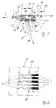
Der elektrische Steckverbinder 1 weist ein Isoliergehäuse 2 und je nach Polanzahl eine oder mehrere im Isoliergehäuse 2 angeordnete Kontaktfedern 3 auf (Fig.1,Fig.2). In Fig.5 ist der Steckverbinder 1 in Steckrichtung 4 auf eine Leiterplatte 5 aufgesteckt und mit einem eingesteckten Leiter 11 versehen.The
Die Leiterplatte 5 enthält mehrere Leiterbahnen 6, denen endseitig jeweils ein elektrisches Kontaktfeld 7 zugeordnet ist. Bei gestecktem Verbinder 1 liegt ein Kontaktende 8 der Kontaktfeder 3 unter mechanischer Vorspannung, d.h. unter Federspannung an einem Kontaktfeld 7 der Leiterplatte 5 an (Fig.5). Durch die Vorspannung ist die elektrische Verbindung zwischen der Kontaktfeder 3 und der zugeordneten Leiterbahn 6 hergestellt.The
Die Kontaktfeder 3 weist ein dem Kontaktende 8 in Federlängsrichtung 9 abgewandtes Anschlußende 10 auf. (Fig.5). Das Anschlußende 10 ist mit einem der Kontaktfeder 3 zugeordneten Leiter 11 elektrisch verbindbar. Das Anschlußende 10 beaufschlagt den Leiter 11 unmittelbar mit Federkraft. Auf diese Weise ist der elektrische Anschluß und zugleich eine Klemmfixierung des Leiters 11 am Steckverbinder 1 realisiert. In Fig.5 ist erkennbar, daß das Anschlußende 10 den Leiter 11 bzw. dessen abisoliertes Leiterende 12 unmittelbar gegen eine Gehäuseinnenwand des Isoliergehäuses 2 preßt. Hierdurch ist ein guter mechanischer Halt des abisolierten Endes 12 im Isoliergehäuse 2 gegeben.The
Die Klemmfixierung des Leiters 11 erfolgt derart, daß das Anschlußende 10 den in Einführrichtung 13 in das Isoliergehäuse 2 eingeführten Leiter 11 nach Art eines Widerhakens beaufschlagt. Dieser Widerhaken verhindert ein unerwünschtes Entfernen des Leiters 11 gegen die Einführrichtung 13. Das Anschlußende 10 ist als endseitiger Abschnitt mit der Kontaktfeder 3 zum Federgrundkörper 15 hin gerichtet, d.h. in Biegerichtung 15 umgebogen (Fig.7). Dabei bilden das Anschlußende 10 und der Federgrundkörper 14 einen spitzen Winkel α von etwa 40°-60°. Im Montagezustand der Kontaktfeder 3 wird das in das Isoliergehäuse 2 eingeführte Leiterende 12 durch das etwa in Einführrichtung 13 weisende Freiende 16 des Anschlußendes 10 klemmfixiert, wodurch die Widerhakenwirkung des Anschlußendes 10 entsteht.The
Anhand von Fig.7-Fig.9 wird die Kontaktfeder 3 näher beschrieben. Das Anschlußende 10 weist einen in Federlängsrichtung 9 verlaufenden Längsschlitz 17 auf. Dieser Längsschlitz 17 erstreckt sich vom Freiende 16 etwa bis zur kreisbogenförmigen Biegestelle 18 des Anschlußendes 10. Durch den Längsschlitz 17 ist das Anschlußende 10 in rechtwinklig zur Federlängsrichtung 9 angeordneten Querrichtung 19 zweigeteilt zur Bildung zweier Anschlußkontakte 20,21 für jeweils einen Leiter 11. Die Ebene des Federgrundkörpers 14 ist durch die Federlängsrichtung 9 und die Querrichtung 19 aufgespannt. Aus dieser Ebene ist zum umgebogenen Anschlußende 10 gerichtet ein Lappen 22 herausgebogen. Der Lappen 22 dient als Anschlag für das um seine Biegeachse 23 entgegen der Federkraft geschwenkte Anschlußende 10. Im Ausgangszustand des umgebogenen Anschlußendes 10 (Fig.7) steht der Anschlaglappen 22 etwa in einem rechten Winkel zum Anschlußende 10. Das Kontaktende 8 weist eine aus der Ebene des Federgrundkörpers 14 in Biegerichtung 15 hinausstehende Ausbiegung 24 auf. Die Ausbiegung 24 ist etwa V-förmig, wobei deren V-Grund bei gestecktem Verbinder 1 das Kontaktfeld 7 der Leiterplatte 5 beaufschlagt (Fig.5).The
Das Kontaktende 8 und das Anschlußende 10 stehen auf der gleichen Wirkseite 25 der Kontaktfeder 3 über den Federgrundkörper 14 hinaus. Im Montagezustand bildet die Kontaktfeder 3 einen zweiarmigen Hebel. Hierzu stützt sich die Kontaktfeder 3 zwischen dem Kontaktende 8 und dem Anschlußende 10 an einer quer zur Federlängsrichtung 9 verlaufenden Hebelnase 26 ab (Fig.2, Fig.5). Auf diese Weise bilden das Anschlußende 8 und das Kontaktende 10 zwei Hebelarme. Die Hebelnase 26 ist zwischen dem Kontaktende 8 und dem Anschlaglappen 22 angeordnet und an dem der Wirkseite 25 der Kontaktfeder 3 abgewandten Gehäuseboden 27 des Isoliergehäuses 2 angeformt.The
Die Kontaktfeder 3 wird entlang ihrer Längsrichtung 9 von der Steckseite 28 des Verbinders 1 her in das Isoliergehäuse 2 eingeschoben. Im eingeschobenen Zustand, d.h. im Montagezustand hintergreift die Kontaktfeder 3 eine am Gehäuseboden 27 angeformte, quer zur Federlängsrichtung 9 verlaufende Fixiernase 29 (Fig.2, Fig.5). Das Hintergreifteil der Kontaktfeder 3 ist als ein aus der Ebene des Federgrundkörpers 14 herausgebogener, mit dem Federgrundkörper 14 einen spitzen Winkel bildender Fixierlappen 30 ausgebildet (Fig. 7). Im Montagezustand der Kontaktfeder 3 befindet sich der Fixierlappen 30 in dem als Rastschacht 46 wirksamen Zwischenraum zwischen der Fixiernase 29 und der Hebelnase 26. Sofern sinnvoll, ist der Rastschacht 46 für einen Monteur mit Hilfe eines Spezialwerkzeuges von außen zugänglich. Auf diese Weise kann der Fixierlappen 30 beaufschlagt und dadurch die Verrastung der Kontaktfeder 3 gelöst werden. Im Wartungs- oder Reparaturfall ist die Kontaktfeder 3 deshalb einfach austauschbar.The
Die Kontaktfeder 3 ist ein elektrisch leitfähiger Metallstreifen mit der durch die Federlängsrichtung 9 und die Querrichtung 19 aufgespannten Streifenebene als Federgrundkörper 14 (Fig. 8). Die Kontaktfeder 3 ist durch Stanzen und Biegen hergestellt, wobei die der Biegestelle 18, der Ausbiegung 24, dem Anschlaglappen 22 und dem Fixierlappen 30 zugeordneten Biegeachsen 23,31,32 und 33 zueinander parallel sind (Fig. 7).The
Die in Federlängsrichtung 9 in das Isoliergehäuse 2 eingeschobene Kontaktfeder 3 stützt sich im Montagezustand an einem Widerlager 34 ab. Das Widerlager 34 ist am Gehäuseboden 27 angeformt. Das Widerlager verläuft quer zur Federlängsrichtung 9 und begrenzt dadurch den in Federlängsrichtung 9 verlaufenden Einschubweg der Kontaktfeder 3 in das Isoliergehäuse 2. In Fig. 2 und in Fig. 5 wird die Kontaktfeder 3 von der Steckseite 28 des Verbinders 1 her in das Isoliergehäuse 2 eingeschoben. Folglich ist das Widerlager 34 an der der Steckseite 28 abgewandten Einführseite 35 für den Leiter 11 angeordnet. Außerdem begrenzt das Widerlager 34 bei klemmfixiertem Leiter 11 den Verfahrweg des Anschlußendes 10 bzw. der Biegestelle 18 gegen die Federkraftrichtung (Fig. 5). Hierzu weist das Widerlager 34 eine sich zur Biegestelle 18 des Anschlußendes 10 hin öffnende Lagernut 36 auf (Fig. 2). Bei klemmfixiertem Leiter 11 ist die Biegestelle 18 und der sich daran anschließende Federgrundkörperabschnitt gegen die Lagernut 36 unter Federkraftwirkung fixiert (Fig. 5).The
An der dem Gehäuseboden 27 abgewandten Gehäuseoberseite 37 ist ein auf der Wirkseite 25 des Anschlußendes 10 in den Innenraum des Isoliergehäuses 2 hineinragender Endanschlag 38 angeformt. Er verläuft quer zur Einführrichtung 13 des Leiters 11 und begrenzt dadurch den Einführweg des Leiters 11 (Fig. 5). Die Gehäuseoberseite 37 ist auf der Wirkseite 25 des Anschlußendes 10 quer zur Einführrrichtung 13 von einem Sichtfenster 39 durchsetzt. Durch dieses Sichtfenster 39 ist leicht kontrollierbar, ob der Leiter 11 ordnungsgemäß in das Isoliergehäuse 2 eingeführt ist bzw. ob die Leiterisolierung 40 auch wirklich vom Leiterende 12 entfernt wurde. Auf der in Federlängsrichtung 9 dem Sichtfenster 39 abgewandten Seite des Endanschlages 38 ist die Gehäuseoberseite 37 von einer Prüföffnung 41 durchsetzt. Durch die Prüföffnung 41 hindurch ist ein hier nicht näher dargestelltes Prüfwerkzeug, z.B. ein Federstift, in das Isoliergehäuse 2 einführbar und mit der Kontaktfeder 3 elektrisch kontaktierbar. Dadurch ist es möglich, die Funktionsfähigkeit der Leiterbahnen 6 oder ganz allgemein elektrische Größen auf der Leiterplatte 5 zu überprüfen.An end stop 38 protruding into the interior of the insulating
Am Isoliergehäuse 2 des Steckverbinders 1 sind zwei über die Steckseite 28 hinausstehende Rasthaken 42 angeformt. Die Rasthaken verlaufen etwa in Federlängsrichtung 9 und sind parallel zueinander (Fig. 1, Fig. 4). Die beiden Rasthaken 42 sind an den beiden in Querrichtung 19 gegenüberliegenden Außenseiten des Isoliergehäuses 2 angeordnet. Bei gestecktem Verbinder 1 greifen die Rasthaken 42 in die Leiterplatte 5 durchsetzende Verriegelungsöffnungen 43 ein (Fig.5). Die derart verrasteten Rasthaken 42 geben dem gesteckten Verbinder 1 einen verbesserten mechanischen Halt gegen ein unerwünschtes Abziehen von der Leiterplatte 5.On the insulating
Das Kontaktende 8 und das Anschlußende 10 als die beiden Hebelarme der Kontaktfeder 3 arbeiten gewissermaßen unabhängig voneinander. Dadurch ist ein einzelner Leiter 11 sowohl bei gestecktem Verbinder 1 (Fig.5) als auch bei nicht gestecktem Verbinder 1 (Fig.2) durch ein ihm zugeordnetes Leiterauge 44 hindurch in das Isoliergehäuse 2 einführbar und wird mit Hilfe des Anschlußendes 10 klemmfixiert. Ebenso ist die Klemmfixierung des Leiters 11 lösbar, unabhängig davon, ob der Verbinder 1 gesteckt oder nicht gesteckt ist.The
Zur einfachen Lösung der Klemmfixierung ist die Einführseite 35 des Isoliergehäuses 2 von einer in Federlängsrichtung 9 mit dem Anschlußende 10 etwa fluchtenden Montageöffnung 45 durchsetzt. Durch die Montageöffnung 45 hindurch wird ein hier nicht näher dargestelltes Montagewerkzeug eingeführt, welches das Anschlußende 10 etwa in Einführrichtung 13 druckbeaufschlagt, wodurch das Anschlußende 10 gegen den Anschlaglappen 22 geschwenkt wird. Mit Hilfe dieser Montageöffnung 45 ist nicht nur das Lösen der Klemmfixierung vereinfacht, sondern auch die Klemmfixierung selbst. Daß das Anschlußende 10 druckbeaufschlagende Montagewerkzeug ermöglicht ein einfaches Einführen des Leiterendes 12 in das Isoliergehäuse 2 ohne wesentlichen Kraftaufwand, da die Federkraft des Anschlußendes 10 nicht durch den Leiter 11 überwunden werden muß. Dies ist besonders vorteilhaft, wenn das Leiterende 12 kein stabiler Draht, sondern eine flexible Drahtlitze ist.For a simple solution of the clamping fixation, the
Aus der Darstellung der Fig. 3 ist erkennbar, daß jedem, durch den Längsschlitz 17 zweigeteilten Anschlußende 10 der Kontaktfeder 3 zwei Leiteraugen 44 zugeordnet sind. Aus den Darstellungen der Fig.1 und Fig.10a,b,c schließlich ist erkennbar, daß jeder Kontaktfeder 3 eine Prüföffnung 41 zugeordnet ist. Fig.10a zeigt einen 2-poligen Steckverbinder 1 mit zwei Kontaktfedern 3 und zwei Prüföffnungen 41. Entsprechend zeigt Fig. 10b einen 5-poligen Steckverbinder 1 und Fig. 10c einen 12-poligen Steckverbinder 1.From the illustration in FIG. 3 it can be seen that each conductor end 44 of the
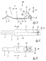
In Fig.13 - Fig.24 ist eine weitere Ausführungsform des Steckverbinders 1 dargestellt. Diejeigen Bauteile, die in gleicher Weise bereits bei der Ausführungsform des Steckverbinders 1 gemäß Fig. 1-11 existieren, sind in der nachfolgend zu beschreibenden Ausführungsform des Steckverbinders 1 mit gleichen Bezugszeichen versehen und werden nicht näher erläutert. Das Isoliergehäuse 102 des Steckverbinders 1 gemäß Fig.13 - Fig.24 weist eine Einführöffnung 44 zur Aufnahme und Befestigung des abisolierten Leiterendes 12 eines Leiters 11 auf (Fig.14, Fig.17). Der Einführöffnung 44 abgewandt weist das Isoliergehäuse 102 eine Kontaktöffnung 147 und eine Kontaktöffnung 148 als Anschlüsse an das zu kontaktierende Element auf. Bei dem zu kontaktierenden Element handelt es sich in den dargestellten Ausführungsbeispielen um einen an der Leiterplatte 105 angelöteten Anschlußstift 107 (Fig.18 bis Fig.21). Die Kontaktfeder 103 klemmfixiert das Leiterende 12 im Bereich der Einführöffnung 44 und bildet gleichzeitig das Anschlußteil an den Kontaktstift 107. Damit der Steckverbinder 1 an einen Kontaktstift 107 anschließbar ist, ist die Kontaktfeder 103 im Bereich der Kontaktöffnung 147 und im Bereich der Kontaktöffnung 148 von jeweils einer zylindrischen Anschlußöffnung durchsetzt. Der Öffnungsrand dieser Anschlußöffnungen ist in das Isoliergehäuse 102 hinein nach Art eines Tulpenkontakts 124 umgebördelt (Fig.19, Fig.21). Der Tulpenkontakt 124 wirkt nach Art einer Kontaktbuchse mit dem dazu komplementär ausgebildeten Kontaktstift 107 zusammen.A further embodiment of the
Die Mittellängsachsen 149 und 150 der beiden Tulpenkontakte 124 stehen rechtwinklig zueinander (Fig.19, Fig.21). Mit anderen Worten stehen die Steckrichtungen 4,162 der beiden Tulpenkontakte 124 rechtwinklig zueinander. Mit Hilfe von geradlinig (Fig.18) und rechtwinklig abgebogenen (Fig.20) Kontaktstifte 107 ergeben sich vier unterschiedliche Ausführungen der Steckvorgänge und unterschiedliche Relativstellungen des Steckverbinders 1 zur Leiterplatte 105. Am Isoliergehäuse 102 sind zwei zylindrische Fixierzapfen 159 angeformt, die über einen Gehäuseboden 127 des Isoliergehäuses 102 hinausstehen. Abhängig von der Ausführungsform des Kontaktstiftes 107 und dem angeschlossenen Tulpenkontakt 124 stützt sich der gesteckte Verbinder 1 mit dem Fixierzapfen 159 entweder an der Leiterplatte 105 oder an einem die abgebogenen Kontaktstifte 107 aufnehmenden Stiftgehäuse 161 ab. Damit der Tulpenkontakt 124 unter guter Federkraftwirkung an den Kontaktstift 107 anschließbar ist, ist der Tulpenkontakt 124 mittels eines in Federlängsrichtung 9 verlaufenden Längsschlitzes 151 bzw. 152 diametral geschlitzt (Fig.24). Der Längsschlitz 151 ist an einem Längsende durch ein kreisförmiges Schlitzende 160, der Längsschlitz 152 durch die rechteckige Ausformung des Fixierlappens 30 verlängert, um ausreichende Elastizität der Tulpenkontakte 124 zu gewährleisten.The central
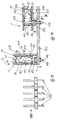
Die Kontaktfeder 103 ist ein elektrisch leitfähiger Metallstreifen mit in der Streifenebene bzw. Zeichnungsebene einliegendem Federgrundkörper 114. Die Kontaktfeder 103 weist mehrere, durch Biegekanten 154, 155, 156 voneinander getrennte Teilstreifen auf. Bei den Teilstreifen handelt es sich um den Federgrundkörper 114, das Federdach 153, eine den Federgrundkörper 114 mit dem Federdach 153 verbindende Federseitenwand 157 und eine Anschlußplatte 158. Die rechteckige Anschlußplatte 158 ist von der Federseitenwand 157 durch die in Querrichtung 19 verlaufende Biegekante 156 getrennt. Im Biegeendzustand stehen immer die unmittelbar benachbarten und durch eine Biegekante voneinander getrennten Teilstreifen rechtwinklig zueinander und bilden dadurch eine quaderförmige Kastenfeder (Fig.22, Fig.23). Die im Bereich des Kontaktendes 108 angeordnete Anschlußplatte 158 ist zentral von einem Tulpenkontakt 124 durchsetzt. Ein weiterer Tulpenkontakt 124 durchsetzt den Federgrundkörper 114 im Bereich seines dem Anschlußende 10 in Federlängsrichtung 9 abgewandten Kontaktendes 108.The
Das Federdach 153 weist einen von dessen Streifenebene abwinkelbaren, lappenartigen Endanschlag 138 zur Begrenzung des Verfahrweges des Leiterendes 12 in Einführrichtung 13 auf. Im Biegeendzustand der Kontaktfeder 103 ist der Endanschlag 138 in Richtung auf den Federgrundkörper 114 vorstehend rechtwinklig zum Federdach 153 angeordnet. In Federlängsrichtung 9 zwischen dem Endanschlag 138 und der Einführseite 35 für den Leiter 11 ist das Federdach 153 von einem rechteckförmigen Betätigungsschlitz 139 durchsetzt. Das Isoliergehäuse 102 ist von einer mit dem Betätigungsschlitz 139 korrespondierenden Schlitz durchsetzt. Durch den Betätigungsschlitz 139 ist ein Werkzeug, beispielsweise die Klinge eines Schraubendrehers hindurchführbar. Mit dem Werkzeug werden die Freienden 16 der Kontaktfeder 3 heruntergedrückt in Biegerichtung 15, wodurch der Weg für den Leiter 11 zum Endanschlag freigegeben ist zum Einführen des Leiters 11 in den Steckverbinder 1. Nach dem Enfernen des Werkzeugs federt das Freiende 16 gegen den Leiter 11 zurück und hält ihn kraftschlüssig. Auf der in Federlängsrichtung 9 dem Betätigungsschlitz 139 abgewandten Seite des Endanschlages 138 ist das Federdach 153 von einer zylindrischen Prüföffnung 141 durchsetzt. Die Prüföffnung 141 fluchtet im Biegeendzustand der Kontaktfeder 103 mit dem Tulpenkontakt 124 des Federgrundkörpers 114 (Fig.23). Durch die Prüföffnung 141 hindurch ist ein hier nicht näher dargestelltes Prüfwerkzeug, z.B. ein Federstift, in das Isoliergehäuse 102 einführbar und mit dem angeschlossenen Kontaktstift 107 bzw. mit der Kontaktfeder 103 elektrisch kontaktierbar. Dadurch ist es möglich, die Funktionsfähigkeit der Leiterbahnen 6 oder ganz allgemein elektrische Größen auf der Leiterplatte 5 zu überprüfen. Die Prüföffnung 141 nimmt bei gestecktem Verbinder 1 den besonders hoch aufgebauten geradlinigen Kontaktstift 107 etwa formschlüssig auf (Fig.19).The
In einer dritten Ausführungsform sind im Isoliergehäuse 202 des Steckverbinders 1 zwei in Federkraftrichtung einander gegenüberliegende Kontaktfedern 203 angeordnet (Fig.12). Die beiden Kontaktfedern 203 sind identisch. Die Kontaktfeder 203 ist gewissermaßen eine Kombination aus Bestandteilen der Kontaktfeder 103 im Bereich des Anschlußendes 10 und aus dem Kontaktende 8 der Kontaktfeder 3. Mit ihren Kontaktenden 8 klemmen die beiden Kontaktfedern 203 die Leiterplatte 5 zwischen sich ein. Eine derartige Einklemmung der Leiterplatte 5 ist insbesondere dann von Vorteil, wenn die Leiterplatte 5 beidseitig mit Leiterbahnen 6 bedruckt ist. In diesem Fall kann die Klemmung der Leiterplatte 5 von beiden Seiten her gleichzeitig für eine elektrische Kontaktierung von Leiterbahnen 6 bzw. Kontaktfeldern 7 genutzt werden.In a third embodiment, there are two contact springs 203 lying opposite one another in the direction of spring force in the insulating
In einer weiteren, hier nicht dargestellten Ausführungsform des Steckverbinders 1 ist das Kontaktende 8 der Kontaktfeder 3,203 derart ausgestaltet, daß der die Leiterbahn 6 beaufschlagende Teil des Kontaktendes 8 als Kontaktfläche stoffschlüssig, z.B. durch eine Lötung mit der Leiterbahn 6 verbunden ist. Auf diese Weise ist der Steckverbinder 1 für die SMD (Surface Mounting Device)-Technik geeignet. Außerdem sind am Isoliergehäuse des Steckverbinders 1 häufig Zusatzfüße angeordnet, die in der SMD-Technik dazu genutzt werden, die während der Steckvorgänge auf das Isoliergehäuse einwirkenden Zug- und Druckkräfte aufnehmen zu können und die Lötstelle zu entlasten.In a further embodiment of the
- 11
- SteckverbinderConnectors
- 22nd
- IsoliergehäuseInsulating housing
- 33rd
- KontaktfederContact spring
- 44th
- SteckrichtungDirection of insertion
- 55
- LeiterplatteCircuit board
- 66
- LeiterbahnConductor track
- 77
- KontaktfeldContact field
- 88th
- KontaktendeContact end
- 99
- FederlängsrichtungSpring longitudinal direction
- 1010th
- AnschlußendeConnection end
- 1111
- Leiterladder
- 1212th
- LeiterendeHead end
- 1313
- EinführrichtungDirection of insertion
- 1414
- FedergrundkörperSpring body
- 1515
- BiegerichtungBending direction
- 1616
- FreiendeFreeers
- 1717th
- LängsschlitzLongitudinal slot
- 1818th
- BiegestelleBending point
- 1919th
- QuerrichtungCross direction
- 2020th
- AnschlußkontaktConnection contact
- 2121
- AnschlußkontaktConnection contact
- 2222
- AnschlaglappenStop cloth
- 2323
- BiegeachseBending axis
- 2424th
- AusbiegungDeflection
- 2525th
- WirkseiteActive side
- 2626
- HebelnaseLever nose
- 2727
- GehäusebodenCase back
- 2828
- SteckseiteMating side
- 2929
- FixiernaseFixing nose
- 3030th
- FixierlappenFixing rag
- 3131
- BiegeachseBending axis
- 3232
- BiegeachseBending axis
- 3333
- BiegeachseBending axis
- 3434
- WiderlagerAbutment
- 3535
- EinführseiteIntroduction page
- 3636
- LagernutBearing groove
- 3737
- GehäuseoberseiteTop of the housing
- 3838
- EndanschlagEnd stop
- 3939
- SichtfensterViewing window
- 4040
- LeiterisolierungConductor insulation
- 4141
- PrüföffnungTest opening
- 4242
- RasthakenLocking hook
- 4343
- VerriegelungsöffnungLocking opening
- 4444
- LeiteraugeLadder eye
- 4545
- MontageöffnungAssembly opening
- 4646
- RastschachtRest shaft
- 102102
- IsoliergehäuseInsulating housing
- 103103
- KontaktfederContact spring
- 105105
- LeiterplatteCircuit board
- 107107
- KontaktstiftContact pin
- 108108
- KontaktendeContact end
- 114114
- FedergrundkörperSpring body
- 127127
- GehäusebodenCase back
- 137137
- GehäuseoberseiteTop of the housing
- 138138
- EndanschlagEnd stop
- 139139
- BetätigungsschlitzActuation slot
- 141141
- PrüföffnungTest opening
- 147147
- KontaktöffnungContact opening
- 148148
- KontaktöffnungContact opening
- 149149
- MittellängsachseCentral longitudinal axis
- 150150
- MittellängsachseCentral longitudinal axis
- 151151
- LängsschlitzLongitudinal slot
- 152152
- LängsschlitzLongitudinal slot
- 153153
- FederdachFeather roof
- 154154
- BiegekanteBending edge
- 155155
- BiegekanteBending edge
- 156156
- BiegekanteBending edge
- 157157
- FederseitenwandSpring side wall
- 158158
- AnschlußplatteConnection plate
- 159159
- FixierzapfenFixing pin
- 160160
- SchlitzendeSlot end
- 161161
- StiftgehäusePin housing
- 162162
- SteckrichtungDirection of insertion
- 202202
- IsoliergehäuseInsulating housing
- 203203
- KontaktfederContact spring
- 214214
- FedergrundkörperSpring body
- αα
- Winkelangle
Claims (24)
daß das Anschlußende (10) der Kontaktfeder (3,103,203) den Leiter (11) unmittelbar mit Federkraft beaufschlagt zum elektrischen Anschluß und zugleich zur Klemmfixierung des Leiters (11) am Steckverbinder (1).Electrical connector (1), in particular for a printed circuit board (5), with an insulating housing (2) and with at least one contact spring (3, 103, 203) arranged in the insulating housing (2),
that the connection end (10) of the contact spring (3, 103, 203) acts directly on the conductor (11) with spring force for the electrical connection and at the same time for the clamping fixation of the conductor (11) on the plug connector (1).
dadurch gekennzeichnet,
characterized,
dadurch gekennzeichnet,
daß das Anschlußende (10) durch einen in Federlängsrichtung (9) verlaufenden Längsschlitz (17) zweigeteilt ist zur Bildung zweier Anschlußkontakte (20,21) für jeweils einen Leiter (11).Connector according to claim 1 or 2,
characterized,
that the connection end (10) is divided into two by a longitudinal slot (17) running in the spring longitudinal direction (9) to form two connection contacts (20, 21) for each conductor (11).
gekennzeichnet durch
einen aus der Ebene des Federgrundkörpers (14,114,214) zum abgewinkelten Anschlußende (10) gerichtet hinausstehenden Lappen (22) als Anschlag für das entgegen der Federkraft geschwenkte Anschlußende (10).Connector according to claim 2 or 3,
marked by
a tab (22) projecting from the plane of the spring base body (14, 114, 214) towards the angled connection end (10) as a stop for the connection end (10) pivoted against the spring force.
dadurch gekennzeichnet,
daß der Anschlaglappen (22) im Ausgangszustand des abgewinkelten Anschlußendes (10) etwa in einem rechten Winkel zum Anschlußende (10) steht.Connector according to claim 4,
characterized,
that the stop tab (22) in the initial state of the angled connection end (10) is approximately at a right angle to the connection end (10).
dadurch gekennzeichnet,
daß das Kontaktende (8) eine aus der Ebene des Federgrundkörpers (14,214) hinausstehende Ausbiegung (24) aufweist.Connector according to one or more of the preceding claims,
characterized,
that the contact end (8) has a bend (24) protruding from the plane of the spring base body (14, 214).
gekennzeichnet durch
eine etwa V-förmige Ausbiegung (24), deren V-Grund bei gestecktem Verbinder (1) die elektrische Kontaktstelle, insbesondere ein Kontaktfeld (7) der Leiterplatte (5) beaufschlagt.Connector according to claim 6,
marked by
an approximately V-shaped bend (24), the V base of which acts on the electrical contact point, in particular a contact field (7) of the printed circuit board (5) when the connector (1) is inserted.
dadurch gekennzeichnet,
daß die entlang ihrer Längsrichtung (9), insbesondere von der Steckseite (28) des Verbinders (1) her in das Isoliergehäuse (2,102,202) eingeschobene Kontaktfeder (3,103,203) eine im Isoliergehäuse (2,102,202) angeformte, quer zur Federlängsrichtung (9) verlaufende Fixiernase (29) hintergreift.Connector according to one or more of the preceding claims,
characterized,
that the contact spring (3, 103, 203), which is inserted into the insulating housing (2, 102, 202) along its longitudinal direction (9), in particular from the plug-in side (28) of the connector (1), has a fixing lug (transversely to the longitudinal direction of the spring (9)) which is formed in the insulating housing (2, 102, 202) 29) engages behind.
dadurch gekennzeichnet,
daß das Hintergreifteil ein aus der Ebene des Federgrundkörpers (14,114,214) hinausstehender, mit dem Federgrundkörper (14,114,214) einen spitzen Winkel bildender Fixierlappen (30) ist.Connector according to claim 8,
characterized,
that the rear gripping part is a fixing tab (30) protruding from the plane of the spring base body (14,114,214) and forming an acute angle with the spring base body (14,114,214).
dadurch gekennzeichnet,
daß die Kontaktfeder (3,103,203) ein elektrisch leitfähiger Metallstreifen ist mit in der Streifenebene einliegendem Federgrundkörper (14,114,214).Connector according to one or more of the preceding claims,
characterized,
that the contact spring (3,103,203) is an electrically conductive metal strip with the spring base body (14,114,214) lying in the strip plane.
dadurch gekennzeichnet,
daß das Kontaktende (8) und das Anschlußende (10) auf der gleichen Wirkseite (25) der Kontaktfeder (3,203) über den Federgrundkörper (14,214) hinausstehen.Connector according to one or more of the preceding claims,
characterized,
that the contact end (8) and the connection end (10) on the same active side (25) of the contact spring (3,203) protrude beyond the spring base body (14,214).
dadurch gekennzeichnet,
daß sich die Kontaktfeder (3,203) im Montagezustand als zweiarmiger Hebel zwischen dem Kontaktende (8) und dem Anschlußende (10) an einer im Isoliergehäuse (2,202) der Wirkseite (25) der Kontaktfeder (3) abgewandt angeformten, quer zur Federlängsrichtung (9) verlaufenden Hebelnase (26) abstützt mit dem Kontaktende (8) und dem Anschlußende (10) als die beiden Hebelarme.Connector according to one or more of the preceding claims,
characterized,
that the contact spring (3, 203) is in the assembled state as a two-armed lever between the contact end (8) and the connection end (10) on one in the insulating housing (2, 202) of the active side (25) of the contact spring (3), which is formed transversely to the longitudinal direction of the spring (9) extending lever nose (26) supports with the contact end (8) and the connection end (10) as the two lever arms.
gekennzeichnet durch
einen im Isoliergehäuse (2) zwischen Steckseite (28) und Einführseite (35) auf der Wirkseite (25) des Anschlußendes (10) angeformten, quer zur Einführrichtung (13) des Leiters (11) verlaufenden Endanschlag (38) für das in das Isoliergehäuse (2) eingeführte Leiterende (12).Connector according to one or more of the preceding claims,
marked by
an end stop (38) formed in the insulating housing (2) between the plug-in side (28) and the insertion side (35) on the active side (25) of the connection end (10) and extending transversely to the insertion direction (13) of the conductor (11) for the into the insulating housing (2) inserted conductor end (12).
dadurch gekennzeichnet,
daß am Isoliergehäuse (2) mindestens ein an dessen Steckseite (28) hinausstehender und bei gestecktem Verbinder (1) verrastender, insbesondere in eine Verriegelungsöffnung (43) der Leiterplatte (5) eingreifender Rasthaken (42) angeformt ist.Connector according to one or more of the preceding claims,
characterized,
that at least one latching hook (42) protruding from the insulating housing (2) protruding from its plug-in side (28) and engaging when the connector (1) is inserted, in particular engaging in a locking opening (43) in the printed circuit board (5).
dadurch gekennzeichnet,
daß im Isoliergehäuse (202) zwei in Federkraftrichtung einander gegenüberliegende Kontaktfedern (203) angeordnet sind und mit ihren Kontaktenden (8) die elektrische Kontaktstelle, insbesondere ein Kontaktfeld (7) der Leiterplatte (5) zwischen sich klemmfixieren.Connector according to one or more of the preceding claims,
characterized,
that in the insulating housing (202) two opposite contact springs (203) are arranged in the direction of the spring force and with their contact ends (8) fix the electrical contact point, in particular a contact field (7) of the printed circuit board (5) between them.
dadurch gekennzeichnet,
daß die Kontaktfeder (103) allein sowohl den Leiter (11) klemmend fixiert als auch das Anschlußteil für die elektrische Kontaktstelle bildet.Connector according to claim 10,
characterized,
that the contact spring (103) alone fixes the conductor (11) in a clamping manner and also forms the connecting part for the electrical contact point.
dadurch gekennzeichnet,
characterized,
dadurch gekennzeichnet,
characterized,
dadurch gekennzeichnet,
daß der Tulpenkontakt (124) diametral geschlitzt ist.Connector according to claim 18,
characterized,
that the tulip contact (124) is diametrically slotted.
dadurch gekennzeichnet,
characterized,
dadurch gekennzeichnet,
daß die Kontaktfeder (103) als weiteren Teilstreifen eine durch eine Biegekante (156) von der Federseitenwand (157) getrennte Anschlußplatte (158) aufweist, welche
characterized,
that the contact spring (103) as a further partial strip has a connecting plate (158) which is separated from the spring side wall (157) by a bending edge (156) and which
dadurch gekennzeichnet,
daß ein dem Anschlußende (10) in Federlängsrichtung (9) abgewandtes Kontaktende (108) des Federgrundkörpers (114) einen Steckkontakt, insbesondere Tulpenkontakt (124) aufweist.Connector according to claim 20 or 21,
characterized,
that a contact end (108) of the spring base body (114) facing away from the connection end (10) in the spring longitudinal direction (9) has a plug contact, in particular a tulip contact (124).
dadurch gekennzeichnet,
daß die Kontaktfeder (103) den Leiter (11) zwischen Federdach (153) und Anschlußende (10) klemmfixiert.Connector according to one of claims 20 to 22,
characterized,
that the contact spring (103) fixes the conductor (11) between the spring roof (153) and the connection end (10).
dadurch gekennzeichnet,
characterized,
Priority Applications (1)
| Application Number | Priority Date | Filing Date | Title |
|---|---|---|---|
| DE29623742U DE29623742U1 (en) | 1995-03-31 | 1996-04-01 | Electrical connector, in particular for printed circuit boards |
Applications Claiming Priority (2)
| Application Number | Priority Date | Filing Date | Title |
|---|---|---|---|
| DE29506085 | 1995-03-31 | ||
| DE29506085U | 1995-03-31 |
Publications (2)
| Publication Number | Publication Date |
|---|---|
| EP0735616A2 true EP0735616A2 (en) | 1996-10-02 |
| EP0735616A3 EP0735616A3 (en) | 1997-03-19 |
Family
ID=8006639
Family Applications (1)
| Application Number | Title | Priority Date | Filing Date |
|---|---|---|---|
| EP96105169A Withdrawn EP0735616A3 (en) | 1995-03-31 | 1996-04-01 | Electric connector, especially for circuit boards |
Country Status (1)
| Country | Link |
|---|---|
| EP (1) | EP0735616A3 (en) |
Cited By (14)
| Publication number | Priority date | Publication date | Assignee | Title |
|---|---|---|---|---|
| EP0800233A1 (en) * | 1996-04-01 | 1997-10-08 | WIELAND ELECTRIC GmbH | Contact spring, specially adapted for an electrical connector |
| DE19710306A1 (en) * | 1997-02-26 | 1998-08-27 | Wago Verwaltungs Gmbh | Electric clamp for printed circuit boards and electrical devices |
| DE19710422C1 (en) * | 1997-03-13 | 1998-08-27 | Wieland Electric Gmbh | Socket or electrical connector with contact spring and socket as connection contact |
| DE19803085A1 (en) * | 1998-01-28 | 1999-08-05 | Metz Albert Ria Electronic | Single-pole or multi-pole conductor terminal clamp |
| EP0964478A2 (en) * | 1998-06-12 | 1999-12-15 | Molex Incorporated | Electrical connector |
| KR100406764B1 (en) * | 2001-04-04 | 2003-11-21 | 주식회사 일신이앤드씨 | Device for connecting wires |
| US7004781B2 (en) | 2003-06-06 | 2006-02-28 | Ria-Btr Produktions Gmbh | Terminal |
| EP1645175A1 (en) * | 2003-07-11 | 2006-04-12 | Arka Technologies Limited | Printed circuit board assembly |
| EP1850418A2 (en) | 2006-04-25 | 2007-10-31 | Wago Verwaltungsgesellschaft mbH | Electric connector |
| CN104025226A (en) * | 2011-12-28 | 2014-09-03 | 昭和电工株式会社 | Jig For Manufacturing Capacitor Element And Method For Manufacturing Capacitor Element |
| DE112006003111B4 (en) | 2005-11-18 | 2019-09-19 | Cree, Inc. | LED lighting units and arrangements with edge connections |
| CN114725868A (en) * | 2022-04-19 | 2022-07-08 | 山东西朗控股集团有限公司 | Intensive insulation plug-in bus duct with expansion self-adaptive structure |
| EP4089844A1 (en) * | 2021-05-12 | 2022-11-16 | Tridonic GmbH & Co. KG | Coupling arrangement for coupling a terminal connector to a circuit board arrangement |
| EP4231459A1 (en) * | 2022-02-18 | 2023-08-23 | Weidmüller Interface GmbH & Co. KG | Connection device and connection unit |
Citations (6)
| Publication number | Priority date | Publication date | Assignee | Title |
|---|---|---|---|---|
| US3069652A (en) * | 1959-03-23 | 1962-12-18 | Burndy Corp | Electrical connector for printed circuit boards |
| US3360767A (en) * | 1965-08-24 | 1967-12-26 | Hughes Aircraft Co | Electrical connector |
| EP0246199A2 (en) * | 1986-05-15 | 1987-11-19 | ELETTRO GIBI S.p.A. | An electrical connector |
| EP0361370A2 (en) * | 1988-09-24 | 1990-04-04 | AMPHENOL-TUCHEL ELECTRONICS GmbH | Chipcard reader |
| US5061203A (en) * | 1991-04-15 | 1991-10-29 | Amp Incorporated | Magnetic ballast connector system |
| US5401185A (en) * | 1993-11-22 | 1995-03-28 | Wang; Kuo-Long | Edge connector |
-
1996
- 1996-04-01 EP EP96105169A patent/EP0735616A3/en not_active Withdrawn
Patent Citations (6)
| Publication number | Priority date | Publication date | Assignee | Title |
|---|---|---|---|---|
| US3069652A (en) * | 1959-03-23 | 1962-12-18 | Burndy Corp | Electrical connector for printed circuit boards |
| US3360767A (en) * | 1965-08-24 | 1967-12-26 | Hughes Aircraft Co | Electrical connector |
| EP0246199A2 (en) * | 1986-05-15 | 1987-11-19 | ELETTRO GIBI S.p.A. | An electrical connector |
| EP0361370A2 (en) * | 1988-09-24 | 1990-04-04 | AMPHENOL-TUCHEL ELECTRONICS GmbH | Chipcard reader |
| US5061203A (en) * | 1991-04-15 | 1991-10-29 | Amp Incorporated | Magnetic ballast connector system |
| US5401185A (en) * | 1993-11-22 | 1995-03-28 | Wang; Kuo-Long | Edge connector |
Cited By (28)
| Publication number | Priority date | Publication date | Assignee | Title |
|---|---|---|---|---|
| EP0800233A1 (en) * | 1996-04-01 | 1997-10-08 | WIELAND ELECTRIC GmbH | Contact spring, specially adapted for an electrical connector |
| DE19710306A1 (en) * | 1997-02-26 | 1998-08-27 | Wago Verwaltungs Gmbh | Electric clamp for printed circuit boards and electrical devices |
| DE19710306C2 (en) * | 1997-02-26 | 2001-12-06 | Wago Verwaltungs Gmbh | Electrical clamp |
| DE19710422C1 (en) * | 1997-03-13 | 1998-08-27 | Wieland Electric Gmbh | Socket or electrical connector with contact spring and socket as connection contact |
| EP0865105A1 (en) * | 1997-03-13 | 1998-09-16 | Wieland Electric GmbH | Female electrical contact with contact spring and use as a terminal contact |
| DE19803085A1 (en) * | 1998-01-28 | 1999-08-05 | Metz Albert Ria Electronic | Single-pole or multi-pole conductor terminal clamp |
| US6109952A (en) * | 1998-01-28 | 2000-08-29 | Ria Electronic Albert Metz | Terminal connector assembly |
| EP0964478A2 (en) * | 1998-06-12 | 1999-12-15 | Molex Incorporated | Electrical connector |
| EP0964478A3 (en) * | 1998-06-12 | 2000-07-12 | Molex Incorporated | Electrical connector |
| KR100406764B1 (en) * | 2001-04-04 | 2003-11-21 | 주식회사 일신이앤드씨 | Device for connecting wires |
| US7004781B2 (en) | 2003-06-06 | 2006-02-28 | Ria-Btr Produktions Gmbh | Terminal |
| EP1645175A1 (en) * | 2003-07-11 | 2006-04-12 | Arka Technologies Limited | Printed circuit board assembly |
| DE112006003111B4 (en) | 2005-11-18 | 2019-09-19 | Cree, Inc. | LED lighting units and arrangements with edge connections |
| EP1850418A3 (en) * | 2006-04-25 | 2008-12-17 | Wago Verwaltungsgesellschaft mbH | Electric connector |
| US7704095B2 (en) | 2006-04-25 | 2010-04-27 | Wago Verwaltungsgesellschaft Mbh | Electrical connector |
| EP2246938A1 (en) * | 2006-04-25 | 2010-11-03 | Wago Verwaltungsgesellschaft mbH | Electr. connector |
| DE102007018443B4 (en) * | 2006-04-25 | 2013-11-21 | Wago Verwaltungsgesellschaft Mbh | Electrical connector |
| EP1850418A2 (en) | 2006-04-25 | 2007-10-31 | Wago Verwaltungsgesellschaft mbH | Electric connector |
| US9251954B2 (en) | 2011-12-28 | 2016-02-02 | Showa Denko K.K. | Jig for manufacturing capacitor element and method for manufacturing capacitor element |
| EP2800115A4 (en) * | 2011-12-28 | 2015-10-14 | Showa Denko Kk | Jig for manufacturing capacitor element and method for manufacturing capacitor element |
| CN104025226B (en) * | 2011-12-28 | 2017-06-30 | 昭和电工株式会社 | The manufacture method of capacitor element manufacture fixture and capacitor element |
| CN104025226A (en) * | 2011-12-28 | 2014-09-03 | 昭和电工株式会社 | Jig For Manufacturing Capacitor Element And Method For Manufacturing Capacitor Element |
| EP4089844A1 (en) * | 2021-05-12 | 2022-11-16 | Tridonic GmbH & Co. KG | Coupling arrangement for coupling a terminal connector to a circuit board arrangement |
| WO2022238262A1 (en) * | 2021-05-12 | 2022-11-17 | Tridonic Gmbh & Co Kg | Coupling arrangement for coupling a terminal connector to a circuit board arrangement |
| EP4231459A1 (en) * | 2022-02-18 | 2023-08-23 | Weidmüller Interface GmbH & Co. KG | Connection device and connection unit |
| DE102022103851A1 (en) | 2022-02-18 | 2023-08-24 | Weidmüller Interface GmbH & Co. KG | Connection device and connection unit |
| CN114725868A (en) * | 2022-04-19 | 2022-07-08 | 山东西朗控股集团有限公司 | Intensive insulation plug-in bus duct with expansion self-adaptive structure |
| CN114725868B (en) * | 2022-04-19 | 2024-01-12 | 西朗电气工业集团有限公司 | Dense insulating plug bus duct with expansion self-adaptive structure |
Also Published As
| Publication number | Publication date |
|---|---|
| EP0735616A3 (en) | 1997-03-19 |
Similar Documents
| Publication | Publication Date | Title |
|---|---|---|
| EP3324490B1 (en) | Spring clamp contact for connecting an electrical conductor, conductor connection terminal and method for manufacturing a spring clamp contact | |
| DE102010014144C5 (en) | Electrical connection terminal | |
| EP1641078B1 (en) | Electrical connector or connecting terminal | |
| DE102015107853B4 (en) | Conductor connection terminal | |
| DE102010014143B4 (en) | Actuation device for an electrical connection terminal | |
| DE2553558C3 (en) | Electrical plug connection | |
| DE102007022806B3 (en) | clamping member | |
| DE19753076C1 (en) | Electrical connector, esp. series connector | |
| EP0800233A1 (en) | Contact spring, specially adapted for an electrical connector | |
| EP3446366B1 (en) | Plug contact | |
| EP3118938B1 (en) | Connector | |
| DE202005005369U1 (en) | Connecting device for direct plug connection of conductor ends and electrical device with such a connection device | |
| EP1207588A1 (en) | Electrical connector for flat cable or flexible printed circuit | |
| EP3292591B1 (en) | Conductor connection clamp | |
| EP3375048A1 (en) | Plug contact | |
| DE202019105009U1 (en) | Conductor connection terminal | |
| EP0735616A2 (en) | Electric connector, especially for circuit boards | |
| DE102014117062B4 (en) | Spring-loaded terminal | |
| EP3136519B1 (en) | Connection device for connecting a conductor to a busbar | |
| WO2012084458A1 (en) | Electrical plug connector having an upstream contact terminal | |
| DE19731411A1 (en) | Holding device for small electric fan | |
| DE3922072A1 (en) | Electrical edge connector for circuit board - has latching clips that locate against board elements for retention | |
| WO2023078502A1 (en) | Contact carrier apparatus, connection device, actuator, plug-in connector insert and installation method, and cable connection system | |
| DE102018207788B4 (en) | Contact element and contact arrangement for relieving a solder joint | |
| DE10113063B4 (en) | Electrical connection or connection terminal |
Legal Events
| Date | Code | Title | Description |
|---|---|---|---|
| PUAI | Public reference made under article 153(3) epc to a published international application that has entered the european phase |
Free format text: ORIGINAL CODE: 0009012 |
|
| AK | Designated contracting states |
Kind code of ref document: A2 Designated state(s): CH DE DK FR GB IT LI SE |
|
| PUAL | Search report despatched |
Free format text: ORIGINAL CODE: 0009013 |
|
| AK | Designated contracting states |
Kind code of ref document: A3 Designated state(s): CH DE DK FR GB IT LI SE |
|
| RAP1 | Party data changed (applicant data changed or rights of an application transferred) |
Owner name: WIELAND ELECTRIC GMBH |
|
| 17P | Request for examination filed |
Effective date: 19970524 |
|
| 17Q | First examination report despatched |
Effective date: 19980929 |
|
| STAA | Information on the status of an ep patent application or granted ep patent |
Free format text: STATUS: THE APPLICATION IS DEEMED TO BE WITHDRAWN |
|
| 18D | Application deemed to be withdrawn |
Effective date: 19990410 |