The invention relates to an image processing method and
apparatus and more particularly to reception of a subject
facial input, image signal and generation of a feature
extraction tracking signal representing facial features of
the subject.
In the paper "Realtime Facial Image Recognition in
Unconstrained Environment for Interactive Visual
Interface" by Hasegawa et al published in ACCV '93 Asian
Conference on Computer vision, November 23-25, Osaka,
Japan pp. 763-766 a system is outlined in which features
such as the eyes and the nose are extracted as edges. The
tracking signal may be processed for integration of facial
features or for monitoring eye contact. Because feature
extraction involves monitoring feature edges, the amount
of useful information would appear to be limited. Little
technical information is given in the paper to describe
how the system operates. However, it is mentioned that
RGB colour information is calculated. The use of RGB
information generally leads to high complexity in the
image processing circuits.
The paper by J.F.S. Yau and N.D. Duffy entitled "A Feature
Tracking Method for Motion Parameter Estimation in a
Model-Based Coding Application" presented at the Third
International Conference on Image Processing and its
Applications held at Warick on 18-20th July 1989 and
published in IEE Conference Publication No. 307 at pages
531 to 535 describes a method of tracking a face. In this
method, there is a first phase which involves tracking the
eye, nose and mouth over the image sequence. This is
achieved by locating the facial features within the first
frame and then tracking them over subsequent frames using
block searching and code-book techniques. The result of
the first tracking phase is a description of the
trajectory of facial feature boxes over the image sequence
along the temporal axis. There is then a second phase
which involves motion parameter estimation whereby the
spatial distribution of the facial feature boxes for each
frame are interpreted to provide an estimate of position
and orientation. In this way, the dynamics of facial
movement are parameterised for application in a three-dimensional
model-based image coding scheme.
The output signal represents a facial image having feature
extraction information. It appears that this prior method
is intolerant to occlusion as once tracking of a feature
is lost it has difficulty re-locating it. Further,
processing must of necessity be complex as the interrelationship
of boxes is analysed on a frame-by-frame
basis.
Japanese Patent Specification No. JP 02141880 (Graphic
Communication Technologies) describes a system whereby an
image signal is divided into a grid of regions and there
is analysis of each region separately. The evaluation is
performed on a single image and does not involve
processing from frame to frame and the purpose of the
system is to discriminate a face in an image.
Japanese Patent Specification No. JP 63142986 (NEC)
describes a system which detects the facial area of an
image according to detection of mouth movement. A
suggested application for the system is that of obtaining
the image of a face and overlaying it upon a picture of
clean clothing. Accordingly, there is limited feature
extraction in these systems, and also therefore little
versatility.
In general, it could be said that the prior art shows
limited feature extraction.
The invention is directed towards providing a method and
apparatus for feature extraction which involves less
complexity than heretobefore.
Another object is to provide a tracking signal which is of
more benefit than heretobefore for down-stream processing
with a wider range of applications.
The invention is characterised in that :-
In one embodiment, only two of the H,S,V input image
components are used for generation of the facial area
location signal.
Preferably, the H and S components are passed through the
band pass filter for generation of the facial area
location signal.
In one embodiment, only two of the H,S,V input image
components are used for generation of the mouth location
signal.
Preferably, the S and V components are passed through the
band pass filter for generation of the mouth area location
signal.
In one embodiment, the band pass filter output signals are
analysed by mapping the output data over the pixel area
and generating a projection in a mapping axis and
analysing said projection, and preferably two projections
are generated, one for each axis in a two-dimensional
pixel area plane.
In another embodiment, each band pass filter comprises a
look-up table containing filter indicators which are
generated off-line.
Ideally, the step of analysing the filter output signals
comprises the further steps of determining maximum limits
in the pixel area for a feature and generating a bounding
box according to said limits.
In a further embodiment, the image processing for
generation of the eye area location signals comprises the
steps of correlation with template, and preferably the
image signal is normalised before correlation.
In another embodiment, the V component only of the input
image signal is used for generation of the eye location
signals.
In a further embodiment, the tracking signals which are
generated are post-processed to generate a facial
characteristic signal representing both location and
positional characteristic data, said signal being
generated by passing the tracking signals through logic
devices.
According to another aspect, the invention provides an
image processing apparatus comprising :-
Preferably, only the H and S components of the input image
signal are passed through the facial area band pass
filter.
In one embodiment, only the S and V components of the
input image signal are passed through the mouth location
band pass filter.
In a further embodiment, the apparatus further comprises
post-processing logic devices comprising means for
receiving the tracking signals and generating a facial
characteristic signal representing both location and
positional characteristic data.
The invention will be more clearly understood from the
following description of some embodiments thereof, given
by way of example only with reference to the accompanying
drawings, in which :-
Referring to the drawings, there is shown an image
processing apparatus comprising a facial
part detection
unit 31 and a post-processor 50. The facial
part
detection unit 31 takes an input video signal from a
camera, captures images and detects the facial parts such
as mouth, eyes, eye pupils, eyebrows etc. by colour region
monitoring and determines their positions within that
image. The output of the facial
part detection unit 31 is
a feature extraction tracking signal having a set of
positional parameters for the facial parts. These
parameters are :-
| Mlx, Mly, Mhx, Mhy | Specify the Mouth Box |
| Slx, Sly, Shx, Shy | Specify the Face Box |
| LEx, LEy | Specify the Left Eye Position |
| REx, REy | Specify the Right Eye Position |
| RPx, RPy | Specify the Right Pupil Position |
| RBx, RBy | Specify the Right Eyebrow Position |
| LPx, LPy | Specify the Left Pupil Position |
| LBx, LBy | Specify the Left Eyebrow Position |
The manner in which these parameters are generated is
described in more detail below. It will be appreciated
that such tracking signals are very comprehensive and
would be of benefit in a wide range of applications such
as sign language communication and data capture.
The
post processor 50 uses the positional parameters to
generate a set of facial characteristics so that the
facial feature position and orientation can be expressed.
These characteristics are :-
It would be possible to produce other information such as
distance by suitably processing the tracking signal.
Construction of the post-processor 50 is shown in Figs.
3(a) and 3(b) whereby various average, subtractor,
subtract and divide, and multiply circuits are used.
Referring now to Fig. 1, the facial part detection unit 31
is now described in more detail. The function of the unit
31 is to provide a feature extraction tracking signal
having feature extraction parameter values which are used
by the post processor 50 to generate a face vector. The
tracking signal may alternatively be independently
outputted.
The facial part detection unit 31 provides five different
feature extraction tracking signals, namely, A, B, C, D
and E.
The A output represents the mouth coordinates and is
provided by the following devices :-
The output B specifies the face box and is provided by the
following devices:-
Crop picture, find max/min and normalise grey scale
devices 3104, 3105 and 3106 respectively provide pre-processing
normalisation for the remaining outputs, C,D,
and E. The output C represents the left and right eye
positions and is provided by a device 3115 which
correlates with an eye template, and a find min device
3116.
The output D specifies the right pupil and eyebrow
positions and is provided by a right eye detection device
3117. Finally, the output E represents the left pupil and
eyebrow positions and is generated by a left eye detection
device 3118.
The converter 3101 takes as input a video signal (R, G, B,
Composite, etc.) and outputs digital values of the colour
represented in the HSV colour domain. The output is
passed to the band pass devices 3102 and 3103 and the pre-processing
normalisation devices 3104 to 3106. The band
pass device 3102 detects mouth colour and the band pass
device 3103 detects skin colour. The skin colour
detection signal passes to the face position detection
devices 3107, 3108 and 3109 which produce a box which
gives the position of the face in the image. The facial
box coordinates are passed to mouth position detection
devices 3110-3114 which search the facial box region to
determine the position of the mouth in the image. It is
of course implied that the mouth position is to be found
within the facial box.
The pre-processing-normalisation devices 3104 to 3106
normalise the pixels in the facial box before outputting
this image to eye position devices 3115 and 3116 and the
pupil and eyebrow position detection devices 3117 and
3118. The purpose of this is to increase the accuracy of
the correlation results in the eye position detection.
The eye position detection devices 3115 and 3116 correlate
the facial area of the normalised image with pre-stored
eye templates to determine the location of the eyes, and
produce two X,Y coordinates which specify the eye
locations within the image. These eye position
coordinates are passed to the pupil and eyebrow position
detection devices 3117 and 3118 which use these
coordinates to obtain areas around each eye which are then
post-processed to obtain the pupil and eyebrow positions
for each eye. An important aspect of operation of the
unit 31 is operation of the band pass devices to filter
the HV data and only pass through data which is shown to
be present in a colour template of the skin and face.
Referring now to the various diagrams of Fig. 2, the
devices 3101 to 3118 are described in more detail.
As shown in Fig. 2(a), the colour conversion device 3101
comprises an ADC, and a look-up table for each of the R,
G and B components, all connected to an RGB to HSV look-up
table. There are several different implementations of
this conversion which will be known to those people
skilled in the art.
The input stage has an arrangement in which the S and V
components are directed to the mouth detection filter 3102
and the H and S components are directed to the face
detection filter 3103. Thus, each of these series of
circuits must only process two components and may
therefore be quite simple. It has been found that a
combination of H (hue) which is essentially wavelength
data together with S (saturation) is particularly
effective for detecting skin. It has also been found that
the S and V (value) components are particularly effective
for distinguishing the mouth area within the already
identified facial (skin) area.
The purpose of the band pass device 3102 is to filter the
S,V data and only pass through data which has been shown
to be present in a colour template of the mouth. The
device 3102 is shown in circuit form in Fig. 2(b) and is
implemented as a look-up table (LUT). This may be an SRAM
which is programmed off-line, or alternatively a PROM
which is programmed in production. It has the same
construction as the filter 3103 for facial area detection.
The feature of receiving two of the H, S, and V components
for each of the mouth and face series of processing
circuits is important. This avoids the need for the very
large memories which are commonly required for the prior
R, G, B systems and, further, avoids the need for
backprojection in colour histogram matching techniques.
Instead, band pass filters 3102 and 3103 are used. The
two components (S,V for mouth area, HS for face) form an
address for the look-up table, which stores a value for
each address. The table values are generated off-line
according to reference mouth and face patterns. At its
simplest, the values may be at the bit-level giving YES or
NO indications for the particular S,V or H,S combinations.
The XY projection devices 3112 and 3107 perform the next
fundamental processing steps by mapping the retrieved
table values over the pixel area and generating XY
projections. Once this has been done, the next steps of
finding maximum limits and searching for the bounding box
can be easily implemented.
To put it simply, the band pass filtering and the XY
projection over the pixel area are the fundamental steps
and can be implemented by simple circuits. Further, the
down-stream steps are very simple to implement.
The purpose of the crop picture device 3110 is to limit
the image processing tasks to only the area determined by
the face position detection section as it receives the
facial area information from the device 3109. There are
two reasons for doing this. Firstly, as only a fraction
of the image is processed this increases the number of
frames which can be processed in a given time period.
Secondly, it allows local operations such as normalization
to be done on the facial area alone, unaffected by
external influences such as bright light sources in other
parts of the picture and random background noise. This
increases accuracy in such tasks as eye-tracking.
The purpose of the smoothing device 3111 shown in Fig.
2(d) is to aid mouth position detection in proceeding
image processing by the devices 3112-3114. It will be
noted that the face position detection stage (3107-3109)
and the mouth position detection stage (3110-3114) share
several common tasks, namely XY Projection, find max and
search for bounding box. However, the mouth position
detection stage includes two extra tasks which are not
shown in the face position detection, namely crop picture
and smoothing. The purpose of the crop picture device
3110 is explained above. The reason that smoothing is not
present in the face position detection derives from the
face that the task being undertaken is facial parts
identification and position location. This implies that
the face will occupy a large area in the input image. In
any image processing task there is a level of background
noise due to a variety of factors, for example,
inaccuracies in the conversion of analogue data to digital
data, stroboscopic effects from foreign lighting sources,
light deflation from glasses, etc.. These add noise to
the processed image. In the detection of the facial area,
since the skin will cover a large percentage of the input
image, there is a considerable number of pixels which will
be identified as belonging to the skin. Therefore, the
background noise will have little or no effect on the
results obtained from the face position detection.
However, the mouth occupies a much smaller area, and
therefore the background noise will have a much greater
effect on obtaining correct results from the mouth
position detection stage. The probability that a mouth
pixel is mistaken for a skin pixel and vice-versa is high
and affects mouth area detection. However, in the case of
face position detection the fact that a mouth pixel is
mistaken as a skin pixel actually helps in the location of
the facial area, since the mouth area lies within the face
area. However, the opposite applies for the mouth
position detection. To help overcome this problem the
image is smoothed before performing further image
processing steps. It is assumed that the background noise
is random in nature and will occur randomly over the
image, whereas the mouth pixel recognition is highly
concentrated in a single area. By averaging over an area,
the effects of the background noise an be reduced whilst
enhancing the areas where recognition is highly
concentrated. The principle behind the device 3111 is to
average all pixels within an 8 x 8 area, and place the
result at the central pixel point. The operation of this
circuit and its underlying principles will be understood
to those skilled in the art. The resulting image is a
smoothed representation of the input image.
Further image processing tasks are performed on the
smoothed image by the devices 3112-3114, namely XY
Projection, find max and search for bounding box. These
devices function in the same manner as the devices 3107 to
3109 in the face detection stage which are described in
detail below. The output from the device 3114 is a signal
indicating a box which defines an area in the input image
where the mouth is located.
The purpose of the device 3107 shown in Fig. 2(e) is to
perform an XY projection on the image which is outputted
from the device 3103 to effectively map the filter output
over the pixel area. The device 3107 can be divided into
two sections which operate in the same fashion, the left
hand side which evaluates the X projected data, and the
right hand side which evaluates the Y projected data. The
circuit comprises a 256 x 16 bit SRAM which is used to
store the X projected data, a multiplexer to arbitrate
access to the databus of the SRAM, a multiplexer to
arbitrate access to the address bus of the SRAM, an adder
to perform additions on the projected data, and a register
to act as an intermediate data store. The circuit
functions in the following manner. It is assumed that the
SRAM can have all bits set to zero, i.e. the SRAM can be
cleared, at the beginning of every XY projection, however,
this function is not shown in the diagram. It is also
assumed that the maximum image size is 256x256 pixels,
however, to those skilled in the art, it is possible to
adapt the circuits to handle large images. Pixel data is
inputted into the circuit through I/P pixel data, with the
address of each pixel being inputted through Row Addr and
Column Addr. It is assumed that the Select line is set so
that Row Addr signals impinge upon the SRAM, and that the
bi-directional buffer is configured to allow data to be
read from the SRAM into the ADDER. The Row Addr reads the
present X projection value from the SRAM into the ADDER
circuit. The ADDER adds together the data from the SRAM
and that of the I/P PIXEL DATA and puts the result into
the REGISTER. The bi-directional buffer is then
configured to write data from the REGISTER into the SRAM
so that the new result is stored. The next pixel value is
then inputted into the circuit with the new Row Addr
signal being used to select the appropriate X storage
location. The process is repeated until all pixels in the
image have been processed. By changing the select switch
to allow the External Row Addr to impinge upon the SRAM it
is possible to read out the final X projection values.
The operation of the Y projection is carried out in
parallel to the X projection.
The purpose of the device 3108 shown in Fig. 2(f) is to
find the maximum value in the X and Y projection data so
that an X and Y location which lies within the facial area
can be found. The device 3108 can be divided into two
sections, which both process in parallel and operate in
the same fashion. The basic principle of the circuit is
that each final projection value is compared using a
comparator CMP with a maximum value stored in REGISTER A.
If the projection data value is greater than the value in
REGISTER A then this new value is stored in REGISTER A,
whilst simultaneously the column address is stored in
REGISTER B. Data from the XY projection device 3107 is
read out serially, and impinges upon REGISTER A and CMP,
whilst the address is of the Projection value impinge upon
REGISTER B. The output of REGISTER A is also outputted to
CMP where the contents of REGISTER A and the Projection X
value are compared. If the result indicates that the
projected value is greater than the contents of REGISTER
A then a signal is generated in conjunction with the PIXEL
CLK which loads the new data value into REGISTER A, whilst
simultaneously loading the address of the pixel into
REGISTER B. This process is repeated for X(Y) projected
values. The values remaining in REGISTER A and B indicate
the maximum projected value and the location at which it
occurred.
The purpose of the device 3109 shown in Fig. 2(g) is to
determine the limits for a bounding box which will enclose
the skin area. This area will be used in subsequent image
processing tasks. The circuit can be divided into two
identical sections, the left hand side relating to finding
the boundaries, the right hand side to the Y boundaries.
This circuit uses information from the device 3108, namely
MAX X POSN, MAX X, MAX Y POSN and MAX Y. The operation of
the circuit is to derive a threshold value, XTH, for the X
data using MAX X, and a threshold value, YTH, for the Y
data using MAX Y. This is achieved by multiplying the MAX
X(Y) by a constant which is less than one. The constant
multipliers may be different for the X and Y data. The
next stage is to determine the lower boundary. By
starting at the MAX X POSN and repeatedly decrementing its
position whilst checking if the X Projection data at this
new location is less than the threshold value, XTH, the
point at which the X projected data goes beneath the
threshold can be found. This is the X LOWER BOUND. By
starting at the MAX X POSN and repeatedly incrementing its
position whilst checking if the X Projection data at this
new location is less than the threshold value, XTH, the
point at which the X projected data goes beneath the
threshold can be found. This is the X UPPER BOUND. The
calculation of the Y boundaries follows a similar fashion.
The circuit operation is as follows. The MAX X data from
the device 3108 is multiplied by CONST in MULT and the
result, which is XTH is passed to CMP, where all data from
I/P PROJECTION X DATA will be compared to XTH. The value
MAX X POSN, also from the device 3108, is loaded in
counter using the LOAD signal, originating from device 50.
The device 50 also provides control signals RST1 and RST2
which reset the RSA and RSB flip flops into the RESET
state. This will provide the address to look up the final
X Projection values in device 3107. The multiplexer in
the device 3107 is set so that the address from the
address from the External Row Addr impinges upon the SRAM.
In this way, the X Projection data values can be read from
the SRAM and into the divide 3109. Data from the device
3107 arrives at I/P PROJECTION X DATA where it is compared
against the XTH value. If the result of the comparator,
CMP, shows that the I/P PROJECTION X DATA is less than XTH,
then a signal is generated which causes the RS flip flops
RSA and RSB to be put in the SET position. The address in
the COUNTER is decremented until the comparator, CMP,
shows that the threshold has been exceeded, at which point
both flip flop RSA are placed in the SET state. The
signal from the flip flops is used to load REGISTER A with
the current COUNTER value which indicates the X LOWER
BOUND. The COUNTER is then loaded with the MAX X POSN
once again using the LOAD signal. This time, instead of
decrementing the COUNTER, the COUNTER is incremented until
the data once again exceeds the threshold value, XTH. This
time the RSB flip flop is placed in the SET state and the
output of RSB flip flop is used to load REGISTER B with
the value of COUNTER, which this time indicates the X
UPPER BOUND. The operation for the Y projected values is
the same. At the end of this process, the flip flops RSA
and RSB are reset using the control signals RST1 and RST2
from a control logic unit, not shown, and the process is
repeated for the next frame.
At this stage the bounding box for the facial area has
been discovered and a preliminary check can be carried
out. If the area of the box is found to be extremely
small, of the order of less than 20 pixels, then it can be
assumed that there is no face within the image and the
proceeding image processing tasks of finding the mouth and
eyes can be abandoned.
The pre-processing normalisation section uses the devices
3104-3106. The purpose of the pre-processing
normalisation section is to normalise the image before
performing correlation to increase the accuracy of the
results. This section does not perform image processing
on colour information, but on a grey scale image. The V
video signal of the HSV video standard is a grey scale
representation of the input image.
The purpose of the crop device 3104 shown in Fig. 2(c) is
to limit the image processing tasks to only the area
determined by the face position detection section and not
the whole image. The reasons for doing this are explained
above.
The find max/min device 3105 is shown in circuit form in
Fig. 2(h). The purpose of this device is to find the
maximum and minimum pixel values within the image. This
information is to be used in the proceeding image
processing stage. The device 3105 is comprised of two
registers, REGISTER A and REGISTER B, and two comparators,
CMP A and CMP B, REGISTER A and CMP A are used to find the
MAX VALUE, whereas REGISTER B and CMP B are used to find
the MIN VALUE. The pixel data from the input image is
inputted serially via the PIXEL DATA input. The data
impinges upon both registers and both comparators.
REGISTER A is used as a temporary storage area for the
maximum value, MAX VALUE, whereas REGISTER B is used as a
temporary storage for the minimum value, MIN VALUE. At
the beginning of each frame REGISTER A must be set to 0
and REGISTER B must be set to 255 by a control unit which
transmits a control signal CLR. The output of REGISTER A
is input to the CMP A where it is compared to the input
data. If the result from the comparator CMP A shows that
the input data is greater than the data stored in REGISTER
A then the comparator generators a LOAD signal which loads
the input pixel data into REGISTER A. The operation for
minimum value uses the same principle with the comparator
generating a load signal when the result from the
comparator CMP B shows that the input data is less than
the data stored in REGISTER B. After all pixels in the
input image have been processed through the circuit the
maximum value resides in MAX VALUE, and the minimum value
resides in MIN VALUE. Before the next input image can be
processed both registers must be initialised to their
respective values.
The normalise
grey scale device 3106 is shown in circuit
form in Fig. 2(i). The purpose of this stage is to
translate the input image in such as way that it uses the
full range of possible values, namely 0 to 255. The
device 3105 processed the image and found the maximum
values. In an 8 bit grey scale representation the minimum
value possible is 0, and the maximum value possible is
255. However, results from the
device 3105 will indicate
that from frame to frame the maximum and minimum values
found will not be the maximum and minimum possible.
Therefore, it is advantageous that a method be devised
that changes the input image so that it fits the full
range of values. The simplest method, as shown in Fig.
2(i) is that of a look-up table, 31068, which for an 8 bit
input and 8 bit output requires a 256x8 bit memory. This
look-up table must be programmed frame by frame, as the
maximum and minimum values will change frame by frame.
The algorithm for programming the look-up table is as
follows :-
255 ≤ x < Max Coeff(x) = 255
Max ≤ x ≤ Min Coeff(x) = (int) (255 * (x - Min)/(Max -
Min)
Min < x ≤ 0 Coeff(x) = 0
where the values Max and Min refer to the values of MAX
VALUE and MIN VALUE calculated by the
device 3105. Max
and Min must be between the values of 0 and 255, and Max
> Min. Fig. 2(i) shows that the circuit of the
device
3106 is made up of devices 31061-31069. The circuit has
two modes of operation. The first where the coefficients
of the look-up table are calculated and the other where
these coefficients are to convert the input image into the
normalized output image. The parts 31061 - 31067 are
involved with the calculation of the coefficients which
are stored in the
SRAM 31068. The data is transformed by
allowing the PIXEL DATA to impinge upon the SRAM as the
address by the control unit setting the SELECT control
signal to the correct state. At the start of each frame
all locations in the LUT are set to zero and the MIN VALUE
is loaded into a counter, indicated as the
part 31061.
The MIN VALUE along with MAX VALUE are obtained from the
device 3105. The counter is loaded using a LOAD control
signal from the
control logic unit 50, not shown. The
output of the counter is inputted to a comparator CMP,
which compares the counter value with the MAX VALUE. If
the value of the counter is greater than MAX VALUE then
this indicates that all coefficients have been loaded into
look-up table and that the normalization process can
start. The comparator CMP outputs a control signal named
FINISHED. The coefficient calculation can be divided into
three steps. In the first step two calculations occur in
parallel, namely,
| (a) MIN VALUE - x | where x is the present counter value |
| (b) MAX VALUE - MIN VALUE |
| then, |
| (c) CONST x (Result of 1) | using part 31066 |
| then, |
| (d) (Result of 3)/(Result of 2) | using part 31067 |
The value of CONST is set to 255. The SELECT switch of
the multiplexer MUX is set to allow the output of the
counter to impinge upon the address bus of the SRAM. By
setting the R/W line to the SRAM to write the results from
the division part 31067 are written into the SRAM at the
location specified by the counter 31061. The counter is
then incremented and the process repeated until the
comparator CMP, indicates that all coefficients have been
calculated and stored in the SRAM. At this point the
look-up table to normalise the input image. The SELECT
signal is switched to allow the PIXEL DATA to impinge upon
the address bus of the SRAM and the R/W control signal is
switched to read. The input image is then presented to
the SRAM where it is transformed by the look-up table and
outputted to the NORMALIZED PIXEL DATA stage. When all
pixels have been transformed the counter is again loaded
with MIN VALUE, all LUT locations are set to zero, and the
process is repeated.
The output of the pre-processing-normalisation section is
passed to two further sections, namely the eye position
detection stage which finds the eye positions, and the
pupil and eyebrow position detection stage which finds the
eye pupil and eyebrow positions.
The eye position detection stage has two devices, the
correlate with eye template device 3115 and the find max
device 3116. The eye position detection is processed
twice, once with templates for the left eye, and once with
the templates for the right eye.
The correlate with
eye template device 3115 is shown in
circuit form in Fig. 2(j). The purpose of the
device 3115
is to correlate the input image against several pre-stored
templates of right and left eye images. The result
closest to zero from the right eye correlation indicates
the position of the right eye, and the result closest to
zero from the left eye correlation indicates the position
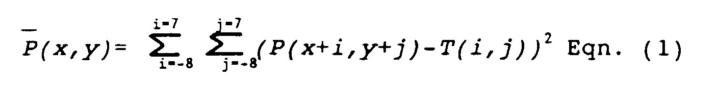
of the left eye. The correlator circuit comprises a
circuit which implements the following mathematical
function in integer arithmetic, using only 4 bits of
accuracy.
where P is the input image, T is the template image, x and
y are positional indicators within the input image. This
equation is computed for each pixel in the output image.
The algorithm computes the square of all differences
between pixels in the input image and the template image.
In the case that the input image and the template image
are identical the result is zero, the accuracy can be
improved by adding more bits, however, this leads to a
more complex hardware implementation.
Equation (1) can be simplified so show the basic image
processing steps which are needed to implement this
equation.
wherein T(i,j)
2 is a constant, P(i,j)
2 is the sum of all
pixels squared in the input image, and P(i,j)T(i,j) is the
multiplication and summation of all pixels in the input
image with the corresponding pixel in the template image.
It can be clearly seen that the algorithm can be divided
into several steps, some of which can be executed in
parallel.
This reduces the calculation to four basic steps.
The device 3115 has parts 31151-31156. The parts 31511
and 31153 are 16 x 16 8 bit correlators, part 31151
performing the P(i,j)T(i,j) and part 31153 performing
31153 performing the P(i,j)2. The part 31152 is an 256 x
8 SRAM which is used as a lookup table to convert the
input image pixel values to their squared values before
correlation. This is required so that numerical accuracy
is maintained throughout the correlation process.
The results from the correlation are inputted to the find
min device 3116 where the minimum value and the position
of the minimum value are found. A circuit of the device
3116 is shown in Fig. 2(k). It can be seen from the
diagram that the device 3116 is similar to the device 3108
and operation of both circuits is identical.
It is envisaged that the eye position detection stage can
be expanded so that multiple eye templates can be
correlated and the best correlation value found. The
implementation of this type of system will be clear to
those skilled in the art.
The final output from the eye position detection system
are two pixel locations, (LEx,LEy) and (REx,REy), which
define the location of left and right eye in the input
image.
The devices 3117 and 3118 (shown in Fig. 2(1)), for right
eye detection and left eye detection, make up the pupil
and eyebrow position detection stage. The purpose of the
pupil and eyebrow position detection stage is to use the
eye coordinates, (LEx,LEy) and (REx,REy), obtained from
the device 3116, together with the normalized image from
the device 3106, to find the positions of the eye pupil
and eyebrow for both the left and right eyes.
The device 3117 for right eye detection is shown in
circuit form in Fig. 2(l). The device 3117 is comprised
of parts 31171-31175. The first part 31171, known as crop
picture, is used to obtain a region of interest, using the
right eye coordinates (REx,REy) as the central pixel.
This sub-image is then outputted to the part 31172, known
as X Projection which performs an X projection on the sub-image.
The circuit to implement the part 31172 is shown
in Fig. 2(n). The functioning of the part 31172 is
identical to that of the device 3107.
The data from the device 31172 is passed to the device
31173 for smoothing where the X projection data is
smoothed from the uppermost row of sub-image to the
lowest. A circuit which implements the device 31173 is
shown in Fig. 2(m). The principle behind this circuit is
that the serial input stream is averaged over four pixel
values and the output is the averaged pixel stream. In
order to average, the pixels are stored in REGISTERs with
the outputs being fed to adders. The result from the
adders is then outputted to a SHIFTER, which shifts the
result right by two places, corresponding to a divide by
4. The next pixel is then inputted to the circuit and
stored in the first REGISTER. In parallel the previous
stored data is shifted along the REGISTER chain. The new
average is then computed and outputted. This process is
repeated until all X projected data has been smoothed.
The averaged X projected data from the part 31173 is then
passed to the device 31174. The purpose of this device is
to search the averaged X projected data from the uppermost
row value to the lowermost row value and find the maximum
peak in the data. This peak corresponds to the y
coordinate location of the eyebrow. A circuit which
implements the part 31174 is shown in Fig. 2(o). The
principle of this circuit is to locate the position where
the (N+1)th data value is less than the Nth data value,
since this shows that a peak has been encountered. The
(N+1)th and Nth data values are provided by the REGISTERs,
whose outputs are fed to a COMPARATOR which compares the
values and outputs a SET signal to an RS flip flop when
the (N+1)th data value is less than the Nth data value. The
RS flip flop is used to issue a load signal to two
REGISTERS which store the pixel value and the location at
which is occurred. This data represents to y location of
the eyebrow, RBy. The RBx location it is assumed to be
the same as REx. Hence the location of the brow is now
located at (RBx,RBy).
The purpose of the find minimum part 31175 is to find the
position of the pupil. This is done by finding the
minimum value in the normalised image. The circuit which
is used to implement the part 31175 is shown in Fig. 2(p).
Since the operation of this circuit is identical to that
of the devices 3108 and 3113 it is not explained. The
output of this circuit is the coordinate of the right eye
pupil, (RPx,RPy).
The part 3118 is similar to device 3117, but differs in
that it uses the coordinates of the left eye, (LEx,LEy),
to crop the image.
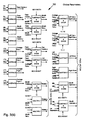
Referring now to Figs. 3(a) and 3(b), the following
functions are carried out by the various parts of the
post-processor 50 to convert the received facial part
position parameters to the facial characteristics.
| Initialisation Parameters |
| Lip Separation.y | = Mly-Mhy |
| Lip Separation.x | = Mlx-Mhx |
| Average Eye.x | = (LEx + REx)/2 |
| Average Eye.y | = (LEy + REx)/2 |
| Average Pupil.x | = (LPx + RPx)/2 |
| Average Pupil.y | = (LPy + RPy)/2 |
| Offset Eye.x | = Average Eye.x-Average Pupil.x |
| Offset Eye.y | = Average Eye.y-Average Pupil.y |
| Offset Left Brow | = LBy - Average Eye.y |
| Offset Right Brow | = RBy - Average Eye.y |
| Online Parameters |
| Average Eye.x | = (LEx + REx)/2 |
| Average Eye.y | = (LEy + REx)/2 |
| Average Pupil.x | = (LPx + RPx)/2 |
| Average Pupil.y | = (LPy + RPy)/2 |
| Face Centre.x | = (Slx + Shx)/2 |
| Face Centre.y | = (Sly + Shy)/2 |
| Mouth Centre.x | = (Mlx + Mhx)/2 |
| Mouth Centre.y | = (Mly + Mhy)/2 |
| Mouth Rel.x | = (Face Centre.x - Mouth Centre.x)/BOX WIDTH |
| Mouth Rel.y | = (Mouth Centre.y - Face Centre.y)/BOX HEIGHT |
| Eye Centre.x | = (Face Centre.x - Average Eye.x)/BOX WIDTH |
| Eye Centre.y | = (Face Centre.y - Average Eye.y)/BOX HEIGHT |
| Rotate.z | = (Average Eye.x - Mouth Centre.x)/10 |
| Rotate.y | = CONST1 * Mouth Rel.y |
| Rotate.x | = CONST2 * Mouth Rel.x |
| Left Eye.x | = Right Eye.x = (Average Eye.x - Average Pupil.x - Offset Eye.x) * 10/4 |
| Left Eye.y | = Right Eye.y = (Average Pupil.y - Offset Eye.y)* 10/12 |
| Left Brow | = Left Brow.y - Average Eye.y - Offset Left Brow |
| Right Brow | = Right Brow.y - Average Eye.y - Offset Right Brow |
| Mouth Openness.x | = (Mlx - Mhx - Lip Separation.x)/BOX WIDTH |
| Mouth Openness.y | = (Mly - Mhy - Lip Separation.y)/BOX HEIGHT |
The last nine variables (underlined) which are calculated
by use of the online parameters constitute a face vector.
The face vector is transmitted from the post-processor 50
for use in the desired application. Because of the
comprehensive nature of this signal, it has a wide range
of uses.
It will be appreciated that the invention provides an
apparatus which is very simple because of the nature and
routing of input image data. Further, the output signals
are very comprehensive in their content - including
location data in terms of regions of pixels rather than
edges. This data can additionally be used to provide very
useful facial characteristic data signals for down-stream
processing. Such processing may include capture of
expressions, sign language communication, videophone
communication, computer animation or facial substitution
in video images both in single frame or real time video
acquisition.