EP0727889A2 - Optical transmission system for cable television signals and video- and telecommunication signals - Google Patents
Optical transmission system for cable television signals and video- and telecommunication signals Download PDFInfo
- Publication number
- EP0727889A2 EP0727889A2 EP96102246A EP96102246A EP0727889A2 EP 0727889 A2 EP0727889 A2 EP 0727889A2 EP 96102246 A EP96102246 A EP 96102246A EP 96102246 A EP96102246 A EP 96102246A EP 0727889 A2 EP0727889 A2 EP 0727889A2
- Authority
- EP
- European Patent Office
- Prior art keywords
- signals
- subscriber
- optical
- frequency
- cable television
- Prior art date
- Legal status (The legal status is an assumption and is not a legal conclusion. Google has not performed a legal analysis and makes no representation as to the accuracy of the status listed.)
- Granted
Links
Images

Classifications
-
- H—ELECTRICITY
- H04—ELECTRIC COMMUNICATION TECHNIQUE
- H04N—PICTORIAL COMMUNICATION, e.g. TELEVISION
- H04N7/00—Television systems
- H04N7/22—Adaptations for optical transmission
-
- H—ELECTRICITY
- H04—ELECTRIC COMMUNICATION TECHNIQUE
- H04J—MULTIPLEX COMMUNICATION
- H04J14/00—Optical multiplex systems
- H04J14/02—Wavelength-division multiplex systems
- H04J14/0226—Fixed carrier allocation, e.g. according to service
-
- H—ELECTRICITY
- H04—ELECTRIC COMMUNICATION TECHNIQUE
- H04J—MULTIPLEX COMMUNICATION
- H04J14/00—Optical multiplex systems
- H04J14/02—Wavelength-division multiplex systems
- H04J14/0227—Operation, administration, maintenance or provisioning [OAMP] of WDM networks, e.g. media access, routing or wavelength allocation
- H04J14/0228—Wavelength allocation for communications one-to-all, e.g. broadcasting wavelengths
- H04J14/023—Wavelength allocation for communications one-to-all, e.g. broadcasting wavelengths in WDM passive optical networks [WDM-PON]
- H04J14/0232—Wavelength allocation for communications one-to-all, e.g. broadcasting wavelengths in WDM passive optical networks [WDM-PON] for downstream transmission
-
- H—ELECTRICITY
- H04—ELECTRIC COMMUNICATION TECHNIQUE
- H04J—MULTIPLEX COMMUNICATION
- H04J14/00—Optical multiplex systems
- H04J14/02—Wavelength-division multiplex systems
- H04J14/0227—Operation, administration, maintenance or provisioning [OAMP] of WDM networks, e.g. media access, routing or wavelength allocation
- H04J14/0241—Wavelength allocation for communications one-to-one, e.g. unicasting wavelengths
- H04J14/0242—Wavelength allocation for communications one-to-one, e.g. unicasting wavelengths in WDM-PON
- H04J14/0245—Wavelength allocation for communications one-to-one, e.g. unicasting wavelengths in WDM-PON for downstream transmission, e.g. optical line terminal [OLT] to ONU
- H04J14/0247—Sharing one wavelength for at least a group of ONUs
-
- H—ELECTRICITY
- H04—ELECTRIC COMMUNICATION TECHNIQUE
- H04J—MULTIPLEX COMMUNICATION
- H04J14/00—Optical multiplex systems
- H04J14/02—Wavelength-division multiplex systems
- H04J14/0227—Operation, administration, maintenance or provisioning [OAMP] of WDM networks, e.g. media access, routing or wavelength allocation
- H04J14/0241—Wavelength allocation for communications one-to-one, e.g. unicasting wavelengths
- H04J14/0242—Wavelength allocation for communications one-to-one, e.g. unicasting wavelengths in WDM-PON
- H04J14/0249—Wavelength allocation for communications one-to-one, e.g. unicasting wavelengths in WDM-PON for upstream transmission, e.g. ONU-to-OLT or ONU-to-ONU
- H04J14/0252—Sharing one wavelength for at least a group of ONUs, e.g. for transmissions from-ONU-to-OLT or from-ONU-to-ONU
-
- H—ELECTRICITY
- H04—ELECTRIC COMMUNICATION TECHNIQUE
- H04J—MULTIPLEX COMMUNICATION
- H04J14/00—Optical multiplex systems
- H04J14/02—Wavelength-division multiplex systems
- H04J14/0278—WDM optical network architectures
- H04J14/0282—WDM tree architectures
-
- H—ELECTRICITY
- H04—ELECTRIC COMMUNICATION TECHNIQUE
- H04J—MULTIPLEX COMMUNICATION
- H04J14/00—Optical multiplex systems
- H04J14/02—Wavelength-division multiplex systems
Definitions
- the invention relates to an optical transmission system according to the preamble of patent claim 1 and an optical network termination device according to the preamble of patent claim 2.
- FIG. 1 An optical transmission system with the features mentioned in the preamble of claim 1 is known, e.g. from: L. Adnet et al, "Optoelectronics in the Subscriber Line", Electrical Communication (Alcatel), 4th Quarter 1992, pages 58 to 65.
- FIG. 1 An optical transmission system in a general FTTB architecture. From a switching and distribution facility, cable television and subscriber-specific telecommunication signals are transmitted via an optical fiber distribution network to a building in which there are several subscribers.
- This optical transmission system is made up of two subsystems: a narrowband part, with which subscriber-specific telecommunication signals are transmitted, and a broadband part for cable television signals to be distributed via the optical fiber distribution network.
- the cable television signals are transmitted with light of a wavelength of 1550 nm, and the subscriber-specific telecommunication signals are transmitted with light of a wavelength of 1300 nm; the narrow band part enables bidirectional transmission.
- the cable television signal is fed to the optical network termination for the broadband system (BONT) and the subscriber-specific telecommunication signal is fed to the optical network termination for the narrowband system.
- BONT broadband system
- optical network terminations convert the received optical signals into electrical signals corresponding to these signals, which are then transmitted to the subscribers via coaxial cable (cable television signal) or via copper cable (subscriber-specific telecommunication signal).
- Such a subscriber-specific service is e.g. a video on demand service.
- a transmission system that enables such a video retrieval service is known from M. Yamashita et al, "Optical Video Transport / Distribution System with Video on Demand Service", SPIE, Vol. 1817, Optical Communications (1992), pages 12 to 22
- a transmission system is shown there, which has a ring-shaped distribution network.
- the subscriber-specific video signals that have to be transmitted from the central office (there called “basic unit") to subscribers to the cable television distribution network in order to carry out the video retrieval service are transmitted there as analog signals.
- the video signals are each modulated onto subcarriers with different frequencies, the modulating subcarriers (37 pieces) are combined to form a frequency division multiplex signal and this is transmitted in wavelength division multiplex with the cable television signals to optical network terminations (called ONUs there).
- Table 1 shows that multiple wavelengths are used in order to offer a total of 400 cable television subscribers the option of viewing individual video programs.
- Optical transmission systems in which subscriber-specific services are to be offered must be inexpensive in order to achieve corresponding acceptance among the subscribers. In other words, high costs on the subscriber side must be avoided in such optical transmission systems. This also means that as few changes in the structure of existing optical transmission systems as possible are necessary. The assumption is therefore that a significant part of cable television distribution networks, which have a chance of being introduced somewhere in the near future, has the property that the fiber optic distribution network does not reach the homes or apartments of the participants, but ends at the roadside in optical network terminations and is continued from there through an electrical connection network to the participants.
- the invention has for its object to provide an inexpensive, optical transmission system for the transmission of cable television signals and subscriber-specific video and telecommunications signals.
- An optical transmission system that solves the problem is the subject of patent claim 1.
- the invention is also based on the object of specifying an optical network termination device for an optical transmission system.
- An optical network termination device that achieves this object is the subject of claim 2.
- Advantageous refinements of the invention are specified in the subclaims.
- An advantage of the invention is that the electrical signals are combined in the optical network termination device that conventional broadband TV amplifiers can be used, which are optimized for the respective frequency ranges of the electrical signals.
- Another advantage of the invention is that only one broadband TV amplifier is required in one embodiment.
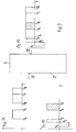
- This optical transmission system includes from a center 1, two optical fibers 6, 7, an optical network termination device 3, an electrical connection network 2 and terminals 4 (telephone and / or television) at the subscriber.
- Branching points are usually provided in the optical waveguides 6, 7, through which the light which propagates, for example, in the optical waveguide 6, is divided up into a plurality of optical waveguides, which in turn are each connected to optical network termination devices. From headquarters 1 emitted signals can also be transmitted in wavelength division multiplexing via a common optical fiber. This is not shown in FIG. 1.
- the optical fibers 6, 7 generally form an optical fiber distribution network.
- the control center 1 has an output 12 for light with which the cable television signal is to be transmitted.
- One end of the optical waveguide 6 is connected to this output 12 and its other end is connected to an input 20 of the optical network termination device 3.
- One end of the optical waveguide 7 is connected to a connection 13 of the control center 1 and its other end is connected to a connection 21 of the optical network termination device 3.
- the connections 13, 21 are inputs and outputs, since light is transmitted bidirectionally in the optical waveguide 7.
- Another connection 22 of the optical network termination device 3 is also an input and an output; this connection 22 is connected to the electrical connection network 2, to which terminals 4 of several subscribers are connected. In Fig. 1 only the terminals 4 of a participant are shown.
- the center 1 is, for example, a local exchange (OVST) which is connected to other exchanges in the public telecommunications network.
- the cable TV signals S TV can be supplied to the control center 1, for example via an existing satellite reception antenna or via optical fibers.
- the center 1 has a cable television device 32, which provides the cable television signals S TV for transmission.
- a electro-optical converter 33 which is connected to the output 12, sends the cable television signals S TV as an optical signal via the optical waveguide 6 to the optical network termination device 3.
- the cable television signals S TV can be transmitted, for example, with light of a wavelength of 1500 nm.
- the center 1 has a local exchange (OVst) 39 for the subscriber-specific telecommunication signals.
- the function of the local exchange 39 is generally known, so that the function is not described in detail.
- control center 1 Another function of the control center 1 is to provide subscriber-specific video signals.
- the control center 1 has a video device 34, a time-division multiplexing device 35, a frequency-division multiplexing device 36 and an electro-optical converter 37.
- An opto-electrical converter 38 present in the control center 1 receives optical signals which are transmitted from the terminals 4 to the local exchange 39.
- the optoelectric converter 38 and the electro-optical converter 37 are connected to the terminal 13.
- the video device 34 is a so-called video server.
- the video device 34 has outputs for analog or digital signals.
- the outputs (eg four outputs) of the video device 34 are connected to the time-division multiplexing device 35, through which a channel is assigned to each video film. The participant has access to the channel in which their desired film is broadcast.
- the time-division multiplex signal exiting time-division multiplexer 35, in which the video signals are contained, is fed to frequency division multiplexer 36.
- Frequency-division multiplexing device 36 combines the subscriber-specific video signals (time-division multiplex signal) and the subscriber-specific telecommunication signals coming from the local exchange 39 to form a first frequency-division multiplex signal S T , which converts from the electro-optical converter 37 into an optical signal corresponding to the first frequency division multiplex signal S T.
- the first frequency division multiplex signal S T is transmitted, for example, with light of a wavelength of 1300 nm.
- the subscriber-specific video signals and the subscriber-specific telecommunication signals are thus transmitted as the first frequency division multiplex signal S T.
- the cable television signals S TV are not included in this first frequency division multiplex signal S T.
- the control center 1 informs the subscriber on which channel and at what time the video film is transmitted.
- subscriber-specific signals e.g. Audio signals (music, lecture, lecture) are transmitted to the participant on demand.
- Each subscriber participating in the video retrieval service selects and receives the subscriber-specific video signal intended for him from the set of subscriber-specific video signals which are distributed to a group of subscribers which are connected to an optical network termination device 3.
- the frequency ranges of the signals must be set in such a way that there is no overlap in the frequency range.
- the frequency ranges of the signals are discussed in more detail in connection with FIG. 2.
- the amplifier 27 merges and amplifies the cable television signals S TV and the video signals.
- the frequency ranges of these two signals are chosen so that they do not overlap.
- a third frequency multiplex signal thus emerges from the amplifier 27, which is composed of the cable television signals S TV and the video signals and which is fed to the filter device 31.
- the telecommunication signals amplified by the amplifier 28 are fed to the filter device 31 via the filter device 30.
- the filter device 31 is also a combination of a high-pass filter and a low-pass filter. This filter device 31 is designed such that subscriber-specific telecommunication signals coming from the connection 22 are blocked by the high-pass filter, which is located in a first signal path, and thus do not reach the first amplifier 27.
- the third frequency division multiplex signal (cable television and video signals) coming from the amplifier 27, on the other hand, is passed through by the high-pass filter.
- the filter device 30 is likewise a combination of a high-pass filter and a low-pass filter.
- the filter device 30 is designed such that it passes the subscriber-specific telecommunication signals coming from the amplifier 28 unhindered to the filter device 31 and only allows the subscriber-specific telecommunication signals to be transmitted in the direction of the center 1 to the amplifier 29.
- the third frequency multiplex signal and the subscriber-specific telecommunication signals coming from the filter device 30 are combined on the filter device 31 to form a second frequency multiplex signal S S , which exits at the output 22.
- this second frequency division multiplex signal S S S all signals to be transmitted are contained and are transmitted via an electrical connection network 2.
- subscriber-specific telecommunication signals e.g. Telephone and data signals (up-link) are transmitted to the control center, which are also routed via the optical network termination device 3. To ensure this, there is a separate signal path for this direction. From the connection 22, the subscriber-specific telecommunication signals are routed via the two filter devices 31, 30 to the amplifier 29 and from there to the electro-optical converter 25. The telecommunication signals which are then present as an optical signal emerge from the optical network termination device 3 at the connection 21.
- subscriber-specific telecommunication signals e.g. Telephone and data signals (up-link) are transmitted to the control center, which are also routed via the optical network termination device 3. To ensure this, there is a separate signal path for this direction. From the connection 22, the subscriber-specific telecommunication signals are routed via the two filter devices 31, 30 to the amplifier 29 and from there to the electro-optical converter 25. The telecommunication signals which are then present as an optical signal emerge from the optical network termination device 3 at the connection 21.
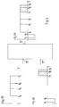
- the frequency plans are arranged with reference to the optical network termination device 3 shown schematically in FIG. 2, ie the frequency plan of the cable television signals S TV is at the input 20, the frequency plan of the first frequency multiplex signal S T (subscriber-specific video and telecommunication signals) is at the connection 21. and at the connection 22 the frequency plan of the second frequency multiplex signal propagating in the connection network 2 is shown.
- the cable television signals with S TV , the first frequency division multiplex signal with S T and the second frequency division multiplex signal, which propagates in the access network 2 are denoted with S S.
- S S For occurring frequencies f 1 to f 8 applies that the frequency increases from f 1 to f 8 .
- the first frequency plan, ie S TV (f) shows that the cable television signals have three frequency ranges: a first frequency range lies between the frequencies f 4 and f 5 , a second frequency range between the frequencies f 6 and f 7 , and a third frequency range between the frequencies f 7 and f 8 .
- the second frequency plan ie S T (f) shows that the first frequency multiplex signal S T (subscriber-specific video and telecommunications signal) has three frequency ranges:
- a first frequency range lies between the frequencies f 1 and f 2 , a second frequency range between the frequencies f 2 and f 3 and a third frequency range between the frequencies f 5 and f 6 (this frequency range is hatched in FIG. 3).
- the first frequency range is defined for the transmission of telecommunication signals to the head office (up-link). To indicate that it is for this direction of transmission, it is shown in the frequency plan with a negative amplitude. Another frequency range, which is defined for monitoring the transmission, is not shown.
- the third frequency plan, ie S S (f), shows that the signal that propagates in the connection network 2 results from a combination of all signals to be transmitted.
- the frequencies f 1 to f 8 are chosen so that they do not overlap, so that no information is lost.
- the specified frequency values are reference values to show the frequency distribution.
- Adjacent frequency ranges eg AM-VSB range and video signal range (f 5 ), are of course chosen so that they do not overlap; there is a sufficient frequency separation.
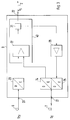
- FIG. 3 shows a further exemplary embodiment of an optical network termination device 3. It differs from the optical network termination device 3 shown in FIG. 1 in that no filter devices 26, 30 and no amplifier 28 are present.
- the remaining components of the optical network termination device 3 shown in FIG. 3 have the same reference numerals as those shown in FIG. 1.
- the electrical signal (electrical frequency division multiplex signal S T ) coming from the optoelectric converter 24 is fed directly to the amplifier 27. There, the cable television signal S TV and the first frequency division multiplex signal S T are brought together and amplified. No amplifier 28 is needed in this embodiment.
- the amplifier 29 is connected directly to the filter device 31.
- the frequency ranges are to be selected in accordance with the frequency plans shown in FIG. 4.
- the frequency plan S TV (f) for the cable television signal S TV occupies the frequency ranges between f 4 and f 5 , between f 5 and f 6 and between f 6 and f 7 .
- the frequency plan S T (f) for the subscriber-specific video and telecommunications signals occupies the frequency ranges between f 1 and f 2 , between f 7 and f 8 , and between f 8 and f 9 .
- the frequency plan S s (f) is the combination of all signals to be transmitted.
- the subscriber-specific video and telecommunication signals are arranged in the frequency range above the cable television signals.
Abstract
Description
Die Erfindung betrifft ein optisches Übertragungssystem nach dem Oberbegriff des Patentanspruchs 1 und eine optische Netzabschlußeinrichtung gemäß dem Oberbegriff des Patentanspruchs 2.The invention relates to an optical transmission system according to the preamble of patent claim 1 and an optical network termination device according to the preamble of
Ein optisches Übertragungssystem mit den im Oberbegriff des Patentanspruchs 1 genannten Merkmalen ist bekannt, z.B. aus: L. Adnet et al, "Optoelektronik in der Teilnehmeranschlußleitung", Elektrisches Nachrichtenwesen (Alcatel), 4. Quartal 1992, Seiten 58 bis 65. Dort ist in Fig. 1 ein optisches Übertragungssystem in einer allgemeinen FTTB-Architektur gezeigt. Von einer Vermittlungs- und Verteileinrichtung aus werden Kabelfernseh- und teilnehmerindividuelle Telekommunikationssignale über ein Lichtwellenleiter-Verteilnetz zu einem Gebäude übertragen, in dem sich mehrere Teilnehmer befinden.An optical transmission system with the features mentioned in the preamble of claim 1 is known, e.g. from: L. Adnet et al, "Optoelectronics in the Subscriber Line", Electrical Communication (Alcatel), 4th Quarter 1992, pages 58 to 65. There is shown in FIG. 1 an optical transmission system in a general FTTB architecture. From a switching and distribution facility, cable television and subscriber-specific telecommunication signals are transmitted via an optical fiber distribution network to a building in which there are several subscribers.
Dieses optische Übertragungssystem ist aus zwei Teilsystemen aufgebaut: einem Schmalbandteil, mit dem teilnehmerindividuelle Telekommunikationssignale übertragen werden, und einem Breitbandteil für über das Lichtwellenleiter-Verteilnetz zu verteilende Kabelfernsehsignale. Die Kabelfernsehsignale werden mit Licht einer Wellenlänge von 1550 nm übertragen, und die teilnehmerindividuellen Telekommunikationssignale werden mit Licht einer Wellenlänge von 1300 nm übertragen; der Schmalbandteil ermöglicht bidirektionale Übertragung.This optical transmission system is made up of two subsystems: a narrowband part, with which subscriber-specific telecommunication signals are transmitted, and a broadband part for cable television signals to be distributed via the optical fiber distribution network. The cable television signals are transmitted with light of a wavelength of 1550 nm, and the subscriber-specific telecommunication signals are transmitted with light of a wavelength of 1300 nm; the narrow band part enables bidirectional transmission.
In dem Gebäude befinden sich zwei optische Netzabschlüsse: Dem optischen Netzabschluß für das Breitbandsystem (BONT) wird das Kabelfernsehsignal zugeführt und dem optischen Netzabschluß für das Schmalbandsystem wird das teilnehmerindividuelle Telekommunikationssignal zugeführt.There are two optical network terminations in the building: the cable television signal is fed to the optical network termination for the broadband system (BONT) and the subscriber-specific telecommunication signal is fed to the optical network termination for the narrowband system.
Die optischen Netzabschlüsse wandeln die empfangenen optischen Signale in diesen Signalen entsprechende elektrische Signale, die dann über Koaxialkabel (Kabelfernsehsignal) bzw. über Kupferkabel (teilnehmerindividuelles Telekommunikationssignal) zu den Teilnehmern übertragen werden.The optical network terminations convert the received optical signals into electrical signals corresponding to these signals, which are then transmitted to the subscribers via coaxial cable (cable television signal) or via copper cable (subscriber-specific telecommunication signal).
Auf der Grundlage solcher bekannter optischer Übertragungssysteme gibt es derzeit Bestrebungen, teilnehmerindividuelle Dienste anzubieten, die auch eine Interaktionsmöglichkeit zwischen Dienstanbieter, Netzbetreiber und Teilnehmer bieten. Ein solcher teilnehmerindividueller Dienst ist z.B. ein Video-Abrufdienst (engl.: Video on Demand Service).On the basis of such known optical transmission systems, efforts are currently being made to offer subscriber-specific services which also offer an opportunity for interaction between the service provider, network operator and subscriber. Such a subscriber-specific service is e.g. a video on demand service.
Ein Übertragungssystem, das einen solchen Video-Abrufdienst ermöglicht, ist bekannt aus M. Yamashita et al, "Optical Video Transport / Distribution System with Video on Demand Service", SPIE, Vol. 1817, Optical Communications (1992), Seiten 12 bis 22. Dort ist ein Übertragungssystem gezeigt, das ein ringförmiges Verteilnetz hat. Die teilnehmerindividuellen Videosignale, die zur Durchführung des Video-Abrufdienstes von der Zentrale (dort "Basic Unit" genannt) zu Teilnehmern des Kabelfernseh-Verteilnetzes übertragen werden müssen, werden dort als Analogsignale übertragen. Die Videosignale werden jeweils Unterträgern mit verschiedenen Frequenzen aufmoduliert, die modulierenden Unterträger (37 Stück) werden zu einem Frequenzmultiplexsignal zusammengefaßt und dieses wird im Wellenlängenmultiplex mit den Kabelfernseh-Signalen zu optischen Netzabschlüssen (dort ONU's genannt) übertragen. In Tabelle 1 ist gezeigt, daß mehrere Wellenlängen verwendet werden müssen, um insgesamt 400 Kabelfernseh-Teilnehmern die Möglichkeit zu bieten, individuelle Videoprogramme abzurufen.A transmission system that enables such a video retrieval service is known from M. Yamashita et al, "Optical Video Transport / Distribution System with Video on Demand Service", SPIE, Vol. 1817, Optical Communications (1992),
Optische Übertragungssysteme, in denen teilnehmerindividuelle Dienste angeboten werden sollen, müssen kostengünstig sein, um eine entsprechende Akzeptanz bei den Teilnehmern zu erreichen. D.h., in solchen optischen Übertragungssystemen müssen hohe Kosten auf der Teilnehmerseite vermieden werden. Dazu gehört auch, daß möglichst wenig Änderungen der Struktur von bereits bestehenden optischen Übertragungssystemen notwendig sind. Man geht somit von der Annahme aus, daß ein beträchtlicher Teil von Kabelfernseh-Verteilnetzen, die in naher Zukunft eine Chance haben, irgendwo eingeführt zu werden, die Eigenschaft hat, daß das Lichtwellenleiter-Verteilnetz nicht bis zu den Häusern oder Wohnungen der Teilnehmer reicht, sondern am Straßenrand in optischen Netzabschlüssen endet und von dort durch ein elektrisches Anschlußnetz bis zu den Teilnehmern weitergeführt ist.Optical transmission systems in which subscriber-specific services are to be offered must be inexpensive in order to achieve corresponding acceptance among the subscribers. In other words, high costs on the subscriber side must be avoided in such optical transmission systems. This also means that as few changes in the structure of existing optical transmission systems as possible are necessary. The assumption is therefore that a significant part of cable television distribution networks, which have a chance of being introduced somewhere in the near future, has the property that the fiber optic distribution network does not reach the homes or apartments of the participants, but ends at the roadside in optical network terminations and is continued from there through an electrical connection network to the participants.
Der Erfindung liegt die Aufgabe zugrunde, ein kostengünstiges, optisches Übertragungssystem für die Übertragung von Kabelfernsehsignalen und teilnehmerindividuellen Video- und Telekommunikationssignalen anzugeben. Ein die Aufgabe lösendes optisches Übertragungssystem ist Gegenstand des Patentanspruchs 1.The invention has for its object to provide an inexpensive, optical transmission system for the transmission of cable television signals and subscriber-specific video and telecommunications signals. An optical transmission system that solves the problem is the subject of patent claim 1.
Außerdem liegt der Erfindung die Aufgabe zugrunde, eine optische Netzabschlußeinrichtung für ein optisches Übertragungssystem anzugeben. Eine diese Aufgabe lösende optische Netzabschlußeinrichtung ist Gegenstand des Patentanspruchs 2. Vorteilhafte Ausgestaltungen der Erfindung sind in den Unteransprüchen angegeben.The invention is also based on the object of specifying an optical network termination device for an optical transmission system. An optical network termination device that achieves this object is the subject of
Ein Vorteil der Erfindung ist, daß in der optischen Netzabschlußeinrichtung die elektrischen Signale so zusammengeführt werden, daß herkömmliche Breitband-TV-Verstärker verwendet werden können, die auf die jeweiligen Frequenzbereiche der elektrischen Signale optimiert sind. Ein weiterer Vorteil der Erfindung ist, daß in einem Ausführungsbeispiel nur ein Breitband-TV-Verstärker benötigt wird.An advantage of the invention is that the electrical signals are combined in the optical network termination device that conventional broadband TV amplifiers can be used, which are optimized for the respective frequency ranges of the electrical signals. Another advantage of the invention is that only one broadband TV amplifier is required in one embodiment.
Die Erfindung wird im folgenden anhand von Zeichnungen näher erläutert. Es zeigen:
- Fig. 1
- ein schematisches optisches Übertragungssystem mit einer optischen Netzabschlußeinrichtung,
- Fig. 2
- eine erste Übersicht über zu übertragende Signale, die als Funktion der Frequenz gezeigt sind,
- Fig. 3
- ein weiteres Ausführungsbeispiel einer optischen Netzabschlußeinrichtung, und
- Fig. 4
- eine zweite Übersicht über zu übertragende Signale.
- Fig. 1
- 1 shows a schematic optical transmission system with an optical network termination device,
- Fig. 2
- a first overview of signals to be transmitted, which are shown as a function of frequency,
- Fig. 3
- a further embodiment of an optical network termination device, and
- Fig. 4
- a second overview of signals to be transmitted.
Die Fig. 1 zeigt ein schematisches, optisches Übertragungssystem für die Übertragung von Kabelfernsehsignalen und teilnehmerindividuellen Video- und Telekommunikationssignalen. Dieses optische Übertragungssystem besteht u.a. aus einer Zentrale 1, zwei Lichtwellenleitern 6, 7, einer optischen Netzabschlußeinrichtung 3, einem elektrischen Anschlußnetz 2 und Endgeräten 4 (Telefon und/oder Fernsehgerät) beim Teilnehmer.1 shows a schematic, optical transmission system for the transmission of cable television signals and subscriber-specific video and telecommunication signals. This optical transmission system includes from a center 1, two
In den Lichtwellenleitern 6, 7 sind üblicherweise Verzweigungspunkte vorgesehen, durch die das Licht, das sich z.B. im Lichtwellenleiter 6 ausbreitet, auf mehrere Lichtwellenleiter aufgeteilt wird, die wiederum jeweils mit optischen Netzabschlußeinrichtungen verbunden sind. Von der Zentrale 1 ausgesendete Signale können aber auch im Wellenlängenmultiplex-Verfahren über einen gemeinsamen Lichtwellenleiter übertragen werden. In der Fig. 1 ist dies nicht gezeigt. Die Lichtwellenleiter 6, 7 bilden allgemein ein Lichtwellenleiter-Verteilnetz.Branching points are usually provided in the
Die Zentrale 1 hat einen Ausgang 12 für Licht, mit dem das Kabelfernsehsignal übertragen werden soll. An diesen Ausgang 12 ist ein Ende des Lichtwellenleiters 6 angeschlossen, der mit seinem anderen Ende an einen Eingang 20 der optischen Netzabschlußeinrichtung 3 angeschlossen ist. An einen Anschluß 13 der Zentrale 1 ist ein Ende des Lichtwellenleiters 7 angeschlossen, der mit seinem anderen Ende an einen Anschluß 21 der optischen Netzabschlußeinrichtung 3 angeschlossen ist. Die Anschlüsse 13, 21 sind Ein- und Ausgänge, da im Lichtwellenleiter 7 Licht bidirektional übertragen wird. Auch ein weiterer Anschluß 22 der optischen Netzabschlußeinrichtung 3 ist ein Ein- und Ausgang; dieser Anschluß 22 ist mit dem elektrischen Anschlußnetz 2 verbunden, an das Endgeräte 4 von mehreren Teilnehmern angeschlossen sind. In der Fig. 1 sind nur die Endgeräte 4 eines Teilnehmers gezeigt.The control center 1 has an
Unter der Zentrale 1 ist hier folgendes zu verstehen:Central 1 means the following here:
Für die teilnehmerindividuellen Telekommunikationssignale ist die Zentrale 1 z.B. eine Ortsvermittlungsstelle (OVST), die mit anderen Vermittlungsstellen des öffentlichen Fernmeldenetzes verbunden ist. Die Kabelfernsehsignale STV können der Zentrale 1 z.B. über eine vorhandene Satellitenempfangsantenne oder über Lichtwellenleiter zugeführt werden.For the subscriber-specific telecommunication signals, the center 1 is, for example, a local exchange (OVST) which is connected to other exchanges in the public telecommunications network. The cable TV signals S TV can be supplied to the control center 1, for example via an existing satellite reception antenna or via optical fibers.
Die Zentrale 1 hat eine Kabelfernseheinrichtung 32, die die Kabelfernsehsignale STV zur Übertragung zur Verfügung stellt. Ein elektrooptischer Wandler 33, der mit dem Ausgang 12 verbunden ist, sendet die Kabelfernsehsignale STV als ein optisches Signal über den Lichtwellenleiter 6 zur optischen Netzabschlußeinrichtung 3. Die Übertragung der Kabelfernsehsignale STV kann z.B. mit Licht einer Wellenlänge von 1500 nm erfolgen.The center 1 has a
Außerdem hat die Zentrale 1 eine Ortsvermittlungsstelle (OVst) 39 für die teilnehmerindividuellen Telekommunikationssignale. Die Funktion der Ortsvermittlungsstelle 39 ist allgemein bekannt, so daß die Funktion nicht näher beschrieben wird.In addition, the center 1 has a local exchange (OVst) 39 for the subscriber-specific telecommunication signals. The function of the
Eine weitere Funktion der Zentrale 1 ist, teilnehmerindividuelle Videosignale zur Verfügung zu stellen. Dafür hat die Zentrale 1 eine Videoeinrichtung 34, eine Zeitmultiplexeinrichtung 35, eine Frequenzmultiplexeinrichtung 36 und einen elektrooptischen Wandler 37. Ein in der Zentrale 1 vorhandener optoelektrischer Wandler 38 empfängt optische Signale, die von den Endgeräten 4 zur Ortsvermittlungsstelle 39 übertragen werden. Der optoelektrische Wandler 38 und der elektrooptische Wandler 37 sind mit dem Anschluß 13 verbunden.
Die Videoeinrichtung 34 ist ein sogenannter Videoserver.Another function of the control center 1 is to provide subscriber-specific video signals. For this purpose, the control center 1 has a
The
Äußert ein Teilnehmer über eine Telefonverbindung einen Wunsch, einen bestimmten Videofilm zu sehen, so wird dieser vom Videoserver zur Verfügung gestellt. Die Videoeinrichtung 34 (Videoserver) hat Ausgänge für analoge oder digitale Signale.If a participant expresses a desire to watch a certain video film via a telephone connection, this is made available by the video server. The video device 34 (video server) has outputs for analog or digital signals.
Die Ausgänge (z.B. vier Ausgänge) der Videoeinrichtung 34 sind mit der Zeitmultiplexeinrichtung 35 verbunden, durch die jedem Videofilm ein Kanal zugeordnet wird. Der Teilnehmer hat zu dem Kanal Zugriff, in dem sein Wunschfilm übertragen wird. Das aus der Zeitmultiplexeinrichtung 35 austretende Zeitmultiplexsignal, in dem die Videosignale enthalten sind, wird der Frequenzmultiplexeinrichtung 36 zugeführt. Durch diese Frequenzmultiplexeinrichtung 36 werden die teilnehmerindividuellen Videosignale (Zeitmultiplexsignal) und die von der Ortsvermittlungsstelle 39 kommenden teilnehmerindividuellen Telekommunikationssignale zu einem ersten Frequenzmultiplexsignal ST zusammengefaßt, das von dem elektrooptischen Wandler 37 in ein dem ersten Frequenzmultiplexsignal ST entsprechendes optisches Signal wandelt. Das erste Frequenzmultiplexsignal ST wird z.B. mit Licht einer Wellenlänge von 1300 nm übertragen. Erfindungsgemäß werden hier also die teilnehmerindividuellen Videosignale und die teilnehmerindividuellen Telekommunikatonssignale als erstes Frequenzmultiplexsignal ST übertragen. Die Kabelfernsehsignale STV sind in diesem ersten Frequenzmultiplexsignal ST nicht enthalten.The outputs (eg four outputs) of the
Die Zentrale 1 teilt dem Teilnehmer mit, auf welchem Kanal und zu welcher Uhrzeit die Übertragung des Videofilms erfolgt. Selbstverständlich können auch andere Arten von teilnehmerindividuellen Signalen, z.B. Audiosignale (Musik, Vorlesung, Vortrag) auf Abruf zum Teilnehmer übertragen werden.The control center 1 informs the subscriber on which channel and at what time the video film is transmitted. Of course, other types of subscriber-specific signals, e.g. Audio signals (music, lecture, lecture) are transmitted to the participant on demand.
Jeder Teilnehmer der an dem Videoabruf-Dienst teilnimmt, selektiert und empfängt das für ihn bestimmte teilnehmerindividuelle Videosignal aus der Menge von teilnehmerindividuellen Videosignalen, die zu einer Gruppe von Teilnehmern, die an einer optischen Netzabschlußeinrichtung 3 angeschlossen sind, verteilt werden.Each subscriber participating in the video retrieval service selects and receives the subscriber-specific video signal intended for him from the set of subscriber-specific video signals which are distributed to a group of subscribers which are connected to an optical
Im folgenden wird die detaillierter gezeigte optische Netzabschlußeinrichtung 3 erläutert, die folgende in der Fig. 1 gezeigte Bestandteile hat:
- zwei optoelektrische
Wandler - einen elektrooptischen
Wandler 25 drei Verstärker drei Filtereinrichtungen
- two
optoelectric converters - an electro-
optical converter 25 - three
amplifiers - three
filter devices
Damit dieses Trennen möglich ist, ohne Information zu verlieren, müssen die Frequenzbereiche der Signale so festgelegt sein, daß es zu keinen Überlappungen im Frequenzbereich kommt. Auf die Frequenzbereiche der Signale (Frequenzpläne) wird in Zusammenhang mit Fig. 2 näher eingegangen.In order for this separation to be possible without losing information, the frequency ranges of the signals must be set in such a way that there is no overlap in the frequency range. The frequency ranges of the signals (frequency plans) are discussed in more detail in connection with FIG. 2.
Der Verstärker 27 führt die Kabelfernsehsignale STV und die Videosignale zusammen und verstärkt sie. Die Frequenzbereiche dieser beiden Signale sind so gewählt, daß sie sich nicht überlappen. Aus dem Verstärker 27 tritt somit ein drittes Frequenzmultiplexsignal aus, das aus den Kabelfernsehsignalen STV und den Videosignalen zusammengesetzt ist, und das der Filtereinrichtung 31 zugeführt wird.The
Die durch den Verstärker 28 verstärkten Telekommunikationssignale werden über die Filtereinrichtung 30 der Filtereinrichtung 31 zugeführt. Die Filtereinrichtung 31 ist ebenfalls eine Kombination aus einem Hochpaßfilter und einem Tiefpaßfilter. Diese Filtereinrichtung 31 ist so ausgelegt, daß vom Anschluß 22 kommende teilnehmerindividuelle Telekommunikationssignale durch das Hochpaßfilter, das sich in einem ersten Signalweg befindet, gesperrt werden und so nicht zum ersten Verstärker 27 gelangen. Das vom Verstärker 27 kommende dritte Frequenzmultiplexsignal (Kabelfernseh- und Videosignale) wird dagegen vom Hochpaßfilter durchgelassen. Über einen zweiten Signalweg, in dem sich das Tiefpaßfilter befindet, gelangen die in Richtung zur Zentrale 1 zu übertragenden teilnehmerindividuellen Telekommunikationssignale ungedämpft zur Filtereinrichtung 30, das ebenfalls eine Kombination aus einem Hochpaßfilter und einem Tiefpaßfilter ist.The telecommunication signals amplified by the
Die Filtereinrichtung 30 ist so ausgelegt, daß es die vom Verstärker 28 kommenden teilnehmerindividuellen Telekommunikationssignale ungehindert zur Filtereinrichtung 31 durchläßt und die in Richtung zur Zentrale 1 zu übertragenden teilnehmerindividuellen Telekommunikationssignale nur zum Verstärker 29 durchläßt. An der Filtereinrichtung 31 werden das dritte Frequenzmultiplexsignal und die von der Filtereinrichtung 30 kommenden teilnehmerindividuellen Telekommunikationssignale zu einem zweiten Frequenzmultiplexsignal SS zusammengefaßt, das am Ausgang 22 austritt. In diesem zweiten Frequenzmultiplexsignal SS sind alle zu übertragenden Signale enthalten und werden über ein elektrisches Anschlußnetz 2 übertragen.The
Bei dem in Fig. 1 gezeigten optischen Übertragungssystem werden auch von den Endgeräten 4 der Teilnehmer ausgehende teilnehmerindividuelle Telekommunikationssignale, z.B. Telefon- und Datensignale, (up-link) zur Zentrale übertragen, die auch über die optische Netzabschlußeinrichtung 3 geführt werden. Um dies zu gewährleisten gibt es für diese Richtung einen getrennten Signalweg. Vom Anschluß 22 aus werden die teilnehmerindividuellen Telekommunikationssignale über die beiden Filtereinrichtungen 31, 30 zum Verstärker 29 und von dort aus zum elektrooptischen Wandler 25 geführt. Die danach als ein optisches Signal vorliegenden Telekommunikationssignale treten am Anschluß 21 aus der optischen Netzabschlußeinrichtung 3 aus.In the optical transmission system shown in Fig. 1, subscriber-specific telecommunication signals, e.g. Telephone and data signals (up-link) are transmitted to the control center, which are also routed via the optical
In Fig. 2 ist eine Übersicht über zu übertragende Signale (Kabelfernsehsignale STV, teilnehmerindividuelle Video- und Telekommunikationssignale) gezeigt, die jeweils als Funktion der Frequenz dargestellt sind. Eine solche Darstellung wird im folgenden als Frequenzplan bezeichnet. Zum besseren Verständnis sind die Frequenzpläne bezogen auf die in Fig. 2 schematisch eingezeichnete optische Netzabschlußeinrichtung 3 angeordnet, d.h. am Eingang 20 ist der Frequenzplan der Kabelfernsehsignale STV, am Anschluß 21 ist der Frequenzplan des ersten Frequenzmultiplexsignals ST (teilnehmerindividuelle Video- und Telekommunikationssignale) und am Anschluß 22 ist der Frequenzplan des sich im Anschlußnetz 2 ausbreitenden zweiten Frequenzmultiplexsignals eingezeichnet.2 shows an overview of signals to be transmitted (cable television signals S TV , subscriber-specific video and telecommunications signals), each of which is shown as a function of frequency. Such a representation is referred to below as a frequency plan. For better understanding, the frequency plans are arranged with reference to the optical
In Fig. 2 sind die Kabelfernsehsignale mit STV, das erste Frequenzmultiplexsignal mit ST und das zweite Frequenzmultiplexsignal, das sich im Anschlußnetz 2 ausbreitet, mit SS bezeichnet. Für vorkommende Frequenzen f1 bis f8 gilt, daß die Frequenz von f1 bis f8 zunimmt. Der erste Frequenzplan, d.h. STV (f), zeigt, daß die Kabelfernsehsignale drei Frequenzbereiche haben: Ein erster Frequenzbereich liegt zwischen den Frequenzen f4 und f5, ein zweiter Frequenzbereich zwischen den Frequenzen f6 und f7, und ein dritter Frequenzbereich zwischen den Frequenzen f7 und f8.In Fig. 2, the cable television signals with S TV , the first frequency division multiplex signal with S T and the second frequency division multiplex signal, which propagates in the
Der zweite Frequenzplan, d.h. ST (f), zeigt, daß das erste Frequenzmultiplexsignal ST (teilnehmerindividuelle Video- und Telekommunikationssignal) drei Frequenzbereiche hat:The second frequency plan, ie S T (f), shows that the first frequency multiplex signal S T (subscriber-specific video and telecommunications signal) has three frequency ranges:
Ein erster Frequenzbereich liegt zwischen den Frequenzen f1 und f2, ein zweiter Frequenzbereich zwischen den Frequenzen f2 und f3 und ein dritter Frequenzbereich zwischen den Frequenzen f5 und f6 (in der Fig. 3 ist dieser Frequenzbereich schraffiert). Der erste Frequenzbereich ist für die Übertragung von Telekommunikationssignalen zur Zentrale festgelegt (up-link). Zur Kennzeichnung, daß er für diese Übertragungsrichtung ist, ist er im Frequenzplan mit negativer Amplitude eingezeichnet. Ein weiterer Frequenzbereich, der für die Überwachung der Übertragung festgelegt ist, ist nicht eingezeichnet.A first frequency range lies between the frequencies f 1 and f 2 , a second frequency range between the frequencies f 2 and f 3 and a third frequency range between the frequencies f 5 and f 6 (this frequency range is hatched in FIG. 3). The first frequency range is defined for the transmission of telecommunication signals to the head office (up-link). To indicate that it is for this direction of transmission, it is shown in the frequency plan with a negative amplitude. Another frequency range, which is defined for monitoring the transmission, is not shown.
Der dritte Frequenzplan, d.h. SS (f), zeigt, daß das Signal, das sich im Anschlußnetz 2 ausbreitet, aus einer Kombination aller zu übertragenden Signale hervorgeht. Die Frequenzen f1 bis f8 sind so gewählt, daß sie sich nicht überlappen, so daß keine Information verloren geht.The third frequency plan, ie S S (f), shows that the signal that propagates in the
Die Kabelfernsehsignale STV haben z.B. folgende Frequenzbereiche:
- AM-VSB-Bereich von f4 = 130 MHz bis f5 = 300 MHz,
- AM-VSB-Bereich von f6 = 450 MHz bis f7 = 600 MHz,
- DVB (NVOD)-Bereich von f7 = 600 MHz bis f8 = 860 MHz,
- AM-VSB range from f 4 = 130 MHz to f 5 = 300 MHz,
- AM-VSB range from f 6 = 450 MHz to f 7 = 600 MHz,
- DVB (NVOD) range from f 7 = 600 MHz to f 8 = 860 MHz,
Die angegebenen Frequenzwerte sind Anhaltswerte, um die Frequenzaufteilung darzustellen. Benachbarte Frequenzbereiche, z.B. AM-VSB-Vereich und Videosignalbereich (f5), sind selbstverständlich so gewählt, daß sie sich nicht überlappen; ein ausreichender Frequenzabstand ist gegeben.The specified frequency values are reference values to show the frequency distribution. Adjacent frequency ranges, eg AM-VSB range and video signal range (f 5 ), are of course chosen so that they do not overlap; there is a sufficient frequency separation.
In Fig. 3 ist ein weiteres Ausführungsbeispiel einer optischen Netzabschlußeinrichtung 3 gezeigt. Von der in Fig. 1 gezeigten optischen Netzabschlußeinrichtung 3 unterscheidet sie sich dadurch, daß keine Filtereinrichtungen 26, 30 und kein Verstärker 28 vorhanden sind. Die restlichen Bestandteile der in Fig. 3 gezeigten optischen Netzabschlußeinrichtung 3 haben die gleichen Bezugszeichen wie die in Fig. 1 gezeigten.3 shows a further exemplary embodiment of an optical
Das vom optoelektrischen Wandler 24 kommende elektrische Signal (elektrisches Frequenzmultiplexsignal ST) wird direkt dem Verstärker 27 zugeführt. Dort werden das Kabelfernsehsignal STV und das erste Frequenzmultiplexsignal ST zusammengeführt und verstärkt. In diesem Ausführungsbeispiel wird kein Verstärker 28 benötigt.The electrical signal (electrical frequency division multiplex signal S T ) coming from the
Die Übertragung der teilnehmerindividuellen Signale von den Teilnehmern zur Zentrale 1 wird dadurch nicht beeinflußt: Der Verstärker 29 ist direkt mit der Filtereinrichtung 31 verbunden.The transmission of the subscriber-specific signals from the subscribers to the control center 1 is not affected by this: the
Damit die gemeinsame Verstärkung des Kabelfernsehsignals STV und der teilnehmerindividuellen Video- und Telekommunikationssignale möglich ist, sind die Frequenzbereiche entsprechend den in Fig. 4 gezeigten Frequenzplänen zu wählen.In order that the common amplification of the cable television signal S TV and the subscriber-specific video and telecommunication signals is possible, the frequency ranges are to be selected in accordance with the frequency plans shown in FIG. 4.
Diese Frequenzpläne sind analog den in Fig. 2 gezeigten dargestellt und es werden die gleichen Bezeichnungen verwendet.These frequency plans are shown analogously to those shown in FIG. 2 and the same designations are used.
Der Frequenzplan STV (f) für das Kabelfernsehsignal STV belegt die Frequenzbereiche zwischen f4 und f5, zwischen f5 und f6 und zwischen f6 und f7.The frequency plan S TV (f) for the cable television signal S TV occupies the frequency ranges between f 4 and f 5 , between f 5 and f 6 and between f 6 and f 7 .
Der Frequenzplan ST (f) für die teilnehmerindividuellen Video- und Telekommunikationssignale belegt die Frequenzbereiche zwischen f1 und f2, zwischen f7 und f8, und zwischen f8 und f9.The frequency plan S T (f) for the subscriber-specific video and telecommunications signals occupies the frequency ranges between f 1 and f 2 , between f 7 and f 8 , and between f 8 and f 9 .
Der Frequenzplan Ss (f) ist die Kombination aller zu übertragenden Signale.The frequency plan S s (f) is the combination of all signals to be transmitted.
Im dem mit Fig. 3 und Fig. 4 erklärten Ausführungsbeispiel sind die teilnehmerindividuellen Video- und Telekommunikationssignale im Frequenzbereich oberhalb der Kabelfernsehsignale angeordnet.In the exemplary embodiment explained with FIGS. 3 and 4, the subscriber-specific video and telecommunication signals are arranged in the frequency range above the cable television signals.
Claims (6)
dadurch gekennzeichnet, daß die Demultiplex- und Multiplexeinrichtung (40) erste Mittel (26, 27), die die teilnehmerindividuellen Videosignale und die teilnehmerindividuellen Telekommunikationssignale trennen und die Kabelfernsehsignale und die teilnehmerindividuellen Videosignale zu einem dritten Frequenzmultiplexsignal zusammenfassen, und zweite Mittel (28, 30, 31) hat, die das dritte Frequenzmultiplexsignal und die teilnehmerindividuellen Telekommunikationssignale zu dem zweiten Frequenzmultiplexsignal (SS) zusammenfassen.Optical transmission system according to claim 1, or optical network termination device according to claim 2,
characterized in that the demultiplexing and multiplexing device (40) comprises first means (26, 27) which separate the subscriber-specific video signals and the subscriber-specific telecommunication signals and combine the cable television signals and the subscriber-specific video signals into a third frequency-multiplexed signal, and second means (28, 30, 31), which combine the third frequency multiplex signal and the subscriber-specific telecommunication signals to form the second frequency multiplex signal (S S ).
dadurch gekennzeichnet, daß die ersten Mittel (26, 27) der Demultiplex- und Multiplexeinrichtung (40) aus einer ersten Filtereinrichtung (26), die die teilnehmerindividuellen Videosignale und die teilnehmerindividuellen Telekommunikationssignale aus dem ersten Frequenzmultiplexsignal (ST) trennt, und einer ersten Verstärkereinrichtung (27) bestehen, die die Kabelfernsehsignale (STV) und die teilnehmerindividuellen Videosignale verstärkt.Optical transmission system according to claim 3, or optical network termination device according to claim 3,
characterized in that the first means (26, 27) of the demultiplexing and multiplexing device (40) comprise a first filter device (26) which contains the subscriber-specific video signals and the subscriber-specific Separates telecommunication signals from the first frequency division multiplex signal (S T ) and a first amplifier device (27) which amplifies the cable television signals (S TV ) and the subscriber-specific video signals.
Applications Claiming Priority (2)
| Application Number | Priority Date | Filing Date | Title |
|---|---|---|---|
| DE19505578A DE19505578A1 (en) | 1995-02-18 | 1995-02-18 | Optical transmission system for cable television signals and video and telecommunication signals |
| DE19505578 | 1995-02-18 |
Publications (3)
| Publication Number | Publication Date |
|---|---|
| EP0727889A2 true EP0727889A2 (en) | 1996-08-21 |
| EP0727889A3 EP0727889A3 (en) | 1998-10-07 |
| EP0727889B1 EP0727889B1 (en) | 2003-06-18 |
Family
ID=7754369
Family Applications (1)
| Application Number | Title | Priority Date | Filing Date |
|---|---|---|---|
| EP96102246A Expired - Lifetime EP0727889B1 (en) | 1995-02-18 | 1996-02-15 | Optical transmission system for cable television signals and video- and telecommunication signals |
Country Status (5)
| Country | Link |
|---|---|
| US (1) | US5793506A (en) |
| EP (1) | EP0727889B1 (en) |
| AU (1) | AU707951B2 (en) |
| CA (1) | CA2169684A1 (en) |
| DE (2) | DE19505578A1 (en) |
Cited By (1)
| Publication number | Priority date | Publication date | Assignee | Title |
|---|---|---|---|---|
| US7977065B2 (en) | 2001-01-31 | 2011-07-12 | Aventis Pharma S.A. | Yeast strains autonomously producing steroids |
Families Citing this family (41)
| Publication number | Priority date | Publication date | Assignee | Title |
|---|---|---|---|---|
| DE19643872A1 (en) * | 1996-10-31 | 1998-05-07 | Alsthom Cge Alcatel | Optical network termination unit of a hybrid fiber optic coaxial cable access network |
| US6115159A (en) * | 1997-03-27 | 2000-09-05 | Telecast Fiber Systems, Inc. | Apparatus for fiber optic triaxial camera interface |
| DE19719425A1 (en) * | 1997-05-12 | 1998-11-19 | Alsthom Cge Alcatel | System for the optical transmission of information |
| DE19747447A1 (en) * | 1997-10-28 | 1999-04-29 | Cit Alcatel | Device for merging and amplifying two broadband signals |
| KR100322549B1 (en) * | 1997-12-10 | 2002-03-08 | 윤종용 | Signal transmitting apparatus of computer |
| DE19754785A1 (en) * | 1997-12-10 | 1999-06-17 | Cit Alcatel | Intermediate amplifier for a communication network for receiving and forwarding frequency division multiplex signals |
| US6577414B1 (en) * | 1998-02-20 | 2003-06-10 | Lucent Technologies Inc. | Subcarrier modulation fiber-to-the-home/curb (FTTH/C) access system providing broadband communications |
| EP1119969A1 (en) * | 1998-10-13 | 2001-08-01 | Scientific-Atlanta, Inc. | Cable television tap including modem |
| BR9913973A (en) * | 1998-10-14 | 2001-06-12 | Scientific Atlanta | Cable television system to transmit unmodulated data |
| US7103907B1 (en) * | 1999-05-11 | 2006-09-05 | Tellabs Bedford, Inc. | RF return optical transmission |
| SE517445C2 (en) | 1999-10-01 | 2002-06-04 | Anoto Ab | Position determination on a surface provided with a position coding pattern |
| US7606492B2 (en) | 2000-10-04 | 2009-10-20 | Enablence Usa Fttx Networks Inc. | System and method for communicating optical signals upstream and downstream between a data service provider and subscribers |
| US7075976B1 (en) * | 2001-03-19 | 2006-07-11 | Cisco Technology, Inc. | Tri-state transmitter |
| US7269350B2 (en) * | 2001-07-05 | 2007-09-11 | Wave7 Optics, Inc. | System and method for communicating optical signals between a data service provider and subscribers |
| US20030072059A1 (en) * | 2001-07-05 | 2003-04-17 | Wave7 Optics, Inc. | System and method for securing a communication channel over an optical network |
| US7529485B2 (en) | 2001-07-05 | 2009-05-05 | Enablence Usa Fttx Networks, Inc. | Method and system for supporting multiple services with a subscriber optical interface located outside a subscriber's premises |
| US7218855B2 (en) * | 2001-07-05 | 2007-05-15 | Wave7 Optics, Inc. | System and method for communicating optical signals to multiple subscribers having various bandwidth demands connected to the same optical waveguide |
| US7877014B2 (en) | 2001-07-05 | 2011-01-25 | Enablence Technologies Inc. | Method and system for providing a return path for signals generated by legacy video service terminals in an optical network |
| WO2003005156A2 (en) * | 2001-07-05 | 2003-01-16 | Broadcom Corporation | System, method, and computer program product for managing communications in ethernet-based fiber optic tdma networks |
| KR100735692B1 (en) * | 2001-07-12 | 2007-07-06 | 엘지전자 주식회사 | Code modulation method for using adaptive modulation and acknowledge |
| US7593639B2 (en) | 2001-08-03 | 2009-09-22 | Enablence Usa Fttx Networks Inc. | Method and system for providing a return path for signals generated by legacy terminals in an optical network |
| US20030128718A1 (en) * | 2001-10-10 | 2003-07-10 | Matthews Paul J. | Method for switching and routing large bandwidth continuous data streams from a centralized location |
| US20030079233A1 (en) * | 2001-10-10 | 2003-04-24 | Matthews Paul J. | Method for consolidation of services, equipment, and content using spectrally efficient transport |
| US7327959B2 (en) | 2001-12-17 | 2008-02-05 | Telecast Fiber Systems, Inc. | Camera-mountable fiber optic transceiver system |
| US7038910B1 (en) | 2002-01-07 | 2006-05-02 | Wave7 Optics, Inc. | System and method for removing heat from a subscriber optical interface |
| US7583897B2 (en) | 2002-01-08 | 2009-09-01 | Enablence Usa Fttx Networks Inc. | Optical network system and method for supporting upstream signals propagated according to a cable modem protocol |
| JP2003229837A (en) * | 2002-02-05 | 2003-08-15 | Matsushita Electric Ind Co Ltd | Optical coaxial hybrid transmission system |
| WO2003088667A1 (en) * | 2002-04-12 | 2003-10-23 | Koninklijke Philips Electronics N.V. | Transmission method and system having mapped unicast frequency band |
| US7623786B2 (en) * | 2002-05-20 | 2009-11-24 | Enablence Usa Fttx Networks, Inc. | System and method for communicating optical signals to multiple subscribers having various bandwidth demands connected to the same optical waveguide |
| US7058260B2 (en) * | 2002-10-15 | 2006-06-06 | Wave7 Optics, Inc. | Reflection suppression for an optical fiber |
| US7454141B2 (en) * | 2003-03-14 | 2008-11-18 | Enablence Usa Fttx Networks Inc. | Method and system for providing a return path for signals generated by legacy terminals in an optical network |
| KR20050070566A (en) * | 2003-12-30 | 2005-07-07 | 삼성전자주식회사 | Multi-wavelength light source and wavelength-division multiplexing system using the same |
| WO2006014433A2 (en) * | 2004-07-02 | 2006-02-09 | Wave7 Optics, Inc. | System and method for propagating satellite tv-band, cable tv-band, and data signals over an optical network |
| WO2006020538A2 (en) * | 2004-08-10 | 2006-02-23 | Wave7 Optics, Inc. | Countermeasures for idle pattern srs interference in ethernet optical network systems |
| US7599622B2 (en) | 2004-08-19 | 2009-10-06 | Enablence Usa Fttx Networks Inc. | System and method for communicating optical signals between a data service provider and subscribers |
| US7613395B2 (en) * | 2004-11-16 | 2009-11-03 | Alcatel Lucent | Optical network termination apparatus with shared components and passive optical network system comprising same |
| US7616901B2 (en) | 2005-08-10 | 2009-11-10 | Enablence Usa Fttx Networks Inc. | Countermeasures for idle pattern SRS interference in ethernet optical network systems |
| NL2001948C (en) * | 2008-09-03 | 2010-03-12 | Genexis B V | DEVICE FOR OPTICAL COMMUNICATION INCLUDING AN INTEGRATED OPTICAL COMBINING MODULE AND OPTICAL COMMUNICATION SYSTEM PROVIDED WITH SUCH DEVICE. |
| US9380320B2 (en) * | 2012-02-10 | 2016-06-28 | Broadcom Corporation | Frequency domain sample adaptive offset (SAO) |
| US10397672B2 (en) * | 2016-06-20 | 2019-08-27 | Cable Television Laboratories, Inc. | Systems and methods for intelligent edge to edge optical system and wavelength provisioning |
| US10200123B2 (en) | 2016-06-20 | 2019-02-05 | Cable Television Laboratories, Inc. | System and methods for distribution of heterogeneous wavelength multiplexed signals over optical access network |
Citations (3)
| Publication number | Priority date | Publication date | Assignee | Title |
|---|---|---|---|---|
| DE4116660A1 (en) * | 1991-05-22 | 1992-11-26 | Standard Elektrik Lorenz Ag | Optical data TV transmission system for subscriber connecting area with optical amplifiers |
| DE4323147A1 (en) * | 1993-07-10 | 1995-01-12 | Sel Alcatel Ag | Cable television distribution network with on-demand video signal transmission |
| DE4405460C1 (en) * | 1994-02-21 | 1995-08-24 | Siemens Ag | Connection network |
Family Cites Families (14)
| Publication number | Priority date | Publication date | Assignee | Title |
|---|---|---|---|---|
| US4775972A (en) * | 1985-05-10 | 1988-10-04 | Itt Corporation, Defense Communications Division | Optical fiber communication for local area networks with frequency-division-multiplexing |
| JPH0286384A (en) * | 1988-09-22 | 1990-03-27 | Pioneer Electron Corp | Moving picture information service system and head end device for the system |
| DE3902746A1 (en) * | 1989-01-31 | 1990-08-09 | Standard Elektrik Lorenz Ag | OPTICAL BROADBAND MESSAGE TRANSMISSION SYSTEM, ESPECIALLY FOR THE SUBSCRIBER CONNECTION AREA |
| DE3907495A1 (en) * | 1989-03-08 | 1990-09-13 | Standard Elektrik Lorenz Ag | OPTICAL MESSAGE TRANSMISSION SYSTEM FOR THE SUBSCRIBER AREA |
| DE3907497A1 (en) * | 1989-03-08 | 1990-09-13 | Standard Elektrik Lorenz Ag | OPTICAL MESSAGE TRANSMISSION SYSTEM FOR THE SUBSCRIBER AREA |
| DE3913300A1 (en) * | 1989-04-22 | 1990-10-25 | Standard Elektrik Lorenz Ag | OPTICAL MESSAGE TRANSMISSION SYSTEM FOR THE PARTICIPANT CONNECTION AREA |
| DE3935183C2 (en) * | 1989-07-04 | 1998-07-02 | Sel Alcatel Ag | Cable television transmission system |
| US5060310A (en) * | 1989-08-10 | 1991-10-22 | Tektronix, Inc. | Apparatus and method for reduction of intermodulation distortion in an optical fiber network |
| JPH088683B2 (en) * | 1990-10-09 | 1996-01-29 | 松下電器産業株式会社 | Pay channel transmission system |
| ATE153812T1 (en) * | 1991-02-11 | 1997-06-15 | Sel Alcatel Ag | OPTICAL MESSAGE TRANSMISSION SYSTEM FOR THE SUBSCRIBER AREA WITH OPTICAL AMPLIFIER |
| US5181106A (en) * | 1991-07-31 | 1993-01-19 | Alcatel Network Systems, Inc. | Video line shelf arrangement in an optical fiber telecommunications network providing broadband switched video services |
| DE4341423C1 (en) * | 1993-10-30 | 1995-02-16 | Ant Nachrichtentech | Method for separating an FDM signal by frequency |
| DE4337135C1 (en) * | 1993-10-30 | 1994-09-01 | Ant Nachrichtentech | Drop-and-add multiplexer for converting and conditioning a frequency-division multiplex signal |
| JP3133597B2 (en) * | 1993-12-24 | 2001-02-13 | 松下電器産業株式会社 | Optical transmission cable broadcasting system |
-
1995
- 1995-02-18 DE DE19505578A patent/DE19505578A1/en not_active Withdrawn
-
1996
- 1996-02-09 AU AU44437/96A patent/AU707951B2/en not_active Ceased
- 1996-02-15 US US08/601,731 patent/US5793506A/en not_active Expired - Fee Related
- 1996-02-15 DE DE59610532T patent/DE59610532D1/en not_active Expired - Fee Related
- 1996-02-15 EP EP96102246A patent/EP0727889B1/en not_active Expired - Lifetime
- 1996-02-16 CA CA002169684A patent/CA2169684A1/en not_active Abandoned
Patent Citations (3)
| Publication number | Priority date | Publication date | Assignee | Title |
|---|---|---|---|---|
| DE4116660A1 (en) * | 1991-05-22 | 1992-11-26 | Standard Elektrik Lorenz Ag | Optical data TV transmission system for subscriber connecting area with optical amplifiers |
| DE4323147A1 (en) * | 1993-07-10 | 1995-01-12 | Sel Alcatel Ag | Cable television distribution network with on-demand video signal transmission |
| DE4405460C1 (en) * | 1994-02-21 | 1995-08-24 | Siemens Ag | Connection network |
Cited By (1)
| Publication number | Priority date | Publication date | Assignee | Title |
|---|---|---|---|---|
| US7977065B2 (en) | 2001-01-31 | 2011-07-12 | Aventis Pharma S.A. | Yeast strains autonomously producing steroids |
Also Published As
| Publication number | Publication date |
|---|---|
| EP0727889B1 (en) | 2003-06-18 |
| US5793506A (en) | 1998-08-11 |
| EP0727889A3 (en) | 1998-10-07 |
| DE19505578A1 (en) | 1996-08-22 |
| AU707951B2 (en) | 1999-07-22 |
| AU4443796A (en) | 1996-08-29 |
| DE59610532D1 (en) | 2003-07-24 |
| CA2169684A1 (en) | 1996-08-19 |
Similar Documents
| Publication | Publication Date | Title |
|---|---|---|
| EP0727889B1 (en) | Optical transmission system for cable television signals and video- and telecommunication signals | |
| EP0499065B1 (en) | Optical transmission system for the subscriber connection area with optical amplifiers | |
| EP0151454B1 (en) | Broadband integrated subscriber access system | |
| DE3913300A1 (en) | OPTICAL MESSAGE TRANSMISSION SYSTEM FOR THE PARTICIPANT CONNECTION AREA | |
| EP0020878A1 (en) | Service integrated information transmission and switching system for sound, picture and data | |
| DE3507064A1 (en) | OPTICAL NEWS TRANSMISSION SYSTEM IN THE SUBSCRIBER AREA | |
| EP0762674A2 (en) | Method and circuit to transmit received signals from an antenna to a base station of a radio system | |
| EP0386482B1 (en) | Optical data transmission system for subscriber connection | |
| DE4438942A1 (en) | Optical communication system for cable television signals and for subscriber-specific signals | |
| EP0380945A2 (en) | Optical broad-band communication transmission system, especially in the subscriber access area | |
| EP0386466B1 (en) | Optical information transmission system in the subscriber region | |
| DE3632047C2 (en) | Optical communication system for narrowband and broadband message signals | |
| DE60106736T2 (en) | SOFT ARRANGEMENT WITH SHAFT GUIDE AND MULTIPLE INPUTS FOR BROADCAST AND MULTICAST SERVICES | |
| DE2951495A1 (en) | BROADBAND TELECOMMUNICATION SYSTEM | |
| EP0786176B1 (en) | Hybrid optical waveguide and coaxial cable subscriber connection network | |
| DE60113960T2 (en) | Two-way network for distributing cable TV signals to endpoints using optical fibers | |
| DE4226838B4 (en) | Optical broadband communication system for communication and distribution services | |
| EP0445364A2 (en) | Optical communications system | |
| EP0881791A2 (en) | System for optical transmission of information | |
| DE3242028A1 (en) | Cable television system | |
| DE19701888A1 (en) | System for the optical transmission of information | |
| DE19727670C1 (en) | Distribution of broad band signals e.g. for television and radio | |
| EP0673180A2 (en) | Subscriber network | |
| DE3203785A1 (en) | Method for analog transmission and distribution of multi-channel frequency division multiplex signals via optical waveguides | |
| DE4116660A1 (en) | Optical data TV transmission system for subscriber connecting area with optical amplifiers |
Legal Events
| Date | Code | Title | Description |
|---|---|---|---|
| PUAI | Public reference made under article 153(3) epc to a published international application that has entered the european phase |
Free format text: ORIGINAL CODE: 0009012 |
|
| AK | Designated contracting states |
Kind code of ref document: A2 Designated state(s): CH DE ES FR GB IT LI SE |
|
| PUAL | Search report despatched |
Free format text: ORIGINAL CODE: 0009013 |
|
| AK | Designated contracting states |
Kind code of ref document: A3 Designated state(s): CH DE ES FR GB IT LI SE |
|
| 17P | Request for examination filed |
Effective date: 19981112 |
|
| 17Q | First examination report despatched |
Effective date: 20020313 |
|
| GRAH | Despatch of communication of intention to grant a patent |
Free format text: ORIGINAL CODE: EPIDOS IGRA |
|
| GRAH | Despatch of communication of intention to grant a patent |
Free format text: ORIGINAL CODE: EPIDOS IGRA |
|
| GRAA | (expected) grant |
Free format text: ORIGINAL CODE: 0009210 |
|
| RAP1 | Party data changed (applicant data changed or rights of an application transferred) |
Owner name: ALCATEL |
|
| AK | Designated contracting states |
Designated state(s): CH DE ES FR GB IT LI SE |
|
| PG25 | Lapsed in a contracting state [announced via postgrant information from national office to epo] |
Ref country code: IT Free format text: LAPSE BECAUSE OF FAILURE TO SUBMIT A TRANSLATION OF THE DESCRIPTION OR TO PAY THE FEE WITHIN THE PRESCRIBED TIME-LIMIT;WARNING: LAPSES OF ITALIAN PATENTS WITH EFFECTIVE DATE BEFORE 2007 MAY HAVE OCCURRED AT ANY TIME BEFORE 2007. THE CORRECT EFFECTIVE DATE MAY BE DIFFERENT FROM THE ONE RECORDED. Effective date: 20030618 |
|
| REG | Reference to a national code |
Ref country code: GB Ref legal event code: FG4D Free format text: NOT ENGLISH |
|
| REG | Reference to a national code |
Ref country code: CH Ref legal event code: EP |
|
| GBT | Gb: translation of ep patent filed (gb section 77(6)(a)/1977) | ||
| REF | Corresponds to: |
Ref document number: 59610532 Country of ref document: DE Date of ref document: 20030724 Kind code of ref document: P |
|
| PG25 | Lapsed in a contracting state [announced via postgrant information from national office to epo] |
Ref country code: SE Free format text: LAPSE BECAUSE OF FAILURE TO SUBMIT A TRANSLATION OF THE DESCRIPTION OR TO PAY THE FEE WITHIN THE PRESCRIBED TIME-LIMIT Effective date: 20030918 |
|
| PG25 | Lapsed in a contracting state [announced via postgrant information from national office to epo] |
Ref country code: ES Free format text: LAPSE BECAUSE OF FAILURE TO SUBMIT A TRANSLATION OF THE DESCRIPTION OR TO PAY THE FEE WITHIN THE PRESCRIBED TIME-LIMIT Effective date: 20030929 |
|
| PGFP | Annual fee paid to national office [announced via postgrant information from national office to epo] |
Ref country code: GB Payment date: 20040204 Year of fee payment: 9 |
|
| PGFP | Annual fee paid to national office [announced via postgrant information from national office to epo] |
Ref country code: DE Payment date: 20040217 Year of fee payment: 9 |
|
| PGFP | Annual fee paid to national office [announced via postgrant information from national office to epo] |
Ref country code: FR Payment date: 20040223 Year of fee payment: 9 |
|
| PG25 | Lapsed in a contracting state [announced via postgrant information from national office to epo] |
Ref country code: LI Free format text: LAPSE BECAUSE OF NON-PAYMENT OF DUE FEES Effective date: 20040229 Ref country code: CH Free format text: LAPSE BECAUSE OF NON-PAYMENT OF DUE FEES Effective date: 20040229 |
|
| ET | Fr: translation filed | ||
| PLBE | No opposition filed within time limit |
Free format text: ORIGINAL CODE: 0009261 |
|
| STAA | Information on the status of an ep patent application or granted ep patent |
Free format text: STATUS: NO OPPOSITION FILED WITHIN TIME LIMIT |
|
| 26N | No opposition filed |
Effective date: 20040319 |
|
| REG | Reference to a national code |
Ref country code: CH Ref legal event code: PL |
|
| PG25 | Lapsed in a contracting state [announced via postgrant information from national office to epo] |
Ref country code: GB Free format text: LAPSE BECAUSE OF NON-PAYMENT OF DUE FEES Effective date: 20050215 |
|
| PG25 | Lapsed in a contracting state [announced via postgrant information from national office to epo] |
Ref country code: DE Free format text: LAPSE BECAUSE OF NON-PAYMENT OF DUE FEES Effective date: 20050901 |
|
| GBPC | Gb: european patent ceased through non-payment of renewal fee |
Effective date: 20050213 |
|
| PG25 | Lapsed in a contracting state [announced via postgrant information from national office to epo] |
Ref country code: FR Free format text: LAPSE BECAUSE OF NON-PAYMENT OF DUE FEES Effective date: 20051031 |
|
| REG | Reference to a national code |
Ref country code: FR Ref legal event code: ST Effective date: 20051031 |