EP0725537A2 - Channel selection control for a television receiver modulator - Google Patents
Channel selection control for a television receiver modulator Download PDFInfo
- Publication number
- EP0725537A2 EP0725537A2 EP96100951A EP96100951A EP0725537A2 EP 0725537 A2 EP0725537 A2 EP 0725537A2 EP 96100951 A EP96100951 A EP 96100951A EP 96100951 A EP96100951 A EP 96100951A EP 0725537 A2 EP0725537 A2 EP 0725537A2
- Authority
- EP
- European Patent Office
- Prior art keywords
- channel
- carrier
- channel carrier
- modulator
- output
- Prior art date
- Legal status (The legal status is an assumption and is not a legal conclusion. Google has not performed a legal analysis and makes no representation as to the accuracy of the status listed.)
- Withdrawn
Links
Images

Classifications
-
- H—ELECTRICITY
- H04—ELECTRIC COMMUNICATION TECHNIQUE
- H04N—PICTORIAL COMMUNICATION, e.g. TELEVISION
- H04N5/00—Details of television systems
- H04N5/44—Receiver circuitry for the reception of television signals according to analogue transmission standards
-
- H—ELECTRICITY
- H04—ELECTRIC COMMUNICATION TECHNIQUE
- H04N—PICTORIAL COMMUNICATION, e.g. TELEVISION
- H04N7/00—Television systems
- H04N7/20—Adaptations for transmission via a GHz frequency band, e.g. via satellite
-
- H—ELECTRICITY
- H04—ELECTRIC COMMUNICATION TECHNIQUE
- H04N—PICTORIAL COMMUNICATION, e.g. TELEVISION
- H04N21/00—Selective content distribution, e.g. interactive television or video on demand [VOD]
- H04N21/40—Client devices specifically adapted for the reception of or interaction with content, e.g. set-top-box [STB]; Operations thereof
- H04N21/41—Structure of client; Structure of client peripherals
- H04N21/426—Internal components of the client ; Characteristics thereof
-
- H—ELECTRICITY
- H04—ELECTRIC COMMUNICATION TECHNIQUE
- H04N—PICTORIAL COMMUNICATION, e.g. TELEVISION
- H04N21/00—Selective content distribution, e.g. interactive television or video on demand [VOD]
- H04N21/60—Network structure or processes for video distribution between server and client or between remote clients; Control signalling between clients, server and network components; Transmission of management data between server and client, e.g. sending from server to client commands for recording incoming content stream; Communication details between server and client
- H04N21/61—Network physical structure; Signal processing
- H04N21/6106—Network physical structure; Signal processing specially adapted to the downstream path of the transmission network
- H04N21/6143—Network physical structure; Signal processing specially adapted to the downstream path of the transmission network involving transmission via a satellite
Definitions
- This invention is related to the field of video signal receiving apparatus.
- the invention concerns a system for selecting an RF modulator output channel in a direct broadcast satellite receiver, for example.
- Video signal receivers such as direct broadcast satellite receivers and video cassette recorders (VCRs) provide video output signals as Radio Frequency (RF) modulated signals to a television receiver, for example.
- the carrier frequency selected for this RF modulation in the United States, for example, is usually the broadcast channel 3 or channel 4 cable television (CATV) carrier frequency. Selection of one of these channels is typically accomplished by means of a user operated manual switch. This switch is usually located on the VCR or satellite receiver unit.
- the operator using a satellite receiver for example, is typically directed by an instruction manual to select the broadcast channel (3 or 4) that is not used in the operator's local broadcast area. The operator then selects that same channel on the television receiver to ensure that the television receiver is tuned to the same carrier frequency as the satellite receiver RF output.
- both channel 3 and channel 4 are unavailable for use as modulator channels by the satellite receiver. This may occur if one channel is in use in a particular local broadcast area, and the other channel is unusable/unavailable due to being corrupted by broadcast interference.
- both channels 3 and 4 may already be in use. This may occur, for example, if the output of the satellite receiver is being combined with a cable television signal. In such case one channel may carry a television signal and the other channel may already be used as a modulator channel. In these situations the operator may be forced to use a television signal broadcast channel as the satellite receiver output modulator channel. As a result, the operator loses a television signal broadcast channel since any television signal being transmitted on that channel prior to modulation will be lost in the modulation process.
- adjustable RF modulators allow an unused television channel in the channel 1 - 125 band, for example, to be used as the modulator channel.
- the satellite receiver may be manufacturer pre-set to a certain modulator channel, for example channel 65, when delivered to the consumer/operator, the operator is able to select any of the available channels as the modulator channel. The operator may do this by means of a particular menu selection using a remote control device.
- Operator adjustable modulators may present problems.
- One problem that may arise is incompatibility between a video receiver (satellite receiver or VCR) modulator output channel and the channel to which a television receiver, receiving the modulator output, is tuned.
- Such an incompatibility may occur if the operator is unaware of the modulator channel setting of the video receiver, and sets the television receiver to a different channel. Then, the television receiver tuner will not be set to the same carrier frequency as the video receiver RF output signal. This situation may occur if the operator forgets which modulator channel he has selected, if he inadvertently changes the modulator channel, or the modulator channel is changed without his knowledge.
- the inventor has recognized that it is advantageous for an operator to be able to directly set the adjustable modulator of a video receiver (such as a satellite receiver or VCR) to a desired channel.
- a video receiver such as a satellite receiver or VCR
- the inventor has also recognized that it is desirable for one or more manufacturer pre-set modulator channels (default channels) to be individually directly selectable by the operator.
- a video receiver such as a satellite video receiver, provides output signals to a television receiver.
- the video receiver also includes apparatus for operator selection of the modulator output channel frequency of the satellite receiver.
- the apparatus permits the operator to select a modulator main channel chosen by the operator, or alternatively a manufacturer pre-set default channel.
- the apparatus also permits the operator to automatically engage a manufacturer pre-set default channel in a recovery mode, e.g., if a chosen main channel is forgotten. In another recovery mode, the operator may automatically recall from memory a previously set modulator main channel.
- the operator may select the default channel from a range of discretely selectable channels.
- a visual display indication of the selected modulator channel is provided.
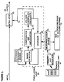
- a satellite video signal receiver modulator stage 12 incorporating the principles of the invention is shown in the block diagram of Figure 1.
- a received video signal after processing by an input processor 14, is modulated onto a carrier frequency Fc by modulator 50.
- Modulator 50 receives the carrier frequency from a Phase-locked Loop (PLL) network 20 and provides an RF modulated output signal to a television receiver 52.
- the PLL output carrier frequency Fc is determined by a microprocessor 15 and by a reference frequency provided by a source 45.
- Microprocessor 15 selects the channel that is used as the modulator channel by controlling the carrier frequency Fc that is output by PLL 20.
- Microprocessor 15 selects the modulator channel in response to inputs received from an operator usable switch network 10 and an operator menu control and display network 16.
- the operator may use menu control 16 to select a main (non-default) channel as the modulator channel only when the satellite receiver and the television receiver are compatibly tuned to the same modulator channel frequency so that a valid image is displayed by the television receiver, which displays the menu.
- the operator may select a predetermined (manufacturer set) default channel as the modulator channel using switch network 10.
- the operator in using menu control 16 of the satellite receiver to select the modulator channel sets the modulator output channel frequency Fc for the satellite receiver. This new frequency may be a manufacturer pre-set default channel frequency, or a main non-default channel frequency.
- a problem may arise if the operator forgets the channel, if another operator changes the main channel, or if the main channel is "forgotten” by the system, e.g., in the case of an electrical fault.
- a first recovery mode this may be done by selecting a manufacturer pre-set default channel to override the current modulator channel selection, by means of switch 10, for example.
- a second recovery mode this may be done by recalling a previous main channel selection from memory.
- An operator may use switch network 10 to manually select a predetermined (manufacturer set) default modulator channel without having to scroll option menus (using control 16) displayed by the television receiver.
- An operator may also use switch network 10 without having to obtain a valid television picture display. This is important because both of these actions may be impossible if there is an incompatibility between the satellite receiver and television receiver modulator channel settings. This means that the possibility such an incompatibility caused a television receiver picture loss cannot be eliminated without operator intervention.
- the operator intervenes, under the direction of the operator's instruction manual, by selecting the modulator default channel using switch network 10 as part of a set-up or fault diagnosis procedure. The procedure directs the operator to first select a satellite receiver modulator default channel, and then to select the same channel on the television receiver. By this procedure the operator restores the receiver equipment to a known usable state with both the satellite receiver and television receiver compatibly tuned to the same channel.
- Switch network 10 illustratively comprises three multi-function pushbuttons that are mounted on the satellite receiver unit and are accessible to the operator.
- the operator presses the three pushbuttons of network 10 in a prescribed sequence. Both this prescribed sequence and the actual channel used as the default channel may be disclosed to the operator in the owner's instruction manual, or by printed instruction on the satellite receiver unit itself. More than one default channel may be available for selection using different pushbutton sequences. This improves the likelihood that the operator can select a default channel that is unused in his local broadcast area.
- the operator may prefer to manually select the modulator default channel using switch network 10 if selecting the modulator channel from a displayed menu obtained by using control 16 is more complicated.
- Pushbutton activation of the switches in network 10 is detected by microprocessor 15, which periodically monitors the status of switch network 10.
- the pushbuttons are arranged so that they provide, on activation, a change in the logic state of digital signals which are periodically read by microprocessor 15. Alternatively, for example, these signals may be coupled to the microprocessor interrupt inputs. In this case pushbutton activation interrupts the operation of microprocessor 15 so that microprocessor 15 does not need to periodically read switch network 10.
- Microprocessor 15 both detects and decodes the sequence of pushbutton activation. Upon recognizing a prescribed sequence, microprocessor 15 instructs PLL 20 to output the default channel carrier frequency to the carrier frequency input of modulator 50.
- the default channel setting is stored in non-volatile memory of microprocessor 15. Preferably, the default channel is hard-coded in microprocessor 15 by the manufacturer.
- PLL 20 is a conventional programmable phase locked loop composed of a phase/frequency detector 30, a compensation and amplification network 35, a voltage controlled oscillator (VCO) 40 and a programmable frequency divider 25.
- VCO voltage controlled oscillator
- a logic control value is written by microprocessor 15 into a register in programmable divider 25 to determine the PLL output carrier frequency Fc provided by VCO 40 to modulator 50.
- the PLL output frequency is divided by programmable divider 25 and compared by detector 30 to a frequency reference from source 45.
- the division performed by divider 25 is determined by the logic control value written to a register within divider 25 by microprocessor 15.
- An output voltage of detector 30, representing the phase/frequency error, is amplified and compensated by unit 35 to provide an oscillation frequency control signal to VCO 40.
- the amplification and compensation provided by unit 35 ensures the stability of the PLL.
- the compensation may be in the form of filtering as known.
- microprocessor 15 monitors the status of output signals produced by menu control 16 in response to operator selection of a modulator main channel. Microprocessor 15 responds to these signals by causing PLL 20 to generate an output carrier signal Fc at the frequency of the modulator main channel selected by the operator using menu control 16.
- the VCO 40 output frequency determined by microprocessor 15 is the carrier frequency used by modulator 50.
- Modulator 50 frequency modulates this carrier frequency with the input signal from source 14 containing the video information to be output by the satellite receiver.
- the output signal from modulator 50 is a frequency modulated RF signal containing the desired video information. This output signal is provided to other units as required, such as a television receiver.
- the carrier frequency of the satellite receiver output signal is the default channel frequency selected by microprocessor 15 via switch network 10, or the main channel frequency selected via menu control 16.
- Switch network 10 of Figure 1 may exhibit a variety of configurations in addition to multi-function pushbuttons as discussed.
- network 10 may use a single dedicated switch with several fixed positions. One of these positions may select a manufacturer set default channel as an alternative to a modulator main channel selected from a displayed menu using control 16.
- a second position in a recovery mode, may cause the satellite receiver to revert to a main channel previously selected by the operator using the selection menus.
- a third position may cause the satellite receiver to automatically select a manufacturer pre-set default channel.
- Other switch positions may provide additional manufacture set default channels. This result would also be useful when the operator has forgotten the previously set modulator main channel.
- the default channel provided would be known to the operator from the instruction manual, or it may be displayed, for example, by means of a display panel 70 shown in Figure 2.
- FIG. 2 Another embodiment of the invention is shown in Figure 2.
- the default channel selection and the main channel selection are both accomplished using a remote control unit 60.
- a manufacturer pre-set default channel is selected using switch network 10
- modulator main channels are selected by the operator using menu display control 16.
- the system of Figure 2 includes viewer operated infra-red remote control unit 60, a receiver infra-red remote control interface network 65 and a representation of a satellite receiver display panel 70 which are not present in the system of Figure 1.
- Other elements in Figure 2 correspond to similarly labeled elements in Figure 1.
- Units 60 and 65 are of conventional infra-red type design but could also be a different design type such as units that operate at radio frequency, for example.
- the operator selects a main channel or a manufacturer pre-set default channel by, for example, pressing a designated pushbutton or a sequence of pushbuttons on remote control unit 60.
- a resulting infra-red output signal from unit 60 is transmitted to infra-red receiver interface network 65.
- Network 65 decodes the infra-red signal and provides a resultant decoded command signal to microprocessor 15.
- microprocessor 15 programs PLL 20 to output the selected channel carrier frequency. This is performed in the manner described in connection with the embodiment of Figure 1.
- modulator 50 frequency modulates the selected channel carrier frequency with the video information of the input signal.
- Additional pushbuttons or sequences thereof may provide first and second recovery modes respectively automatically engaging a manufacturer default channel, or recalling from memory a previously selected modulator main channel, as discussed in connection with Figure 1.
- the number of the channel selected by microprocessor 15 as the satellite receiver output modulator channel is displayed by satellite receiver display panel 70.
- This visual indication may be a standard Light Emitting Diode (LED) type of display and is driven by microprocessor 15.
- LED Light Emitting Diode
- LCDs Liquid Crystal Displays
- the operator on viewing the display, can immediately determine if there is an incompatibility between the satellite receiver modulator output channel frequency and the channel to which an associated television receiver is tuned. If an incompatibility exists, the operator can use remote unit 60 to select a default channel or a main channel as the modulator channel.
- both main channel and default channel modulator frequencies are selected from the UHF broadcast television band to facilitate channel tuning.
- channel selections may be from different bands in accordance with the requirements of a particular system.
- the disclosed modulator output channel selection system may be used in a VCR as well as in a satellite receiver.
Abstract
Description
- This invention is related to the field of video signal receiving apparatus. In particular, the invention concerns a system for selecting an RF modulator output channel in a direct broadcast satellite receiver, for example.
- Video signal receivers such as direct broadcast satellite receivers and video cassette recorders (VCRs) provide video output signals as Radio Frequency (RF) modulated signals to a television receiver, for example. The carrier frequency selected for this RF modulation in the United States, for example, is usually the broadcast channel 3 or channel 4 cable television (CATV) carrier frequency. Selection of one of these channels is typically accomplished by means of a user operated manual switch. This switch is usually located on the VCR or satellite receiver unit. The operator using a satellite receiver, for example, is typically directed by an instruction manual to select the broadcast channel (3 or 4) that is not used in the operator's local broadcast area. The operator then selects that same channel on the television receiver to ensure that the television receiver is tuned to the same carrier frequency as the satellite receiver RF output.
- A problem may arise when both channel 3 and channel 4 are unavailable for use as modulator channels by the satellite receiver. This may occur if one channel is in use in a particular local broadcast area, and the other channel is unusable/unavailable due to being corrupted by broadcast interference. In another situation, both channels 3 and 4 may already be in use. This may occur, for example, if the output of the satellite receiver is being combined with a cable television signal. In such case one channel may carry a television signal and the other channel may already be used as a modulator channel. In these situations the operator may be forced to use a television signal broadcast channel as the satellite receiver output modulator channel. As a result, the operator loses a television signal broadcast channel since any television signal being transmitted on that channel prior to modulation will be lost in the modulation process.
- To address these situations, some advanced video receivers use continuously adjustable RF modulators instead of channel 3/4 switches. The adjustable RF modulators allow an unused television channel in the channel 1 - 125 band, for example, to be used as the modulator channel. Although the satellite receiver may be manufacturer pre-set to a certain modulator channel, for
example channel 65, when delivered to the consumer/operator, the operator is able to select any of the available channels as the modulator channel. The operator may do this by means of a particular menu selection using a remote control device. - Operator adjustable modulators may present problems. One problem that may arise is incompatibility between a video receiver (satellite receiver or VCR) modulator output channel and the channel to which a television receiver, receiving the modulator output, is tuned. Such an incompatibility may occur if the operator is unaware of the modulator channel setting of the video receiver, and sets the television receiver to a different channel. Then, the television receiver tuner will not be set to the same carrier frequency as the video receiver RF output signal. This situation may occur if the operator forgets which modulator channel he has selected, if he inadvertently changes the modulator channel, or the modulator channel is changed without his knowledge. These situations are more likely to arise with video receivers that use operator adjustable modulators with a wide, continuously adjustable frequency selection range. In such a case there is a greater opportunity for an operator to erroneously set a modulator channel, or to forget a previously selected modulator channel. The operator may then set the television receiver to an incompatible channel. As a result the television tuner will not be set to the carrier frequency of the video receiver modulator, and the television receiver will not display a valid picture. The operator may interpret this result as an equipment failure.
- The inventor has recognized that it is advantageous for an operator to be able to directly set the adjustable modulator of a video receiver (such as a satellite receiver or VCR) to a desired channel. The inventor has also recognized that it is desirable for one or more manufacturer pre-set modulator channels (default channels) to be individually directly selectable by the operator.
- In a system in accordance with the principles of the present invention, a video receiver such as a satellite video receiver, provides output signals to a television receiver. The video receiver also includes apparatus for operator selection of the modulator output channel frequency of the satellite receiver. The apparatus permits the operator to select a modulator main channel chosen by the operator, or alternatively a manufacturer pre-set default channel. The apparatus also permits the operator to automatically engage a manufacturer pre-set default channel in a recovery mode, e.g., if a chosen main channel is forgotten. In another recovery mode, the operator may automatically recall from memory a previously set modulator main channel.
- In accordance with a feature of the invention, the operator may select the default channel from a range of discretely selectable channels. In accordance with another feature of the invention, a visual display indication of the selected modulator channel is provided.
- In the drawing:
- Figure 1 shows an adjustable RF modulator for a video receiver according to the invention.
- Figure 2 shows an adjustable RF modulator for a video receiver according to the invention involving a remote control unit and a modulator channel display.
- A satellite video signal
receiver modulator stage 12 incorporating the principles of the invention is shown in the block diagram of Figure 1. A received video signal, after processing by aninput processor 14, is modulated onto a carrier frequency Fc bymodulator 50.Modulator 50 receives the carrier frequency from a Phase-locked Loop (PLL)network 20 and provides an RF modulated output signal to atelevision receiver 52. The PLL output carrier frequency Fc is determined by amicroprocessor 15 and by a reference frequency provided by asource 45.Microprocessor 15 selects the channel that is used as the modulator channel by controlling the carrier frequency Fc that is output byPLL 20.Microprocessor 15 selects the modulator channel in response to inputs received from an operator usable switch network 10 and an operator menu control anddisplay network 16. - The operator may use
menu control 16 to select a main (non-default) channel as the modulator channel only when the satellite receiver and the television receiver are compatibly tuned to the same modulator channel frequency so that a valid image is displayed by the television receiver, which displays the menu. As an alternative to selecting the main channel as the modulatorchannel using control 16, the operator may select a predetermined (manufacturer set) default channel as the modulator channel using switch network 10. The operator in usingmenu control 16 of the satellite receiver to select the modulator channel sets the modulator output channel frequency Fc for the satellite receiver. This new frequency may be a manufacturer pre-set default channel frequency, or a main non-default channel frequency. - If a main channel is chosen, a problem may arise if the operator forgets the channel, if another operator changes the main channel, or if the main channel is "forgotten" by the system, e.g., in the case of an electrical fault. In order to recover from these situations, it is desirable to return the system to a known modulator channel configuration. In a first recovery mode, this may be done by selecting a manufacturer pre-set default channel to override the current modulator channel selection, by means of switch 10, for example. In a second recovery mode, this may be done by recalling a previous main channel selection from memory.
- An operator may use switch network 10 to manually select a predetermined (manufacturer set) default modulator channel without having to scroll option menus (using control 16) displayed by the television receiver. An operator may also use switch network 10 without having to obtain a valid television picture display. This is important because both of these actions may be impossible if there is an incompatibility between the satellite receiver and television receiver modulator channel settings. This means that the possibility such an incompatibility caused a television receiver picture loss cannot be eliminated without operator intervention. The operator intervenes, under the direction of the operator's instruction manual, by selecting the modulator default channel using switch network 10 as part of a set-up or fault diagnosis procedure. The procedure directs the operator to first select a satellite receiver modulator default channel, and then to select the same channel on the television receiver. By this procedure the operator restores the receiver equipment to a known usable state with both the satellite receiver and television receiver compatibly tuned to the same channel.
- Switch network 10 illustratively comprises three multi-function pushbuttons that are mounted on the satellite receiver unit and are accessible to the operator. In order to restore the satellite receiver to a predetermined modulator default channel set by the manufacturer, the operator presses the three pushbuttons of network 10 in a prescribed sequence. Both this prescribed sequence and the actual channel used as the default channel may be disclosed to the operator in the owner's instruction manual, or by printed instruction on the satellite receiver unit itself. More than one default channel may be available for selection using different pushbutton sequences. This improves the likelihood that the operator can select a default channel that is unused in his local broadcast area. The operator may prefer to manually select the modulator default channel using switch network 10 if selecting the modulator channel from a displayed menu obtained by using
control 16 is more complicated. - Pushbutton activation of the switches in network 10 is detected by
microprocessor 15, which periodically monitors the status of switch network 10. The pushbuttons are arranged so that they provide, on activation, a change in the logic state of digital signals which are periodically read bymicroprocessor 15. Alternatively, for example, these signals may be coupled to the microprocessor interrupt inputs. In this case pushbutton activation interrupts the operation ofmicroprocessor 15 so thatmicroprocessor 15 does not need to periodically read switch network 10. -
Microprocessor 15 both detects and decodes the sequence of pushbutton activation. Upon recognizing a prescribed sequence,microprocessor 15 instructsPLL 20 to output the default channel carrier frequency to the carrier frequency input ofmodulator 50. The default channel setting is stored in non-volatile memory ofmicroprocessor 15. Preferably, the default channel is hard-coded inmicroprocessor 15 by the manufacturer.PLL 20 is a conventional programmable phase locked loop composed of a phase/frequency detector 30, a compensation andamplification network 35, a voltage controlled oscillator (VCO) 40 and aprogrammable frequency divider 25. A logic control value is written bymicroprocessor 15 into a register inprogrammable divider 25 to determine the PLL output carrier frequency Fc provided byVCO 40 tomodulator 50. - The PLL output frequency is divided by
programmable divider 25 and compared bydetector 30 to a frequency reference fromsource 45. The division performed bydivider 25 is determined by the logic control value written to a register withindivider 25 bymicroprocessor 15. An output voltage ofdetector 30, representing the phase/frequency error, is amplified and compensated byunit 35 to provide an oscillation frequency control signal toVCO 40. The amplification and compensation provided byunit 35 ensures the stability of the PLL. The compensation may be in the form of filtering as known. - Similarly,
microprocessor 15 monitors the status of output signals produced bymenu control 16 in response to operator selection of a modulator main channel.Microprocessor 15 responds to these signals by causingPLL 20 to generate an output carrier signal Fc at the frequency of the modulator main channel selected by the operator usingmenu control 16. - The
VCO 40 output frequency determined bymicroprocessor 15 is the carrier frequency used bymodulator 50.Modulator 50 frequency modulates this carrier frequency with the input signal fromsource 14 containing the video information to be output by the satellite receiver. The output signal frommodulator 50 is a frequency modulated RF signal containing the desired video information. This output signal is provided to other units as required, such as a television receiver. The carrier frequency of the satellite receiver output signal is the default channel frequency selected bymicroprocessor 15 via switch network 10, or the main channel frequency selected viamenu control 16. - Switch network 10 of Figure 1 may exhibit a variety of configurations in addition to multi-function pushbuttons as discussed. For example, network 10 may use a single dedicated switch with several fixed positions. One of these positions may select a manufacturer set default channel as an alternative to a modulator main channel selected from a displayed
menu using control 16. A second position, in a recovery mode, may cause the satellite receiver to revert to a main channel previously selected by the operator using the selection menus. In another recovery mode, a third position may cause the satellite receiver to automatically select a manufacturer pre-set default channel. Other switch positions may provide additional manufacture set default channels. This result would also be useful when the operator has forgotten the previously set modulator main channel. In this case the default channel provided would be known to the operator from the instruction manual, or it may be displayed, for example, by means of adisplay panel 70 shown in Figure 2. - Another embodiment of the invention is shown in Figure 2. In Figure 2 the default channel selection and the main channel selection are both accomplished using a
remote control unit 60. In Figure 1 in contrast, a manufacturer pre-set default channel is selected using switch network 10, and modulator main channels are selected by the operator usingmenu display control 16. The system of Figure 2 includes viewer operated infra-redremote control unit 60, a receiver infra-red remotecontrol interface network 65 and a representation of a satellitereceiver display panel 70 which are not present in the system of Figure 1. Other elements in Figure 2 correspond to similarly labeled elements in Figure 1.Units - In the embodiment of Figure 2 the operator selects a main channel or a manufacturer pre-set default channel by, for example, pressing a designated pushbutton or a sequence of pushbuttons on
remote control unit 60. A resulting infra-red output signal fromunit 60 is transmitted to infra-redreceiver interface network 65.Network 65 decodes the infra-red signal and provides a resultant decoded command signal tomicroprocessor 15. Upon receipt of this command signal,microprocessor 15programs PLL 20 to output the selected channel carrier frequency. This is performed in the manner described in connection with the embodiment of Figure 1. Finally, also as described in connection with Figure 1,modulator 50 frequency modulates the selected channel carrier frequency with the video information of the input signal. - Additional pushbuttons or sequences thereof may provide first and second recovery modes respectively automatically engaging a manufacturer default channel, or recalling from memory a previously selected modulator main channel, as discussed in connection with Figure 1.
- The number of the channel selected by
microprocessor 15 as the satellite receiver output modulator channel is displayed by satellitereceiver display panel 70. This visual indication may be a standard Light Emitting Diode (LED) type of display and is driven bymicroprocessor 15. However, other types of display devices may also be used, such as Liquid Crystal Displays (LCDs). The operator, on viewing the display, can immediately determine if there is an incompatibility between the satellite receiver modulator output channel frequency and the channel to which an associated television receiver is tuned. If an incompatibility exists, the operator can useremote unit 60 to select a default channel or a main channel as the modulator channel. - If
display 70 is not provided in the Figure 2 embodiment, the operator cannot visually determine that there is an incompatibility between the satellite receiver and television tuner channels. This means, that operator intervention is required to determine whether such an incompatibility exists and is responsible for picture loss on the television receiver. The operator intervenes by selecting the modulator default channel, usingremote control 60, under the instruction of the user's manual. - In the disclosed system, both main channel and default channel modulator frequencies are selected from the UHF broadcast television band to facilitate channel tuning. In other systems, channel selections may be from different bands in accordance with the requirements of a particular system. Also, the disclosed modulator output channel selection system may be used in a VCR as well as in a satellite receiver.
Claims (13)
- A video signal receiver for modulating a carrier with received input information to provide a modulated output signal compatible with a television signal receiver, said video receiver including apparatus characterized by:
means (20,45) for generating channel carriers at carrier frequencies within a band of television channel frequencies, and having a control input and an output for providing a generated channel carrier in response to a control signal applied to said control input;
first user operated means (16,15; 60,65,15) providing a first control signal to said control input of said generating means for manually selecting a generated channel carrier;
second user operated means (16,15; 60,65,15) providing a second control signal to said control input of said generating means for manually selecting a manufacturer preselected available channel carrier as an alternative to said channel carrier selected by said first means; and
means (50), having an input coupled to said output of said generating means, for modulating a generated carrier selected by said first means or a carrier selected by said second means with said received input information to provide said modulated output signal; wherein
said channel carrier selected by said first user operated means is a channel carrier other than said manufacturer preselected available channel carrier. - Apparatus according to claim 1, characterized in that
said first means comprises a controllable switching network, said second means comprises a controllable switching network with selectable conditions, and said first means causing said generating means to provide a channel carrier, irrespective of the condition of said second switching network. - Apparatus according to claim 1 or 2, characterized in that
a representation of said manufacturer preselected channel carrier is stored in non-volatile memory. - Apparatus according to claim 1 or 2, and further characterized by
means for automatically replacing a channel carrier selected by said first means with said manufacturer preselected channel carrier. - Apparatus according to claim 1, characterized in that
said second means further includes multi-function switches. - Apparatus according to claim 5, characterized in that
said multi-function switches require sequential activation for selecting said manufacturer preselected channel carrier by said second means. - Apparatus according to claim 1 or 2, further characterized by
means for providing a visual display indication of an output channel carrier from said generating means. - Apparatus according to claim 1 or 2, characterized in that
said channel carriers respectively selected by said first means and said second means are located in the UHF broadcast television spectrum. - Apparatus according to claim 1 or 2, and further characterized by
means for automatically re-establishing a channel carrier previously selected by said first means by recalling said previously selected channel carrier from memory. - A video signal receiver for modulating a carrier with received input information to provide a modulated output signal compatible with a television signal receiver, said video receiver including apparatus characterized by:
means (20,45) for generating channel carriers at carrier frequencies within a band of television channel frequencies, and having a control input and an output for providing an output channel carrier in response to a control signal applied to said control input;
a user operated selection network (16,15; 60,65,15) providing a first control signal to said control input of said generating means for manually selecting an output channel carrier with a frequency other than a manufacturer preselected channel carrier frequency;
user operated means (10,15; 60,65,15) for automatically re-establishing a channel carrier previously selected by said user operated selection network by recalling said previously selected channel carrier from memory and providing a second control signal to said control input of said generating means to select said output channel carrier; and
means (50) for modulating said output channel carrier with said received input information to provide said modulated output signal. - In a video signal receiver for modulating a carrier with received input information to provide a modulated output signal compatible with a television signal receiver, a method for user selection of an output channel carrier characterized by the steps of:(a) selecting a manufacturer preselected channel carrier from within a band of television carrier frequencies;(b) selecting an alternative channel carrier from within said band of television carrier frequencies, said alternative channel carrier being other than a manufacturer preselected channel carrier; and(c) modulating a channel carrier selected in accordance with steps (a) or (b) with said received video information to produce said compatible output signal.
- A method according to claim 11, further characterized by the step of
replacing automatically an existing channel carrier with said manufacturer preselected channel carrier. - A method according to claim 11 or 12, further characterized by the step of
re-establishing automatically a channel carrier selected in step (b) by recalling said carrier selected in step (b) from memory.
Applications Claiming Priority (2)
| Application Number | Priority Date | Filing Date | Title |
|---|---|---|---|
| US384299 | 1995-02-06 | ||
| US08/384,299 US5541671A (en) | 1995-02-06 | 1995-02-06 | User channel selection control for a video reciever RF modulator |
Publications (2)
| Publication Number | Publication Date |
|---|---|
| EP0725537A2 true EP0725537A2 (en) | 1996-08-07 |
| EP0725537A3 EP0725537A3 (en) | 1998-05-13 |
Family
ID=23516767
Family Applications (1)
| Application Number | Title | Priority Date | Filing Date |
|---|---|---|---|
| EP96100951A Withdrawn EP0725537A3 (en) | 1995-02-06 | 1996-01-24 | Channel selection control for a television receiver modulator |
Country Status (11)
| Country | Link |
|---|---|
| US (2) | US5541671A (en) |
| EP (1) | EP0725537A3 (en) |
| JP (2) | JP4284398B2 (en) |
| KR (1) | KR100395700B1 (en) |
| CN (1) | CN1099189C (en) |
| BR (1) | BR9600296A (en) |
| IN (1) | IN186266B (en) |
| MX (1) | MX9600482A (en) |
| MY (1) | MY111920A (en) |
| SG (1) | SG65543A1 (en) |
| TW (1) | TW329077B (en) |
Cited By (1)
| Publication number | Priority date | Publication date | Assignee | Title |
|---|---|---|---|---|
| EP1026892A1 (en) * | 1999-02-03 | 2000-08-09 | Pace Micro Technology PLC | Vacant broadcast channel searching system |
Families Citing this family (24)
| Publication number | Priority date | Publication date | Assignee | Title |
|---|---|---|---|---|
| US5541671A (en) * | 1995-02-06 | 1996-07-30 | Thomson Consumer Electronics Inc. | User channel selection control for a video reciever RF modulator |
| CA2678640C (en) * | 1996-03-15 | 2012-08-07 | E Guide, Inc. | Method and apparatus for displaying television programs and electronic program guide (epg) |
| JPH10106166A (en) * | 1996-09-30 | 1998-04-24 | Toshiba Corp | Reproducing device and reproducing method |
| US5923386A (en) * | 1997-09-29 | 1999-07-13 | Zenith Electronics Corporation | VCR channel set up for non standard tuning environments |
| US6118497A (en) * | 1998-03-11 | 2000-09-12 | Thomson Consumer Electronics, Inc. | Interactive selection system for a video decoder modulator channel |
| US6567132B1 (en) * | 1999-03-10 | 2003-05-20 | General Instruments Corp. | Upconverter for a television signal headend distribution center handling analog and digital signals and method of making and using the same |
| KR100641094B1 (en) * | 1999-03-18 | 2006-11-02 | 엘지전자 주식회사 | Interface apparatus between digital vcr and satellite broadcasting receiver |
| US6433830B1 (en) * | 1999-06-14 | 2002-08-13 | General Instrument Corporation | Off-air phase lock technique |
| JP3668065B2 (en) * | 1999-08-30 | 2005-07-06 | 三洋電機株式会社 | Video recording / playback device with tuner |
| KR100466077B1 (en) | 2002-02-19 | 2005-01-13 | 삼성전기주식회사 | Radio frequency modulator having c/l delay compensation function, and set-top-box using that |
| US8490129B2 (en) | 2003-01-31 | 2013-07-16 | Qwest Communications International Inc. | Methods, systems and apparatus for selectively distributing urgent public information |
| US7921443B2 (en) | 2003-01-31 | 2011-04-05 | Qwest Communications International, Inc. | Systems and methods for providing video and data services to a customer premises |
| US8713617B2 (en) | 2003-01-31 | 2014-04-29 | Qwest Communications International Inc. | Systems and methods for providing television signals using a network interface device |
| US20040163126A1 (en) * | 2003-01-31 | 2004-08-19 | Qwest Communications International Inc. | Methods and apparatus for delivering a computer data stream to a video appliance with a network interface device |
| US7793003B2 (en) * | 2003-01-31 | 2010-09-07 | Qwest Communications International Inc | Systems and methods for integrating microservers with a network interface device |
| US10142023B2 (en) | 2003-01-31 | 2018-11-27 | Centurylink Intellectual Property Llc | Antenna system and methods for wireless optical network termination |
| US20040227578A1 (en) * | 2003-05-14 | 2004-11-18 | Miikka Hamalainen | Acoustic resonance-based frequency synthesizer using at least one bulk acoustic wave (BAW) or thin film bulk acoustic wave (FBAR) device |
| US8112449B2 (en) | 2003-08-01 | 2012-02-07 | Qwest Communications International Inc. | Systems and methods for implementing a content object access point |
| US8821285B2 (en) | 2003-11-03 | 2014-09-02 | Intel Corporation | Gaming interface techniques for media centers |
| CN100377579C (en) * | 2004-11-19 | 2008-03-26 | 厦门华侨电子股份有限公司 | TV-set frequency channel presetting method |
| US7546374B2 (en) | 2005-08-05 | 2009-06-09 | Global Serv Inc. | Methods and arrangements for managing and maintaining a switch environment |
| US7689704B2 (en) | 2005-08-05 | 2010-03-30 | Global Serv Inc. | Methods and arrangements for managing automated switching |
| FR2891968B1 (en) * | 2005-10-12 | 2008-01-18 | Valeo Electronique Sys Liaison | COMMUNICATION SYSTEM BETWEEN A VIDEO IMAGE ACQUISITION UNIT AND A BOARD COMPUTER FOR A MOTOR VEHICLE |
| KR101767343B1 (en) | 2016-09-19 | 2017-08-10 | 서규선 | Earthquake Warning and Evacuation Broadcasting System |
Citations (4)
| Publication number | Priority date | Publication date | Assignee | Title |
|---|---|---|---|---|
| US4336555A (en) * | 1980-09-15 | 1982-06-22 | Rca Corporation | Video accessory having channel identifier |
| US4717970A (en) * | 1984-06-21 | 1988-01-05 | Zenith Electronics Corporation | Video system with programmable VCR |
| US5029015A (en) * | 1988-01-22 | 1991-07-02 | U.S. Philips Corporation | Video signal recorder/player devices |
| WO1993017522A1 (en) * | 1992-02-20 | 1993-09-02 | Motorola Inc. | A modulator circuit |
Family Cites Families (6)
| Publication number | Priority date | Publication date | Assignee | Title |
|---|---|---|---|---|
| SE8406489L (en) * | 1984-12-19 | 1986-06-20 | Nordspace Ab | television reception |
| US5227881A (en) * | 1991-11-04 | 1993-07-13 | Eastman Kodak Company | Electronic adjustment of video system parameters |
| KR950016005U (en) * | 1993-11-27 | 1995-06-19 | Video channel expansion system | |
| KR0140960B1 (en) * | 1993-12-18 | 1998-07-15 | 구자홍 | Automatic tv channel selecting device for viewing vcr programs |
| KR960020363A (en) * | 1994-11-14 | 1996-06-17 | 김광호 | TV's V-Channel Automatic Switching Device |
| US5541671A (en) * | 1995-02-06 | 1996-07-30 | Thomson Consumer Electronics Inc. | User channel selection control for a video reciever RF modulator |
-
1995
- 1995-02-06 US US08/384,299 patent/US5541671A/en not_active Expired - Lifetime
- 1995-10-27 TW TW084111347A patent/TW329077B/en not_active IP Right Cessation
-
1996
- 1996-01-09 IN IN1862CA1996 patent/IN186266B/en unknown
- 1996-01-13 MY MYPI96000129A patent/MY111920A/en unknown
- 1996-01-24 EP EP96100951A patent/EP0725537A3/en not_active Withdrawn
- 1996-01-31 SG SG1996000725A patent/SG65543A1/en unknown
- 1996-01-31 BR BR9600296A patent/BR9600296A/en not_active Application Discontinuation
- 1996-02-02 JP JP01784596A patent/JP4284398B2/en not_active Expired - Lifetime
- 1996-02-02 MX MX9600482A patent/MX9600482A/en unknown
- 1996-02-05 CN CN96103527A patent/CN1099189C/en not_active Expired - Lifetime
- 1996-02-06 KR KR1019960002749A patent/KR100395700B1/en not_active IP Right Cessation
- 1996-03-20 US US08/618,956 patent/US5748261A/en not_active Expired - Lifetime
-
2006
- 2006-04-18 JP JP2006114919A patent/JP4377388B2/en not_active Expired - Lifetime
Patent Citations (4)
| Publication number | Priority date | Publication date | Assignee | Title |
|---|---|---|---|---|
| US4336555A (en) * | 1980-09-15 | 1982-06-22 | Rca Corporation | Video accessory having channel identifier |
| US4717970A (en) * | 1984-06-21 | 1988-01-05 | Zenith Electronics Corporation | Video system with programmable VCR |
| US5029015A (en) * | 1988-01-22 | 1991-07-02 | U.S. Philips Corporation | Video signal recorder/player devices |
| WO1993017522A1 (en) * | 1992-02-20 | 1993-09-02 | Motorola Inc. | A modulator circuit |
Cited By (1)
| Publication number | Priority date | Publication date | Assignee | Title |
|---|---|---|---|---|
| EP1026892A1 (en) * | 1999-02-03 | 2000-08-09 | Pace Micro Technology PLC | Vacant broadcast channel searching system |
Also Published As
| Publication number | Publication date |
|---|---|
| EP0725537A3 (en) | 1998-05-13 |
| CN1143295A (en) | 1997-02-19 |
| US5748261A (en) | 1998-05-05 |
| JP4377388B2 (en) | 2009-12-02 |
| KR960033121A (en) | 1996-09-17 |
| KR100395700B1 (en) | 2003-11-20 |
| CN1099189C (en) | 2003-01-15 |
| MX9600482A (en) | 1997-06-28 |
| SG65543A1 (en) | 1999-06-22 |
| US5541671A (en) | 1996-07-30 |
| MY111920A (en) | 2001-02-28 |
| JPH08251493A (en) | 1996-09-27 |
| IN186266B (en) | 2001-07-21 |
| BR9600296A (en) | 1997-12-23 |
| JP2006211723A (en) | 2006-08-10 |
| JP4284398B2 (en) | 2009-06-24 |
| TW329077B (en) | 1998-04-01 |
Similar Documents
| Publication | Publication Date | Title |
|---|---|---|
| US5748261A (en) | Video receiver user channel selection control of an RF modulator | |
| KR100739405B1 (en) | Method and apparatus for providing feedback during programming of a television apparatus | |
| US20020021373A1 (en) | Signal receiving apparatus, remote controller, signal receiving system, and apparatus to be controlled | |
| EP1062803B1 (en) | Interactive selection system for a video decoder modulator channel | |
| US6836297B2 (en) | Video signal selecting device | |
| MXPA00008798A (en) | Interactive selection system for a video decoder modulator channel | |
| JPH1132276A (en) | Television receiver | |
| JPH099368A (en) | Remote commander, remote commander system and remote commanding method | |
| KR19980049137U (en) | VSI system with channel change protection | |
| KR0140371B1 (en) | Television broadcasting mode display method | |
| KR200187568Y1 (en) | Automatic switching apparatus of satellite broadcast and game device for television | |
| JPS5899026A (en) | Remote control channel selecting system | |
| JPH0759168A (en) | Satellite broadcast receiver | |
| KR20010059927A (en) | method for realizing multiscreen in TV | |
| KR19990009166U (en) | V's receive broadcast output automatic switching device | |
| JPH0983466A (en) | Wired broadcast system | |
| JPS63257321A (en) | Channel presetting method | |
| KR19990052938A (en) | How to Unlock O'Sial's V'Sial | |
| KR19980017883A (en) | Easy reservation recording method | |
| KR20000044050A (en) | Method for switching-over dedicated channel of vcr | |
| KR20000008255A (en) | Reservation recording method of a cable tv reception broadcasting | |
| KR19980064716U (en) | VSI System with Electronic Calculator | |
| JPS63235887A (en) | Electronic apparatus | |
| KR19990031975A (en) | Vision protection method with PI's PI function | |
| JPH02274011A (en) | Channel selector |
Legal Events
| Date | Code | Title | Description |
|---|---|---|---|
| PUAI | Public reference made under article 153(3) epc to a published international application that has entered the european phase |
Free format text: ORIGINAL CODE: 0009012 |
|
| AK | Designated contracting states |
Kind code of ref document: A2 Designated state(s): DE FR GB IE |
|
| PUAL | Search report despatched |
Free format text: ORIGINAL CODE: 0009013 |
|
| AK | Designated contracting states |
Kind code of ref document: A3 Designated state(s): DE FR GB IE |
|
| 17P | Request for examination filed |
Effective date: 19981031 |
|
| 17Q | First examination report despatched |
Effective date: 19981215 |
|
| STAA | Information on the status of an ep patent application or granted ep patent |
Free format text: STATUS: THE APPLICATION IS DEEMED TO BE WITHDRAWN |
|
| 18D | Application deemed to be withdrawn |
Effective date: 20010301 |