EP0723381B2 - Device for hearing assistance - Google Patents
Device for hearing assistance Download PDFInfo
- Publication number
- EP0723381B2 EP0723381B2 EP94120781A EP94120781A EP0723381B2 EP 0723381 B2 EP0723381 B2 EP 0723381B2 EP 94120781 A EP94120781 A EP 94120781A EP 94120781 A EP94120781 A EP 94120781A EP 0723381 B2 EP0723381 B2 EP 0723381B2
- Authority
- EP
- European Patent Office
- Prior art keywords
- control unit
- ear
- region
- microphones
- area
- Prior art date
- Legal status (The legal status is an assumption and is not a legal conclusion. Google has not performed a legal analysis and makes no representation as to the accuracy of the status listed.)
- Expired - Lifetime
Links
Images


Classifications
-
- H—ELECTRICITY
- H04—ELECTRIC COMMUNICATION TECHNIQUE
- H04R—LOUDSPEAKERS, MICROPHONES, GRAMOPHONE PICK-UPS OR LIKE ACOUSTIC ELECTROMECHANICAL TRANSDUCERS; DEAF-AID SETS; PUBLIC ADDRESS SYSTEMS
- H04R25/00—Deaf-aid sets, i.e. electro-acoustic or electro-mechanical hearing aids; Electric tinnitus maskers providing an auditory perception
- H04R25/04—Deaf-aid sets, i.e. electro-acoustic or electro-mechanical hearing aids; Electric tinnitus maskers providing an auditory perception comprising pocket amplifiers
-
- H—ELECTRICITY
- H04—ELECTRIC COMMUNICATION TECHNIQUE
- H04R—LOUDSPEAKERS, MICROPHONES, GRAMOPHONE PICK-UPS OR LIKE ACOUSTIC ELECTROMECHANICAL TRANSDUCERS; DEAF-AID SETS; PUBLIC ADDRESS SYSTEMS
- H04R25/00—Deaf-aid sets, i.e. electro-acoustic or electro-mechanical hearing aids; Electric tinnitus maskers providing an auditory perception
- H04R25/55—Deaf-aid sets, i.e. electro-acoustic or electro-mechanical hearing aids; Electric tinnitus maskers providing an auditory perception using an external connection, either wireless or wired
- H04R25/552—Binaural
-
- H—ELECTRICITY
- H04—ELECTRIC COMMUNICATION TECHNIQUE
- H04R—LOUDSPEAKERS, MICROPHONES, GRAMOPHONE PICK-UPS OR LIKE ACOUSTIC ELECTROMECHANICAL TRANSDUCERS; DEAF-AID SETS; PUBLIC ADDRESS SYSTEMS
- H04R25/00—Deaf-aid sets, i.e. electro-acoustic or electro-mechanical hearing aids; Electric tinnitus maskers providing an auditory perception
- H04R25/40—Arrangements for obtaining a desired directivity characteristic
- H04R25/407—Circuits for combining signals of a plurality of transducers
-
- H—ELECTRICITY
- H04—ELECTRIC COMMUNICATION TECHNIQUE
- H04R—LOUDSPEAKERS, MICROPHONES, GRAMOPHONE PICK-UPS OR LIKE ACOUSTIC ELECTROMECHANICAL TRANSDUCERS; DEAF-AID SETS; PUBLIC ADDRESS SYSTEMS
- H04R25/00—Deaf-aid sets, i.e. electro-acoustic or electro-mechanical hearing aids; Electric tinnitus maskers providing an auditory perception
- H04R25/60—Mounting or interconnection of hearing aid parts, e.g. inside tips, housings or to ossicles
- H04R25/602—Mounting or interconnection of hearing aid parts, e.g. inside tips, housings or to ossicles of batteries
Definitions
- the invention relates to a device for hearing support, which has two microphones with one Control unit are coupled and the control unit with Feed input signals and at which the control unit at least one output signal to at least one Transmission element transmitted and at which the control unit spatially separated from the microphones is, as well as with the microphones in the area of a human ear can be arranged in ear housings are recorded and in which the ear housings each are provided with a transmitter with a receiver communicates in the area of the control unit, and in the area of at least one of the ear housings one of the transmission elements is arranged, the is provided with a receiver with a transmitter communicates in the area of the control unit as well with an analyzer in the area of the control unit Evaluation of the signals of the microphones is arranged.
- a device is already known from FR-A-2 651 634 known for hearing support, in which a microphone with a control unit is coupled and in which the control unit spatially separated from the microphone is.
- the microphone is in the area of an ear casing arranged that is recordable by a human ear is. Communication takes place via a Receiver and a transmitter and in the area of the control unit is an analyzer for evaluating the signals arranged the microphone.
- DE-A-2 406 218 discloses a device for Hearing support is described with two microphones be used. However, both microphones are arranged in a common ear housing. At least one of the microphones has a directional characteristic on. The signals from the two microphones are in the Processed area of a control unit.
- a microphone is printed in the area of an ear housing arranged, which is arranged with a spatially separate Control unit Via one transmitter and one Receiver communicates.
- a comparable device is from DE-OS 35 12 999 known. Through a different orientation of the microphones and a subsequent subtraction the output signals of the microphones from each other it should enable one in all listening directions to eliminate effective ambient noise.
- the Transmission element is designed here as a loudspeaker.
- DE-OS 35 08 830 it is known locally separated from a speaker in an ear case is arranged, which in turn by one human ear recordable or behind can be arranged in a human ear, in the area of a separate control unit, a microphone, an amplifier and arrange a power source.
- a wireless transmission of signals to one Hearing aid is described in DE-OS 30 32 311.
- signals to be transmitted wirelessly for example from a telecommunications system or provided a radio become.
- Another construction in which a spatial Separation of loudspeaker and control unit provided is described in DE-OS 28 44 979.
- the microphone is also in the area of the control unit arranged.
- DE 31 00 135 C2 is already a device known for hearing support, the two microphones has, which are coupled to a control unit.
- the Microphones feed the control unit with input signals.
- the control unit transmits at least one output signal to at least one transmission element.
- the control unit is spatially separated from the Microphones arranged and each of the microphones is from accommodated in a housing.
- One of the transmission elements is arranged in the area of an ear housing.
- There is a comparator in the area of the control unit provided for evaluating the signals of the microphones, which is the output power of the control unit Modification adapted to sound reproduction.
- DE 30 27 384 describes a method for forming described by sound signals, in which the unnatural Directional sensations through the forming regarding the directional impressions in the natural Hearing sensations better approximated hearing sensations can be converted.
- DE 41 01 933 A 1 describes a control unit for directional microphone signals for the generation of virtual Directional characteristics with adjustable main reception direction.
- the output signal is multiplied by Evaluation of the input signals with control parameters educated.
- DE 35 30 205 Al already has a microphone system known with variable directional characteristic, the one Row of microphones that are equidistant are arranged to each other.
- the directional pattern is due to a special row-like arrangement of the microphones and by using a weighting network realized with weighting factors.
- DE 29 28 845 A1 describes an audiovocal integration device described, which has a microphone, that through a special device with a vibrator is coupled, the vibrations on the skin of a user can muster. About a corresponding one Control takes place a coordination of the acoustic as well as the sensitive signal transmission.
- Devices for hearing support are known at which all components in the field of human Arranged ear, or in which at one spatial separation of components in the area only one loudspeaker is provided for the ear and the other components, especially the amplifier and the microphones, in a spatially separated area control unit arranged by the loudspeaker are provided. It is not with these devices satisfactorily possible for one user a replica of the natural sense of hearing to enable spatial hearing and at the same time a Suppression of noise.
- the object of the present invention is a To construct a device of the type mentioned in the introduction, that both ensures good acoustic quality is also perceived as pleasant Ease of use is realized.
- this object is achieved by that the analyzer the output power of the control unit for adaptation to spatial sound reproduction modified that output signals of the microphones be evaluated comparably by the analyzer and that in the area of at least one of the transmission elements an ear amplifier is arranged, and that the control unit for manual inputs has an operating unit.
- a Useful noise- interference noise selection process carried out be there in the presence of hearing loss enables the person concerned, by moving the Head or equivalent setting in the area the control unit is regarded as dominant Perceive sound source predominantly. It is there regardless of whether the acoustic signals are Speech, music or typical noise. In particular, it is possible with a monoaurally supplied To reproduce a hearing sensation for the hearing impaired, that is largely a normal spatial hearing corresponds. This results from the fact that the hearing impaired by moving his head and through the appropriate signal evaluation Can locate sound source.
- a transmission path is provided. This can be wireless.
- the transmitter with the Receivers are connected via a line.
- the comparator with an envelope correlator is provided.
- Another improvement in directional hearing can also be done in that the comparator with a Time correlator is provided.
- control unit takes place in that the control unit in the area of a wearable on a wrist Bracelet is arranged.
- the ear amplifier As well further components is provided that in the area at least one of the ear housings arranged an ear battery is.
- a level limiter is provided.
- a sufficient intensity of that from the control unit emitted signals can take place that in the area of the control unit a main amplifier is provided.
- Adequate sound energy in the area of Ear casing is provided in that in the area at least one of the transmission elements is an ear amplifier is arranged.
- the device for hearing support is according to the embodiment in Fig. 1 from a control unit (1), two microphones (2,3) and ear housings (4,5), in which the microphones (2,3) are installed and the have a shape that allows the earhousing (4,5) in the area of an auricle or one Arrange ear canal of a human ear.
- Each of the microphones (2, 3) is in the area of the ear housing (4,5) assigned to a transmitter (6), each with one Receiver (7) in the area of the control unit (1) communicates.
- a transmission element (8) arranged with each one also in the area of the ear housing (4,5) arranged receiver (9) is connected.
- the Receivers (9) receive their signals from transmitters (10), which are arranged in the area of the control unit (1).
- For the immediate supply of the transmission elements (8) are ear amplifiers in the area of the ear housing (4,5) (11) arranged.
- the control unit (1) is equipped with a comparator (12) provided an evaluation of the signals from the microphones (2,3) relative to each other enables a spatial Listen to replicate and suppress noise.
- a comparator (12) provided an evaluation of the signals from the microphones (2,3) relative to each other enables a spatial Listen to replicate and suppress noise.
- the transmission elements are formed (8) as a speaker is provided, for limitation the radiated in the area of the speakers Sound energy in the area of the control unit (1) level limiter (13) to be arranged.
- the control unit (1) has a main battery (14).
- the ear casing (4,5) can be used for energy supply the components with ear batteries (15).
- the transmission elements (8) can also be used as electrodes be trained that electrically on the auditory nerves act.
- the detailed structure of the control unit (1) results from Fig. 2.
- the overall function is of a Controller (16) monitors.
- a Controller (16) monitors As additional assemblies are in addition to the level limiters already mentioned (13), the comparator (12), the main battery (14) and the receivers (7) and the transmitters (10), a service unit (17), a display (18) a directional microphone (19) and a frequency filter (20) are provided.
- a level adjustment takes place via a main amplifier (34).
- the controller (16) predefined tables are accessed through which a setting of the frequency filter (20) and the level limiter (13) is possible.
- FIG. 3 A schematic diagram to illustrate one spatial hearing is shown in Fig. 3.
- An individual (21) has his ears (22) here in one direction of hearing (23) aligned.
- side sound radiation (24) a sound impulse strikes the Ears (22).
- Sound pressure profiles (25) thus have a temporally offset in the area of the ears (22) Course and different levels.
- Frontal sound radiation (26) are the sound pressure profiles (25) in the area of the ears (22), however, essentially congruent in time.
- Fig. 4 is particular thought of the control unit (1) in the area of a Arrange bracelet (27), which in turn in Fixed area of a human wrist (28) can be. In confined spaces it is also possible to use some of the components of the Control unit (1) in the area of links of the bracelet (27) to be installed.
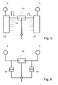
- a circuit variant for an envelope correlation is a circuit variant for an envelope correlation and in Fig. 6 a circuit variant shown for a time correlation.
- the frequency separator (29) has individual frequency ranges assigned separate outputs (30) on. For example, it is possible to use a separator outlet the frequency range from 0 - 0.5 kHz, the next Separator output (30) the frequency range of 0.5 - 1 kHz and the other frequency ranges additional Assign separator outputs (30).
- Envelope correlators (31) are used to analyze the Determination of sound pressure level differences between the microphones (2,3).
- a time correlator (32) is used and a Coupling takes place according to a bypass Attenuators (33).
- Both the envelope correlation and the time correlation can be technically analog or digital will be realized. In particular, it is thought an improvement by combining the two methods to enable sound detection. For Ensure adequate detection of Loudness differences between the left and right Ear it is appropriate to use the correlation method only to be activated when there is frontal radiation (26) is present.
- Control unit (1) it is possible to make a change make the settings made, without changing the position of the microphones (2, 3). This means that not within the Ears (22) arranged ear housing (4,5) accessed must become.
- the directional microphone (19) can by a corresponding movement of a forearm of the individual (21) can be positioned.
- control unit (17) in the area of Control unit (1) it is possible to have a predefinable gain of signals from one of the microphones (2, 3). This allows the user to avoid his Head towards the desired sound source rotate. It is also possible with the help of the control unit (17) to adjust the volume, make a microphone selection or Specify sound group program selection.
- the transmitters (6, 10) for example, as output amplifiers and the receivers (7, 9) as input amplifiers realized.
- a wireless connection can be used.
- a radio connection can be used to suppress interference for example certain transmission frequencies be reserved, so it is also possible alternative To provide transmission channels or alternative To maintain modulation frequencies.
- a wireless one Transmission can also take place via IR or HF signals.
- the device can have different applications be fed. With the one already described Using it as a hearing aid it is possible to record a sound Via the microphones (2,3) in the area of the ear housing (4,5). Alternatively, it is possible to use one Sound recording via a in the area of the bracelet (27) arranged microphone to perform. Further Sound recordings can be made externally, for example via a telephone, a radio, a surveillance microphone, Consumer electronics devices, personal computers or alarm detector.
- the signals are processed in the area of the central unit, which is the comparator (12), the level limiter (13), the frequency filter (20) and a corresponding amplifier (34) can have.
- the comparison of the time and level difference between the spectral components of the left and Right microphone signal optionally leads to noise suppression.
- the signal components with time and Level difference not increased. A user of the device is thus able to primarily perceive the sound source, to which he has the front of his head turns.
- the microphones (2, 3) are inside the Ohmuscheln arranged, so are those coming from behind Signals attenuated by the auricle. Recognizes the comparator (12) that almost exclusively signals with There is no time and level difference sound suppression made. For example, if a conversation partner is on the left or right side of the user sits and talks and a conversation partner sitting opposite is silent. When recording sound over that in the area of the bracelet (27) arranged microphone or for sound recordings External audio units do not suppress side noise carried out.
- the central unit and the components within the Ear case (4,5) are in the area of the ear case (4,5) no amplifier and no power supply required. If necessary, a preamplifier can be used be useful for sending.
- the sound is reproduced via at least one of the loudspeakers in the area of the ear housing (4.5). If the side noise suppression at one Inserted inner ear implant, so the side sound suppressed Signal fed to the processor that the controls implanted electrodes. Through the electrodes there is a charm of the Hömerven.
- a microphone in the area of the central unit For applications outside the area of application hearing aids are picked up by a microphone in the area of the central unit. Through signal processing in the area of the central unit can be optional noise suppression can be carried out. The sound is reproduced externally, for example via the same device, a telephone, a radio, a personal computer or an alarm device.
- an external sound recording can, for example, over a telephone, a radio security microphone, a consumer electronics device, a personal computer or an alarm device respectively.
- the signal processing in the central unit can optionally with a speech recognition or Speech generation.
- a Sound reproduction takes place with an external sound recording via at least one speaker in one Ear case (4,5). Sound reproduction is also conceivable via a loudspeaker in the area of Central unit to perform.
- the signal transmission between the microphones (2,3) in the area of the ear housing (4,5) and the central unit can be done both analog and digital. It is also possible to use analog signal processing or digitally. According to the respective Boundary conditions is also a mixed analog and digital processing possible. According to each selected processing sequence will be analog-to-digital conversions or digital-to-analog conversions carried out. With a partial analog version is particularly thought of reinforcement operations to be carried out analogously.
- the decomposition can be done, for example, by Fast Fourier Transformations (FFT) or through the use of filter banks respectively. After performing the separation in the frequency bands it is possible to suppress side noise, a frequency response correction, a dynamic compression, a dehumidification or other procedures to improve speech intelligibility perform.
- FFT Fast Fourier Transformations
- Dynamic compression takes into account that a dynamic range for normal hearing within from 0 dB to 130 dB. In the event of hearing loss are noises until a certain one Perceived threshold of volume. This is also frequency dependent. The dynamic range is restricted. E.g. a linear gain of all noises, so should be amplitudes above the discomfort threshold, for example above a limit of 130 dB, be cut off. It is therefore cheaper to Maintain amplitude course and the limited Compress dynamic range.
- the dehumidification possible to provide an anti-feedback.
- the signal digitized it can be determined whether hall influences and there can be a minimization of the Hall effect can be performed. Digitization enables an evaluation of the signals. About that it can also be determined whether by the amplifier an additional reinforcement of the already reinforced Signals has been performed. By a time delay of the signal, it is possible to occur To suppress feedback effects.
- Improving speech intelligibility can be performed by special algorithms that lead to an increase in sharpness of speech.
- All the measures described above for influencing the signal can be used as algorithms for editing be formulated on a digital computer. It is advisable the algorithms each one specific Spectral component to increase or decrease the dynamic value assign. After a corresponding split of the signal into the spectral components and the application one of the algorithms described Recombination to a resulting overall signal. This can be done, for example, by inverse Fast Fourier Transformation or one of the initial filtering appropriate inverse filtering is done.
Landscapes
- Engineering & Computer Science (AREA)
- Acoustics & Sound (AREA)
- Neurosurgery (AREA)
- Otolaryngology (AREA)
- Physics & Mathematics (AREA)
- General Health & Medical Sciences (AREA)
- Health & Medical Sciences (AREA)
- Signal Processing (AREA)
- Computer Networks & Wireless Communication (AREA)
- Circuit For Audible Band Transducer (AREA)
- Measurement And Recording Of Electrical Phenomena And Electrical Characteristics Of The Living Body (AREA)
- Measuring Pulse, Heart Rate, Blood Pressure Or Blood Flow (AREA)
- Orthopedics, Nursing, And Contraception (AREA)
- Headphones And Earphones (AREA)
- Telephone Function (AREA)
Abstract
Description
Die Erfindung betrifft eine Vorrichtung zur Hörunterstützung, die zwei Mikrofone aufweist, die mit einer Steuereinheit gekoppelt sind und die Steuereinheit mit Eingangssignalen speisen und bei der die Steuereinheit mindestens ein Ausgangssignal zu mindestens einem Übertragungselement übermittelt und bei der die Steuereinheit räumlich getrennt von den Mikrofonen angeordnet ist, sowie bei der die Mikrofone von im Bereich eines menschlichen Ohres anordbaren Ohrgehäusen aufgenommen sind und bei der die Ohrgehäuse jeweils mit einem Sender versehen sind, der mit einem Empfänger im Bereich der Steuereinheit kommuniziert, und bei der im Bereich mindestens eines der Ohrgehäuse eines der Übertragungselemente angeordnet ist, das mit einem Empfänger versehen ist, der mit einem Sender im Bereich der Steuereinheit kommuniziert sowie bei der im Bereich der Steuereinheit ein Analysator zur Auswertung der Signale der Mikrofone angeordnet ist.The invention relates to a device for hearing support, which has two microphones with one Control unit are coupled and the control unit with Feed input signals and at which the control unit at least one output signal to at least one Transmission element transmitted and at which the control unit spatially separated from the microphones is, as well as with the microphones in the area of a human ear can be arranged in ear housings are recorded and in which the ear housings each are provided with a transmitter with a receiver communicates in the area of the control unit, and in the area of at least one of the ear housings one of the transmission elements is arranged, the is provided with a receiver with a transmitter communicates in the area of the control unit as well with an analyzer in the area of the control unit Evaluation of the signals of the microphones is arranged.
Aus der FR-A-2 651 634 ist bereits eine Vorrichtung zur Hörunterstützung bekannt, bei der ein Mikrofon mit einer Steuereinheit gekoppelt ist und bei der die Steuereinheit räumlich getrennt vom Mikrofon angeordnet ist. Das Mikrofon wird im Bereich eines Ohrgehäuses angeordnet, das von einem menschlichen Ohr aufnehmbar ist. Eine Kommunikation erfolgt Über einen Empfänger und einen Sender und im Bereich der Steuereinheit ist ein Analysator zur Auswertung der Signale des Mikrofons angeordnet.A device is already known from FR-A-2 651 634 known for hearing support, in which a microphone with a control unit is coupled and in which the control unit spatially separated from the microphone is. The microphone is in the area of an ear casing arranged that is recordable by a human ear is. Communication takes place via a Receiver and a transmitter and in the area of the control unit is an analyzer for evaluating the signals arranged the microphone.
In der DE-A-2 406 218 wird eine Vorrichtung zur Hörunterstützung beschrieben, bei der bereits zwei Mikrofone verwendet werden. Beide Mikrofone werden jedoch in einem gemeinsam Ohrgehäuse angeordnet. Mindestens eines der Mikrofone weist eine Richtcharakteristik auf. Die Signale der beiden Mikrofone werden im Bereich einer Steuereinheit verarbeitet.DE-A-2 406 218 discloses a device for Hearing support is described with two microphones be used. However, both microphones are arranged in a common ear housing. At least one of the microphones has a directional characteristic on. The signals from the two microphones are in the Processed area of a control unit.
Aus der WO-A-89 04 583 ist eine weitere Vorrichtung zur Hörunterstützung bekannt. Gemäß dieser Druckschrift wird im Bereich eines Ohrgehäuses ein Mikrofon angeordnet, das mit einer räumlich getrennt angeordneten Steuereinheit Über einen Sender und einen Empfänger kommuniziert.Another device is known from WO-A-89 04 583 known for hearing support. According to this A microphone is printed in the area of an ear housing arranged, which is arranged with a spatially separate Control unit Via one transmitter and one Receiver communicates.
Eine vergleichbare Vorrichtung ist aus der DE-OS 35 12 999 bekannt. Durch eine unterschiedliche Orientierung der Mikrofone und eine anschließende Subtraktion der Ausgangssignale der Mikrofone voneinander soll es ermöglicht werden, ein in allen Hörrichtungen wirksames Umgebungsgeräusch zu eliminieren. Das Übertragungselement ist hier als Lautsprecher ausgebildet.A comparable device is from DE-OS 35 12 999 known. Through a different orientation of the microphones and a subsequent subtraction the output signals of the microphones from each other it should enable one in all listening directions to eliminate effective ambient noise. The Transmission element is designed here as a loudspeaker.
Aus der DE-OS 35 08 830 ist es bekannt, örtlich getrennt von einem Lautsprecher, der in einem Ohrgehäuse angeordnet ist, das seinerseits von einem menschlichen Ohr aufnehmbar beziehungsweise hinter einem menschlichen Ohr anordbar ist, im Bereich einer separaten Steuereinheit, ein Mikrofon, einen Verstärker und eine Stromquelle anzuordnen. Durch diese Vorrichtung ist es möglich, das im Bereich des menschlichen Ohres anzuordnende Bauteil relativ leicht zu konstruieren. Eine drahtlose Übertragung von Signalen zu einem Hörgerät wird in der DE-OS 30 32 311 beschrieben. Hierbei ist an drahtlos zu übertragende Signale gedacht, die beispielsweise von einer Telekommunikationsanlage oder einem Rundfunkgerät bereitgestellt werden. Eine weitere Konstruktion, bei der eine räumliche Trennung von Lautsprecher und Steuereinheit vorgesehen ist, wird in der DE-OS 28 44 979 beschrieben. Auch hier ist das Mikrofon im Bereich der Steuereinheit angeordnet.From DE-OS 35 08 830 it is known locally separated from a speaker in an ear case is arranged, which in turn by one human ear recordable or behind can be arranged in a human ear, in the area of a separate control unit, a microphone, an amplifier and arrange a power source. Through this device is it possible in the human realm Component ear to be arranged relatively easy to construct. A wireless transmission of signals to one Hearing aid is described in DE-OS 30 32 311. Here is thought of signals to be transmitted wirelessly, for example from a telecommunications system or provided a radio become. Another construction in which a spatial Separation of loudspeaker and control unit provided is described in DE-OS 28 44 979. The microphone is also in the area of the control unit arranged.
Aus der DE 31 00 135 C2 ist bereits eine Vorrichtung zur Hörunterstützung bekannt, die zwei Mikrofone aufweist, die mit einer Steuereinheit gekoppelt sind. Die Mikrofone speisen die Steuereinheit mit Eingangssignalen. Die Steuereinheit übermittelt mindestens ein Ausgangssignal zu mindestens einem Übertragungselement. Die Steuereinheit ist räumlich getrennt von den Mikrofonen angeordnet und jedes der Mikrofone ist von einem Gehäuse aufgenommen. Eines der Übertragungselemente ist im Bereich eines Ohrgehäuses angeordnet. Im Bereich der Steuereinheit ist ein Vergleicher zur Auswertung der Signale der Mikrofone vorgesehen, der die Ausgangsleistung der Steuereinheit zur Anpassung an eine Schallwiedergabe modifiziert.DE 31 00 135 C2 is already a device known for hearing support, the two microphones has, which are coupled to a control unit. The Microphones feed the control unit with input signals. The control unit transmits at least one output signal to at least one transmission element. The control unit is spatially separated from the Microphones arranged and each of the microphones is from accommodated in a housing. One of the transmission elements is arranged in the area of an ear housing. There is a comparator in the area of the control unit provided for evaluating the signals of the microphones, which is the output power of the control unit Modification adapted to sound reproduction.
In der DE 30 27 384 wird ein Verfahren zur Umformung von Schallsignalen beschrieben, bei dem unnatürliche Richtungsempfindungen durch das Umformen bezüglich der Richtungseindrücke in den natürlichen Hörempfindungen besser angenäherte Hörempfindungen umgewandelt werden können.DE 30 27 384 describes a method for forming described by sound signals, in which the unnatural Directional sensations through the forming regarding the directional impressions in the natural Hearing sensations better approximated hearing sensations can be converted.
Die DE 41 01 933 A 1 beschreibt ein Steuergerät für Richtmikrofonsignale zur Erzeugung von virtuellen Richtcharakteristiken mit einstellbarer Hauptempfangsrichtung. Das Ausgangssignal wird durch multiplikative Bewertung der Eingangssignale mit Steuerparametern gebildet.DE 41 01 933 A 1 describes a control unit for directional microphone signals for the generation of virtual Directional characteristics with adjustable main reception direction. The output signal is multiplied by Evaluation of the input signals with control parameters educated.
Aus der DE 35 30 205 Al ist bereits eine Mikrofonanlage mit variabler Richtcharakteristik bekannt, die eine Reihe von Mikrofonen aufweist, die in gleichem Abstand zueinander angeordnet sind. Die Richtcharakteristik wird durch eine spezielle reihenartige Anordnung der Mikrofone sowie durch Einsatz eines Gewichtungsnetzwerkes mit Gewichtungsfaktoren realisiert.DE 35 30 205 Al already has a microphone system known with variable directional characteristic, the one Row of microphones that are equidistant are arranged to each other. The directional pattern is due to a special row-like arrangement of the microphones and by using a weighting network realized with weighting factors.
In der DE 29 28 845 Al wird ein audiovokales Integrationsgerät beschrieben, das ein Mikrofon aufweist, das über eine spezielle Einrichtung mit einem Vibrator gekoppelt ist, der Schwingungen auf die Haut eines Benutzers aufbringen kann. Über eine entsprechende Steuerung erfolgt eine Koordinierung der akustischen sowie der sensitiven Signalübertragung.DE 29 28 845 A1 describes an audiovocal integration device described, which has a microphone, that through a special device with a vibrator is coupled, the vibrations on the skin of a user can muster. About a corresponding one Control takes place a coordination of the acoustic as well as the sensitive signal transmission.
Gemäß diesem Stand der Technik sind somit entweder Vorrichtungen zur Hörunterstützung bekannt, bei denen sämtliche Bauelemente im Bereich des menschlichen Ohres angeordnet werden, oder bei denen bei einer räumlichen Trennung von Bauelementen im Bereich des Ohres lediglich ein Lautsprecher vorgesehen ist und die weiteren Bauelemente, insbesondere der Verstärker und die Mikrofone, im Bereich einer räumlich getrennt vom Lautsprecher angeordneten Steuereinheit vorgesehen sind. Mit diesen Vorrichtungen ist es nicht in zufriedenstellender Weise möglich, einem Benutzer ein dem natürlichen Hörempfinden nachgebildetes räumliches Hören zu ermöglichen und gleichzeitig eine Unterdrückung von Störgeräuschen vorzunehmen.According to this state of the art are either Devices for hearing support are known at which all components in the field of human Arranged ear, or in which at one spatial separation of components in the area only one loudspeaker is provided for the ear and the other components, especially the amplifier and the microphones, in a spatially separated area control unit arranged by the loudspeaker are provided. It is not with these devices satisfactorily possible for one user a replica of the natural sense of hearing to enable spatial hearing and at the same time a Suppression of noise.
Aufgabe der vorliegenden Erfindung ist es, eine Vorrichtung der einleitend genannten Art derart zu konstruieren, daß sowohl eine gute akustische Qualität gewährleistet ist als auch ein als angenehm empfundener Benutzungskomfort realisiert ist.The object of the present invention is a To construct a device of the type mentioned in the introduction, that both ensures good acoustic quality is also perceived as pleasant Ease of use is realized.
Diese Aufgabe wird erfindungsgemäß dadurch gelöst, daß der Analysator die Ausgangsleistung der Steuereinheit zur Anpassung an eine räumliche Schallwiedergabe modifiziert, daß Ausgangsignale der Mikrofone vergleichend vom Analysator ausgewertet werden und daß im Bereich mindestens eines der Übertragungselemente ein Ohrverstärker angeordnet ist, und daß die Steuereinheit für manuelle Eingaben eine Bedienungseinheit aufweist.According to the invention, this object is achieved by that the analyzer the output power of the control unit for adaptation to spatial sound reproduction modified that output signals of the microphones be evaluated comparably by the analyzer and that in the area of at least one of the transmission elements an ear amplifier is arranged, and that the control unit for manual inputs has an operating unit.
Mit Hilfe der Anordnung der Mikrofone innerhalb der Ohrgehäuse wird eine Ausrichtung des Schallempfanges in unterschiedliche Richtungen entsprechend üblichen Hörgewohnheiten durchgeführt. Insbesondere wird es hierdurch ermöglicht, Störgeräusche durch gezieltes Richtungshören zu kompensieren. Es ist möglich, eine zentrale Auswertung der Signale der einzelnen Mikrofone durchzuführen.With the help of the arrangement of the microphones within the Ear housing becomes an orientation of sound reception in different directions according to usual Listening habits performed. In particular this makes it possible to reduce noise through targeted Compensate directional hearing. It is possible, a central evaluation of the signals of the individual Perform microphones.
Mit Hilfe des Vergleichers kann beispielsweise ein Nutzschall- Störschall- Selektionsverfahren durchgeführt werden, das es bei Vorliegen einer Hörschädigung dem Betroffenen ermöglicht, durch eine Bewegung des Kopfes oder eine entsprechende Einstellung im Bereich der Steuereinheit eine als dominierend angesehene Schallquelle überwiegend wahrzunehmen. Es ist dabei gleichgültig, ob es sich bei den akustischen Signalen um Sprache, Musik oder typische Störgeräusche handelt. Insbesondere ist es möglich, bei einem monoaural versorgten Hörgeschädigten ein Hörempfinden nachzubilden, das weitgehend einem normalen räumlichen Hören entspricht. Dies resultiert daraus, daß der Hörgeschädigte durch eine Bewegung seines Kopfes und durch die entsprechende Signalauswertung eine Schallquelle orten kann.With the help of the comparator, for example, a Useful noise- interference noise selection process carried out be there in the presence of hearing loss enables the person concerned, by moving the Head or equivalent setting in the area the control unit is regarded as dominant Perceive sound source predominantly. It is there regardless of whether the acoustic signals are Speech, music or typical noise. In particular, it is possible with a monoaurally supplied To reproduce a hearing sensation for the hearing impaired, that is largely a normal spatial hearing corresponds. This results from the fact that the hearing impaired by moving his head and through the appropriate signal evaluation Can locate sound source.
Durch die Anordnung der Mikrofone in Ohrgehäusen, die in das Ohr eingesetzt werden können und durch die Verlagerung aller weiteren Elemente in den Bereich der räumlich getrennt angeordneten Steuereinheit wird eine optisch kaum wahrnehmbare Hörhilfe realisiert, die bei hoher Klangqualität keine optischen Einschränkungen des Erscheinungsbildes des mit der Vorrichtung ausgestatteten Menschen verursacht.Due to the arrangement of the microphones in ear housings, that can be inserted into the ear and through the relocation of all other elements to the area of the spatially separated control unit realizes a hearing aid that is barely perceptible to the eye with high sound quality no visual restrictions the appearance of the device equipped people.
Ein besonders hoher Benutzungskomfort wird dadurch bereitgestellt, daß zur Datenübertragung von den Sendern zu den Empfängern eine Übertragungsstrecke vorgesehen ist. Diese kann drahtlos ausgebildet sein.This makes it particularly easy to use provided that for data transmission from the Transmitters to the receivers a transmission path is provided. This can be wireless.
Zur Gewährleistung einer hohen Übertragungssicherheit ist es auch möglich, daß die Sender mit den Empfängern über eine Leitung verbunden sind.To ensure high transmission security it is also possible that the transmitter with the Receivers are connected via a line.
Zur Unterstützung des Richtungshörens wird vorgeschlagen, daß der Vergleicher mit einem Hüllkurvenkorrelator versehen ist.To support directional hearing, it is proposed that the comparator with an envelope correlator is provided.
Eine weitere Verbesserung des Richtungshörens kann auch dadurch erfolgen, daß der Vergleicher mit einem Zeitkorrelator versehen ist.Another improvement in directional hearing can also be done in that the comparator with a Time correlator is provided.
Eine ergonomisch besonders zweckmäßige Anordnung der Steuereinheit erfolgt dadurch, daß die Steuereinheit im Bereich eines an einem Handgelenk tragbaren Armbandes angeordnet ist.An ergonomically particularly useful arrangement the control unit takes place in that the control unit in the area of a wearable on a wrist Bracelet is arranged.
Eine weitere Variation zum Richtungshören wird dadurch bereitgestellt, daß im Bereich der Steuereinheit ein Richtmikrofon angeordnet ist.Another variation on directional listening is thereby provided that in the area of the control unit a directional microphone is arranged.
Zur Energieversorgung der Ohrverstärker sowie weiterer Bauteile ist vorgesehen, daß im Bereich mindestens eines der Ohrgehäuse eine Ohrbatterie angeordnet ist.To power the ear amplifier as well further components is provided that in the area at least one of the ear housings arranged an ear battery is.
Zur Vermeidung unzweckmäßiger Lautstärken wird vorgeschlagen, daß im Bereich der Steuereinheit für mindestens einen Übertragungskanal ein Pegelbegrenzer vorgesehen ist.To avoid inappropriate volume proposed that in the area of the control unit for at least one transmission channel a level limiter is provided.
Eine ausreichende Intensität der von derSteuereinheit ausgesendeten Signale kann dadurch erfolgen, daß im Bereich der Steuereinheit ein Hauptverstärker vorgesehen ist.A sufficient intensity of that from the control unit emitted signals can take place that in the area of the control unit a main amplifier is provided.
Eine ausreichende Schallenergie im Bereich der Ohrgehäuse wird dadurch bereitgestellt, daß im Bereich mindestens eines der Übertragungselemente ein Ohrverstärker angeordnet ist.Adequate sound energy in the area of Ear casing is provided in that in the area at least one of the transmission elements is an ear amplifier is arranged.
In der Zeichnung sind Ausführungsbeispiele der Erfindung schematisch dargestellt. Es zeigen:
- Fig. 1
- ein Blockschaltbild mit einer Anordnung mit zwei Mikrofonen sowie örtlich getrennt angeordneter Steuereinheit, bei derdie übertragung leitungsgebunden erfolgt,
- Fig. 2
- eine vergrößerte Darstellung der Steuereinheit gemäß Fig. 1,
- Fig. 3
- eine Prinzipdarstellung zur Veranschaulichung eines räumlichen Hörvorganges,
- Fig. 4
- eine im Bereich eines Armbandes angeordnete Steuereinheit,
- Fig. 5
- eine Prinzipdarstellung zur Veranschaulichung einer Hüllkurvenkorrelation und
- Fig. 6
- eine Prinzipdarstellung zur Veranschaulichung einer Zeitkorrelation.
- Fig. 1
- 2 shows a block diagram with an arrangement with two microphones and a control unit which is arranged at a separate location, in which the transmission is conducted in a line-bound manner,
- Fig. 2
- 2 shows an enlarged illustration of the control unit according to FIG. 1,
- Fig. 3
- a schematic diagram to illustrate a spatial hearing process,
- Fig. 4
- a control unit arranged in the area of a bracelet,
- Fig. 5
- a schematic diagram to illustrate an envelope correlation and
- Fig. 6
- a schematic diagram to illustrate a time correlation.
Die Vorrichtung zur Hörunterstützung besteht gemäß der Ausführungsform in Fig. 1 aus einer Steuereinheit (1), zwei Mikrofonen (2,3) sowie Ohrgehäusen (4,5), in die die Mikrofone (2,3) eingebaut sind und die eine Formgebung aufweisen, die es ermöglicht, die Ohrgehäuse (4,5) im Bereich einer Ohrmuschel bzw. eines Gehörganges eines menschlichen Ohres anzuordnen. Jedem der Mikrofone (2,3) ist im Bereich der Ohrgehäuse (4,5) ein Sender (6) zugeordnet, der mit jeweils einem Empfänger (7) im Bereich der Steuereinheit (1) kommuniziert. Gemäß der Ausführungsform in Fig. 1 ist zusätzlich im Bereich von jedem der Ohrgehäuse (4,5) ein Übertragungselement (8) angeordnet, das mit jeweils einem ebenfalls im Bereich des Ohrgehäuses (4,5) angeordneten Empfänger (9) verbunden ist. Die Empfänger (9) erhalten ihre Signale von Sendern (10), die im Bereich der Steuereinheit (1) angeordnet sind. Zur unmittelbaren Versorgung der Übertragungselemente (8) sind im Bereich des Ohrgehäuses (4,5) Ohrverstärker (11) angeordnet.The device for hearing support is according to the embodiment in Fig. 1 from a control unit (1), two microphones (2,3) and ear housings (4,5), in which the microphones (2,3) are installed and the have a shape that allows the earhousing (4,5) in the area of an auricle or one Arrange ear canal of a human ear. Each of the microphones (2, 3) is in the area of the ear housing (4,5) assigned to a transmitter (6), each with one Receiver (7) in the area of the control unit (1) communicates. According to the embodiment in FIG. 1 additionally in the area of each of the ear housings (4,5) a transmission element (8) arranged with each one also in the area of the ear housing (4,5) arranged receiver (9) is connected. The Receivers (9) receive their signals from transmitters (10), which are arranged in the area of the control unit (1). For the immediate supply of the transmission elements (8) are ear amplifiers in the area of the ear housing (4,5) (11) arranged.
Die Steuereinheit (1) ist mit einem Vergleicher (12) versehen, der eine Auswertung der Signale der Mikrofone (2,3) relativ zueinander ermöglicht, um ein räumliches Hören nachzubilden und Störgeräusche zu unterdrücken. Bei einer Ausbildung der Übertragungselemente (8) als Lautsprecher ist vorgesehen, zur Begrenzung der im Bereich der Lautsprecher abgestrahlten Schallenergie im Bereich der Steuereinheit (1) Pegelbegrenzer (13) anzuordnen. Zur Energieversorgung weist die Steuereinheit (1) eine Hauptbatterie (14) auf. Die Ohrgehäuse (4,5) können zur Energieversorgung der Bauelemente mit Ohrbatterien (15) versehen sein. Die Übertragungselemente (8) können auch als Elektroden ausgebildet sein, die elektrisch auf die Hörnerven einwirken.The control unit (1) is equipped with a comparator (12) provided an evaluation of the signals from the microphones (2,3) relative to each other enables a spatial Listen to replicate and suppress noise. When the transmission elements are formed (8) as a speaker is provided, for limitation the radiated in the area of the speakers Sound energy in the area of the control unit (1) level limiter (13) to be arranged. For energy supply the control unit (1) has a main battery (14). The ear casing (4,5) can be used for energy supply the components with ear batteries (15). The transmission elements (8) can also be used as electrodes be trained that electrically on the auditory nerves act.
Der detaillierte Aufbau der Steuereinheit (1) ergibt sich aus Fig. 2. Die Gesamtfunktion wird von einem Controller (16) überwacht. Als weitere Baugruppen sind zusätzlich zu den bereits erwähnten Pegelbegrenzern (13), dem Vergleicher (12), der Hauptbatterie (14) sowie den Empfängern (7) und den Sendern (10), eine dienungseinheit (17), eine Anzeige (18) ein Richtmikrofon (19) sowie ein Frequenzfilter (20) vorgesehen. Eine Pegelanpassung erfolgt Ober einen Hauptverstärker (34). Bei einer Klangbildwahl kann über den Controller (16) auf vordefinierte Tabellen zugegriffen werden, durch die eine Einstellung der Frequenzfilter (20) und der Pegelbegrenzer (13) möglich ist.The detailed structure of the control unit (1) results from Fig. 2. The overall function is of a Controller (16) monitors. As additional assemblies are in addition to the level limiters already mentioned (13), the comparator (12), the main battery (14) and the receivers (7) and the transmitters (10), a service unit (17), a display (18) a directional microphone (19) and a frequency filter (20) are provided. A level adjustment takes place via a main amplifier (34). When selecting a sound pattern, the controller (16) predefined tables are accessed through which a setting of the frequency filter (20) and the level limiter (13) is possible.
Eine Prinzipskizze zur Veranschaulichung eines räumlichen Hörens ist in Fig. 3 wiedergegeben. Ein Individuum (21) hat hier seine Ohren (22) in eine hörrichtung (23) ausgerichtet. Bei einer Seitenschalleinstrahlung (24) trifft ein Schallimpuls zeitlich versetzt auf die Ohren (22) auf. Schalldruckverläufe (25) haben somit im Bereich der Ohren (22) einen zeitlich zueinanderversetzten Verlauf und unterschiedliche Pegel. Bei einer Frontalschalleinstrahlung (26) sind die Schalldruckverläufe (25) im Bereich der Ohren (22) hingegen im wesentlichen zeitlich deckungsgleich.A schematic diagram to illustrate one spatial hearing is shown in Fig. 3. An individual (21) has his ears (22) here in one direction of hearing (23) aligned. With side sound radiation (24) a sound impulse strikes the Ears (22). Sound pressure profiles (25) thus have a temporally offset in the area of the ears (22) Course and different levels. At a Frontal sound radiation (26) are the sound pressure profiles (25) in the area of the ears (22), however, essentially congruent in time.
Gemäß der Ausführungsform in Fig. 4 ist insbesondere daran gedacht, die Steuereinheit (1) im Bereich eines Armbandes (27) anzuordnen, das seinerseits im Bereich eines menschlichen Handgelenkes (28) befestigt werden kann. Bei beengten räumlichen Verhältnissen ist es auch möglich, einen Teil der Bauelemente der Steuereinheit (1) im Bereich von Gliedern des Armbandes (27) zu montieren.According to the embodiment in Fig. 4 is particular thought of the control unit (1) in the area of a Arrange bracelet (27), which in turn in Fixed area of a human wrist (28) can be. In confined spaces it is also possible to use some of the components of the Control unit (1) in the area of links of the bracelet (27) to be installed.
Zur Verdeutlichung der Funktionsweise des Vergleichers (12) sind in Fig. 5 eine Schaltungsvariante für eine Hüllkurvenkorrelation und in Fig. 6 eine Schaltungsvariante für eine Zeitkorrelation dargestellt. Bei der Ausführungsform gemäß Fig. 5 sind die Mikrofone (2,3) jeweils mit einem Frequenzseparator (29) verbunden. Der Frequenzseparator (29) weist einzelnen Frequenzbereichen zugeordnete separate Ausgänge (30) auf. Es ist beispielsweise möglich, einen Separatorausgang dem Frequenzbereich von 0 - 0,5 kHz, den nächsten Separatorausgang (30) dem Frequenzbereich von 0,5 - 1 kHz und die weiteren Frequenzbereiche zusätzlichen Separatorausgängen (30) zuzuordnen. Mit Hilfe von Hüllkurvenkorrelatoren (31) erfolgt eine Analyse zur Ermittlung von Schalldruckpegeldifferenzen zwischen den Mikrofonen (2,3). Tritt eine derartige Schalldruckpegeldifferenz in einem der Frequenzbereiche auf, so wird nur der schwächere Signalanteil zum Gesamtsignal addiert. Hierbei wird ausgenutzt, daß seitlich einfallende Schallwellen das der Schallquelle abgewandte Ohr bzw. das zugeordnete Mikrofon (2,3) mit einer Pegeldifferenz sowie einer Zeitdifferenz erreichen. Prinzipiell ist es zweckmäßig, sowohl die Pegeldifferenz gemäß der Variante in Fig. 5 als auch die Zeitdifferenz gemäß der Variante in Fig. 6 auszunutzen.To illustrate how the comparator works (12) are a circuit variant for an envelope correlation and in Fig. 6 a circuit variant shown for a time correlation. At 5 are the microphones (2,3) each connected to a frequency separator (29). The frequency separator (29) has individual frequency ranges assigned separate outputs (30) on. For example, it is possible to use a separator outlet the frequency range from 0 - 0.5 kHz, the next Separator output (30) the frequency range of 0.5 - 1 kHz and the other frequency ranges additional Assign separator outputs (30). With help Envelope correlators (31) are used to analyze the Determination of sound pressure level differences between the microphones (2,3). Such a sound pressure level difference occurs in one of the frequency ranges, so only the weaker signal component becomes the overall signal added. This takes advantage of the fact that laterally incident Sound waves facing away from the sound source Ear or the assigned microphone (2,3) with a level difference as well as a time difference. In principle it is appropriate to both the level difference according 5 as well as the time difference according to to take advantage of the variant in FIG. 6.
Bei der Durchführung der Zeitkorrelation gemäß Fig. 6 wird ein Zeitkorrelator (32) verwendet und eine Kopplung erfolgt entsprechend einem Bypaß über Dämpfungsglieder (33).When performing the time correlation according to Fig. 6, a time correlator (32) is used and a Coupling takes place according to a bypass Attenuators (33).
Sowohl die Hüllkurvenkorrelation als auch die Zeitkorrelation können schaltungstechnisch analog oder digital realisiert werden. Insbesondere ist daran gedacht, durch eine Kombination der beiden Verfahren eine Verbesserung der Schallerkennung zu ermöglichen. Zur Gewährleistung einer ausreichenden Erkennung von Lautheitsunterschieden zwischen dem linken und rechten Ohr ist es zweckmäßig, die Korrelationsverfahren nur dann zu aktivieren, wenn eine Frontalschalleinstrahlung (26) vorliegt.Both the envelope correlation and the time correlation can be technically analog or digital will be realized. In particular, it is thought an improvement by combining the two methods to enable sound detection. For Ensure adequate detection of Loudness differences between the left and right Ear it is appropriate to use the correlation method only to be activated when there is frontal radiation (26) is present.
Mit Hilfe der im Bereich des Handgelenkes (28) getragenen Steuereinheit (1) ist es möglich, eine Veränderung der vorgenommenen Einstellungen vorzunehmen, ohne die Mikrofone (2,3) in ihrer Position zu verändern. Dies bedeutet, daß nicht auf die innerhalb der Ohren (22) angeordneten Ohrgehäuse (4,5) zugegriffen werden muß. Das Richtmikrofon (19) kann durch eine entsprechende Bewegung eines Unterarmes des Individuums (21) positioniert werden.With the help of those worn in the area of the wrist (28) Control unit (1) it is possible to make a change make the settings made, without changing the position of the microphones (2, 3). This means that not within the Ears (22) arranged ear housing (4,5) accessed must become. The directional microphone (19) can by a corresponding movement of a forearm of the individual (21) can be positioned.
Zusätzlich können externe Audioeingänge und Audioausgänge realisiert werden. Mit Hilfe dieser Zusatzeinrichtungen ist es möglich, Warnsignale oder Telefonsignale zu erzeugen, zu senden, zu empfangen und zu hören.In addition, external audio inputs and audio outputs will be realized. With the help of these additional devices it is possible to get warning signals or phone signals to generate, send, receive and to Listen.
Durch die Bedienungseinheit (17) im Bereich der Steuereinheit (1) ist es möglich, eine vorgebbare Verstärkung von Signalen eines der Mikrofone (2,3) vorzunehmen. Hierdurch kann der Benutzer vermeiden, seinen Kopf in Richtung der gewünschten Schallquelle zu drehen. Darüber hinaus ist es möglich mit Hilfe der Bedienungseinheit (17) eine Lautstärkeregelung vorzunehmen, eine Mikrofonauswahl durchzuführen oder eine KlanggruppenProgrammwahl vorzugeben.By the control unit (17) in the area of Control unit (1) it is possible to have a predefinable gain of signals from one of the microphones (2, 3). This allows the user to avoid his Head towards the desired sound source rotate. It is also possible with the help of the control unit (17) to adjust the volume, make a microphone selection or Specify sound group program selection.
Bei einer drahtgebundenen Kopplung zwischen den Ohrgehäusen (4,5) und der Steuereinheit (1) werden die Sender (6,10) beispielsweise als Ausgangsverstärker und die Empfänger (7,9) als Eingangsverstärker realisiert. Bei einer drahtlosen Verbindung sind standardisierte und damit preiswerte Funkelemente verwendbar. Bei einer Funkverbindung können zur Störungsunterdrückung beispielsweise bestimmte Übertragungsfrequenzen reserviert werden, es so auch möglich, alternative Übertragungskanäle vorzusehen oder alternative Modulationsfrequenzen vorzuhalten. Eine drahtlose Übertragung kann auch über IR- oder HF-Signale erfolgen.With a wired coupling between the earhouses (4,5) and the control unit (1) the transmitters (6, 10), for example, as output amplifiers and the receivers (7, 9) as input amplifiers realized. With a wireless connection are standardized and therefore inexpensive radio elements can be used. A radio connection can be used to suppress interference for example certain transmission frequencies be reserved, so it is also possible alternative To provide transmission channels or alternative To maintain modulation frequencies. A wireless one Transmission can also take place via IR or HF signals.
Die Vorrichtung kann unterschiedlichen Anwendungen zugeführt werden. Bei der bereits beschriebenen Verwendung als Hörgerät ist es möglich, eine Schallaufnahme Über die Mikrofone (2,3) im Bereich der Ohrgehäuse (4,5) durchzuführen. Alternativ ist es möglich, eine Schallaufnahme über ein im Bereich des Armbandes (27) angeordnetes Mikrofon durchzuführen. Weitere Schallaufnahmen können extern erfolgen, beispielsweise über ein Telefon, ein Funkgerät, ein Überwachungsmikrofon, Geräte der Unterhaltungselektronik, Personalcomputer oder Alarmmelder.The device can have different applications be fed. With the one already described Using it as a hearing aid it is possible to record a sound Via the microphones (2,3) in the area of the ear housing (4,5). Alternatively, it is possible to use one Sound recording via a in the area of the bracelet (27) arranged microphone to perform. Further Sound recordings can be made externally, for example via a telephone, a radio, a surveillance microphone, Consumer electronics devices, personal computers or alarm detector.
Bei der Anwendung als Hörgerät erfolgt die Signalverarbeitung im Bereich der Zentraleinheit, die den Vergleicher (12), den Pegelbegrenzer (13), den Frequenzfilter (20) und einen entsprechenden Verstärker (34) aufweisen kann. Der Vergleich der Zeit- und Pegeldifferenz zwischen den Spektratanteilen des linken und rechten Mikrofonsignals führt optional zur schallunterdrückung. Hierbei werden die Signalanteile mit Zeit- und Pegeldifferenz nicht verstärkt. Ein Benutzer der Vorrichtung ist somit in der Lage, primär die Schallquelle wahrzunehmen, zu der er die Vorderseite seines Kopfes wendet.When used as a hearing aid, the signals are processed in the area of the central unit, which is the comparator (12), the level limiter (13), the frequency filter (20) and a corresponding amplifier (34) can have. The comparison of the time and level difference between the spectral components of the left and Right microphone signal optionally leads to noise suppression. The signal components with time and Level difference not increased. A user of the device is thus able to primarily perceive the sound source, to which he has the front of his head turns.
Sind die Mikrofone (2,3) innerhalb der Ohmuscheln angeordnet, so werden die von hinten kommenden Signale durch die Ohrmuschel gedämpft. Erkennt der Vergleicher (12), daß fast ausschließlich Signale mit Zeit- und Pegeldifferenz vorhanden sind, so wird keine schallunterdrückung vorgenommen. Dies erfolgt beispielsweise, wenn ein Gesprächspartner an der linken oder rechten Seite des Benutzers sitzt und redet und ein gegenübersitzender Gesprächspartner schweigt. Bei der Schallaufnahme über das im Bereich des Armbandes (27) angeordnet Mikrofon oder bei Schallaufnahmen von externen Audioeinheiten wird keine Seitenschallunterdrückung durchgeführt.The microphones (2, 3) are inside the Ohmuscheln arranged, so are those coming from behind Signals attenuated by the auricle. Recognizes the comparator (12) that almost exclusively signals with There is no time and level difference sound suppression made. For example, if a conversation partner is on the left or right side of the user sits and talks and a conversation partner sitting opposite is silent. When recording sound over that in the area of the bracelet (27) arranged microphone or for sound recordings External audio units do not suppress side noise carried out.
Bei einer drahtgebundenen Verbindung zwischen der Zentraleinheit und den Bauelementen innerhalb der Ohrgehäuse (4,5) sind im Bereich der Ohrgehäuse (4,5) kein Verstärker und keine Strömversorgung erforderlich. Gegebenenfalls kann allerdings ein Vorverstärker für das Senden zweckmäßig sein. Bei der Verwendung als Hörgerät erfolgt die Schallwiedergabe über mindestens einen der Lautsprecher im Bereich der Ohrgehäuse (4,5). Wird die Seitenschallunterdrückung bei einem Innenohrimplantat eingesetzt, so wird das seitenschallunterdrückte Signal dem Prozessor zugeführt, der die implantierten Elektroden steuert. Durch die Elektroden erfolgt ein Reiz der Hömerven.With a wired connection between the central unit and the components within the Ear case (4,5) are in the area of the ear case (4,5) no amplifier and no power supply required. If necessary, a preamplifier can be used be useful for sending. When using as a hearing aid, the sound is reproduced via at least one of the loudspeakers in the area of the ear housing (4.5). If the side noise suppression at one Inserted inner ear implant, so the side sound suppressed Signal fed to the processor that the controls implanted electrodes. Through the electrodes there is a charm of the Hömerven.
Bei Anwendungen außerhalb des Einsatzbereiches von Hörgeräten erfolgt die Schallaufnahme über ein Mikrofon im Bereich der Zentraleinheit. Durch die Signalverarbeitung im Bereich der Zentraleinheit kann optional eine Störgeräuschunterdrückung durchgeführt werden. Die Schallwiedergabe erfolgt extern, beispielsweise über ein gleiches Gerät, ein Telefon, ein Funkgerät, einen Personalcomputer oder einen Alarmmelder.For applications outside the area of application hearing aids are picked up by a microphone in the area of the central unit. Through signal processing in the area of the central unit can be optional noise suppression can be carried out. The sound is reproduced externally, for example via the same device, a telephone, a radio, a personal computer or an alarm device.
Ebenfalls ist es möglich, bei derartigen Anwendungen eine externe Schallaufnahme vorzusehen. Dies kann beispielsweise über ein Telefon, ein Funkgerät, ein wachungsmikrofon, ein Gerät der Unterhaltungselektronik, einen Personalcomputer oder einen Alarmmelder erfolgen. Die Signalverarbeitung in der Zentraleinheit kann optional auch mit einer Spracherkennung bzw. einer Spracherzeugung ausgestattet werden. Eine Schallwiedergabe erfolgt bei einer externen Schallaufnahme über mindestens einen Lautsprecher in einem Ohrgehäuse (4,5). Ebenfalls ist es denkbar, die Schallwiedergabe über einen Lautsprecher im Bereich der Zentraleinheit durchzuführen.It is also possible in such applications to provide an external sound recording. This can, for example, over a telephone, a radio security microphone, a consumer electronics device, a personal computer or an alarm device respectively. The signal processing in the central unit can optionally with a speech recognition or Speech generation. A Sound reproduction takes place with an external sound recording via at least one speaker in one Ear case (4,5). Sound reproduction is also conceivable via a loudspeaker in the area of Central unit to perform.
Die Signalübertragung zwischen den Mikrofonen (2,3) im Bereich der Ohrgehäuse (4,5) und der Zentraleinheit kann sowohl analog als auch digital erfolgen. Ebenfalls ist es möglich, die Signalverarbeitung analog oder digital zu realisieren. Entsprechend den jeweiligen Randbedingungen ist auch eine gemischte analoge und digitale Verarbeitung möglich. Entsprechend dem jeweils gewählten Verarbeitungsablauf werden Analog-Digital-Wandlungen bzw. Digital-Analog-Wandlungen durchgeführt. Bei einer teilweisen analogen Ausführung ist insbesondere daran gedacht, Verstärkungsoperationen analog durchzuführen.The signal transmission between the microphones (2,3) in the area of the ear housing (4,5) and the central unit can be done both analog and digital. It is also possible to use analog signal processing or digitally. According to the respective Boundary conditions is also a mixed analog and digital processing possible. According to each selected processing sequence will be analog-to-digital conversions or digital-to-analog conversions carried out. With a partial analog version is particularly thought of reinforcement operations to be carried out analogously.
Zur Durchführung einer digitalen Signalverarbeitung werden die von den Mikrofonen (2,3) aufgenommenen Signale digitalisiert und in einzelne Frequenzbänder zerlegt. Hierdurch stehen die einzelnen Spektralanteile einer weiteren Auswertung zur Verfügung. Die Zerlegung kann beispielsweise durch Fast Fourier Transformationen (FFT) oder durch den Einsatz von Filterbänken erfolgen. Nach Durchführung der Separation in die Frequenzbänder ist es möglich, eine Seitenschallunterdrückung, eine Frequenzgangkorrektur, eine Dynamikkompression, eine Enthallung bzw. andere Verfahren zur Verbesserung der Sprachverständlichkeit durchzuführen.For performing digital signal processing are picked up by the microphones (2,3) Signals digitized and into individual frequency bands disassembled. As a result, the individual spectral components are available available for further evaluation. The decomposition can be done, for example, by Fast Fourier Transformations (FFT) or through the use of filter banks respectively. After performing the separation in the frequency bands it is possible to suppress side noise, a frequency response correction, a dynamic compression, a dehumidification or other procedures to improve speech intelligibility perform.
Bei einer Frequenzgangkorrektur werden entsprechend einer vorliegenden Hörschädigung für die einzelnen Frequenzbereiche die erforderlichen Dynamikkorrekturen durchgeführt. Hierbei ist es zweckmäßig, zur Gewährleistung einer ausreichenden Hörbehaglichkeit einen Maximalwert nicht zu überschreiten.With a frequency response correction will be accordingly an existing hearing impairment for the individual Frequency ranges the required dynamic corrections carried out. It is useful to Ensuring adequate listening comfort not to exceed a maximum value.
Bei der Dynamikkompression wird berücksichtigt, daß ein Dynamikbereich für Normalhörende innerhalb von 0 dB bis 130 dB liegt. Bei Vorliegen einer Hörschädigung werden Geräusche erst ab einem bestimmten Schwellwert der Lautstärke wahrgenommen. Dies ist darüber hinaus Frequenzabhängig. Der Dynamikbereich ist eingeschränkt. Wird z.B. eine lineare Verstärkung aller Geräusche durchgeführt, so müßten Amplituden oberhalb der Unbehaglichkeitsschwelle, also beispielsweise oberhalb von einem Grenzwert von 130 dB, abgeschnitten werden. Günstiger ist es deshalb, den Amplitudenverlauf beizubehalten und den begrenzten Dynamikbereich zu komprimieren.Dynamic compression takes into account that a dynamic range for normal hearing within from 0 dB to 130 dB. In the event of hearing loss are noises until a certain one Perceived threshold of volume. This is also frequency dependent. The dynamic range is restricted. E.g. a linear gain of all noises, so should be amplitudes above the discomfort threshold, for example above a limit of 130 dB, be cut off. It is therefore cheaper to Maintain amplitude course and the limited Compress dynamic range.
Im Zusammenhang mit der Enthallung ist es auch möglich, eine Antirückkopplung vorzusehen. Ist das Signal digitalisiert, so kann festgestellt werden, ob Halleinflüsse vorliegen und es kann eine Minimierung des Halleffektes durchgeführt werden. Die Digitalisierung ermöglicht hierbei eine Bewertung der Signale. Darüber hinaus kann festgestellt werden, ob durch den Verstärker eine zusätzliche Verstärkung der bereits verstärkten Signale durchgeführt worden ist. Durch eine Zeitverzögerung des Signals ist es möglich, gegebenenfalls auftretende Rückkopplungseffekte zu unterdrücken.It is also related to the dehumidification possible to provide an anti-feedback. Is the signal digitized, it can be determined whether hall influences and there can be a minimization of the Hall effect can be performed. Digitization enables an evaluation of the signals. About that it can also be determined whether by the amplifier an additional reinforcement of the already reinforced Signals has been performed. By a time delay of the signal, it is possible to occur To suppress feedback effects.
Die Verbesserung der Sprachverständlichkeit kann durch spezielle Algorithmen durchgeführt werden, die zu einer Erhöhung der Sprachschärfe führen.Improving speech intelligibility can be performed by special algorithms that lead to an increase in sharpness of speech.
Alle vorbeschriebenen Maßnahmen zur Signalbeeinflussung können als Algorithmen zur Bearbeitung mit einem Digitalrechner formuliert werden. Es ist zweckmäßig, die Algorithmen jeweils einem bestimmten Spektralanteil zur Erhöhung oder Erniedrigung des Dynamikwertes zuzuordnen. Nach entsprechender Aufspaltung des Signales in die Spektalanteile und der Anwendung der beschriebenen Algorithmen erfolgt eine Rekombination zu einem resultierenden Gesamtsignal. Dies kann beispielsweise durch inverse Fast Fourier Transformation oder eine den anfänglichen Filterungen entsprechende inverse Filterung erfolgen.All the measures described above for influencing the signal can be used as algorithms for editing be formulated on a digital computer. It is advisable the algorithms each one specific Spectral component to increase or decrease the dynamic value assign. After a corresponding split of the signal into the spectral components and the application one of the algorithms described Recombination to a resulting overall signal. This can be done, for example, by inverse Fast Fourier Transformation or one of the initial filtering appropriate inverse filtering is done.
Alternativ zu einer vollständigen digitalen Realisierung der Algorithmen ist es auch möglich, eine teilweise analoge Realisierung vorzunehmen. Insbesondere für die Frequenzgangkorrektur und die Dynamikkompression können durch die Anwendung analoger Techniken Vorteile erzielt werden. Alternativ zur vorbeschriebenen analogen Realisierung von Hüllkurven- und Zeitkorrelator werden allerdings vorzugsweise digitale Algorithmen eingesetzt. Als Hüllkurve resultieren hierbei Treppenkurven.As an alternative to a complete digital implementation of the algorithms it is also possible to use a partial one analog implementation. Especially for frequency response correction and dynamic compression can be done by applying analog techniques Advantages are achieved. As an alternative to the one described above analog implementation of envelope and time correlator digital algorithms are preferred used. This results in stair curves as the envelope.
Claims (10)
- A device for hearing assistance, which comprises two microphones (2, 3), which are coupled to a control unit and supply the control unit (1) with input signals and in which the control unit (1) transmits at least one output signal to at least one transmission element and in which the control unit (1) is arranged spatially separate from the microphones (2, 3), and in which the microphones (2, 3) are accommodated in ear housings (4, 5) which can be arranged in the region of a human ear (22) and which are each provided with a transmitter (6), which communicates with a receiver (7) in the region of the control unit (1), and in which one of the transmission elements (8) is arranged in the region of at least one of the ear housings (4, 5), the transmission element (8) being provided with a receiver (9), which communicates with a transmitter (10) in the region of the control unit (1) and in which an analyser (12) for evaluating the signals of the microphones (2, 3) is arranged in the region of the control unit (1), characterised in that the analyser (12) modifies the output power of the control unit (1) for adaptation to three-dimensional sound reproduction, output signals of the microphone (2, 3) are evaluated by being compared by the analyser (12), and an ear amplifier (11) is arranged in the region of at least one of the transmission elements (8) and that the control unit (1) comprises an operating unit (17) for manual input.
- A device according to claim 1, characterised in that a transmission path is provided for data transmission from the transmitters (6, 10) to the receivers (7, 9).
- A device according to claim 1, characterised in that the transmitters (6, 10) are connected to the receivers (7, 9) via a line.
- A device according to one of claims 1 to 3, characterised in that the analyser (12) is provided with an envelope curve correlator (31).
- A device according to one of claims 1 to 4, characterised in that the analyser (12) is provided with a time correlator (32).
- A device according to one of claims 1 to 5, characterised in that the control unit (1) is arranged in the region of an arm band (27) which can be worn on a wrist (28).
- A device according to one of claims 1 to 6 characterised in that a directional microphone (19) is arranged in the region of the control unit (1).
- A device according to one of claims 1 to 7, characterised in that a level limiter (13) is provided in the region of the control unit (1) for at least one transmission channel.
- A device according to one of claims 1 to 8, characterised in that a main amplifier (43) is provided in the region of the control unit (1).
- A device according to one of claims 1 to 9, characterised in that an ear battery (15) is arranged in the region of at least one of the ear housings (4, 5).
Priority Applications (4)
| Application Number | Priority Date | Filing Date | Title |
|---|---|---|---|
| EP94120781A EP0723381B2 (en) | 1994-12-27 | 1994-12-27 | Device for hearing assistance |
| AT94120781T ATE151217T1 (en) | 1994-12-27 | 1994-12-27 | DEVICE FOR HEARING SUPPORT |
| DK94120781T DK0723381T4 (en) | 1994-12-27 | 1994-12-27 | Hearing aid apparatus |
| DE59402320T DE59402320D1 (en) | 1994-12-27 | 1994-12-27 | Hearing aid device |
Applications Claiming Priority (1)
| Application Number | Priority Date | Filing Date | Title |
|---|---|---|---|
| EP94120781A EP0723381B2 (en) | 1994-12-27 | 1994-12-27 | Device for hearing assistance |
Publications (3)
| Publication Number | Publication Date |
|---|---|
| EP0723381A1 EP0723381A1 (en) | 1996-07-24 |
| EP0723381B1 EP0723381B1 (en) | 1997-04-02 |
| EP0723381B2 true EP0723381B2 (en) | 2001-02-07 |
Family
ID=8216570
Family Applications (1)
| Application Number | Title | Priority Date | Filing Date |
|---|---|---|---|
| EP94120781A Expired - Lifetime EP0723381B2 (en) | 1994-12-27 | 1994-12-27 | Device for hearing assistance |
Country Status (4)
| Country | Link |
|---|---|
| EP (1) | EP0723381B2 (en) |
| AT (1) | ATE151217T1 (en) |
| DE (1) | DE59402320D1 (en) |
| DK (1) | DK0723381T4 (en) |
Cited By (1)
| Publication number | Priority date | Publication date | Assignee | Title |
|---|---|---|---|---|
| DE102005042430A1 (en) * | 2005-09-07 | 2007-03-08 | Fachhochschule Ulm | Static noise suppression method for ear protection, involves performing complex compensation of spectral parts of noise by amplitude and phase adjustment and by weighted addition of spectrum after processing of noise signal |
Families Citing this family (1)
| Publication number | Priority date | Publication date | Assignee | Title |
|---|---|---|---|---|
| DE10344032A1 (en) * | 2003-09-23 | 2005-06-23 | Schlegel, Udo D. | Hearing system suitable for people with hearing loss |
Family Cites Families (7)
| Publication number | Priority date | Publication date | Assignee | Title |
|---|---|---|---|---|
| DE2406218A1 (en) * | 1974-02-09 | 1975-08-21 | Micro Technic Hueber & Co | Hearing aid with battery case and controls in pocket - has reception and reproduction transducers in part worn directly behind ear |
| CA1149050A (en) * | 1980-02-08 | 1983-06-28 | Alfred A.A.A. Tomatis | Apparatus for conditioning hearing |
| EP0298323A1 (en) * | 1987-07-07 | 1989-01-11 | Siemens Aktiengesellschaft | Hearing aid apparatus |
| US4887299A (en) * | 1987-11-12 | 1989-12-12 | Nicolet Instrument Corporation | Adaptive, programmable signal processing hearing aid |
| US5029216A (en) * | 1989-06-09 | 1991-07-02 | The United States Of America As Represented By The Administrator Of The National Aeronautics & Space Administration | Visual aid for the hearing impaired |
| FR2651634B1 (en) * | 1989-09-06 | 1996-08-23 | France Comte Universite | IMPROVEMENTS ON HEARING AID DEVICES. |
| DE4327901C1 (en) * | 1993-08-19 | 1995-02-16 | Markus Poetsch | Device for aiding hearing |
-
1994
- 1994-12-27 EP EP94120781A patent/EP0723381B2/en not_active Expired - Lifetime
- 1994-12-27 AT AT94120781T patent/ATE151217T1/en not_active IP Right Cessation
- 1994-12-27 DE DE59402320T patent/DE59402320D1/en not_active Expired - Lifetime
- 1994-12-27 DK DK94120781T patent/DK0723381T4/en active
Non-Patent Citations (3)
| Title |
|---|
| Bodden M.: Binaurale Signalverarbeitung: Modellierung der Richtungserkennung und des Coktail-Party-Effektes, Fortschritt Berichte, VDI, Reihe 17, Nr.85,VDI Verlag, 1992 † |
| Gaik w.: Untersuchungen zur binauralen Verarbeitung kopfbezogener Signale, Fortschritt Berichte, VDI, Reihe 17,, Nr.63, VDI Verlag, 1990 † |
| Peissig J.: Binaurale Hörgerätestrategien in komplexen Störschallsituationen Dissertation Universität Göttingen, 1992 † |
Cited By (1)
| Publication number | Priority date | Publication date | Assignee | Title |
|---|---|---|---|---|
| DE102005042430A1 (en) * | 2005-09-07 | 2007-03-08 | Fachhochschule Ulm | Static noise suppression method for ear protection, involves performing complex compensation of spectral parts of noise by amplitude and phase adjustment and by weighted addition of spectrum after processing of noise signal |
Also Published As
| Publication number | Publication date |
|---|---|
| EP0723381B1 (en) | 1997-04-02 |
| DK0723381T4 (en) | 2001-06-18 |
| DK0723381T3 (en) | 1997-10-06 |
| DE59402320D1 (en) | 1997-05-07 |
| EP0723381A1 (en) | 1996-07-24 |
| ATE151217T1 (en) | 1997-04-15 |
Similar Documents
| Publication | Publication Date | Title |
|---|---|---|
| EP1489885B1 (en) | Method for operating a hearing aid system as well as a hearing aid system with a microphone system in which different directional characteristics are selectable | |
| DE10146886B4 (en) | Hearing aid with automatic switching to Hasp coil operation | |
| EP3222057B1 (en) | Method and apparatus for fast recognition of a user's own voice | |
| DE19704119C1 (en) | Binaural hearing aid | |
| DE10331956C5 (en) | Hearing aid and method for operating a hearing aid with a microphone system, in which different Richtcharaktistiken are adjustable | |
| DE102018216667B3 (en) | Process for processing microphone signals in a hearing system and hearing system | |
| EP2164283B1 (en) | Hearing aid and operation of a hearing aid with frequency transposition | |
| EP3104627B1 (en) | Method for improving a recording signal in a hearing system | |
| EP2645743B1 (en) | Hearing aid for a binaural supply and method for providing a binaural supply | |
| EP1298959A2 (en) | Hearing aid with parasitic signal control | |
| EP1931172A1 (en) | Hearing aid with noise cancellation and corresponding method | |
| EP2229010A2 (en) | Method for compensating for interference in a hearing aid, hearing aid and method for adjusting same | |
| DE102020207579A1 (en) | Method for direction-dependent noise suppression for a hearing system which comprises a hearing device | |
| DE10334396B3 (en) | Electrical hearing aid has individual microphones combined to provide 2 microphone units in turn combined to provide further microphone unit with same order directional characteristic | |
| DE4327901C1 (en) | Device for aiding hearing | |
| DE102006015497B4 (en) | Audio system and method and computer program and data carrier containing the computer program for adapting the transfer function of an audio system by means of voice control | |
| EP0723381B2 (en) | Device for hearing assistance | |
| DE102015212609A1 (en) | Method for operating a hearing aid system and hearing aid system | |
| EP3913618A1 (en) | Hearing aid and method for operating a hearing aid | |
| DE19818925C2 (en) | Communication arrangement with counter sound | |
| DE19926552B4 (en) | Headphones with microphone | |
| DE102020201615B3 (en) | Hearing system with at least one hearing instrument worn in or on the user's ear and a method for operating such a hearing system | |
| DE102022202266A1 (en) | Method of operating a hearing aid | |
| EP4311269A1 (en) | Method for operating a binaural hearing aid, binaural hearing aid, and computer program | |
| EP4149121A1 (en) | Method for operating a hearing aid |
Legal Events
| Date | Code | Title | Description |
|---|---|---|---|
| PUAI | Public reference made under article 153(3) epc to a published international application that has entered the european phase |
Free format text: ORIGINAL CODE: 0009012 |
|
| 17P | Request for examination filed |
Effective date: 19950902 |
|
| AK | Designated contracting states |
Kind code of ref document: A1 Designated state(s): AT BE CH DE DK ES FR GB GR IE IT LI LU MC NL PT SE |
|
| GRAG | Despatch of communication of intention to grant |
Free format text: ORIGINAL CODE: EPIDOS AGRA |
|
| GRAH | Despatch of communication of intention to grant a patent |
Free format text: ORIGINAL CODE: EPIDOS IGRA |
|
| GRAH | Despatch of communication of intention to grant a patent |
Free format text: ORIGINAL CODE: EPIDOS IGRA |
|
| GRAA | (expected) grant |
Free format text: ORIGINAL CODE: 0009210 |
|
| AK | Designated contracting states |
Kind code of ref document: B1 Designated state(s): AT BE CH DE DK ES FR GB GR IE IT LI LU MC NL PT SE |
|
| PG25 | Lapsed in a contracting state [announced via postgrant information from national office to epo] |
Ref country code: NL Effective date: 19970402 Ref country code: IT Free format text: LAPSE BECAUSE OF FAILURE TO SUBMIT A TRANSLATION OF THE DESCRIPTION OR TO PAY THE FEE WITHIN THE PRE;WARNING: LAPSES OF ITALIAN PATENTS WITH EFFECTIVE DATE BEFORE 2007 MAY HAVE OCCURRED AT ANY TIME BEFORE 2007. THE CORRECT EFFECTIVE DATE MAY BE DIFFERENT FROM THE ONE RECORDED.SCRIBED TIME-LIMIT Effective date: 19970402 Ref country code: GR Free format text: LAPSE BECAUSE OF FAILURE TO SUBMIT A TRANSLATION OF THE DESCRIPTION OR TO PAY THE FEE WITHIN THE PRESCRIBED TIME-LIMIT Effective date: 19970402 Ref country code: ES Free format text: THE PATENT HAS BEEN ANNULLED BY A DECISION OF A NATIONAL AUTHORITY Effective date: 19970402 |
|
| REF | Corresponds to: |
Ref document number: 151217 Country of ref document: AT Date of ref document: 19970415 Kind code of ref document: T |
|
| REG | Reference to a national code |
Ref country code: CH Ref legal event code: EP |
|
| REF | Corresponds to: |
Ref document number: 59402320 Country of ref document: DE Date of ref document: 19970507 |
|
| PG25 | Lapsed in a contracting state [announced via postgrant information from national office to epo] |
Ref country code: SE Effective date: 19970702 Ref country code: PT Effective date: 19970702 |
|
| GBT | Gb: translation of ep patent filed (gb section 77(6)(a)/1977) |
Effective date: 19970707 |
|
| REG | Reference to a national code |
Ref country code: IE Ref legal event code: FG4D Free format text: 73065 |
|
| EN | Fr: translation not filed | ||
| NLV1 | Nl: lapsed or annulled due to failure to fulfill the requirements of art. 29p and 29m of the patents act | ||
| REG | Reference to a national code |
Ref country code: DK Ref legal event code: T3 |
|
| ET | Fr: translation filed | ||
| REG | Reference to a national code |
Ref country code: FR Ref legal event code: RN |
|
| PLBQ | Unpublished change to opponent data |
Free format text: ORIGINAL CODE: EPIDOS OPPO |
|
| PLBI | Opposition filed |
Free format text: ORIGINAL CODE: 0009260 |
|
| REG | Reference to a national code |
Ref country code: FR Ref legal event code: FC |
|
| PG25 | Lapsed in a contracting state [announced via postgrant information from national office to epo] |
Ref country code: LU Free format text: LAPSE BECAUSE OF NON-PAYMENT OF DUE FEES Effective date: 19971227 |
|
| PG25 | Lapsed in a contracting state [announced via postgrant information from national office to epo] |
Ref country code: LI Free format text: LAPSE BECAUSE OF NON-PAYMENT OF DUE FEES Effective date: 19971231 Ref country code: CH Free format text: LAPSE BECAUSE OF NON-PAYMENT OF DUE FEES Effective date: 19971231 Ref country code: BE Free format text: LAPSE BECAUSE OF NON-PAYMENT OF DUE FEES Effective date: 19971231 |
|
| 26 | Opposition filed |
Opponent name: PROF. DR.DR. BIRGER KOLLMEIER Effective date: 19971217 |
|
| PLBF | Reply of patent proprietor to notice(s) of opposition |
Free format text: ORIGINAL CODE: EPIDOS OBSO |
|
| PLAB | Opposition data, opponent's data or that of the opponent's representative modified |
Free format text: ORIGINAL CODE: 0009299OPPO |
|
| PG25 | Lapsed in a contracting state [announced via postgrant information from national office to epo] |
Ref country code: IE Free format text: LAPSE BECAUSE OF NON-PAYMENT OF DUE FEES Effective date: 19980330 |
|
| REG | Reference to a national code |
Ref country code: IE Ref legal event code: FD4D Ref document number: 73065 Country of ref document: IE |
|
| R26 | Opposition filed (corrected) |
Opponent name: PROF. DR.DR. BIRGER KOLLMEIER/DR. JUERGEN PEISSIG Effective date: 19971217 |
|
| PLBF | Reply of patent proprietor to notice(s) of opposition |
Free format text: ORIGINAL CODE: EPIDOS OBSO |
|
| BERE | Be: lapsed |
Owner name: POETSCH MARKUS Effective date: 19971231 |
|
| PG25 | Lapsed in a contracting state [announced via postgrant information from national office to epo] |
Ref country code: MC Free format text: LAPSE BECAUSE OF NON-PAYMENT OF DUE FEES Effective date: 19980630 |
|
| REG | Reference to a national code |
Ref country code: CH Ref legal event code: PL |
|
| PLBQ | Unpublished change to opponent data |
Free format text: ORIGINAL CODE: EPIDOS OPPO |
|
| PLAB | Opposition data, opponent's data or that of the opponent's representative modified |
Free format text: ORIGINAL CODE: 0009299OPPO |
|
| PLAW | Interlocutory decision in opposition |
Free format text: ORIGINAL CODE: EPIDOS IDOP |
|
| PLBQ | Unpublished change to opponent data |
Free format text: ORIGINAL CODE: EPIDOS OPPO |
|
| PLAB | Opposition data, opponent's data or that of the opponent's representative modified |
Free format text: ORIGINAL CODE: 0009299OPPO |
|
| R26 | Opposition filed (corrected) |
Opponent name: PROF. DR.DR. BIRGER KOLLMEIER/DR. JUERGEN PEISSIG Effective date: 19971217 |
|
| R26 | Opposition filed (corrected) |
Opponent name: PROF. DR.DR. BIRGER KOLLMEIER/DR. JUERGEN PEISSIG Effective date: 19971217 |
|
| PLAW | Interlocutory decision in opposition |
Free format text: ORIGINAL CODE: EPIDOS IDOP |
|
| PUAH | Patent maintained in amended form |
Free format text: ORIGINAL CODE: 0009272 |
|
| STAA | Information on the status of an ep patent application or granted ep patent |
Free format text: STATUS: PATENT MAINTAINED AS AMENDED |
|
| 27A | Patent maintained in amended form |
Effective date: 20010207 |
|
| AK | Designated contracting states |
Kind code of ref document: B2 Designated state(s): AT BE CH DE DK ES FR GB GR IE IT LI LU MC NL PT SE |
|
| ET3 | Fr: translation filed ** decision concerning opposition | ||
| GBTA | Gb: translation of amended ep patent filed (gb section 77(6)(b)/1977) | ||
| REG | Reference to a national code |
Ref country code: DK Ref legal event code: T4 |
|
| REG | Reference to a national code |
Ref country code: GB Ref legal event code: IF02 |
|
| REG | Reference to a national code |
Ref country code: GB Ref legal event code: 732E |
|
| REG | Reference to a national code |
Ref country code: FR Ref legal event code: TP |
|
| PGFP | Annual fee paid to national office [announced via postgrant information from national office to epo] |
Ref country code: DK Payment date: 20081223 Year of fee payment: 15 |
|
| PGFP | Annual fee paid to national office [announced via postgrant information from national office to epo] |
Ref country code: AT Payment date: 20081230 Year of fee payment: 15 |
|
| PGFP | Annual fee paid to national office [announced via postgrant information from national office to epo] |
Ref country code: FR Payment date: 20081029 Year of fee payment: 15 |
|
| PGFP | Annual fee paid to national office [announced via postgrant information from national office to epo] |
Ref country code: GB Payment date: 20091214 Year of fee payment: 16 |
|
| REG | Reference to a national code |
Ref country code: DK Ref legal event code: EBP |
|
| PG25 | Lapsed in a contracting state [announced via postgrant information from national office to epo] |
Ref country code: AT Free format text: LAPSE BECAUSE OF NON-PAYMENT OF DUE FEES Effective date: 20091227 |
|
| REG | Reference to a national code |
Ref country code: FR Ref legal event code: ST Effective date: 20100831 |
|
| PG25 | Lapsed in a contracting state [announced via postgrant information from national office to epo] |
Ref country code: FR Free format text: LAPSE BECAUSE OF NON-PAYMENT OF DUE FEES Effective date: 20091231 |
|
| PG25 | Lapsed in a contracting state [announced via postgrant information from national office to epo] |
Ref country code: DK Free format text: LAPSE BECAUSE OF NON-PAYMENT OF DUE FEES Effective date: 20100104 |
|
| GBPC | Gb: european patent ceased through non-payment of renewal fee |
Effective date: 20101227 |
|
| PG25 | Lapsed in a contracting state [announced via postgrant information from national office to epo] |
Ref country code: GB Free format text: LAPSE BECAUSE OF NON-PAYMENT OF DUE FEES Effective date: 20101227 |
|
| PGFP | Annual fee paid to national office [announced via postgrant information from national office to epo] |
Ref country code: DE Payment date: 20130521 Year of fee payment: 19 |
|
| REG | Reference to a national code |
Ref country code: DE Ref legal event code: R119 Ref document number: 59402320 Country of ref document: DE |
|
| REG | Reference to a national code |
Ref country code: DE Ref legal event code: R119 Ref document number: 59402320 Country of ref document: DE Effective date: 20140701 |
|
| PG25 | Lapsed in a contracting state [announced via postgrant information from national office to epo] |
Ref country code: DE Free format text: LAPSE BECAUSE OF NON-PAYMENT OF DUE FEES Effective date: 20140701 |