EP0720334A2 - Decision feedback equalizer for cancelling short- and long-multipath components using correspondingly delayed decision symbols - Google Patents
Decision feedback equalizer for cancelling short- and long-multipath components using correspondingly delayed decision symbols Download PDFInfo
- Publication number
- EP0720334A2 EP0720334A2 EP95309462A EP95309462A EP0720334A2 EP 0720334 A2 EP0720334 A2 EP 0720334A2 EP 95309462 A EP95309462 A EP 95309462A EP 95309462 A EP95309462 A EP 95309462A EP 0720334 A2 EP0720334 A2 EP 0720334A2
- Authority
- EP
- European Patent Office
- Prior art keywords
- decision
- symbol
- symbols
- delayed
- baseband
- Prior art date
- Legal status (The legal status is an assumption and is not a legal conclusion. Google has not performed a legal analysis and makes no representation as to the accuracy of the status listed.)
- Granted
Links
Images


Classifications
-
- H—ELECTRICITY
- H04—ELECTRIC COMMUNICATION TECHNIQUE
- H04L—TRANSMISSION OF DIGITAL INFORMATION, e.g. TELEGRAPHIC COMMUNICATION
- H04L25/00—Baseband systems
- H04L25/02—Details ; arrangements for supplying electrical power along data transmission lines
- H04L25/03—Shaping networks in transmitter or receiver, e.g. adaptive shaping networks
- H04L25/03006—Arrangements for removing intersymbol interference
- H04L25/03012—Arrangements for removing intersymbol interference operating in the time domain
- H04L25/03019—Arrangements for removing intersymbol interference operating in the time domain adaptive, i.e. capable of adjustment during data reception
- H04L25/03057—Arrangements for removing intersymbol interference operating in the time domain adaptive, i.e. capable of adjustment during data reception with a recursive structure
Definitions
- the present invention relates generally to receivers which can be used for digital radio communication systems or sonar detection systems, and more specifically to a decision feedback equalizer with an array of antennas, or sensors for canceling multipath components of a signal received via time-varying multipath-fading channels.
- a preferred embodiment of the present invention provides a decision feedback equalizer capable of canceling multipath-fading related intersymbol interference caused by very long multipath fading channels without increasing the length of the equalizer and canceling interference from jamming sources.
- a further embodiment of the present invention provides a solution to a collision problem that occurs when multipath components (echoes) of an earlier transmitted symbol arrive at the equalizer simultaneously with those of a later transmitted symbol.
- a decision feedback equalizer comprising sensor means for receiving transmitted signals and recovering baseband symbols from the received signals, forward filter means for weighting the recovered baseband symbols with first coefficients so that precursor multipath components of a transmitted symbol are canceled and combining the weighted baseband symbols to produce an output signal, a plurality of first delay means for providing delays to one of the baseband symbols of the sensor means to produce a short-delayed baseband symbol and a long-delayed baseband symbol, a plurality of correlator means for detecting correlations between the one of the baseband symbols and the short- and long-delayed baseband symbols, and a plurality of second delay means for providing delays to a decision symbol to produce a short-delayed decision symbol and a long-delayed decision symbol.
- Selector means is responsive to a correlation detected by one of the correlator means for selecting one of the short- and long-delayed decision symbols of the second delay means.
- Feedback filter means shifts the delayed decision symbol selected by the selector means along a tapped-delay line to produce successively shifted decision symbols, weighting the successively shifted decision symbols with second coefficients and combining the weighted decision symbols to produce an output signal that cancels postcursor multipath components of the transmitted symbol.
- the output signals of the forward and feedback filter means are combined to produce a pre-decision symbol.
- Decision means produces a decision output from the pre-decision symbol and applies the decision output to the plurality of second delay means as said decision symbol.
- a decision feedback equalizer comprising sensor means for receiving transmitted signals and recovering therefrom baseband symbols, forward filter means for weighting the recovered baseband symbols with first coefficients so that precursor multipath components of a transmitted symbol are canceled and combining the weighted baseband symbols to produce an output signal, first delay means for providing a long delay to one of the baseband symbols from the sensor means to produce a long-delayed baseband symbol, first correlator means for detecting a correlation between the one of the baseband symbols and the long-delayed baseband symbol, second delay means for providing a long delay to a decision symbol to produce a long-delayed decision symbol, and third delay means for providing a first short delay to a decision symbol to produce a first short-delayed decision symbol.
- Selector means is responsive to the correlation detected by the first correlator means for selecting the long-delayed decision symbol of the second delay means.
- Feedback filter means multiplies the first short-delayed decision symbol from the third delay means by a second coefficient to produce a first output signal that cancels a postcursor multipath component of the transmitted symbol, and successively shifts the long-delayed decision symbol selected by the selector means along a tapped delay line to produce successively shifted decision symbols, multiplies the successively shifted decision symbols by third coefficients, and combines the multiplied decision symbols to produce a second output signal that cancels postcursor multipath components of an earlier-transmitted symbol.
- the output signals of the forward and feedback filter means are combined to produce a pre-decision symbol, which is fed to decision means to produce a decision output which is applied to the second and third delay means as said decision symbol.
- a DFE (decision feedback equalizer) receiver according to a first embodiment of the present invention.
- the receiver is most suitably used for applications such as digital radio communication systems or sonar detection systems where the quality of a transmitted signal is seriously affected by multipath components of the signal.
- a symbol sequence ⁇ ⁇ .
- the receiver comprises an array of antennas 10 1 - 10 N spaced at half-wavelength intervals of the transmitted carrier, a plurality of receivers 11 1 - 11 N , and an adaptive array filter 1 formed by a plurality of complex multipliers 12 1 - 12 N and an adder 13.
- the outputs of antennas 10 1 - 10 N are connected respectively to receivers 11 1 - 11 N where they are quadrature-demodulated, recovering baseband vectors x 1 , x 2 , .... x N .
- baseband vectors are applied to complex multipliers 12 1 - 12 N , where they are respectively multiplied by weight coefficients c 1 , c 2 , ..., c N supplied from coefficient update circuits 40 1 - 40 N , so that precursors (future symbols) of multipath-fading related intersymbol interference are canceled.
- the weighted vectors are summed together in combiner 13.
- the output of the adaptive array filter 1 is applied to a subtractor 14 where it is combined with a postcursor canceling signal supplied from a feedback filter 60 to produce an equalized output vector "y" at the output of subtractor 14.
- the output of subtractor 14 is coupled to a decision circuit 15 for making a decision in favor of logic-1 or logic-0 depending on the result of a comparison with a threshold value, producing a sequence of estimated symbols ⁇ a i ⁇ .
- An error detector 19 is connected across the input and output of decision circuit 15 to detect a decision error ⁇ which is suitably weighted by a correction factor ⁇ in a multiplier 20 and supplied to update circuits 40 1 - 40 N .
- the decision circuit 15, decision error detector 19, feedback filter 60 and tap-weight update circuits 50 1 - 50 N form a decision feedback equalizer.
- Postcursors (previous symbols) of multipath-fading related intersymbol interference are canceled by coupling the output of decision circuit 15 to the feedback filter 60 through a selector circuit 70.
- the feedback filter 60 comprises an M-stage tapped-delay line having symbol-delay elements 16 1 - 16 M .
- M past decision output symbols A -1 , A -2 , ., A -M appear at the successive taps of the M-stage delay line and are presented to complex multipliers 17 1 , 17 2 , ..., 17 M , respectively, where they are weighted by tap-weight coefficients d 1 , d 2 , ...., d M , respectively.
- the weighted tap signals are summed in an adder 18 to produce a postcursor canceling signal which is applied to the subtractor 14 where it is subtracted from the output of adder 13.
- the output of the decision error detector 19 is coupled to tap-weight update circuits 50 1 - 50 M .
- Each update circuit 50 includes a correlator 51 for multiplying the weighted decision error ⁇ by complex conjugate of past decision output symbol A -i , the output of correlator 51 being coupled to one input of an adder 52 whose output is connected through a symbol delay (T) element 53 to the other input of adder 52.
- the DFE includes a plurality of delay elements 21, 22 and 23.
- One of the outputs of delay elements 21, 22, 23 is selected by selector circuit 70.
- Delay elements 21, 22 and 23 are connected to the output of decision circuit 15 to provide a delay time corresponding to T, ⁇ 1 and ⁇ 2 , respectively, to decision symbol A 0 .
- the delay time ⁇ 1 is greater than M x T, i.e., greater than the total delay time of feedback filter 60.
- the delay time ⁇ 2 is also greater than ⁇ 1 .
- Delay times T, ⁇ 1 and ⁇ 2 are the delay times of multipath components of a transmitted symbol a 0 and the T-delayed multipath component is a near-field reflection and the ⁇ 1 - and ⁇ 2 -delay times are far-field reflections propagating over long paths. The occurrences of these far-field components are known in advance from experiments. Typically, ⁇ 1 and ⁇ 2 are 100T and 200T, respectively.
- a plurality of delay elements 27, 28 and 29 are connected to the output of receiver 11 1 to provide delays T, ⁇ 1 and ⁇ 2 , respectively, to the received baseband symbol x 1 .
- Correlations between the symbol x 1 and the outputs of delay elements 27, 28 and 29 are detected by correlators 30, 31 and 32, respectively. If multipath components of delays T, ⁇ 1 and ⁇ 2 exists for a given transmitted symbol and arrive in sequence, correlators 30, 31 and 32 will sequentially produce their output signals.
- Selector 70 includes comparators 33, 34 and 35 and gates 24, 25 and 26.
- Comparators 33, 34 and 35 are connected to the outputs of correlators 30, 31, 32, respectively, for making comparisons with a predetermined reference value, and supply their outputs to gates 24, 25, 26, respectively. If the output of a corresponding correlator exceeds the reference value, each comparator supplies a gate-on pulse to the associated gate for coupling a delayed decision symbol to the feedback filter 60.
- a transmitted symbol a 0 has a multipath component arriving at an instant delayed by symbol interval T with respect to the symbol a 0
- a correlation is detected between them by correlator 30 and a gate-on pulse is supplied from comparator 33 to gate 24 to pass the output of delay element 21 to the feedback filter 60. Therefore, a decision output symbol A 0 corresponding to the transmitted symbol a 0 appears at the output of delay element 21 as a past symbol A -1 time-coincident with the detection of the corresponding T-delayed multipath component by correlator 30.
- This past symbol is applied through gate 24 to the first tap of feedback filter 60, where it is weighted by coefficient d 1 for coupling to adder 18, a postcursor canceling output A -1 d 1 at the output of adder 18. Using this canceling signal, the T-delayed multipath component is canceled at the output of subtractor 14.
- the decision symbol A -1 will then be shifted from delay element 16 1 to the next element 16 2 and appears at the second tap as a past decision symbol A -2 and weighted by coefficient d 2 .
- the update circuit 50-2 will update the coefficient d 2 using the weighted decision error ⁇ and so the past symbol A -2 is weighted with the updated coefficient d 2 , producing a canceling signal.
- This canceling signal is time coincident with the 2T-delayed multipath component which appears at the output of combiner 13 at the instant two symbols delayed with respect to the symbol a 0 .
- a 3T-delayed multipath component if present, will be canceled in a similar manner by a canceling signal A -3 d 3 .
- the adaptive array filter 1 operates in the same manner as a feedforward filter which usually forms part of a decision feedback equalizer.
- a simplified antenna array of the embodiment of Fig. 1 is illustrated in Fig. 2 to derive the normal equation using a simplified dispersive propagation model.
- Let h i represent the impulse response of a propagation path, with h 0 representing a reference impulse response for the symbol of interest.
- the impulse responses h -i and h +i represent the precursor and the postcursor, respectively.
- the received signals are represented by convolution of the transmitted symbol sequence ⁇ a i ⁇ and the impulse response h i .
- the main signal component S i received by each antenna is given by h 0 a 0 and a multipath component received by each antenna is given by h i a 0-i .
- Equation (6) indicates that the operation of the antenna array and the feedback filter is represented by simultaneous linear equations and that the antenna array functions as a feedforward filter of the decision feedback equalizer. Therefore, the present embodiment is not simply a sum of, but an integrated combination of, an antenna array and a decision feedback equalizer.
- where ⁇ ( ⁇ ) ⁇ sin ⁇ .
- a four-element antenna array (each element with a 10 dB signal-to-noise ratio) and a single-delay tap feedback filter were used for a three-wave multipath fading model by representing a main signal as h 0 a 0 , a phase-advanced multipath component as h -1 a +1 , and a phase-lagged multipath component as h +1 a -1 , and setting the amplitude of the impulse responses to a unit value (i.e.,
- a simulation was further made on a prior art four
- the directivity pattern of the antenna array is constantly oriented in the arrival direction of the main component of the desired signal so that it is received at a maximum signal-to-noise ratio.
- the directivity pattern shown at Fig. 3B is the result of simulation derived from the prior art adaptive array receiver. Since the prior art receiver has no feedback filter and provides cancellation by forming null points in the antenna pattern, it is impossible to cancel the phase-lagged multipath component h +1 a -1 from the main component with which it is received with the same antenna gain. As a result, the reduction of the phase-lagged multipath component would cause the antenna gain to be reduced at the cost of the main signal.
- Multipath components whose delay times exceed the total delay time of the feedback filter 60 may be few or nonexistent under normal multipath fading environment.
- very long delay paths may exist in a particular situation such as sonar and the like and multipath components coming through such long paths experience delays equal to or greater than ⁇ 1 . Therefore, if there is a ⁇ 1 -delayed multipath component for a given transmitted symbol a 0 , a correlation is detected between a 0 and the ⁇ 1 component by correlator 31 and a gate-on pulse is supplied from comparator 34 to gate 35 to pass the output of T-delay element 22 to the feedback fiter 60.
- a decision output symbol A 0 corresponding to the transmitted symbol a 0 appears at the output of delay element 22 simultaneously with the time of detection of the corresponding ⁇ 1 -delayed multipath component.
- This past symbol is applied through gate 25 to the first tap of feedback filter 60 as a past symbol A - ⁇ 1 , where it is weighted by coefficient d 1 , producing a postcursor canceling signal A - ⁇ 1 ⁇ d 1 at the output of adder 18. Using this signal, subtractor 14 cancels the ⁇ 1 -delayed multipath component.
- the ⁇ 1 -delayed multipath component is followed by a series of multipath components at successive T (symbol) intervals, such multipath components will be adaptively canceled as the decision symbol A - ⁇ 1 is successively shifted along the tapped-delay line of the feedback filter. This process continues until the decision symbol A - ⁇ 1 appears as A -( ⁇ 1-M) at the end of the tapped-delay line of the feedback filter.
- the multipath components of an earlier-transmitted symbol may arrive at the same instants as a significant multipath component of the most recent symbol. Under such circumstances, correlations will be simultaneously detected by correlators 30 and 31 to open the gates 24 and 25. When this occurs, equalization cannot proceeds in the feedback filter of Fig. 1.
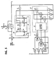
- the modified DFE receiver includes feedback filter 60' and includes only delay elements 22, 23, 28, 29 and correlators 31, 32.
- Modified selector circuit 70' includes only comparators 34, 35 and gates 25, 26.
- This embodiment further differs in that the output of decision circuit 15 is connected through a T-delay element 61 to the first tap of the feedback filter 60' and to the inputs of delay elements 22, 23. The first and second taps of feedback filter 60' are separated from each other, and the output of selector circuit 70' is connected to the second tap of the filter 60'.
- the output of delay element 61 is the decision symbol corresponding to such a T-delayed multipath component.
- the output of this delay element is coupled to multiplier 17 1 where it weighted by coefficient d 1 , producing a signal for canceling the T-delayed multipath component at the output of subtractor 14.
- a ⁇ 1 -delayed multipath component of a previous symbol is received and correlation is detected by correlator 31, resulting in the gate 25 being open to pass the ⁇ 1 -delayed decision symbol A - ⁇ 1 to the second tap of feedback filter 60' where it is multiplied by coefficient d 2 in the multiplier 17 2 , providing a signal for canceling the ⁇ 1 -delayed multipath component at the output of subtractor 14.
- Multipath components arriving at successive T-intervals following the ⁇ 1 -delayed multipath component are canceled as the ⁇ 1 -delayed decision symbol is shifted along the feedback filter 60'. Similar events occur with respect to a ⁇ 2 -delayed multipath component and those following it.
- correlator 32 produces an output which opens the gate 26 to pass the output of delay element 23 to the second tap of filter 60'.
- the output signal Z of the feedback filter 60' is given as follows: where L corresponds to ⁇ 1 or ⁇ 2 . It is seen that the first term of Equation (15) represents the output of feedback filter 60' for canceling the T-delayed multipath component associated with the transmitted symbol a 0 , the second term representing the filter output when canceling those components associated with the previously transmitted symbol a - ⁇ 1 or a - ⁇ 2 .
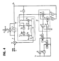
- Fig. 5 If there is a 2T-delayed multipath component of substantial magnitude in addition to the T-delayed component, an embodiment shown in Fig. 5 is suitable. This embodiment is similar to those of the Fig. 4 embodiment with the exception that it includes delay elements 62 and 63 of 2T-delay time, a correlator 64 and a gate 66. Correlator 64 provides detection of a correlation between the symbol x 1 and the output of delay 63 and gate 66 is connected between delay 62 and the second input of feedback filter 60'.
- selector 70" includes a maximum detector 65 for comparing the outputs of correlators 64, 31 and 32 with each other to find which one has the highest correlation value and supply a gate-on pulse to one of gates 66, 25 and 26 corresponding to the correlator that produces the highest correlation value.
- the multipath component of highest magnitude is selected in preference over other simultaneously arriving multipath components and the associated delayed decision symbol is selected in preference over other delayed decision symbols by selector circuit 70" and applied to the second tap of feedback filter 60', which cancels the highest magnitude multipath component at the output of subtractor 14.
Landscapes
- Engineering & Computer Science (AREA)
- Power Engineering (AREA)
- Computer Networks & Wireless Communication (AREA)
- Signal Processing (AREA)
- Noise Elimination (AREA)
- Cable Transmission Systems, Equalization Of Radio And Reduction Of Echo (AREA)
- Radio Transmission System (AREA)
Abstract
Description
- The present invention relates generally to receivers which can be used for digital radio communication systems or sonar detection systems, and more specifically to a decision feedback equalizer with an array of antennas, or sensors for canceling multipath components of a signal received via time-varying multipath-fading channels.
- The combined use of an array of spaced antennas, or sensors with a decision feedback equalizer for canceling multipath-fading related intersymbol interference is known, as shown and described in EP-A 604, 956, published on January 6, 1994. Using the well known least mean square (LMS) algorithm, the main lobe of the antennas is oriented in the arrival direction of a target signal, while forming a null in the direction of an undesired signal. However, if multipath components are arriving through very long return paths, their delay times are likely to exceed the length of the tapped-delay line of the equalizer, and hence no equalization would result at all. In particular, as the data transmission speed of a channel grows faster, the delay profile of the transmitted signal normalized by modulation speed extends, increasing the severity of the problem.
- A preferred embodiment of the present invention provides a decision feedback equalizer capable of canceling multipath-fading related intersymbol interference caused by very long multipath fading channels without increasing the length of the equalizer and canceling interference from jamming sources.
- A further embodiment of the present invention provides a solution to a collision problem that occurs when multipath components (echoes) of an earlier transmitted symbol arrive at the equalizer simultaneously with those of a later transmitted symbol.
- According to a first embodiment of the present invention, there is provided a decision feedback equalizer comprising sensor means for receiving transmitted signals and recovering baseband symbols from the received signals, forward filter means for weighting the recovered baseband symbols with first coefficients so that precursor multipath components of a transmitted symbol are canceled and combining the weighted baseband symbols to produce an output signal, a plurality of first delay means for providing delays to one of the baseband symbols of the sensor means to produce a short-delayed baseband symbol and a long-delayed baseband symbol, a plurality of correlator means for detecting correlations between the one of the baseband symbols and the short- and long-delayed baseband symbols, and a plurality of second delay means for providing delays to a decision symbol to produce a short-delayed decision symbol and a long-delayed decision symbol. Selector means is responsive to a correlation detected by one of the correlator means for selecting one of the short- and long-delayed decision symbols of the second delay means. Feedback filter means shifts the delayed decision symbol selected by the selector means along a tapped-delay line to produce successively shifted decision symbols, weighting the successively shifted decision symbols with second coefficients and combining the weighted decision symbols to produce an output signal that cancels postcursor multipath components of the transmitted symbol. The output signals of the forward and feedback filter means are combined to produce a pre-decision symbol. Decision means produces a decision output from the pre-decision symbol and applies the decision output to the plurality of second delay means as said decision symbol.
- According to a second embodiment of the present invention, there is provided a decision feedback equalizer comprising sensor means for receiving transmitted signals and recovering therefrom baseband symbols, forward filter means for weighting the recovered baseband symbols with first coefficients so that precursor multipath components of a transmitted symbol are canceled and combining the weighted baseband symbols to produce an output signal, first delay means for providing a long delay to one of the baseband symbols from the sensor means to produce a long-delayed baseband symbol, first correlator means for detecting a correlation between the one of the baseband symbols and the long-delayed baseband symbol, second delay means for providing a long delay to a decision symbol to produce a long-delayed decision symbol, and third delay means for providing a first short delay to a decision symbol to produce a first short-delayed decision symbol. Selector means is responsive to the correlation detected by the first correlator means for selecting the long-delayed decision symbol of the second delay means. Feedback filter means multiplies the first short-delayed decision symbol from the third delay means by a second coefficient to produce a first output signal that cancels a postcursor multipath component of the transmitted symbol, and successively shifts the long-delayed decision symbol selected by the selector means along a tapped delay line to produce successively shifted decision symbols, multiplies the successively shifted decision symbols by third coefficients, and combines the multiplied decision symbols to produce a second output signal that cancels postcursor multipath components of an earlier-transmitted symbol. The output signals of the forward and feedback filter means are combined to produce a pre-decision symbol, which is fed to decision means to produce a decision output which is applied to the second and third delay means as said decision symbol.
- The present invention will be described in further detail with reference to the accompanying drawings, in which:
- Fig. 1 is a block diagram of a decision feedback equalizer using an adaptive filter array according to an embodiment of the present invention;
- Fig. 2 is a diagram illustrating a simplified antenna array;
- Figs. 3A and 3B show antenna patterns obtained respectively by computer simulations of the equalizer of the present invention and a prior art equalizer having no feedback filter;
- Fig. 4 is a block diagram of a modified decision feedback equalizer of the present invention; and
- Fig. 5 is a block diagram of a further modification of the present invention.
- Referring now to Fig. 1, there is shown a DFE (decision feedback equalizer) receiver according to a first embodiment of the present invention. The receiver is most suitably used for applications such as digital radio communication systems or sonar detection systems where the quality of a transmitted signal is seriously affected by multipath components of the signal. At the transmit site, a symbol sequence {.....a-1, a0, a+1......} is quadrature-modulated onto a carrier in a format such as phase shift keying and transmitted. The receiver comprises an array of antennas 101 - 10N spaced at half-wavelength intervals of the transmitted carrier, a plurality of receivers 111 - 11N, and an
adaptive array filter 1 formed by a plurality of complex multipliers 121 - 12N and anadder 13. The outputs of antennas 101 - 10N are connected respectively to receivers 111 - 11N where they are quadrature-demodulated, recovering baseband vectors x1, x2, .... xN. These baseband vectors are applied to complex multipliers 121 - 12N, where they are respectively multiplied by weight coefficients c1, c2, ..., cN supplied from coefficient update circuits 401 - 40N, so that precursors (future symbols) of multipath-fading related intersymbol interference are canceled. The weighted vectors are summed together in combiner 13. - The output of the
adaptive array filter 1 is applied to asubtractor 14 where it is combined with a postcursor canceling signal supplied from afeedback filter 60 to produce an equalized output vector "y" at the output ofsubtractor 14. The output ofsubtractor 14 is coupled to adecision circuit 15 for making a decision in favor of logic-1 or logic-0 depending on the result of a comparison with a threshold value, producing a sequence of estimated symbols {ai}. - An
error detector 19 is connected across the input and output ofdecision circuit 15 to detect a decision error ε which is suitably weighted by a correction factor µ in amultiplier 20 and supplied to update circuits 401 - 40N. Each update circuit 40 includes acomplex correlator 41 in which the weighted decision error µ·ε is multiplied by the corresponding incoming symbol xi* (where (*) represents the complex conjugate, and i = 1, 2, ....., N). The weight coefficient ci is produced by coupling the output ofcorrelator 31 to the negative input of asubtractor 42 and applying its output through a symbol delay (T)element 43 to the other input ofsubtractor 42 forming a feedback loop so that it operates according to the LMS (least mean square) algorithm ci n = ci n-1 - µ xi* ε (where n is the time indicator) and hence the mean square value of the decision error ε is reduced to a minimum. Note that thedecision circuit 15,decision error detector 19,feedback filter 60 and tap-weight update circuits 501 - 50N form a decision feedback equalizer. - Postcursors (previous symbols) of multipath-fading related intersymbol interference are canceled by coupling the output of
decision circuit 15 to thefeedback filter 60 through aselector circuit 70. - The
feedback filter 60 comprises an M-stage tapped-delay line having symbol-delay elements 161 - 16M. When a transmitted symbol A0 is reproduced at the output ofdecision circuit 15, M past decision output symbols A-1, A-2, ....., A-M appear at the successive taps of the M-stage delay line and are presented to complex multipliers 171, 172, ....., 17M, respectively, where they are weighted by tap-weight coefficients d1, d2, ...., dM, respectively. The weighted tap signals are summed in anadder 18 to produce a postcursor canceling signal which is applied to thesubtractor 14 where it is subtracted from the output ofadder 13. - The tap-weight coefficient dj (where j = 1, 2, ...., M) is produced according to the LMS algorithm dj n = dj n-1 + µ A-j* ε. Specifically, the output of the
decision error detector 19 is coupled to tap-weight update circuits 501 - 50M. Each update circuit 50 includes acorrelator 51 for multiplying the weighted decision error µ·ε by complex conjugate of past decision output symbol A-i, the output ofcorrelator 51 being coupled to one input of an adder 52 whose output is connected through a symbol delay (T) element 53 to the other input of adder 52. - The DFE includes a plurality of
delay elements delay elements selector circuit 70.Delay elements decision circuit 15 to provide a delay time corresponding to T, τ1 and τ2, respectively, to decision symbol A0. Note that the delay time τ1 is greater than M x T, i.e., greater than the total delay time offeedback filter 60. The delay time τ2 is also greater than τ1. Delay times T, τ1 and τ2 are the delay times of multipath components of a transmitted symbol a0 and the T-delayed multipath component is a near-field reflection and the τ1- and τ2-delay times are far-field reflections propagating over long paths. The occurrences of these far-field components are known in advance from experiments. Typically, τ1 and τ2 are 100T and 200T, respectively. - A plurality of
delay elements receiver 111 to provide delays T, τ1 and τ2, respectively, to the received baseband symbol x1. - Correlations between the symbol x1 and the outputs of
delay elements correlators correlators -
Selector 70 includescomparators gates Comparators correlators gates feedback filter 60. - Assume that a transmitted symbol a0 has a multipath component arriving at an instant delayed by symbol interval T with respect to the symbol a0, a correlation is detected between them by
correlator 30 and a gate-on pulse is supplied fromcomparator 33 togate 24 to pass the output ofdelay element 21 to thefeedback filter 60. Therefore, a decision output symbol A0 corresponding to the transmitted symbol a0 appears at the output ofdelay element 21 as a past symbol A-1 time-coincident with the detection of the corresponding T-delayed multipath component bycorrelator 30. This past symbol is applied throughgate 24 to the first tap offeedback filter 60, where it is weighted by coefficient d1 for coupling to adder 18, a postcursor canceling output A-1 d1 at the output ofadder 18. Using this canceling signal, the T-delayed multipath component is canceled at the output ofsubtractor 14. - The decision symbol A-1 will then be shifted from delay element 161 to the next element 162 and appears at the second tap as a past decision symbol A-2 and weighted by coefficient d2. If there is a 2T-delayed multipath component associated with the transmitted symbol a0, the update circuit 50-2 will update the coefficient d2 using the weighted decision error µ·ε and so the past symbol A-2 is weighted with the updated coefficient d2, producing a canceling signal. This canceling signal is time coincident with the 2T-delayed multipath component which appears at the output of
combiner 13 at the instant two symbols delayed with respect to the symbol a0. A 3T-delayed multipath component, if present, will be canceled in a similar manner by a canceling signal A-3 d3. - Therefore, multipath components of a given transmitted symbol are canceled in this manner insofar as their longest delay does not exceed the total delay time of
feedback filter 60. - Quantitative analysis of the cancellation of multipath components whose longest delay does not exceed the total delay time of
feedback filter 60 will be given below using simultaneous linear equations. It will also be shown that theadaptive array filter 1 operates in the same manner as a feedforward filter which usually forms part of a decision feedback equalizer. - First, the output "y" of
subtractor 14 is given in the form:

- The weight coefficients ci and dj that minimize the mean square value of decision output e are determined by a normal equation (Wiener-Hoph Equation) using the orthogonality principle. From the following relations, the normal Equation can be derived, using linear weight coefficients as unknown variables.


- A simplified antenna array of the embodiment of Fig. 1 is illustrated in Fig. 2 to derive the normal equation using a simplified dispersive propagation model. Let hi represent the impulse response of a propagation path, with h0 representing a reference impulse response for the symbol of interest. The impulse responses h-i and h+i represent the precursor and the postcursor, respectively. The received signals are represented by convolution of the transmitted symbol sequence {ai} and the impulse response hi. The main signal component Si received by each antenna is given by h0 a0 and a multipath component received by each antenna is given by hi a0-i.
- Because of the 1/2 antenna spacing, the main signal component Si received by antenna 10i is delayed by an amount equal to exp {-j(i -1)φ0} with respect to the main component S1 received by the first antenna 101, where φ0 is the angle of arrival of the main signal Si to the axis of each antenna and is given by φ0 = π sin θ0. Therefore, the baseband vectors xi are represented as follows:


feedback filter 60 given by Equation (9), and S is a correlation vector correlating the symbol vector (x1, x2, .... xn) with the decision output symbol as given by Equation (10).

- Equation (6) indicates that the operation of the antenna array and the feedback filter is represented by simultaneous linear equations and that the antenna array functions as a feedforward filter of the decision feedback equalizer. Therefore, the present embodiment is not simply a sum of, but an integrated combination of, an antenna array and a decision feedback equalizer.
- A computer simulation was made for evaluating the present embodiment in terms of the directivity pattern of the antenna array which is given by:


- In the computer simulation, a four-element antenna array (each element with a 10 dB signal-to-noise ratio) and a single-delay tap feedback filter were used for a three-wave multipath fading model by representing a main signal as h0 a0, a phase-advanced multipath component as h-1 a+1, and a phase-lagged multipath component as h+1 a-1, and setting the amplitude of the impulse responses to a unit value (i.e., |h-1| = |h0| = |h+1| = 1, which represents the worst situation where the frequency selective fade is dominant) and setting the arrival angle of the main signal (θ0), phase-advanced and lagged multipath components (θ-1) and (θ+1) as θ0 = 20°, θ-1 = 45° and θ+1 = 20°, respectively. For purposes of comparison, a simulation was further made on a prior art four-element adaptive array receiver having no feedback filter, using the same operating parameters just described. Results of the computer simulations are shown in Figs. 3A and 3B.
- The antenna pattern shown at Fig. 3A is the result of the simulation derived from a four-element antenna array embodying the present invention. It is seen that the main lobe is oriented in the arrival direction (θ=20°) of the main signal and a null point (a point of zero gain) is formed in the arrival direction of the phase-advanced multipath component. While the phase-lagged multipath component h+1 a-1 is summed with the main signal, it is cancelled with an estimate of the symbol a-1 derived from the first delay-line tap of the feedback filter. It is therefore seen that, regardless of the presence of multipath components of a desired signal, the directivity pattern of the antenna array is constantly oriented in the arrival direction of the main component of the desired signal so that it is received at a maximum signal-to-noise ratio. On the other hand, the directivity pattern shown at Fig. 3B is the result of simulation derived from the prior art adaptive array receiver. Since the prior art receiver has no feedback filter and provides cancellation by forming null points in the antenna pattern, it is impossible to cancel the phase-lagged multipath component h+1 a-1 from the main component with which it is received with the same antenna gain. As a result, the reduction of the phase-lagged multipath component would cause the antenna gain to be reduced at the cost of the main signal.
- If the delay times of multipath components exceed the total delay time of the feedback filter, no equalization proceeds in the feedback filter until correlation is detected again. Under such conditions, the normal equation is given in the form:

- Multipath components whose delay times exceed the total delay time of the
feedback filter 60 may be few or nonexistent under normal multipath fading environment. However, very long delay paths may exist in a particular situation such as sonar and the like and multipath components coming through such long paths experience delays equal to or greater than τ1. Therefore, if there is a τ1-delayed multipath component for a given transmitted symbol a0, a correlation is detected between a0 and the τ1 component bycorrelator 31 and a gate-on pulse is supplied fromcomparator 34 togate 35 to pass the output of T-delay element 22 to thefeedback fiter 60. Therefore, a decision output symbol A0 corresponding to the transmitted symbol a0 appears at the output ofdelay element 22 simultaneously with the time of detection of the corresponding τ1-delayed multipath component. This past symbol is applied throughgate 25 to the first tap offeedback filter 60 as a past symbol A-τ1, where it is weighted by coefficient d1, producing a postcursor canceling signal A-τ1· d1 at the output ofadder 18. Using this signal,subtractor 14 cancels the τ1-delayed multipath component. If the τ1-delayed multipath component is followed by a series of multipath components at successive T (symbol) intervals, such multipath components will be adaptively canceled as the decision symbol A-τ1 is successively shifted along the tapped-delay line of the feedback filter. This process continues until the decision symbol A-τ1 appears as A-(τ1-M) at the end of the tapped-delay line of the feedback filter. This process can be represented by the following normal equation;
- Similar events occur when multipath components of a transmitted symbol return at instants delayed by amount equal to τ2 or greater.
- The multipath components of an earlier-transmitted symbol may arrive at the same instants as a significant multipath component of the most recent symbol. Under such circumstances, correlations will be simultaneously detected by
correlators gates - A solution to this problem is illustrated in Fig. 4 as a modification of the first embodiment of this invention. According to this embodiment, the modified DFE receiver includes feedback filter 60' and includes only delay
elements correlators gates decision circuit 15 is connected through a T-delay element 61 to the first tap of the feedback filter 60' and to the inputs ofdelay elements - Since it is known that a T-delayed multipath component is the dominant component, it is sufficient to take account only of this component in a situation where it is usually likely to collide with a multipath component that propagates over a very long path. The output of
delay element 61 is the decision symbol corresponding to such a T-delayed multipath component. The output of this delay element is coupled to multiplier 171 where it weighted by coefficient d1, producing a signal for canceling the T-delayed multipath component at the output ofsubtractor 14. Simultaneously with the arrival of the T-delayed multipath component, a τ1-delayed multipath component of a previous symbol is received and correlation is detected bycorrelator 31, resulting in thegate 25 being open to pass the τ1-delayed decision symbol A-τ1 to the second tap of feedback filter 60' where it is multiplied by coefficient d2 in the multiplier 172, providing a signal for canceling the τ1-delayed multipath component at the output ofsubtractor 14. Multipath components arriving at successive T-intervals following the τ1-delayed multipath component are canceled as the τ1-delayed decision symbol is shifted along the feedback filter 60'. Similar events occur with respect to a τ2-delayed multipath component and those following it. In this case,correlator 32 produces an output which opens thegate 26 to pass the output ofdelay element 23 to the second tap of filter 60'. - In this modified embodiment, the output signal Z of the feedback filter 60' is given as follows:

- If there is a 2T-delayed multipath component of substantial magnitude in addition to the T-delayed component, an embodiment shown in Fig. 5 is suitable. This embodiment is similar to those of the Fig. 4 embodiment with the exception that it includes
delay elements correlator 64 and agate 66.Correlator 64 provides detection of a correlation between the symbol x1 and the output ofdelay 63 andgate 66 is connected betweendelay 62 and the second input of feedback filter 60'. Since there is a likelihood of the 2T-delayed multipath component time-coincident with a multipath component associated with an earlier-transmitted symbol a-τ1 or a-τ2,selector 70" includes amaximum detector 65 for comparing the outputs ofcorrelators gates - In this way, the multipath component of highest magnitude is selected in preference over other simultaneously arriving multipath components and the associated delayed decision symbol is selected in preference over other delayed decision symbols by
selector circuit 70" and applied to the second tap of feedback filter 60', which cancels the highest magnitude multipath component at the output ofsubtractor 14.
Claims (7)
- A decision feedback equalizer comprising:sensor means (101-10N, 111-11N) for receiving transmitted signals and recovering baseband symbols from the received signals;forward filter means (1) for weighting the recovered baseband symbols with first coefficients so that precursor multipath components of a transmitted symbol are canceled and combining the weighted baseband symbols to produce an output signal;a plurality of first delay means (27-29) for providing delays to one of said baseband symbols of the sensor means (101-10N, 111-11N) to produce a short-delayed baseband symbol and a long-delayed baseband symbol;a plurality of correlator means (30-32) for detecting correlations between said one of the baseband symbols and said short- and long-delayed baseband symbols;a plurality of second delay means (21-23) for providing delays to a decision symbol to produce a short-delayed decision symbol and a long-delayed decision symbol;selector means (33-35, 24-26) responsive to a correlation detected by one of said correlator means for selecting one of the short- and long-delayed decision symbols of the second delay means (21-23);feedback filter means (60) for shifting the delayed decision symbol selected by the selector means along a tapped-delay line to produce successively shifted decision symbols, weighting the successively shifted decision symbols with second coefficients and combining the weighted decision symbols to produce an output signal that cancels postcursor multipath components of said transmitted symbol;means (14) for combining the output signals of said forward filter means (1) and said feedback filter means (60) to produce a pre-decision symbol; anddecision means (15) for producing a decision output from the pre-decision symbol and applying the decision output to said plurality of second delay means (21-23) as said decision symbol.
- A decision feedback equalizer as claimed in claim 1, wherein said sensor means comprises an array of spaced sensors (101-10N, 111-11N), further comprising:decision error detector means (19, 20) connected to said decision means (15) for detecting a decision error contained in the decision symbol;a plurality of first update circuits (401-40N) for producing a plurality of weight coefficients from the baseband symbols of said sensors (101-10N, 111-11N) and the decision error of said decision error detector (19, 20) and supplying said weight coefficients to said forward filter means (1) as said first coefficients; anda plurality of second update circuits (501-50M) for producing a plurality of tap-weight coefficients from said successively shifted decision symbols of said feedback filter means (60) and the decision error of said decision error detector (19, 20) and applying the tap-weight coefficients to said multipliers (17) of the feedback filter means as said second coefficients.
- A decision feedback equalizer comprising:sensor means (101-10N, 111-11N) for receiving transmitted signals and recovering therefrom baseband symbols;forward filter means (1) for weighting the recovered baseband symbols with first coefficients so that precursor multipath components of a transmitted symbol are canceled and combining the weighted baseband symbols to produce an output signal;first delay means (28-29) for providing a long delay to one of said baseband symbols from the sensor means (101-10N, 111-11N) to produce a long-delayed baseband symbol;first correlator means (31-32) for detecting a correlation between said one of the baseband symbols and the long-delayed baseband symbol;second delay means (22-23) for providing a long delay to a decision symbol to produce a long-delayed decision symbol;third delay means (61) for providing a first short delay to a decision symbol to produce a first short-delayed decision symbol;selector means (34-35, 64, 65, 25-26, 66) responsive to the correlation detected by said first correlator means for selecting the long-delayed decision symbol of said second delay means (22-23);feedback filter means (60) for weighting said first short-delayed decision symbol from said third delay means (61) with a second coefficient to produce a first output signal that cancels a postcursor multipath component of said transmitted symbol, and successively shifting said long-delayed decision symbol selected by the selector means along a tapped delay line to produce successively shifted decision symbols, weighting the successively shifted decision symbols with third coefficients, and combining the weighted decision symbols to produce a second output signal that cancels postcursor multipath components of a symbol transmitted earlier than said transmitted symbol;means (14) for combining the output signals of said forward filter means (1) and said feedback filter means (60) to produce a pre-decision symbol; anddecision means (15) for producing a decision output from the pre-decision symbol and applying the decision output to said second and third delay means (22-23, 61) as said decision symbol.
- A decision feedback equalizer as claimed in claim 3, further comprising:fourth delay means (63) for providing a second short delay to said one of the baseband symbols to produce a second short-delayed baseband symbol;second correlator means (64) for detecting a correlation between said one of the baseband symbols and said second short-delayed baseband symbol;fifth delay means (62) for providing a second short delay to said decision symbol from said decision means (15) to produce a second short-delayed decision symbol;wherein said selector means comprises:maximum detector means (65) for comparing output signals of said first and second correlator means (31-32, 64) and producing an output signal indicating which one of the output signals has a highest magnitude; anda plurality of gates (25-26, 66) responsive to the output signal of said maximum detector means (65) for applying one of the long-delayed decision symbol and the second short-delayed decision symbol to the second input terminal of said feedback filter means (60').
- A decision feedback equalizer as claimed in claim 3, wherein said sensor means comprises an array of spaced sensors (101-10N, 111-11N), further comprising:decision error detector means (19, 20) connected to said decision means (15) for detecting a decision error contained in the decision symbol;a plurality of first update circuits (401-40N) for producing a plurality of weight coefficients from the baseband symbols of said sensors (101-10N, 111-11N) and the decision error of said decision error detector (19, 20) and supplying said weight coefficients to said forward filter means (1) as said first coefficients; anda plurality of second update circuits (501-50M) for producing a plurality of tap-weight coefficients from said successively shifted decision symbols of said feedback filter means (60) and the decision error of said decision error detector (19, 20) and applying the tap-weight coefficients to said multipliers (17) of the feedback filter means as said second and third coefficients.
- A method for canceling multipath components of a transmitted symbol, comprising the steps of:a) receiving transmitted signals and recovering baseband symbols from the received signals;b) weighting said recovered baseband symbols by coefficients so that precursor multipath components of a transmitted symbol are canceled and combining the weighted baseband symbols to produce a first pre-decision symbol;c) providing delays to one of said baseband symbols to produce a short-delayed baseband symbol and a long-delayed baseband symbol and providing delays to a decision symbol to produce a short-delayed decision symbol and a long-delayed decision symbol;d) determining whether a correlation exists between said one of the baseband symbols and said short- and long-delayed baseband symbols and selecting one of the short- and long-delayed decision symbols depending on which one of said short- and long-delayed baseband symbols said correlation is detected;e) successively shifting the decision symbol selected by step (d) along a tapped-delay line to produce successively shifted decision symbols, weighting the successively shifted decision symbols with coefficients, and combining the weighted decision symbols to produce a canceling signal which cancels postcursor multipath components of said transmitted symbol;f) combining the canceling signal with said first pre-decision symbol of step (b) and producing a second pre-decision symbol; andg) making a decision on said second pre-decision symbol and producing a decision output and repeating step (c) by using the decision output as said decision symbol.
- A method for canceling multipath components of a transmitted symbol, comprising the steps of:a) receiving transmitted signals and recovering baseband symbols from the received signals;b) weighting said recovered baseband symbols with coefficients so that precursor multipath components of a transmitted symbol are canceled and combining the weighted baseband symbols to produce a first pre-decision symbol;c) providing a delay to one of said baseband symbols to produce a long-delayed baseband symbol and providing delays to a decision symbol to produce a short-delayed decision symbol and a long-delayed decision symbol;d) weighting the short-delayed decision symbol of step (c) with a coefficient to produce a first canceling signal that cancels a short-delayed postcursor multipath component of said transmitted symbol;e) determining whether a correlation exists between said one of the baseband symbols and said long-delayed baseband symbol and selecting the long-delayed decision symbol if said correlation is detected;f) successively shifting the long-delayed decision symbol selected by step (e) along a tapped-delay line to produce successively shifted decision symbols, weighting the successively shifted decision symbols with coefficients, and combining the weighted decision symbols to produce a second canceling signal that cancels long-delayed postcursor multipath components of a symbol transmitted earlier than said transmitted symbol;g) combining each of the first and second canceling signals with said first pre-decision symbol of step (b) and producing a second pre-decision symbol; andh) making a decision on said second pre-decision symbol and producing a decision output and repeating step (c) by using the decision output as said decision symbol.
Applications Claiming Priority (3)
| Application Number | Priority Date | Filing Date | Title |
|---|---|---|---|
| JP6322641A JP2697648B2 (en) | 1994-12-26 | 1994-12-26 | Decision feedback equalizer |
| JP32264194 | 1994-12-26 | ||
| JP322641/94 | 1994-12-26 |
Publications (3)
| Publication Number | Publication Date |
|---|---|
| EP0720334A2 true EP0720334A2 (en) | 1996-07-03 |
| EP0720334A3 EP0720334A3 (en) | 1998-08-05 |
| EP0720334B1 EP0720334B1 (en) | 2005-04-06 |
Family
ID=18145978
Family Applications (1)
| Application Number | Title | Priority Date | Filing Date |
|---|---|---|---|
| EP95309462A Expired - Lifetime EP0720334B1 (en) | 1994-12-26 | 1995-12-27 | Decision feedback equalizer for cancelling short- and long-multipath components using correspondingly delayed decision symbols |
Country Status (3)
| Country | Link |
|---|---|
| US (1) | US5646958A (en) |
| EP (1) | EP0720334B1 (en) |
| JP (1) | JP2697648B2 (en) |
Cited By (1)
| Publication number | Priority date | Publication date | Assignee | Title |
|---|---|---|---|---|
| US6912250B1 (en) | 1999-11-12 | 2005-06-28 | Cornell Research Foundation Inc. | System and methods for precursor cancellation of intersymbol interference in a receiver |
Families Citing this family (56)
| Publication number | Priority date | Publication date | Assignee | Title |
|---|---|---|---|---|
| FI98578C (en) * | 1995-04-24 | 1997-07-10 | Nokia Technology Gmbh | Method and circuit arrangement for compensating for delayed components of a communication signal |
| FR2737362B1 (en) * | 1995-07-25 | 1997-10-10 | Matra Communication | PROCESS FOR SELECTING THE PROPAGATION DELAYS RETAINED TO RECEIVE MESSAGES TRANSMITTED BY RADIOCOMMUNICATION WITH A SPREAD OF SPECTRUM |
| GB2309591B (en) * | 1996-01-27 | 1999-08-04 | Motorola Ltd | Apparatus and method for adaptive beamforming |
| JP3337613B2 (en) * | 1996-03-05 | 2002-10-21 | シャープ株式会社 | Spread spectrum communication system |
| JPH09284353A (en) * | 1996-04-18 | 1997-10-31 | Matsushita Commun Ind Co Ltd | Receiver |
| US6192087B1 (en) | 1996-11-15 | 2001-02-20 | Conexant Systems, Inc. | Method and apparatus for spectral shaping in signal-point limited transmission systems |
| US6278744B1 (en) | 1996-11-15 | 2001-08-21 | Conexant Systems, Inc. | System for controlling and shaping the spectrum and redundancy of signal-point limited transmission |
| US5870430A (en) * | 1996-12-26 | 1999-02-09 | Thomson-Csf | Process for multi-sensor equalisation in a radio receiver in the presence of interference and multiple propagation paths |
| US6680971B1 (en) * | 1998-05-18 | 2004-01-20 | Sarnoff Corporation | Passband equalizer for a vestigial sideband signal receiver |
| US6122224A (en) * | 1998-10-08 | 2000-09-19 | The United States Of America As Represented By The Secretary Of The Navy | Variable integration detection apparatus and method for multipath environments |
| US6553518B1 (en) | 1999-03-08 | 2003-04-22 | International Business Machines Corporation | Severe error detectors, methods and computer program products that use constellation specific error event thresholds to detect severe error events during demodulation of a signal comprising symbols from a plurality of symbol constellations |
| US6661847B1 (en) | 1999-05-20 | 2003-12-09 | International Business Machines Corporation | Systems methods and computer program products for generating and optimizing signal constellations |
| JP3554226B2 (en) * | 1999-06-18 | 2004-08-18 | 松下電器産業株式会社 | Receiver |
| JP3570671B2 (en) * | 1999-07-12 | 2004-09-29 | 富士通株式会社 | Wireless communication device |
| US6505222B1 (en) | 1999-10-29 | 2003-01-07 | International Business Machines Corporation | Systems methods and computer program products for controlling undesirable bias in an equalizer |
| US6967995B1 (en) | 1999-10-29 | 2005-11-22 | International Business Machines Corporation | Methods, systems and computer program products for carrier drop detection using a variable threshold |
| US6754258B1 (en) | 1999-10-29 | 2004-06-22 | International Business Machines Corporation | Systems, methods and computer program products for averaging learned levels in the presence of digital impairments based on patterns |
| US6792004B1 (en) | 1999-10-29 | 2004-09-14 | International Business Machines Corporation | Systems, methods and computer program products for averaging learned levels in the presence of robbed-bit signaling based on proximity |
| US6826157B1 (en) | 1999-10-29 | 2004-11-30 | International Business Machines Corporation | Systems, methods, and computer program products for controlling data rate reductions in a communication device by using a plurality of filters to detect short-term bursts of errors and long-term sustainable errors |
| US6792040B1 (en) | 1999-10-29 | 2004-09-14 | International Business Machines Corporation | Modems having a dual power mode capability and methods of operating same |
| US6823017B1 (en) | 1999-10-29 | 2004-11-23 | International Business Machines Corporation | Systems, methods and computer program products for filtering glitches from measured values in a sequence of code points |
| US6650657B1 (en) | 1999-10-29 | 2003-11-18 | International Business Machines Corporation | Systems, methods and computer program products for identifying digital impairments in modem signals |
| US6816545B1 (en) | 1999-10-29 | 2004-11-09 | International Business Machines Corporation | Systems, methods and computer program products for identifying digital impairments in modems based on clusters and/or skips in pulse code modulation signal levels |
| US6839382B1 (en) | 1999-10-29 | 2005-01-04 | International Business Machines Corporation | System, methods and computer program products for identifying digital impairments in modem signals using signature analysis and signal level comparison analysis |
| US6765955B1 (en) | 1999-10-29 | 2004-07-20 | International Business Machines Corporation | Methods, systems and computer program products establishing a communication configuration for a modem connection to compensate for echo noise |
| US6823004B1 (en) | 1999-10-29 | 2004-11-23 | International Business Machines Corporation | Methods, systems and computer program products for monitoring performance of a modem during a connection |
| US6611563B1 (en) | 1999-10-29 | 2003-08-26 | International Business Machines Corporation | Systems, methods and computer program products for data mode refinement of modem constellation points |
| US6662322B1 (en) | 1999-10-29 | 2003-12-09 | International Business Machines Corporation | Systems, methods, and computer program products for controlling the error rate in a communication device by adjusting the distance between signal constellation points |
| AU2001236855A1 (en) * | 2000-02-11 | 2001-08-20 | The Regents Of The University Of California | Method and apparatus for resolving multipath components for wireless location finding |
| US6862316B2 (en) * | 2000-03-27 | 2005-03-01 | Ntt Docomo, Inc. | Spatial and temporal equalizer and equalization method |
| IT1317249B1 (en) * | 2000-04-14 | 2003-05-27 | Cit Alcatel | METHOD AND APPARATUS FOR THE AUTOMATIC COMPENSATION OF THE DELAY FOR RADIO TRANSMISSIONS IN DIFFERENT SPACE. |
| JP2002287224A (en) | 2001-03-26 | 2002-10-03 | Minolta Co Ltd | Digital camera |
| FR2828032B1 (en) * | 2001-07-30 | 2003-09-12 | France Telecom | JOINT DETECTION OF CDMA CODES FOR MULTI-PATH DOWNLINK |
| US7020155B2 (en) * | 2001-09-28 | 2006-03-28 | Silicon Integrated Systems, Corp. | Collision detection method and apparatus for multiple access communication system |
| US6961373B2 (en) * | 2002-07-01 | 2005-11-01 | Solarflare Communications, Inc. | Method and apparatus for channel equalization |
| US7809021B2 (en) * | 2002-07-10 | 2010-10-05 | Solarflare Communications, Inc. | Communication system and encoding method having low overhead |
| US7065167B2 (en) * | 2002-07-10 | 2006-06-20 | Solarflare Communications, Inc. | Method and apparatus for constellation shaping |
| US7133425B2 (en) * | 2002-07-10 | 2006-11-07 | Solarflare Communications, Inc. | Communication system |
| US7116734B1 (en) | 2002-07-15 | 2006-10-03 | National Semiconductor Corporation | Method and system for providing maximum likelihood detection with decision feedback interference cancellation |
| US6920333B2 (en) * | 2002-09-12 | 2005-07-19 | George L. Yang | Decision feedback equalizer with embedded coherent signal combiner |
| JP4309110B2 (en) * | 2002-09-27 | 2009-08-05 | パナソニック株式会社 | Adaptive antenna wireless communication device |
| US6912208B2 (en) * | 2002-11-07 | 2005-06-28 | Solarflare Communications, Inc. | Method and apparatus for equalization and crosstalk mitigation |
| US7164764B2 (en) * | 2002-11-07 | 2007-01-16 | Solarflare Communications, Inc. | Method and apparatus for precode crosstalk mitigation |
| US7120193B2 (en) * | 2002-11-08 | 2006-10-10 | Scintera Networks, Inc. | Decision feedback equalizer with dynamic feedback control |
| US7292631B2 (en) * | 2003-03-26 | 2007-11-06 | Infineon Technologies Ag | Feed forward equalizer and a method for analog equalization of a data signal |
| US8363535B2 (en) * | 2003-04-28 | 2013-01-29 | Marvell International Ltd. | Frequency domain echo and next cancellation |
| US7002897B2 (en) * | 2003-04-28 | 2006-02-21 | Solarflare Communications, Inc. | Multiple channel interference cancellation |
| JP2006524970A (en) * | 2003-04-28 | 2006-11-02 | ソーラーフレア・コミュニケーションズ・インコーポレイテッド | Eliminate interference in multiple channels |
| US20040213354A1 (en) * | 2003-04-28 | 2004-10-28 | Jones William W. | Mixed domain cancellation |
| US7483479B2 (en) * | 2004-09-16 | 2009-01-27 | Keyeye Communications | Scaled signal processing elements for reduced filter tap noise |
| US7542508B2 (en) * | 2005-04-21 | 2009-06-02 | Lsi Logic Corporation | Continuous-time decision feedback equalizer |
| US8761387B2 (en) | 2006-05-04 | 2014-06-24 | Mindspeed Technologies, Inc. | Analog transmit crosstalk canceller |
| US7720068B2 (en) | 2006-08-23 | 2010-05-18 | Solarflare Communications, Inc. | Method and system for a multi-rate gigabit media independent interface |
| US7808407B2 (en) | 2007-06-15 | 2010-10-05 | Solarflare Communications, Inc. | Sub-channel distortion mitigation in parallel digital systems |
| US7948862B2 (en) | 2007-09-26 | 2011-05-24 | Solarflare Communications, Inc. | Crosstalk cancellation using sliding filters |
| CN101897152B (en) | 2007-11-12 | 2014-01-15 | 马维尔国际有限公司 | Active idle communication system |
Citations (5)
| Publication number | Priority date | Publication date | Assignee | Title |
|---|---|---|---|---|
| US4912557A (en) * | 1988-05-16 | 1990-03-27 | Faroudja Y C | Control method for television ghost reduction system |
| EP0387498A2 (en) * | 1989-02-24 | 1990-09-19 | KE KOMMUNIKATIONS-ELEKTRONIK GMBH & CO | Digital transmission system for transmitting a plurality of binary signals on a conductor pair |
| GB2238932A (en) * | 1989-11-17 | 1991-06-12 | Nec Corp | Decision feedback equalizer including forward part whose signal reference point is shiftable depending on channel response |
| EP0565104A2 (en) * | 1992-04-09 | 1993-10-13 | Nec Corporation | Interference canceller with feedforward transversal filter having switched tap-gain coefficients |
| EP0604956A2 (en) * | 1992-12-28 | 1994-07-06 | Nec Corporation | Decision feedback equalizer with adaptive filter array operating as feedforward filter of the equalizer |
Family Cites Families (5)
| Publication number | Priority date | Publication date | Assignee | Title |
|---|---|---|---|---|
| US4789994A (en) * | 1987-08-12 | 1988-12-06 | American Telephone And Telegraph Company, At&T Bell Laboratories | Adaptive equalizer using precursor error signal for convergence control |
| JP2551210B2 (en) * | 1990-07-17 | 1996-11-06 | 日本電気株式会社 | Adaptive equalizer |
| JP2720721B2 (en) * | 1992-08-21 | 1998-03-04 | 日本電気株式会社 | Modem |
| US5440583A (en) * | 1992-08-24 | 1995-08-08 | Nec Corporation | Decision feedback equalizer with second-order recursive filter controlled with two feedback coefficients |
| JP2541503B2 (en) * | 1994-04-28 | 1996-10-09 | 日本電気株式会社 | Interference wave remover |
-
1994
- 1994-12-26 JP JP6322641A patent/JP2697648B2/en not_active Expired - Lifetime
-
1995
- 1995-12-26 US US08/577,009 patent/US5646958A/en not_active Expired - Lifetime
- 1995-12-27 EP EP95309462A patent/EP0720334B1/en not_active Expired - Lifetime
Patent Citations (5)
| Publication number | Priority date | Publication date | Assignee | Title |
|---|---|---|---|---|
| US4912557A (en) * | 1988-05-16 | 1990-03-27 | Faroudja Y C | Control method for television ghost reduction system |
| EP0387498A2 (en) * | 1989-02-24 | 1990-09-19 | KE KOMMUNIKATIONS-ELEKTRONIK GMBH & CO | Digital transmission system for transmitting a plurality of binary signals on a conductor pair |
| GB2238932A (en) * | 1989-11-17 | 1991-06-12 | Nec Corp | Decision feedback equalizer including forward part whose signal reference point is shiftable depending on channel response |
| EP0565104A2 (en) * | 1992-04-09 | 1993-10-13 | Nec Corporation | Interference canceller with feedforward transversal filter having switched tap-gain coefficients |
| EP0604956A2 (en) * | 1992-12-28 | 1994-07-06 | Nec Corporation | Decision feedback equalizer with adaptive filter array operating as feedforward filter of the equalizer |
Cited By (1)
| Publication number | Priority date | Publication date | Assignee | Title |
|---|---|---|---|---|
| US6912250B1 (en) | 1999-11-12 | 2005-06-28 | Cornell Research Foundation Inc. | System and methods for precursor cancellation of intersymbol interference in a receiver |
Also Published As
| Publication number | Publication date |
|---|---|
| US5646958A (en) | 1997-07-08 |
| EP0720334A3 (en) | 1998-08-05 |
| JPH08181641A (en) | 1996-07-12 |
| JP2697648B2 (en) | 1998-01-14 |
| EP0720334B1 (en) | 2005-04-06 |
Similar Documents
| Publication | Publication Date | Title |
|---|---|---|
| US5646958A (en) | Decision feedback equalizer for canceling short-and long-multipath components using correspondingly delayed decision symbols | |
| US5689528A (en) | Decision feedback equalizer with adaptive filter array operating as feedforward filter of the equalizer | |
| US4328585A (en) | Fast adapting fading channel equalizer | |
| US6205166B1 (en) | CDMA receiver with antenna array adaptively controlled with combined errors of despread multipath components | |
| EP0687076B1 (en) | Diversity communication system with arrays of antennas using adaptive mezched filters and decision feedback equalizers | |
| EP0631399B1 (en) | Method and apparatus for interference cancellation and adaptive equalisation in diversity reception | |
| US5493307A (en) | Maximal deversity combining interference cancellation using sub-array processors and respective delay elements | |
| US5822380A (en) | Apparatus and method for joint channel estimation | |
| EP0894367B1 (en) | Method and apparatus for interference rejection with different beams, polarizations, and phase references | |
| US20060029149A1 (en) | Method and apparatus for receiving signals in MIMO system | |
| US6243415B1 (en) | Process of multisensor equalization allowing multisensor reception in the presence of interference and multiple propagation paths and receiver for the implementation thereof | |
| US5692018A (en) | Time-diversity interference canceler with add/subtract/select circuit responsive to decision error | |
| EP0602615B1 (en) | Sidelobe cancellation and diversity reception using a single array of auxiliary antennas | |
| US20020044615A1 (en) | Signal extraction method and apparatus in wireless communication system | |
| US5796788A (en) | Method and apparatus for interference decorrelation in time and space | |
| Mayrargue | A blind spatio-temporal equalizer for a radio-mobile channel using the constant modulus algorithm (CMA) | |
| EP0757456B1 (en) | Diversity receivers | |
| US5379046A (en) | Interference wave canceller | |
| US7508863B2 (en) | Method of processing multi-path signals | |
| US5870430A (en) | Process for multi-sensor equalisation in a radio receiver in the presence of interference and multiple propagation paths | |
| US6763077B1 (en) | Receiving apparatus and array combining method | |
| JP3537203B2 (en) | Antenna diversity receiver | |
| JPH07226704A (en) | Adaptive equalizer | |
| GB2365715A (en) | A circuit for a communications receiver | |
| CA2240483A1 (en) | Multisensor equalisation method and device enabling multisensor reception in the presence of interference and multipath propagation |
Legal Events
| Date | Code | Title | Description |
|---|---|---|---|
| PUAI | Public reference made under article 153(3) epc to a published international application that has entered the european phase |
Free format text: ORIGINAL CODE: 0009012 |
|
| AK | Designated contracting states |
Kind code of ref document: A2 Designated state(s): FR GB IT |
|
| K1C3 | Correction of patent application (complete document) published |
Effective date: 19960703 |
|
| PUAL | Search report despatched |
Free format text: ORIGINAL CODE: 0009013 |
|
| AK | Designated contracting states |
Kind code of ref document: A3 Designated state(s): FR GB IT |
|
| 17P | Request for examination filed |
Effective date: 19980907 |
|
| 17Q | First examination report despatched |
Effective date: 20031230 |
|
| GRAP | Despatch of communication of intention to grant a patent |
Free format text: ORIGINAL CODE: EPIDOSNIGR1 |
|
| GRAS | Grant fee paid |
Free format text: ORIGINAL CODE: EPIDOSNIGR3 |
|
| GRAA | (expected) grant |
Free format text: ORIGINAL CODE: 0009210 |
|
| AK | Designated contracting states |
Kind code of ref document: B1 Designated state(s): FR GB IT |
|
| REG | Reference to a national code |
Ref country code: GB Ref legal event code: FG4D |
|
| PLBE | No opposition filed within time limit |
Free format text: ORIGINAL CODE: 0009261 |
|
| STAA | Information on the status of an ep patent application or granted ep patent |
Free format text: STATUS: NO OPPOSITION FILED WITHIN TIME LIMIT |
|
| 26N | No opposition filed |
Effective date: 20060110 |
|
| ET | Fr: translation filed | ||
| PGFP | Annual fee paid to national office [announced via postgrant information from national office to epo] |
Ref country code: GB Payment date: 20141224 Year of fee payment: 20 |
|
| PGFP | Annual fee paid to national office [announced via postgrant information from national office to epo] |
Ref country code: FR Payment date: 20141208 Year of fee payment: 20 |
|
| PGFP | Annual fee paid to national office [announced via postgrant information from national office to epo] |
Ref country code: IT Payment date: 20141126 Year of fee payment: 20 |
|
| REG | Reference to a national code |
Ref country code: GB Ref legal event code: PE20 Expiry date: 20151226 |
|
| PG25 | Lapsed in a contracting state [announced via postgrant information from national office to epo] |
Ref country code: GB Free format text: LAPSE BECAUSE OF EXPIRATION OF PROTECTION Effective date: 20151226 |