EP0720331A1 - Arrangement for chaining intermediate modules, in particular repeaters and installation equipped therewith - Google Patents
Arrangement for chaining intermediate modules, in particular repeaters and installation equipped therewith Download PDFInfo
- Publication number
- EP0720331A1 EP0720331A1 EP95402933A EP95402933A EP0720331A1 EP 0720331 A1 EP0720331 A1 EP 0720331A1 EP 95402933 A EP95402933 A EP 95402933A EP 95402933 A EP95402933 A EP 95402933A EP 0720331 A1 EP0720331 A1 EP 0720331A1
- Authority
- EP
- European Patent Office
- Prior art keywords
- modules
- access control
- module
- control signal
- output
- Prior art date
- Legal status (The legal status is an assumption and is not a legal conclusion. Google has not performed a legal analysis and makes no representation as to the accuracy of the status listed.)
- Ceased
Links
Images
Classifications
-
- H—ELECTRICITY
- H04—ELECTRIC COMMUNICATION TECHNIQUE
- H04L—TRANSMISSION OF DIGITAL INFORMATION, e.g. TELEGRAPHIC COMMUNICATION
- H04L12/00—Data switching networks
- H04L12/28—Data switching networks characterised by path configuration, e.g. LAN [Local Area Networks] or WAN [Wide Area Networks]
- H04L12/44—Star or tree networks
Definitions
- the invention relates to chaining arrangements between intermediate modules, in particular of the repeater type, for a communication installation comprising transceiver terminals communicating via a common packet transmission link to which they are connected by the modules. It also relates to communication installations equipped with such arrangements.
- transceiver terminals which communicate with each other via a common packet transmission link which they operate in timeshare, each transmitting according to its needs, when the link is available.
- These installations conventionally include modules, intermediaries, responsible for establishing communication operations for one or more transceiver terminals to which they are then assigned.
- these modules often have a concentration function and are therefore shared by several transceiver terminals.
- these modules often often provide uniformity of the signals transmitted between a terminal in transmission and a terminal in reception by regenerating these signals so that they are always between determined admission limits.
- modules called repeaters which are made to fulfill such functions in the case of common packet transmission links as envisaged above, in particular in the case of the links intended to make local networks, such as for example a standardized ETHERNET network.
- each module has an input intended to receive a blocking access control signal, of binary type, indicating whether the common link is accessible to it or not and if consequently it can come to transmit data therefrom. of a transceiver terminal with which it is associated.
- Each module also has an output for transmitting the access control signal, when it is itself wishing to access the common link in order to transmit there.
- This solution makes it possible to easily create the auxiliary network of control links, since a single control link is sufficient to connect the access control signal input of a module to the access control signal output of the module located upstream of it in the chain, if there is such a module, and since the module located upstream of the chain can permanently receive the control signal access, binary, indicating to him that the link is accessible to him, in the absence of transmission in progress.
- the chain auxiliary network solution mentioned above is only suitable when the number of chained modules is limited, because it introduces delays in transmission of the access control signals which quickly become unacceptable. It is recalled by way of example that the IEEE 802.3 standard provides that the delay in transmitting a packet must be less than eight bit times, ie 800 nanoseconds, in the most unfavorable case, between two ports, one of input and the other output, for terminals linked together by a packet transmission link, via repeater type modules, as envisaged above. In addition, the operation of the assembly served by the chained modules is likely to be seriously disturbed in the event of an interruption of the chain, for example in the event of a fault or break in a link or else in the event of a failure or possibly removing a module.
- a backplane card carrying appropriate point-to-point links then makes it possible to interconnect cards corresponding to units communicating with one another in the same mode and in particular modules, as mentioned above, for the management of these modules.
- the invention therefore proposes an arrangement of chaining between intermediate modules, for communication installation provided with transceiver terminals communicating by a digital packet transmission link, common, through intermediate modules, in particular of the type repeater, each comprising an input and an output for access control signal in transmission to the common link allowing a module to block another to the input of which it is connected by its output, via one of the control links an auxiliary sub-network connecting the access control signal inputs and outputs of the "n" modules of the installation.
- the modules each have their access control signal input connected to the output of a first concentrator logic circuit, this circuit comprising "p" inputs capable of being each connected to a signal output. of access control of different modules, "p” being an integer greater than two, and in that the modules each have their access control signal output connected to a diffusion circuit making it possible to simultaneously attack the inputs of access control signal from "p" different modules.
- a second concentrator logic circuit is inserted between the access control signal output of each module and the diffusion circuit specific to this module, this second concentrator logic circuit being connected by a first input at the access control signal output of the module considered and by a second input at the output of the first concentrator logic circuit of the module.
- each module a diffusion circuit constituted by a first switch which is governed by a control unit of the installation and which is connected by point-to-point links to the inputs of access control signal from all the other modules and a second switch which is also governed by said control unit and which connects the inputs of the first concentrator logic circuit associated with the module in question to as many individual access control signal outputs modules, this second switch being connected by point-to-point control links to the access control outputs of all the other modules.
- each module is associated on a carrier card with the two concentrator logic circuits and with the two switches which serve it, this card coming to connect to a backplane card which is in particular provided for receiving other carrier cards communicating according to the same packet mode and which in particular comprises the control links intended to make it possible to interconnect the inputs and outputs of the access control signal of the modules carried by these cards.
- each of the modules is simultaneously connected to a number "p" of control links, by the "p" of access control signal inputs of the first concentrator logic circuit serving it, this number "p” being such that each transceiver terminal is connected to any other transceiver terminal of the installation by at least one path for which the delay of transmission of an access control signal, through the
- the sequence formed by the modules to which the terminals considered are attached, the control links, the concentrator logic circuits and the borrowed switches, is less than the maximum delay allowed for the transmission of a packet between terminals.
- the invention finally proposes a communication installation comprising transceiver terminals communicating via a common packet transmission link to which they are connected by the intermediate modules, in particular of repeater type, each comprising an input and a output for access control signal in transmission to the common link allowing a module to block another to the input of which it is connected by its output, via one of the control links, point-to-point type of an auxiliary sub-network connecting the inputs and outputs of the access control signal of the modules of the installation.
- This installation comprises a chaining arrangement between modules having at least one of the characteristics set out above.
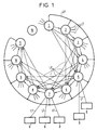
- FIG. 1 presents a block diagram of a communication installation comprising a chaining arrangement, according to the invention, between terminal service modules communicating with each other by a common packet transmission link.
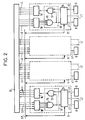
- FIG. 2 shows a partial diagram of an exemplary arrangement according to the invention.
- the chaining arrangement according to the invention is more particularly intended for a communications installation which is capable of comprising a plurality of constituent, specialized and modular units which are brought to communicate with one another according to their respective specializations and according to the services of communication implemented, these units being in particular connected by an interconnection network made up of point-to-point type links which are physically structured and temporally governed according to the characteristics of the two units which each of these links specifically connects.
- This installation therefore comprises at least transceiver terminals 0 which are intended to communicate with one another via a common digital link for transmitting LP packets to which these terminals 0 are connected by modules, called intermediates, individually contained in units referenced from 1 to 11 in FIG. 1.
- the "n" units here referenced 1 to 11 do not usually constitute only part of the installation units mentioned above, they are interconnected by a point-to-point LC sub-network of links where the links are physically structured and temporally governed in an identical manner, this sub-network, here called auxiliary, being one of the essential elements of the chaining arrangement according to the invention.
- the installation is likely to include other units, here symbolized by a unit referenced 12, and other subnets here not shown for reasons of simplification.
- the unit 12 is for example a main control unit organized around at least one processor and a memory assembly.
- the modules contained in units 1 to 11 are of the repeater type and correspond, for example, to DP 83950 circuits, called RICs, from the company NATIONAL SEMICONDUCTOR. They are supervised by control arrangements 19 in the units which comprise them. Each control arrangement 19 which is not fully detailed in Figure 2 where it is shown, being organized around a microprocessor with which is associated a set of memories, not shown, this microprocessor communicating by an appropriate interface with the repeater that 'he supervises.
- each of the units 1 to 11 is assumed to have an input and an output for an access control signal in transmission to the common packet link LP, the access control signals, here assumed to be of the type binary logic, being intended to be conveyed between the modules by the LC links, here called control, of the auxiliary sub-network interconnecting the module units 1 to 11.
- each module is intended to serve one or more terminals 0 which are directly attached to it by links here referenced LT to offer each of them communicate with all the other terminals 0 of the installation via the common packet transmission link LP. These other terminals 0 are themselves connected to this common link via modules and via LT links.
- terminals 0 are likely to be very diverse, ranging from a simple subscriber terminal directly or indirectly accessible in packet mode to the server terminal which can be used by a large number of users.
- the auxiliary sub-network constituted by the LC control links is produced at the level of a card 13, called the backplane, on which cards corresponding in particular to the units module 0 to 11 are connected at card positions determined by means of suitable connectors, known and not shown here.
- the connectors mounted on the backplane board make it possible to connect point-to-point and between them the boards they receive respectively, in particular via the LC control links of the auxiliary sub-network mentioned above. - above for module units 1 to 11.
- connection of each module to the common packet transmission link LP or more precisely of each card 1 to 11 carrying such a module is provided at the level of other module card connectors, not shown and here assumed to be specifically provided for such a common LP connection.
- This includes, for example, a bus type link with data coding in NRZ form, often referred to as "INTERRIC” in the case of so-called “RIC” repeater modules, it of course includes other shared links for example for handling collisions.
- each module connected to the common link LP has an input and an output signal for the access control signal in transmission to this link, it being understood that the latter can only receive a transmission from a single terminal 0 and therefore via only one module at a time and all the modules on the other hand receive identically any transmission transmitted via the common LP link.
- each module identically referenced 14 at the level of units 1 and 11, which is for example of the repeater type already mentioned above, is connected by its signal input of access control, here referenced "acki", at the output of a first concentrator logic circuit 15.
- access control here referenced "acki”
- the latter is here supposed to be carried out using an AND type door and it is provided with a number "p" of inputs assumed to be equal to four in this figure 2. Its function is to transmit to its output the access control signal emitted by its "acko" output from a module having to transmit, when the latter is connected to the one of the "p" inputs of this first logic circuit 15 by one or more control links LC in succession, this signal being here assumed to be of low binary level.
- Each of the "p" inputs of each first logic circuit 15 associated with a module 14 in a module unit is provided connected to one end of an LC link different from the auxiliary sub-network carried by the backplane card.
- each module 14, as mentioned above in connection with FIG. 2, is connected by its access control signal output here referenced “acko" to a diffusion circuit 16 of the unit containing the module 14 considered.
- Each diffusion circuit 16 is for example constituted by a switch of the usual type making it possible to connect the "acko" output of the module 14 to which it is connected to "p" LC control links of the auxiliary sub-network so as to be able to act on the access control signal input of "p" different modules simultaneously.
- a second logic concentrator circuit 17 is inserted between the access control signal output "acko" of each module 14 and the diffusion circuit 16 which serves it directly.
- This second logic circuit 17 is here supposed to be produced using a NAND type gate connected by a first input to the "acko" output of the module 14 considered and by a second input at the output of the first logic circuit 15 which attacks the 'acki' access control input of this same module, so as to allow the diffusion of the access control signal which it receives from a module having to be transmitted which is either the module to which it is connected by its second input is a module to which it is connected via its first input.
- first input of a second concentrator logic circuit is connected to the output of the first concentrator logic circuit associated with the same module allows a transmission of the access control signal, here assumed to be low, which short-circuits the module associated with the two logic circuits considered and which therefore makes it possible to avoid adding the transmission delay which this module would introduce to the time of transfer of the access control signal to the various modules of the chaining arrangement, this being developed more low.
- a switch 18 is inserted between the inputs of the first logic circuit 15 associated with a module 14 on a module unit card and the control links LC carried by the backplane card 13 which connect in point-to-point module unit cards, here 1 to 11, via the connectors, not shown, used for their respective connections.
- the unit 1, located at the head of the chain does not have to receive an access control signal from a unit located upstream.
- the level of the binary signals permanently applied to the inputs of the first logic circuit, not shown in FIG. 1, of this chain head unit is fixed to maintain the output of this circuit at a level which prevents it from blocking as long the module at the "acki" control signal input to which it is directly connected than those of the modules to which it can access via the second logic circuit of its unit to an input to which it is also directly connected.
- the first logic circuit of unit 2 located immediately downstream of unit 1 in the chain presented in FIG. 1, can only receive an access control signal by that of its inputs which is connected to this single unit 1 located upstream and it must therefore have its other inputs brought to a binary level which makes them ineffective, like those of the first logic circuit of unit 1.
- the first logic circuit not shown from unit 3 and that from unit 4, can respectively receive an access control signal only by those of their respective inputs which are connected to a unit located at upstream and therefore have their other inputs rendered ineffective as indicated above.
- switch 18 and the switch constituting the diffusion circuit 16 for the same module are here assumed on the card of the unit comprising this module. It is for example provided that all the switches associated with the modules on the unit cards are controlled by the microcontrollers of the control arrangements 19 of the units which comprise them, according to the orders established centrally for example by the main control unit 12 mentioned above.
- the backplane card 13 connects all the point-to-point module unit cards to each other via the auxiliary control link LC. It is therefore possible to establish and modify on request, via the main control unit 12 and the microcontrollers of the control arrangements 19, the connections between the "p" inputs of a concentrator logic circuit 15 and "p" of the LC control links which are established between the module card carrying this circuit and the other module cards, it being understood that the transmission of the access control signal from a module 14 having to transmit to the other modules 14 does not imply that all possible LC control links between module cards are used.
- the establishment of the connections between the concentrator logic circuit 17 and "p" of the LC control links established between the card carrying this circuit and the other module cards is of course achievable in an analogous manner via the control unit. main 12.
- each module is assumed to be directly connected by its access control signal output to four access control signal inputs relating to as many different modules, via its broadcasting circuit and a link Point-to-point LC per entry reached.
- the transmission time of an access control signal between two modules considered one as a transmitter and the other as a receiver depends on the transmission times of this signal through the various constituent elements that crosses this signal from this transmitter module to this receiver module.
- the module supposed to be a repeater of one of the units presented, for example the unit 11, is thus capable of directly receiving an access control signal from each unit module, connected to its access control signal input, as symbolized by the arrow LC links oriented towards this unit 11 from units 7, 8, 9 and 10.
- This same unit module 11 can also receive the access control signal from one of the units connected to the access control input of one of units 7, 8, 9 and 10, such as units 3, 4, 5, 6, 8, it being understood that at this stage alternative paths exist for transmitting an access control signal to the unit 11 via two LC control links in series, for example from unit 3 via units 7 and 9 or from from unit 6 via units 7 and 10.
- the control of the switches 16 and 18 of the module units via the control unit 12 makes it possible to carry out a partial or complete reconfiguration of the chaining arrangement, if necessary.
- the configuration is such that two separate paths allow any unit to be connected to any other unit located downstream in the chain, with the exception of the one which is the first downstream of it, these paths always passing through different intermediate units, when such intermediate units are involved.
- the two paths connecting unit 1 to unit 11 pass respectively through units 5 and 9 for one and through units 3 and 7 for the other.
- modules which includes an auxiliary sub-network of LC control links where each module is connected to any other module by at least two paths of transmission of the access control signal so as to eliminate the risks of simultaneous transmissions of data packets by different modules on the LP packet transmission link shared by the modules.
Landscapes
- Engineering & Computer Science (AREA)
- Computer Networks & Wireless Communication (AREA)
- Signal Processing (AREA)
- Small-Scale Networks (AREA)
Abstract
Description
L'invention concerne les agencements de chaînage entre modules intermédiaires, notamment de type répéteur, pour installation de communication comportant des terminaux émetteurs-récepteurs communiquant par l'intermédiaire d'une liaison de transmission de paquets commune à laquelle ils sont reliés par les modules. Elle concerne aussi les installations de communication équipées de tels agencements.The invention relates to chaining arrangements between intermediate modules, in particular of the repeater type, for a communication installation comprising transceiver terminals communicating via a common packet transmission link to which they are connected by the modules. It also relates to communication installations equipped with such arrangements.
Il existe de nombreuses installations de communication comportant des terminaux émetteurs-récepteurs qui communiquent entre eux par l'intermédiaire d'une liaison de transmission de paquets commune qu'ils exploitent en temps partagé, chacun émettant en fonction de ses besoins, lorsque la liaison est disponible. Ces installations comportent classiquement des modules, intermédiaires, chargés des opérations de mise en communication pour un ou plusieurs terminaux émetteurs-récepteurs auxquels ils sont alors affectés.There are numerous communication installations comprising transceiver terminals which communicate with each other via a common packet transmission link which they operate in timeshare, each transmitting according to its needs, when the link is available. These installations conventionally include modules, intermediaries, responsible for establishing communication operations for one or more transceiver terminals to which they are then assigned.
Pour diverses raisons et notamment des raisons de coût, ces modules ont souvent une fonction de concentration et sont donc partagés par plusieurs terminaux émetteurs-récepteurs.For various reasons and in particular cost reasons, these modules often have a concentration function and are therefore shared by several transceiver terminals.
De plus ces modules assurent souvent en supplément une uniformisation des signaux transmis entre un terminal en émission et un terminal en réception en régénérant ces signaux pour qu'ils soient toujours compris entre des limites d'admission déterminées.In addition, these modules often often provide uniformity of the signals transmitted between a terminal in transmission and a terminal in reception by regenerating these signals so that they are always between determined admission limits.
Il existe des modules appelés répéteurs qui sont réalisés pour remplir de telles fonctions dans le cas de liaisons de transmission de paquets communes telles qu'envisagées ci-dessus, en particulier dans le cas des liaisons prévues pour réaliser des réseaux locaux, tel que par exemple un réseau normalisé de type ETHERNET.There are modules called repeaters which are made to fulfill such functions in the case of common packet transmission links as envisaged above, in particular in the case of the links intended to make local networks, such as for example a standardized ETHERNET network.
Pour profiter au maximum des possibilités de transmission offertes par une liaison commune partagée de cette manière dans le cadre d'une même installation, il est connu de régir l'ensemble que forment les modules et la liaison commune à laquelle ils sont connectés au travers d'un réseau auxiliaire de liaisons de commande reliées aux modules.To make the most of the transmission possibilities offered by a common link shared in this way within the framework of the same installation, it is known to govern the assembly formed by the modules and the common link to which they are connected through '' an auxiliary network of control links connected to the modules.
Dans une forme connue de réalisation, chaque module comporte une entrée prévue pour recevoir un signal bloquant de contrôle d'accès, de type binaire, indiquant si la liaison commune lui est accessible ou non et si en conséquence il peut venir y émettre des données provenant d'un terminal émetteur-récepteur auquel il est associé. Chaque module comporte aussi une sortie pour émettre le signal de contrôle d'accès, lorsqu'il est lui-même désireux d'accéder à la liaison commune en vue d'y émettre.In a known embodiment, each module has an input intended to receive a blocking access control signal, of binary type, indicating whether the common link is accessible to it or not and if consequently it can come to transmit data therefrom. of a transceiver terminal with which it is associated. Each module also has an output for transmitting the access control signal, when it is itself wishing to access the common link in order to transmit there.
Il est donc connu de traiter les problèmes d'accès de modules de ce genre connectés à une liaison de transmission de paquets commune par un chaînage en série des modules qui est obtenu en reliant la sortie de signal de contrôle d'accès de l'un à l'entrée de signal de contrôle d'accès d'un autre placé en aval et ainsi de suite à partir d'un premier d'entre eux. Celui-ci est pratiquement prioritaire dès qu'il désire émettre, lorsqu'il n'y a pas déjà une émission en cours, étant entendu que tout module est apte à déterminer s'il existe une émission en cours sur la liaison de transmission commune, toute émission étant par principe transmise par la liaison commune vers tous les modules reliés à elle.It is therefore known to deal with the access problems of modules of this kind connected to a common packet transmission link by a series chaining of the modules which is obtained by connecting the access control signal output of one at the access control signal input of another placed downstream and so on from a first of them. This is practically a priority as soon as it wishes to transmit, when there is not already a transmission in progress, it being understood that any module is capable of determining whether there is a transmission in progress on the common transmission link , any emission being in principle transmitted by the common link to all the modules connected to it.
Cette solution permet de réaliser simplement le réseau auxiliaire de liaisons de commande, puisqu'une seule liaison de commande suffit à relier l'entrée de signal de contrôle d'accès d'un module à la sortie de signal de contrôle d'accès du module situé en amont de lui dans la chaîne, s'il se trouve un tel module, et puisque le module situé en amont de chaîne peut recevoir en permanence le signal de contrôle d'accès, binaire, lui indiquant que la liaison lui est accessible, en absence d'émission en cours.This solution makes it possible to easily create the auxiliary network of control links, since a single control link is sufficient to connect the access control signal input of a module to the access control signal output of the module located upstream of it in the chain, if there is such a module, and since the module located upstream of the chain can permanently receive the control signal access, binary, indicating to him that the link is accessible to him, in the absence of transmission in progress.
Il existe cependant un risque dit de collision si plusieurs modules tentent simultanément d'émettre après avoir séparément constatés qu'il n'y avait pas d'émission en cours sur la liaison commune. Il est donc prévu une procédure classiquement dite de contention permettant de s'assurer qu'un seul des modules ayant tenté d'entrer simultanément en émission sur la liaison commune soit la source du signal de collision transmis à tous les modules. Cette procédure et les moyens qui permettent de la mettre en oeuvre au niveau des modules ne sera pas développée ici dans la mesure où elle n'a qu'un rapport indirect avec l'objet de la présente invention.However, there is a so-called collision risk if several modules simultaneously attempt to transmit after having separately noted that there was no transmission in progress on the common link. A conventionally so-called contention procedure is therefore provided, making it possible to ensure that only one of the modules having attempted to enter transmission simultaneously on the common link is the source of the collision signal transmitted to all the modules. This procedure and the means which make it possible to implement it at the level of the modules will not be developed here insofar as it has only an indirect relationship with the object of the present invention.
La solution à réseau auxiliaire en chaîne évoquée plus haut ne convient que lorsque le nombre de modules chaînés est limité, car elle introduit des délais de transmission des signaux de contrôle d'accès qui deviennent rapidement inacceptables. Il est rappelé à titre d'exemple que la norme IEEE 802.3 prévoit que le retard de transmission d'un paquet doit être inférieur à huit temps de bit soit 800 nanosecondes, dans le cas le plus défavorable, entre deux ports, l'un d'entrée et l'autre de sortie, pour des terminaux reliés entre eux par une liaison de transmission de paquets, via des modules de type répéteur, tels qu'envisagés ci-dessus. De plus, le fonctionnement de l'ensemble desservi par les modules chaînés est susceptible d'être gravement perturbé en cas d'interruption de la chaîne, par exemple en cas de défaut ou de rupture d'une liaison ou encore en cas de défaillance ou éventuellement de retrait d'un module.The chain auxiliary network solution mentioned above is only suitable when the number of chained modules is limited, because it introduces delays in transmission of the access control signals which quickly become unacceptable. It is recalled by way of example that the IEEE 802.3 standard provides that the delay in transmitting a packet must be less than eight bit times, ie 800 nanoseconds, in the most unfavorable case, between two ports, one of input and the other output, for terminals linked together by a packet transmission link, via repeater type modules, as envisaged above. In addition, the operation of the assembly served by the chained modules is likely to be seriously disturbed in the event of an interruption of the chain, for example in the event of a fault or break in a link or else in the event of a failure or possibly removing a module.
Il est aussi connu de réaliser un réseau auxiliaire de liaisons de commande évitant les inconvénients évoqués ci-dessus et permettant de tourner la limitation en nombre de modules occasionné par le chaînage évoqué ci-dessus. Dans ce cas, l'accès des modules à une liaison de transmission de paquets qui leur est commune est régi par une logique arbitre externe auquel les entrées et sorties respectives de signaux de contrôle d'accès des différents modules sont individuellement reliées. Il n'y a plus alors de chaînage, ce qui élimine les retards qu'il occasionnait, par contre le réseau auxiliaire de liaisons de commande implique l'usage de deux fils pour les signaux de contrôle d'accès entre la logique arbitre et chacun des modules.It is also known to make an auxiliary network of control links avoiding the drawbacks mentioned above and making it possible to bypass the limitation in number of modules caused by the chaining mentioned above. In this In this case, the access of the modules to a packet transmission link which is common to them is governed by an external arbiter logic to which the respective inputs and outputs of access control signals of the various modules are individually connected. There is no longer any chaining, which eliminates the delays it caused, on the other hand the auxiliary network of control links implies the use of two wires for the access control signals between the arbiter logic and each modules.
Mais une telle solution ne convient pas nécessairement à toutes les installations car le câblage qu'elle nécessite peut ne pas correspondre au schéma de câblage prévu pour l'installation prise dans son ensemble. Tel est le cas notamment, lorsqu'il est systématiquement prévu de raccorder toutes les unités d'une installation par un réseau d'interconnexion constitué de liaisons de type point-à-point qui sont physiquement structurées et temporellement régies chacune en fonction des besoins des deux unités que chacune relie. Un tel réseau est alors susceptible d'être subdivisé en sous-réseaux respectivement composés de liaisons de type point-à-point identiquement structurées et régies réunissant chacun des unités communiquant d'une manière identique. Il comporte par exemple au moins un sous-réseau de liaisons exploitées en mode paquet, comme dans le cas présent.However, such a solution is not necessarily suitable for all installations because the cabling it requires may not correspond to the wiring diagram provided for the installation taken as a whole. This is the case in particular, when it is systematically planned to connect all the units of an installation by an interconnection network made up of point-to-point type links which are physically structured and temporally governed each according to the needs of two units that each connects. Such a network is then likely to be subdivided into sub-networks respectively composed of identically structured and governed point-to-point type links bringing together each of the units communicating in an identical manner. It comprises for example at least one subnetwork of links operated in packet mode, as in the present case.
Dans une forme connue de réalisation, une carte de fond de panier portant des liaisons point-à-point appropriées permet alors d'interconnecter des cartes correspondant à des unités communiquant entre elles selon un même mode et en particulier des modules, tels qu'évoqués plus haut, pour la régie de ces modules.In a known embodiment, a backplane card carrying appropriate point-to-point links then makes it possible to interconnect cards corresponding to units communicating with one another in the same mode and in particular modules, as mentioned above, for the management of these modules.
L'invention propose donc un agencement de chaînage entre modules intermédiaires, pour installation de communication dotée de terminaux émetteurs-récepteurs communiquant par une liaison numérique de transmission de paquets, commune, au travers de modules intermédiaires, notamment de type répéteur, comportant chacun une entrée et une sortie pour signal de contrôle d'accès en émission à la liaison commune permettant à un module d'en bloquer un autre à l'entrée duquel il est relié par sa sortie, via une des liaisons de commande d'un sous-réseau auxiliaire reliant les entrées et sorties de signal de contrôle d'accès des "n" modules de l'installation.The invention therefore proposes an arrangement of chaining between intermediate modules, for communication installation provided with transceiver terminals communicating by a digital packet transmission link, common, through intermediate modules, in particular of the type repeater, each comprising an input and an output for access control signal in transmission to the common link allowing a module to block another to the input of which it is connected by its output, via one of the control links an auxiliary sub-network connecting the access control signal inputs and outputs of the "n" modules of the installation.
Selon une caractéristique de l'invention, les modules ont chacun leur entrée de signal de contrôle d'accès reliée en sortie d'un premier circuit logique concentrateur, ce circuit comportant "p" entrées susceptibles d'être reliées chacune à une sortie de signal de contrôle d'accès de modules différents, "p" étant un nombre entier supérieur à deux, et en ce que les modules ont chacun leur sortie de signal de contrôle d'accès reliée à un circuit de diffusion permettant d'attaquer simultanément les entrées de signal de contrôle d'accès de "p" modules différents.According to a characteristic of the invention, the modules each have their access control signal input connected to the output of a first concentrator logic circuit, this circuit comprising "p" inputs capable of being each connected to a signal output. of access control of different modules, "p" being an integer greater than two, and in that the modules each have their access control signal output connected to a diffusion circuit making it possible to simultaneously attack the inputs of access control signal from "p" different modules.
Selon une autre caractéristique de l'invention, un second circuit logique concentrateur est inséré entre la sortie de signal de contrôle d'accès de chaque module et le circuit de diffusion propre à ce module, ce second circuit logique concentrateur étant relié par une première entrée à la sortie de signal de contrôle d'accès du module considéré et par une seconde entrée à la sortie du premier circuit logique concentrateur du module.According to another characteristic of the invention, a second concentrator logic circuit is inserted between the access control signal output of each module and the diffusion circuit specific to this module, this second concentrator logic circuit being connected by a first input at the access control signal output of the module considered and by a second input at the output of the first concentrator logic circuit of the module.
Selon une autre caractéristique de l'invention, sont associés à chaque module un circuit de diffusion constitué par un premier commutateur qui est régi par une unité de commande de l'installation et qui est connecté par des liaisons point-à-point aux entrées de signal de contrôle d'accès de tous les autres modules et un second commutateur qui est également régi par ladite unité de commande et qui relie les entrées du premier circuit logique concentrateur associé au module considéré à autant de sorties individuelles de signal de contrôle d'accès des modules, ce second commutateur étant connecté par des liaisons de commande point-à-point aux sorties de contrôle d'accès de tous les autres modules.According to another characteristic of the invention, are associated with each module a diffusion circuit constituted by a first switch which is governed by a control unit of the installation and which is connected by point-to-point links to the inputs of access control signal from all the other modules and a second switch which is also governed by said control unit and which connects the inputs of the first concentrator logic circuit associated with the module in question to as many individual access control signal outputs modules, this second switch being connected by point-to-point control links to the access control outputs of all the other modules.
Selon une autre caractéristique de l'invention, chaque module est associé sur une carte porteuse aux deux circuits logiques concentrateurs et aux deux commutateurs qui le desservent, cette carte venant se connecter sur une carte de fond de panier qui est notamment prévue pour recevoir d'autres cartes porteuses communiquant selon le même mode paquet et qui comporte notamment les liaisons de commande destinées à permettre d'interconnecter les entrées et sorties de signal de contrôle d'accès des modules portés par ces cartes.According to another characteristic of the invention, each module is associated on a carrier card with the two concentrator logic circuits and with the two switches which serve it, this card coming to connect to a backplane card which is in particular provided for receiving other carrier cards communicating according to the same packet mode and which in particular comprises the control links intended to make it possible to interconnect the inputs and outputs of the access control signal of the modules carried by these cards.
Selon une autre caractéristique de l'invention, chacun des modules est simultanément relié à un nombre "p" de liaisons de commande, par les "p" d'entrées de signal de contrôle d'accès du premier circuit logique concentrateur le desservant, ce nombre "p" étant tel que chaque terminal émetteur-récepteur soit relié à tout autre terminal émetteur-récepteur de l'installation par au moins un chemin pour lequel le délai de transmission d'un signal de contrôle d'accès, au travers de la suite formée par les modules auxquels sont rattachés les terminaux considérés, les liaisons de commande, les circuits logiques concentrateurs et les commutateurs empruntés, est inférieur au retard maximal admis pour la transmission d'un paquet entre terminaux.According to another characteristic of the invention, each of the modules is simultaneously connected to a number "p" of control links, by the "p" of access control signal inputs of the first concentrator logic circuit serving it, this number "p" being such that each transceiver terminal is connected to any other transceiver terminal of the installation by at least one path for which the delay of transmission of an access control signal, through the The sequence formed by the modules to which the terminals considered are attached, the control links, the concentrator logic circuits and the borrowed switches, is less than the maximum delay allowed for the transmission of a packet between terminals.
L'invention propose enfin une installation de communication comportant des terminaux émetteurs-récepteurs communiquant par l'intermédiaire d'une liaison de transmission de paquets commune à laquelle ils sont reliés par les modules intermédiaires, notamment de type répéteur, comportant chacun une entrée et un sortie pour signal de contrôle d'accès en émission à la liaison commune permettant à un module d'en bloquer un autre à l'entrée duquel il est relié par sa sortie, via une des liaisons de commande, de type point-à-point d'un sous-réseau auxiliaire reliant les entrées et sorties de signal de contrôle d'accès des modules de l'installation. Cette installation comporte un agencement de chaînage entre modules ayant au moins l'une des caractéristiques énoncées ci-dessus.The invention finally proposes a communication installation comprising transceiver terminals communicating via a common packet transmission link to which they are connected by the intermediate modules, in particular of repeater type, each comprising an input and a output for access control signal in transmission to the common link allowing a module to block another to the input of which it is connected by its output, via one of the control links, point-to-point type of an auxiliary sub-network connecting the inputs and outputs of the access control signal of the modules of the installation. This installation comprises a chaining arrangement between modules having at least one of the characteristics set out above.
L'invention, ses caractéristiques et ses avantages sont précisés dans la description qui suit en liaison avec les figures évoquées ci-dessous.The invention, its characteristics and its advantages are explained in the description which follows in conjunction with the figures mentioned below.
La figure 1 présente un schéma de principe d'une installation de communication comportant un agencement de chaînage, selon l'invention, entre modules de desserte de terminaux communiquant entre eux par une liaison de transmission de paquets commune.FIG. 1 presents a block diagram of a communication installation comprising a chaining arrangement, according to the invention, between terminal service modules communicating with each other by a common packet transmission link.
La figure 2 présente un schéma partiel d'un exemple d'agencement selon l'invention.FIG. 2 shows a partial diagram of an exemplary arrangement according to the invention.
L'agencement de chaînage selon l'invention est plus particulièrement destiné à une installation de communications qui est susceptible de comporter une pluralité d'unités constitutives, spécialisées et modulaires qui sont amenées à communiquer entre elles suivant leurs spécialisations respectives et en fonction des services de communication mis en oeuvre, ces unités étant notamment reliées par un réseau d'interconnexion constitué de liaisons de type point-à-point qui sont physiquement structurées et temporellement régies en fonction des caractéristiques des deux unités que chacune de ces liaisons relie spécifiquement.The chaining arrangement according to the invention is more particularly intended for a communications installation which is capable of comprising a plurality of constituent, specialized and modular units which are brought to communicate with one another according to their respective specializations and according to the services of communication implemented, these units being in particular connected by an interconnection network made up of point-to-point type links which are physically structured and temporally governed according to the characteristics of the two units which each of these links specifically connects.
Cette installation comporte donc au minimum des terminaux émetteurs-récepteurs 0 qui sont destinés à communiquer entre eux par l'intermédiaire d'une liaison numérique commune de transmission de paquets LP auquel ces terminaux 0 sont reliés par des modules, dits intermédiaires, individuellement contenus dans des unités référencées de 1 à 11 sur la figure 1. Les "n" unités ici référencées 1 à 11 ne constituent habituellement qu'une partie des unités de l'installation évoquées plus haut, elles sont reliées entre elles par un sous-réseau de liaisons LC de type point-à-point où les liaisons sont physiquement structurées et temporellement régies de manière identique, ce sous-réseau, ici dit auxiliaire, étant l'un des éléments essentiels de l'agencement de chaînage selon l'invention.This installation therefore comprises at least
Bien entendu l'installation est susceptible de comporter d'autres unités, ici symbolisées par une unité référencée 12, et d'autres sous-réseaux ici non représentés pour des raisons de simplification. L'unité 12 est par exemple une unité de commande principale organisée autour d'au moins un processeur et d'un ensemble mémoire.Of course, the installation is likely to include other units, here symbolized by a unit referenced 12, and other subnets here not shown for reasons of simplification. The
Dans la réalisation présentée, les modules contenus dans les unités 1 à 11 sont de type répéteur et correspondent par exemple à des circuits DP 83950, dits RIC, de la société NATIONAL SEMICONDUCTOR. Ils sont supervisés par des agencements de commande 19 dans les unités qui les comportent. Chaque agencement de commande 19 qui n'est pas pleinement détaillé sur la figure 2 où il est montré, étant organisé autour d'un microprocesseur auquel est associé un ensemble de mémoires, non représentés, ce microprocesseur communiquant par une interface appropriée avec le répéteur qu'il supervise.In the embodiment presented, the modules contained in
Le module de chacune des unités 1 à 11 est supposé comporter une entrée et une sortie pour un signal de contrôle d'accès en émission à la liaison commune LP de transmission de paquets, les signaux de contrôle d'accès, ici supposés être de type logique binaire, étant destinés à être convoyés entre les modules par les liaisons LC, ici dites de commande, du sous-réseau auxiliaire interconnectant les unités de module 1 à 11. Comme indiqué plus haut chaque module est prévu pour desservir un ou plusieurs terminaux 0 qui lui sont directement rattachés par des liaisons ici référencées LT pour offrir à chacun d'entre eux de communiquer avec tous les autres terminaux 0 de l'installation par l'intermédiaire de la liaison commune LP de transmission de paquets. Ces autres terminaux 0 sont eux-mêmes reliés à cette liaison commune par l'intermédiaire de modules et via des liaisons LT.The module of each of the
Comme il est connu les terminaux 0 sont susceptibles d'être très divers allant du simple terminal d'abonné directement ou indirectement accessible en mode paquet au terminal serveur exploitable par un grand nombre d'utilisateurs.As is known,
Dans une forme préférée de réalisation présentée en liaison avec la figure 2, le sous-réseau auxiliaire constitué par les liaisons de commande LC est réalisée au niveau d'une carte 13, dite de fond de panier, sur laquelle des cartes correspondant notamment aux unités de module 0 à 11 viennent se raccorder en des positions de carte déterminées par l'intermédiaire de connecteurs appropriés, connus et non figurés ici.In a preferred embodiment presented in connection with FIG. 2, the auxiliary sub-network constituted by the LC control links is produced at the level of a
Dans cette forme de réalisation, les connecteurs montés sur la carte de fond de panier permettent de raccorder en point-à-point et entre elles les cartes qu'ils reçoivent respectivement, notamment via les liaisons de commande LC du sous-réseau auxiliaire évoqué ci-dessus pour les unités de module 1 à 11.In this embodiment, the connectors mounted on the backplane board make it possible to connect point-to-point and between them the boards they receive respectively, in particular via the LC control links of the auxiliary sub-network mentioned above. - above for
Par contre, dans la réalisation envisagée la connexion de chaque module à la liaison commune LP de transmission de paquet ou plus précisément de chaque carte 1 à 11 portant un tel module est prévue au niveau d'autres connecteurs de cartes de module, non figurés et ici supposés spécifiquement prévus pour une telle liaison commune LP. Celle-ci comporte par exemple un lien de type bus à codage des données sous forme NRZ, souvent désigné sous l'appellation "INTERRIC" dans le cas de modules répéteurs dits "RIC", elle comporte bien entendu d'autres liens partagés par exemple pour le traitement des collisions.On the other hand, in the envisaged embodiment, the connection of each module to the common packet transmission link LP or more precisely of each
Comme déjà indiqué, chaque module relié à la liaison commune LP comporte une entrée et une sortie de signal de contrôle d'accès en émission à cette liaison, étant entendu que cette dernière ne peut recevoir une émission que d'un seul terminal 0 et donc via un seul module à la fois et que par contre tous les modules reçoivent identiquement toute émission transmise par l'intermédiaire de la liaison commune LP.As already indicated, each module connected to the common link LP has an input and an output signal for the access control signal in transmission to this link, it being understood that the latter can only receive a transmission from a
Dans l'exemple de réalisation plus particulièrement envisagé en liaison avec la figure 2, chaque module, identiquement référencé 14 au niveau des unités 1 et 11, qui est par exemple du type répéteur déjà évoqué plus haut, est relié par son entrée de signal de contrôle d'accès, ici référencée "acki", en sortie d'un premier circuit logique concentrateur 15. Ce dernier est ici supposé réalisé à l'aide d'une porte de type ET et il est doté d'un nombre "p" d'entrées supposé égal à quatre sur cette figure 2. Il a pour fonction de transmettre à sa sortie le signal de contrôle d'accès qu'émet par sa sortie "acko" un module ayant à émettre, lorsque ce dernier est relié à l'une des "p" entrées de ce premier circuit logique 15 par une ou plusieurs liaisons de commande LC en succession, ce signal étant ici supposé de niveau binaire bas.In the embodiment more particularly envisaged in connection with FIG. 2, each module, identically referenced 14 at the level of
Chacune des "p" entrées de chaque premier circuit logique 15 associé à un module 14 dans une unité de module est prévue reliée à une extrémité d'une liaison LC différente du sous-réseau auxiliaire que porte la carte de fond de panier.Each of the "p" inputs of each
Par ailleurs chaque module 14, tel qu'évoqué plus haut en liaison avec la figure 2, est relié par sa sortie de signal de contrôle d'accès ici référencée "acko" à un circuit de diffusion 16 de l'unité contenant le module 14 considéré. Chaque circuit de diffusion 16 est par exemple constitué par un commutateur de type usuel permettant de relier la sortie "acko" du module 14 auquel il est relié à "p" liaisons de commande LC du sous-réseau auxiliaire de manière à pouvoir agir sur l'entrée de signal de contrôle d'accès de "p" modules différents en simultané.Furthermore, each module 14, as mentioned above in connection with FIG. 2, is connected by its access control signal output here referenced "acko" to a
Dans une forme préférée de réalisation, un second circuit logique concentrateur 17 est inséré entre la sortie de signal de contrôle d'accès "acko" de chaque module 14 et le circuit de diffusion 16 qui le dessert en propre. Ce second circuit logique 17 est ici supposé réalisé à l'aide d'une porte de type NAND reliée par une première entrée à la sortie "acko" du module 14 considéré et par une seconde entrée en sortie du premier circuit logique 15 qui attaque l'entrée de contrôle d'accès "acki" de ce même module, de manière à permettre la diffusion du signal de contrôle d'accès qu'il reçoit d'un module ayant à émettre qui est soit le module auquel il est relié par sa seconde entrée soit un module auquel il est relié via sa première entrée. Le fait que la première entrée d'un second circuit logique concentrateur soit reliée à la sortie du premier circuit logique concentrateur associé au même module permet une transmission du signal de contrôle d'accès, ici supposé de niveau bas, qui court-circuite le module associé aux deux circuits logiques considérés et qui permet donc d'éviter l'ajout du délai de transmission qu'introduirait ce module au temps de transfert du signal de contrôle d'accès aux divers modules de l'agencement de chaînage, ceci étant développé plus bas.In a preferred embodiment, a second
Dans une forme préférée de réalisation, un commutateur 18 est inséré entre les entrées du premier circuit logique 15 associé à un module 14 sur une carte d'unité de module et les liaisons de commande LC portées par la carte de fond de panier 13 qui relient en point-à-point les cartes d'unité de modules, ici 1 à 11, via les connecteurs, non figurés, servant à leurs raccordements respectifs.In a preferred embodiment, a switch 18 is inserted between the inputs of the
Pour réaliser une transmission du signal de contrôle d'accès en chaîne au travers des unités, il est prévu que des entrées du premier circuit logique des "p" unités considérées en tête de chaîne soient rendues inefficaces, ces entrées étant sélectionnées suivant la configuration de l'agencement de chaînage réalisé.To carry out a chain access control signal transmission through the units, it is expected that inputs of the first logic circuit of the "p" units considered at the head of the chain are rendered ineffective, these inputs being selected according to the configuration of the chaining arrangement produced.
Ainsi dans l'exemple présenté en figure 1, il est considéré par principe que l'unité 1, située en tête de chaîne, n'a pas à recevoir de signal de contrôle d'accès provenant d'une unité située en amont.Thus in the example presented in Figure 1, it is considered in principle that the
En conséquence, le niveau des signaux binaires appliqués de manière permanente aux entrées du premier circuit logique, non représenté en figure 1, de cette unité de tête de chaîne est fixé pour maintenir la sortie de ce circuit à un niveau qui lui interdit de bloquer tant le module à l'entrée de signal de contrôle "acki" duquel il est directement connecté que ceux des modules auquel il peut accéder par l'intermédiaire du second circuit logique de son unité à une entrée duquel il est aussi directement connecté.Consequently, the level of the binary signals permanently applied to the inputs of the first logic circuit, not shown in FIG. 1, of this chain head unit is fixed to maintain the output of this circuit at a level which prevents it from blocking as long the module at the "acki" control signal input to which it is directly connected than those of the modules to which it can access via the second logic circuit of its unit to an input to which it is also directly connected.
Pour la même raison, le premier circuit logique de l'unité 2, située immédiatement en aval de l'unité 1 dans la chaîne présentée en figure 1, ne peut recevoir de signal de contrôle d'accès que par celle de ses entrées qui est reliée à cette unité 1 seule située en amont et il doit donc avoir ses autres entrées portées à un niveau binaire qui les rend inefficaces, comme celles du premier circuit logique de l'unité 1. Pour encore la même raison, dans ce même cas envisagé en figure 1, le premier circuit logique, non représenté de l'unité 3 et celui de l'unité 4, ne peuvent respectivement recevoir de signal de contrôle d'accès que par celles de leurs entrées respectives qui sont reliées à une unité située en amont et ont donc leurs autres entrées rendues inefficaces comme indiqué ci-dessus.For the same reason, the first logic circuit of
Par ailleurs, le commutateur 18 et le commutateur constituant le circuit de diffusion 16 pour un même module sont ici supposés sur la carte de l'unité comportant ce module. Il est par exemple prévu que tous les commutateurs associés aux modules sur les cartes d'unité soient commandés par les microcontrôleurs des agencements de commande 19 des unités qui les comporte, en fonction des ordres établis de manière centralisée par exemple par l'unité de commande principale 12 évoquée plus haut.Furthermore, the switch 18 and the switch constituting the
Comme indiqué plus haut, la carte de fond de panier 13 connecte toutes les cartes d'unité de modules en point-à-point entre elles par l'intermédiaire du sous-réseau auxiliaire de liaisons de commande LC. Il est donc possible d'établir et de modifier à la demande par l'intermédiaire de l'unité de commande principale 12 et des microcontrôleurs des agencements de commande 19, les connexions entre les "p" entrées d'un circuit logique concentrateur 15 et "p" des liaisons de commande LC qui sont établies entre la carte de module portant ce circuit et les autres cartes de module, étant entendu que la transmission du signal de contrôle d'accès d'un module 14 ayant à émettre vers les autres modules 14 n'implique pas que toutes les liaisons de commande LC possibles entre cartes de module soient exploitées. L'établissement des connexions entre le circuit logique concentrateur 17 et "p" des liaisons de commande LC établies entre la carte portant ce circuit et les autres cartes de module est bien entendu réalisable de manière analogue par l'intermédiaire de l'unité de commande principale 12.As indicated above, the
Dans l'exemple présenté en figure 2, chaque module est supposé directement relié par sa sortie de signal de contrôle d'accès à quatre entrées de signal de contrôle d'accès relatives à autant de modules différents, via son circuit de diffusion et une liaison LC en point-à-point par entrée atteinte.In the example presented in FIG. 2, each module is assumed to be directly connected by its access control signal output to four access control signal inputs relating to as many different modules, via its broadcasting circuit and a link Point-to-point LC per entry reached.
Le temps de transmission d'un signal de contrôle d'accès entre deux modules considérés l'un comme émetteur et l'autre comme récepteur dépend des temps de transmission de ce signal au travers des divers éléments constitutifs que traverse ce signal de ce module émetteur à ce module récepteur.The transmission time of an access control signal between two modules considered one as a transmitter and the other as a receiver depends on the transmission times of this signal through the various constituent elements that crosses this signal from this transmitter module to this receiver module.
Il est donc envisageable suivant le nombre et la nature de ces éléments constitutifs de transmettre un signal au travers de liaisons de commande LC en série si la somme des temps de transmission au travers des éléments constitutifs traversés reste inférieur à une limite admissible, cette limite étant par exemple de 800 nanosecondes dans le cas évoqué dans le préambule de cette demande.It is therefore possible, depending on the number and the nature of these constituent elements, to transmit a signal through LC control links in series if the sum of the transmission times through the constituent elements crossed remains below an admissible limit, this limit being for example 800 nanoseconds in the case mentioned in the preamble to this request.
Ceci permet par exemple de transmettre les signaux de contrôle d'accès par l'intermédiaire d'une à trois liaisons de commande LC en série vers un même module. Dans le cas de la figure 1, le module supposé répéteur d'une des unités présentées par exemple l'unité 11, est ainsi susceptible de recevoir directement un signal de contrôle d'accès à partir de chaque module d'unité, relié à son entrée de signal de contrôle d'accès, comme symbolisé par les liaisons LC fléchées orientées vers cette unité 11 à partir des unités 7, 8, 9 et 10. Ce même module d'unité 11 peut aussi recevoir le signal de contrôle d'accès provenant d'une des unités reliées à l'entrée de contrôle d'accès d'une des unités 7, 8, 9 et 10, telles les unités 3, 4, 5, 6, 8, étant entendu qu'à ce stade il existe des chemins alternatifs permettant de transmettre un signal de contrôle d'accès vers l'unité 11 par l'intermédiaire de deux liaisons de commande LC en série, par exemple à partir de l'unité 3 via les unités 7 et 9 ou à partir de l'unité 6 via les unités 7 et 10.This makes it possible, for example, to transmit the access control signals via one to three LC control links in series to the same module. In the case of FIG. 1, the module supposed to be a repeater of one of the units presented, for example the
L'existence de chemins alternatifs empruntant des liaisons prévues entre des modules différents permet d'éviter que la diffusion d'un signal de contrôle d'accès vers les autres modules de l'agencement chaîné soit totalement interrompue en cas de défaillance ou d'élimination d'un des éléments constitutifs placés sur un chemin et notamment en cas de retrait ou de mise hors service d'une carte d'unité.The existence of alternative paths using links provided between different modules makes it possible to prevent the broadcasting of an access control signal to the other modules of the chained arrangement from being completely interrupted in the event of failure or elimination. of one of the constituent elements placed on a path and in particular in the event of withdrawal or decommissioning of a unit card.
Le pilotage des commutateurs 16 et 18 des unités de module par l'intermédiaire de l'unité de commande 12 permet d'effectuer une reconfiguration, partielle ou complète de l'agencement de chaînage, en cas de besoin.The control of the
Par contre, suivant le nombre d'unités choisi, il peut être nécessaire de prévoir la possibilité de transmettre un signal de contrôle d'accès par l'intermédiaire de plus de deus liaisons de commande en série pour permettre à tout module d'envoyer un signal de contrôle d'accès vers les autres. Une telle disposition est envisagée dans l'agencement de chaînage symbolisé en figure 1 où pour permettre d'atteindre le module de l'unité 11 à partir de l'unité 1, il est nécessaire que le signal de contrôle d'accès emprunte trois liaisons de commande LC en série, ces liaisons fléchées sur la figure 1 reliant par exemple l'unité 1 à l'unité 11, via les unités 5 et 9 ou 3 et 7.On the other hand, depending on the number of units chosen, it may be necessary to provide for the possibility of transmitting an access control signal via more than two control links in series to allow any module to send a access control signal to others. Such an arrangement is envisaged in the chaining arrangement symbolized in FIG. 1 where, in order to allow the module of the
Pour les raisons de sécurité déjà évoquées plus haut, la configuration est telle que deux chemins distincts permettent de relier toute unité à toute autre unité située en aval dans la chaîne, à l'exception de celle qui est la première en aval d'elle, ces chemins passant toujours par des unités intermédiaires différentes, lorsque de telles unités intermédiaires sont impliquées. Ainsi dans l'exemple donné ci-dessus, les deux chemins reliant l'unité 1 à l'unité 11 passent respectivement par les unités 5 et 9 pour l'un et par les unités 3 et 7 pour l'autre.For the security reasons already mentioned above, the configuration is such that two separate paths allow any unit to be connected to any other unit located downstream in the chain, with the exception of the one which is the first downstream of it, these paths always passing through different intermediate units, when such intermediate units are involved. Thus in the example given above, the two
Suivant le nombre de modules et suivant les contraintes imposées, il est donc possible de réaliser des agencements de chaînage entre modules qui comporte un sous-réseau auxiliaire de liaisons de commande LC où chaque module est relié à tout autre module par au moins deux chemins de transmission de signal de contrôle d'accès de manière à éliminer les risques d'émissions simultanées de paquets de données par des modules différents sur la liaison de transmission de paquets LP que se partagent les modules.Depending on the number of modules and according to the constraints imposed, it is therefore possible to make chaining arrangements between modules which includes an auxiliary sub-network of LC control links where each module is connected to any other module by at least two paths of transmission of the access control signal so as to eliminate the risks of simultaneous transmissions of data packets by different modules on the LP packet transmission link shared by the modules.
Claims (6)
Applications Claiming Priority (2)
| Application Number | Priority Date | Filing Date | Title |
|---|---|---|---|
| FR9415789 | 1994-12-28 | ||
| FR9415789A FR2729031A1 (en) | 1994-12-28 | 1994-12-28 | ARRANGEMENT FOR CHAINING BETWEEN INTERMEDIATE MODULES, PARTICULARLY OF THE REPEATER TYPE, OF AN INSTALLATION PROVIDED WITH TERMINALS COMMUNICATING BY A PACKET TRANSMISSION LINK AND THUS EQUIPPED INSTALLATION |
Publications (1)
| Publication Number | Publication Date |
|---|---|
| EP0720331A1 true EP0720331A1 (en) | 1996-07-03 |
Family
ID=9470347
Family Applications (1)
| Application Number | Title | Priority Date | Filing Date |
|---|---|---|---|
| EP95402933A Ceased EP0720331A1 (en) | 1994-12-28 | 1995-12-22 | Arrangement for chaining intermediate modules, in particular repeaters and installation equipped therewith |
Country Status (3)
| Country | Link |
|---|---|
| US (1) | US5663960A (en) |
| EP (1) | EP0720331A1 (en) |
| FR (1) | FR2729031A1 (en) |
Families Citing this family (5)
| Publication number | Priority date | Publication date | Assignee | Title |
|---|---|---|---|---|
| US6359899B1 (en) * | 1997-05-28 | 2002-03-19 | Lucent Technologies Inc. | Priority access for real-time traffic in contention-based networks |
| US6611529B1 (en) | 1999-03-03 | 2003-08-26 | Lucent Technologies Inc. | Priority access for real-time traffic in contention-based networks |
| US6600727B1 (en) | 1999-05-27 | 2003-07-29 | Cisco Technology, Inc. | Distributed network repeater system |
| US7539154B1 (en) | 2000-10-17 | 2009-05-26 | Cisco Technology, Inc. | Method and apparatus to detect and break loop configuration |
| US7222534B2 (en) * | 2005-03-31 | 2007-05-29 | Pgs Americas, Inc. | Optical accelerometer, optical inclinometer and seismic sensor system using such accelerometer and inclinometer |
Citations (1)
| Publication number | Priority date | Publication date | Assignee | Title |
|---|---|---|---|---|
| EP0495575A1 (en) * | 1991-01-18 | 1992-07-22 | National Semiconductor Corporation | Repeater interface controller |
Family Cites Families (3)
| Publication number | Priority date | Publication date | Assignee | Title |
|---|---|---|---|---|
| US4692918A (en) * | 1984-12-17 | 1987-09-08 | At&T Bell Laboratories | Reliable local data network arrangement |
| US5251203A (en) * | 1991-12-23 | 1993-10-05 | Xerox Corporation | Hub privacy filter for active star CSMA/CD network |
| DE4322249A1 (en) * | 1992-10-23 | 1994-04-28 | Marquardt Gmbh | Bus switch |
-
1994
- 1994-12-28 FR FR9415789A patent/FR2729031A1/en active Granted
-
1995
- 1995-12-22 US US08/577,145 patent/US5663960A/en not_active Expired - Fee Related
- 1995-12-22 EP EP95402933A patent/EP0720331A1/en not_active Ceased
Patent Citations (1)
| Publication number | Priority date | Publication date | Assignee | Title |
|---|---|---|---|---|
| EP0495575A1 (en) * | 1991-01-18 | 1992-07-22 | National Semiconductor Corporation | Repeater interface controller |
Also Published As
| Publication number | Publication date |
|---|---|
| FR2729031A1 (en) | 1996-07-05 |
| US5663960A (en) | 1997-09-02 |
| FR2729031B1 (en) | 1997-02-07 |
Similar Documents
| Publication | Publication Date | Title |
|---|---|---|
| FR2512612A1 (en) | DISTRIBUTION SYSTEM FOR LOCAL FIBER NETWORK | |
| FR2598575A1 (en) | LOCAL AREA NETWORK CONTROL DEVICE | |
| EP0579529B1 (en) | Device for the connection of a terminal to a local network having at least one ring | |
| EP0715437A1 (en) | Routing method for ATM network | |
| EP0720331A1 (en) | Arrangement for chaining intermediate modules, in particular repeaters and installation equipped therewith | |
| KR102585840B1 (en) | Active patch panel and integrated data distribution system using the same | |
| EP1592159B1 (en) | Optical transmission network with tree structure | |
| EP1494383B1 (en) | WDM optical ring network for signal transmission protected by local state switching caused by local detection of interrutpion | |
| EP0899917B1 (en) | Aparatus and method for group switching ATM cells with corresponding terminating functionality at the input and output | |
| EP0993216B1 (en) | ATM switch matrix having a passive optical core | |
| EP1428333A2 (en) | Ring network made using a dual optical data bus | |
| EP1304837A1 (en) | Logical coupler in a telecommunication network | |
| EP0384847A1 (en) | Method and device to gain access to an extended area network | |
| EP0660568B1 (en) | Device for intercommunication among digital transceivers | |
| EP0541410B1 (en) | Communication method and installation for transmitting digital signals | |
| EP1376910A2 (en) | Optical ring network with uncoupled reading and writing fibers | |
| Wonglumsom et al. | HORNET-a packet-switched WDM metropolitan area ring network: optical packet transmission and recovery, queue depth, and packet latency | |
| FR2800221A1 (en) | Interconnection device, for linking stations to form a local area network, connects stations in passive bus architecture using screened or twisted cable pairs | |
| EP0471633A1 (en) | Communication network with write and read rings and method of reconfiguring and accessing such network | |
| FR2768579A1 (en) | Telecommunication connection system for local area network | |
| Cojocaru et al. | PHYSICAL SECURING OF AN OPTICAL RING NETWORK BY USING THE REDUNDANCY | |
| FR2702113A1 (en) | Asynchronous switching network for communication installation core. | |
| FR2694670A1 (en) | Method and arrangement of communication, between units, packet mode supports, of the heart of a communication installation. | |
| EP0989702A1 (en) | Local telecommunication network | |
| EP0370845A1 (en) | Ring network with a spare loop |
Legal Events
| Date | Code | Title | Description |
|---|---|---|---|
| PUAI | Public reference made under article 153(3) epc to a published international application that has entered the european phase |
Free format text: ORIGINAL CODE: 0009012 |
|
| AK | Designated contracting states |
Kind code of ref document: A1 Designated state(s): DE ES GB IT |
|
| 17P | Request for examination filed |
Effective date: 19961218 |
|
| 17Q | First examination report despatched |
Effective date: 20010607 |
|
| GRAG | Despatch of communication of intention to grant |
Free format text: ORIGINAL CODE: EPIDOS AGRA |
|
| STAA | Information on the status of an ep patent application or granted ep patent |
Free format text: STATUS: THE APPLICATION HAS BEEN REFUSED |
|
| 18R | Application refused |
Effective date: 20020602 |