EP0720164A2 - Controlling apparatus and method of controlling tracking for tape-shaped recording medium - Google Patents
Controlling apparatus and method of controlling tracking for tape-shaped recording medium Download PDFInfo
- Publication number
- EP0720164A2 EP0720164A2 EP95309492A EP95309492A EP0720164A2 EP 0720164 A2 EP0720164 A2 EP 0720164A2 EP 95309492 A EP95309492 A EP 95309492A EP 95309492 A EP95309492 A EP 95309492A EP 0720164 A2 EP0720164 A2 EP 0720164A2
- Authority
- EP
- European Patent Office
- Prior art keywords
- tape
- recording medium
- shaped recording
- head
- value
- Prior art date
- Legal status (The legal status is an assumption and is not a legal conclusion. Google has not performed a legal analysis and makes no representation as to the accuracy of the status listed.)
- Granted
Links
Images


Classifications
-
- G—PHYSICS
- G11—INFORMATION STORAGE
- G11B—INFORMATION STORAGE BASED ON RELATIVE MOVEMENT BETWEEN RECORD CARRIER AND TRANSDUCER
- G11B15/00—Driving, starting or stopping record carriers of filamentary or web form; Driving both such record carriers and heads; Guiding such record carriers or containers therefor; Control thereof; Control of operating function
- G11B15/18—Driving; Starting; Stopping; Arrangements for control or regulation thereof
- G11B15/46—Controlling, regulating, or indicating speed
-
- G—PHYSICS
- G11—INFORMATION STORAGE
- G11B—INFORMATION STORAGE BASED ON RELATIVE MOVEMENT BETWEEN RECORD CARRIER AND TRANSDUCER
- G11B27/00—Editing; Indexing; Addressing; Timing or synchronising; Monitoring; Measuring tape travel
- G11B27/10—Indexing; Addressing; Timing or synchronising; Measuring tape travel
- G11B27/19—Indexing; Addressing; Timing or synchronising; Measuring tape travel by using information detectable on the record carrier
- G11B27/28—Indexing; Addressing; Timing or synchronising; Measuring tape travel by using information detectable on the record carrier by using information signals recorded by the same method as the main recording
- G11B27/30—Indexing; Addressing; Timing or synchronising; Measuring tape travel by using information detectable on the record carrier by using information signals recorded by the same method as the main recording on the same track as the main recording
-
- G—PHYSICS
- G11—INFORMATION STORAGE
- G11B—INFORMATION STORAGE BASED ON RELATIVE MOVEMENT BETWEEN RECORD CARRIER AND TRANSDUCER
- G11B15/00—Driving, starting or stopping record carriers of filamentary or web form; Driving both such record carriers and heads; Guiding such record carriers or containers therefor; Control thereof; Control of operating function
- G11B15/18—Driving; Starting; Stopping; Arrangements for control or regulation thereof
- G11B15/46—Controlling, regulating, or indicating speed
- G11B15/467—Controlling, regulating, or indicating speed in arrangements for recording or reproducing wherein both record carriers and heads are driven
- G11B15/4673—Controlling, regulating, or indicating speed in arrangements for recording or reproducing wherein both record carriers and heads are driven by controlling the speed of the tape while the head is rotating
-
- G—PHYSICS
- G11—INFORMATION STORAGE
- G11B—INFORMATION STORAGE BASED ON RELATIVE MOVEMENT BETWEEN RECORD CARRIER AND TRANSDUCER
- G11B15/00—Driving, starting or stopping record carriers of filamentary or web form; Driving both such record carriers and heads; Guiding such record carriers or containers therefor; Control thereof; Control of operating function
- G11B15/02—Control of operating function, e.g. switching from recording to reproducing
- G11B15/12—Masking of heads; circuits for Selecting or switching of heads between operative and inoperative functions or between different operative functions or for selection between operative heads; Masking of beams, e.g. of light beams
- G11B15/14—Masking or switching periodically, e.g. of rotating heads
-
- G—PHYSICS
- G11—INFORMATION STORAGE
- G11B—INFORMATION STORAGE BASED ON RELATIVE MOVEMENT BETWEEN RECORD CARRIER AND TRANSDUCER
- G11B15/00—Driving, starting or stopping record carriers of filamentary or web form; Driving both such record carriers and heads; Guiding such record carriers or containers therefor; Control thereof; Control of operating function
- G11B15/18—Driving; Starting; Stopping; Arrangements for control or regulation thereof
- G11B15/46—Controlling, regulating, or indicating speed
- G11B15/467—Controlling, regulating, or indicating speed in arrangements for recording or reproducing wherein both record carriers and heads are driven
- G11B15/4673—Controlling, regulating, or indicating speed in arrangements for recording or reproducing wherein both record carriers and heads are driven by controlling the speed of the tape while the head is rotating
- G11B15/4675—Controlling, regulating, or indicating speed in arrangements for recording or reproducing wherein both record carriers and heads are driven by controlling the speed of the tape while the head is rotating with provision for information tracking
- G11B15/4676—Controlling, regulating, or indicating speed in arrangements for recording or reproducing wherein both record carriers and heads are driven by controlling the speed of the tape while the head is rotating with provision for information tracking using signals recorded in tracks disposed in parallel with the scanning direction
- G11B15/4677—Controlling, regulating, or indicating speed in arrangements for recording or reproducing wherein both record carriers and heads are driven by controlling the speed of the tape while the head is rotating with provision for information tracking using signals recorded in tracks disposed in parallel with the scanning direction using auxiliary signals, i.e. pilot signals
- G11B15/4678—Controlling, regulating, or indicating speed in arrangements for recording or reproducing wherein both record carriers and heads are driven by controlling the speed of the tape while the head is rotating with provision for information tracking using signals recorded in tracks disposed in parallel with the scanning direction using auxiliary signals, i.e. pilot signals superimposed on the main signal track
Landscapes
- Adjustment Of The Magnetic Head Position Track Following On Tapes (AREA)
Abstract
Description
- The present invention relates to a controlling device for a tape-shaped recording medium and a tracking control method for a tape-shaped recording medium. More particularly, the present invention relates to a controlling device for a tape-shaped recording medium and a tracking control method for a tape-shaped recording medium for controlling the relative speed of the transporting speed of a tape-shaped recording medium and the peripheral speed of a rotational drum.
- Recording and/or recording apparatuses such as digital audio tape recorders and external storage devices for computers employing magnetic tape as a recording medium for storing audio data or computer data are well known. In these apparatus, a magnetic tape is wound helically or wrapped around the outer peripheral of the rotary drum to an angular extent of 90°. In this condition, the magnetic tape is transported and the rotary drum is rotationally driven. As a result, high density data is recorded on the magnetic tape by a head of the rotary drum in a helical scanning method.
- In this case, with the aid of the rotary drum, there are recorded on the magnetic tape T a plurality of tracks TKA,TKB inclined relative to the proceeding direction of the magnetic tape T, as schematically shown in FIG. 1. In FIG. 1, alternate tracks TKA,TKB are formed and recorded by magnetic heads A and B build in the rotary drum, respectively. These tracks TKA, TKB have opposite azimuths. Information signals ATF1, ATF2 for using an automatically tracking control (hereinafter referred ATF signals) are recorded in predetermined positions as ATF (Automatic Track Finding) areas of each tracks. These ATF signals are used to a tracking control which is performed the tracking operation to control a capstan motor and control the transportation speed of the magnetic tape T. In the conventional digital audio tape recorder, the tracking control is executed according to detection signal of these ATF signals.
- In the other tracking control, which is used in the external storage device, it is used a signal recorded in the predetermined position of the track which is a sync signal such as a block sync signal. In the external storage device, a plurality of block data is recorded in the tracks. It is used the block sync signal to the tracking control which is positioned at the lower end position of the tracks. Hereinafter, the signal recorded in the predetermined position of the track is referred a TATF signal. During reproduction, the magnetic heads must be accurately scanned the tracks of the magnetic tape T. In the tracking control used the TATF signals, it is measured time or period from the rotary drum positioned at a reference position to the magnetic head arrived to the pattern of the TATF signal, and the measured time is compared with the reference value. An error component as the compared result become to a servo error information. The transportation speed of the magnetic tape T is controlled to control the rotational speed of the capstan motor which is transported the magnetic tape according to the servo error information. In other words, it is adjusted to the relative velocity between the rotational speed of the rotary drum and the transportation speed of the magnetic tape by the adjustment of the transportation speed of the magnetic tape so as to obtain disable tracking conditions.
- For example, as shown in FIG. 2(a), the phase position of the rotary drum is taken to be the reference position when the magnetic head HD is in the position shown in FIG. 2(a) with respect to the track TK on the magnetic tape T. A time T1 when the rotational drum is in the reference phase position may then be detected by, for example, adopting a construction where a pulse signal is generated from a pulse generator (PG) provided at a drum motor for rotationally driving the rotary drum, at the time when the rotating rotary drum is in the reference phase position. After this, the magnetic head HD comes into contact with the magnetic tape T, scans the track TK and detects the signal pattern for the TATF signal as the reproducing data, the timing of which is taken as the time T2. The time necessary from the time T1 to the time T2 is taken as Ts, as shown in FIGS. 2(a) and 2(b).
- The time necessary from when the rotary drum is in the reference phase position to when the signal pattern for the TATF signal is detected i.e. the time for the magnetic head HD to obtain preferable tracking conditions with respect to the track TK so that the head is tracing the center of the track TK is measured and set-up beforehand as the reference value. Desirable tracking conditions are therefore obtained when the measured time Ts coincides with the reference value. On the other hand, when the time Ts and the reference value are compared and a difference exists, a tracking shift proportional to this difference is occurring. Servo control can then be executed so as to remove this difference by influencing the transportation speed of the magnetic tape. However, with the tape recording and/or reproducing apparatus described above, the position of the average height of the tracks formed on the magnetic tape changes for various reasons. In FIG. 1, conditions are shown where the position of the average height of the each of the tracks TKA and TKB on the magnetic tape T has changed by Δh in regions AR1 and AR2. This may occur for various reasons such as temperature differences during recording, differences in mechanical conditions in discontinuous recording or recording using different equipment. For example, when the portion for the region AR2 is recorded by a different recorder after the portion for the region AR1 of FIG. 1 has been recorded, the position of the average height of the tracks often changes as shown in FIG. 1 due to the difference in mechanical condition between the recorders. In case where the magnetic tape with tracks shown in FIG. 1 is reproduced with a servo operation using a tracking control method, these changes cause extremely undesirable results. Namely, the time Ts, which is a time from when the rotational drum is in the reference phase position to when the signal pattern for the TATF signal is detected, changes significantly between the region AR1 and the region AR2. For example, when the reproduction is shifted to the region AR2 from the region AR1 for which desirable tracking control is being performed by comparing a certain reference value with the measured value Ts, the measured value Ts will thereafter include the time corresponding to the variation Δh in the height position as an error for the previous reference value. The tracking control is therefore then exerted toward out of control, by which the reproducing error rate is deteriorated and data correction and the reproduction become impossible. The above-mentioned tracking servo method is therefore extremely ineffective against variation in the position of the average track height. In the case of an apparatus for recording and/or reproducing computer data, when reproduction becomes impossible due to variation in the position of the average track height, the tape is rewound back to the point where the reproduction became impossible and a new reference value is measured, the tape is then rewound again and tracking control can be carried out using the new reference value. However, this considerably delays the reproducing operation. With devices that playback music data or moving image data, i.e. an apparatus or devices that demand immediate reproduction, this kind of re-try operation cannot be carried out and the above kind of tracking control method may not be adopted.
- It is therefore an object of the present invention to provide a tape-shaped recording medium controlling apparatus which resolves the above mentioned problem.
- It is another object of the present invention to provide a tape-shaped recording medium tracking control method which resolves the above-mentioned problem.
- According to the present invention, there is provided a controlling apparatus for a tape-shaped recording medium having information signals and information for controlling the transporting speed of the tape-shaped recording medium being recorded on a plurality of oblique tracks on the tape-shaped recording medium. The controlling apparatus includes a rotational drum, a tape transport mechanism and a controller. The rotational drum is provided with at least one head. The tape transport mechanism is for transporting the tape-shaped recording medium at a prescribed speed. The controller is for controlling the relative speed of the transporting speed of the tape-shaped recording medium by the tape transport mechanism and the peripheral speed of the rotational drum. The controller compares a value of measured time duration, which is from a time when the head passes a reference phase position of the head within one rotation of the rotational drum to a time when the head starts to reproduce information for controlling the transporting speed recorded on the tape-shaped recording medium, with a reference value, and controls the relative speed on the basis of the comparison results. The controller also determines whether or not a difference between the value of measured time duration, which is from the time when the head passes the reference phase position of the head within one rotation of the rotational drum to the time when the head starts to reproduce the information for controlling the transporting speed recorded on the tape-shaped recording medium, and the reference value falls within a prescribed range.
- According to the present invention, there is provided a method of controlling tracking for a tape-shaped recording medium having information signals and information for carrying out tracking control of the tape-shaped recording medium being recorded on a plurality of oblique tracks on the tape-shaped recording medium. This method involves comparing a value of measured time duration, which is from a time when a head passes a reference phase position of a head within one rotation of a rotational drum provided with at least one head to a time when the head starts to reproduce information for carrying out tracking control recorded on the tape-shaped recording medium, with a reference value, determining whether or not the difference between the value of measured time duration, which is from the time when the head passes the reference phase position of the head within one rotation of the rotational drum to the time when the head starts to reproduce the information for carrying out tracking control recorded on the tape-shaped recording medium, and the reference value falls within a prescribed range and controlling the relative speed of the transporting speed of the tape-shaped recording medium and the peripheral speed of the rotational drum on the basis of the comparison results when the determined result falls within the prescribed range.
- According to the present invention, there is provided a controlling apparatus for a tape-shaped recording medium, having information signals and information for carrying out tracking control of the tape-shaped recording medium being recorded on a plurality of slanted tracks on the tape-shaped recording medium. The controlling device includes a rotational drum, a tape transport mechanism and a controller. The rotational drum is provided with at least one head. A tape-shaped recording medium is wound around the rotational drum. The head records information signals and information for carrying out tracking control on the tape-shaped recording medium by the head and also reads out information signals and information for carrying out tracking control recorded on the tape-shaped recording medium. The tape transport mechanism is for transporting the tape-shaped recording medium at a prescribed speed. The controller is for controlling the relative speed of the transporting speed of the tape-shaped recording medium by the tape transport mechanism and the peripheral speed of the rotational drum. The controller compares a value of measured time duration, which is from a time when the head passes a reference phase position of the head within one rotation of the rotational drum to a time when the head starts to reproduce a signal for carrying out tracking control recorded on the tape-shaped recording medium, with a reference value, and controls the relative speed on the basis of the comparison results. The controller determines whether or not a difference between the value of measured time duration, which is from the time when the head passes the reference phase position of the head within one rotation of the rotational drum to the time when the head starts to reproduce information for carrying out tracking control recorded on the tape-shaped recording medium, and the reference value falls within a prescribed range, and further controls the relative speed on the basis of the comparison results when the determined result falls within the prescribed range.
-
- FIG. 1 is a view illustrating a change in the average height of tracks on the magnetic tape;
- FIG. 2(a) and FIG. 2(b) are views illustrating a tracking control operation employing an information signal for tracking control, wherein FIG. 2(a) is a view showing the relationship between the magnetic head and the tape tracks and FIG. 2(b) is a timing chart illustrating the tracking control operation;
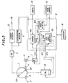
- FIG. 3 is a block diagram showing the essential parts of the structure for a recording and/or reproducing apparatus of an embodiment of the present invention;
- FIGS 4(a) to 4(f) are timing charts illustrating the servo operation of the servo circuit of the recording and/or reproducing apparatus, wherein FIG. 4(a) is a waveform diagram showing a frequency signal DFG from a drum driving motor, FIG. 4(b) is a waveform diagram showing a reference position phase pulse outputted from the drum driving motor, FIG. 4(c) is a waveform diagram showing a switching pulse for head changeover, FIG. 4(d) is a waveform diagram showing a reproducing signal read-out by the head, FIG. 4(e) is a waveform diagram showing a TATF signal and FIG. 4(f) is a waveform diagram showing a count value of a counter;
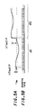
- FIG. 5(a) and FIG. 5(b) are views explaining the servo circuit operation, wherein FIG. 5(a) is a waveform diagram showing changes in the measured value when the average height of the tracks changes and FIG. 5(b) is a waveform diagram showing the timing of the measuring operation for obtaining the measured value; and FIG. 6 is a flowchart showing a processing for the servo circuit.
- The following is a detailed description with reference to the drawings of a recording and/or reproducing apparatus for a tape-shaped recording medium for the present invention. The embodiment in the following is described with the example of a recording and/or reproducing apparatus taking a magnetic tape as the tape-shaped recording medium.
- FIG. 3 is a view showing the structure of the essential parts a recording and/or reproducing apparatus for recording digital data to and reproducing digital data from a magnetic tape. A
rotational drum 1 is rotationally driven by adrum driving motor 8. On thedrum 1, twomagnetic heads - A magnetic tape 3 is then pulled out from a tape cassette not shown in the drawing by a pair of loading pins 4 and wrapped around the outer periphery of the
rotational drum 1 to an angular extent of 90°. The magnetic tape 3 has a plurality of inclined tracks, which are recorded information signals such as digital data for a computer or the like. Each track is composed of a plurality of blocks which have a sync signal. In other words, the infirmation signal is recorded on the track in the block unit. The sync signal is used the TATF signal above-mentioned. The magnetic tape 3 is pressed against a capstan 5 by apinch roller 6 and is transported at a speed corresponding to the rotations of the capstan 5 by thepinch roller 6 and the capstan 5. The capstan 5 is rotatably driven by acapstan motor 7. - Tracks of the magnetic tape 3 are alternately scanned by the
magnetic heads RF amplifier 9 through a rotary transformer not shown in the drawings. A signal outputted from theRF amplifier 9 is supplied to a reproducingprocessor 10. The reproducingprocessor 10 then performs prescribed demodulation, error correction and de-interleaving processes on the output signal from theRF amplifier 9 and supplies the output as reproducing data through anoutput terminal 16. The output signal of theRF amplifier 9 is also supplied to asynchronization detector 11 and a synchronization pattern within the track TATF signal is detected. Aservo circuit 12 performs servo control for rotation of thecapstan driving motor 7 and thedrum driving motor 8. - The
servo circuit 12 is composed of ameasurer 12a, acomparator 12b, adrive signal generator 12c and areference signal re-writer 12d, to be described later. At theservo circuit 12, a detection signal indicating that the synchronization pattern for the TATF signal from thesynchronization detector 11 is inputted to themeasurer 12a and a frequency signal CFG corresponding to the rotational velocity are provided from an FG (frequency generator) that is provided at thecapstan driving motor 7. The frequency signal CFG is provided to thedrive signal generator 12c and is used to control thecapstan driving motor 7. A frequency signal DFG from an FG provided at thedrum driving motor 8 and a reference phase position pulse DPG from a PG (pulse generator) are provided to theservo circuit 12. The pulse DPG is provided to themeasurer 12a to be used in the generation of a measured value Ts(U) to be described later. The frequency signal DFG is provided to thedrive signal generator 12c and is used for controlling the driving of thedrum driving motor 8. Acounter 13 used for measuring time is constructed from, for example, a self-propelled counter, with the count value at each moment being provided to theservo circuit 12. Areference value memory 14 is comprised of a memory that is at least capable of being re-written with data such as an S-RAM or EEP-ROM, on which a reference value T0 for the capstan servo is recorded. - A
controller 15 is composed of a microcomputer etc. and controls the operation of each of the parts of the recording and/or reproducing apparatus including theservo circuit 12. - Although the recording system circuit is not shown in FIG. 3, the
servo circuit 12 performs a constant rotational speed servo operation based on the frequency signals CFG and DFG with regards to thedrum driving motor 8 and thecapstan diving motor 7 at the time of recording. With regards to thedrum driving motor 8, theservo circuit 12 detects the rotational phase position of therotational drum 1 from the reference phase position pulse DPG provided to thedrive signal generator 12c and detects the rotational speed from the frequency signal DFG. Thedrive signal generator 12c of theservo circuit 12 compares the reference speed information and the rotational speed information to obtain speed error information. In response to this speed error information the rotational driving power as the driving signal is then adjusted and provided to themotor 8 to be driven at a constant velocity. Thedrive signal generator 12c also compares rotational speed information, which is obtained from the frequency signal CFG provided from thecapstan driving motor 7, with the reference speed information to generate speed error information. The rotational driving power as the driving signal is then generated on the basis of the speed error information and is supplied to thecapstan motor 7 which is thus driven at a constant rotational speed. Theservo circuit 12 also performs a constant rotational speed servo for thedrum driving motor 8 during the reproduction, while servo control including tracking adjustment is performed for thecapstan driving motor 7. - For the
capstan driving motor 7, a tacking control operation is performed by using the TATF signal on the basis of the rotational speed (for example, 2000 rpm) of thedrum driving motor 8 during the reproduction. This is briefly described using FIGS. 4(a) through 4(f). FIG. 4(a) shows the frequency signal DFG from thedrum driving motor 8, FIG. 4(b) shows the reference phase position pulse DPG from thedrum driving motor 8, and FIG. 4(c) shows the switching pulse providing the changeover timing for themagnetic heads magnetic head 2A and track data SB is read as reproducing data by themagnetic head 2B. A synchronization pattern for the TATF signal is detected at thesynchronization detector 11 for the track data SA and SB, and the detected timing signal based on the TATF signal as shown in FIG. 4(e) is inputted to themeasurer 12a of theservo circuit 12. FIG. 4(f) schematically shows the count value for thecounter 13. - In the tracking control operation employing the TATF signal shown in FIGS. 2(a) and 2(b), the time from the magnetic head being at a certain reference phase position at a certain point in time to the time when the TATF signal is read is measured and an servo error value is obtained by comparing this measured value with a reference value. Regarding the measuring operation of the
measurer 12a, the count value of thecounter 13 is read-in at the timing T1A of the reference phase position pulse DPG of FIG. 4(b) and the count value of thecounter 13 is read-in at the timing T2A when the TATF detection signal of FIG. 4(e) is obtained. Themeasurer 12a then subtracts the count value for the timing T2A from the count value for the timing T1A and a measuring value Ts(U) is generated. A reference value T0 is measured beforehand as the value that the measured value Ts(U) must have and this reference value T0 is stored in thereference value memory 14. The measured value Ts(U) obtained by themeasurer 12a is then compared at thecomparator 12b with the reference value T0 read-out from thememory 14 and the resulting difference is then taken as error information. The output of thecomparator 12b as the error information is provided to thedrive signal generator 12c. At thedrive signal generator 12c, the drive signal provided to thecapstan driving motor 7 is corrected based on the output from thecomparator 12b and the corrected drive signal is supplied to thecapstan driving motor 7. As a result, the relative speed of thedrum driving motor 8 and thecapstan driving motor 7 can be adjusted so as to obtain good tracking conditions. - If the average height of the tracks varies as shown in FIG. 1, the servo operation in a tracking control method employing this kind of TATF signal cannot provide normal operation. In this embodiment, however, normal operation can be continued in accordance with these kind of height variations. In order to achieve this, the
servo circuit 12 updates the reference value T0 in accordance with an operation for detecting changes the average height. The process is described using FIGS. 5(a), 5(b) and 6. FIG. 5(a) shows a change in the measured value Ts(U) when the average height of the tracks fluctuate in the regions AR1 and AR2 shown in FIG. 1. FIG. 5(b) shows the timing of the operation for measuring the measured value Ts(U). For example, in considering only the region AR1, the measured value Ts(U) fluctuates due to jitter of the rotational drum etc. in the way shown in FIG. 5(a) even when there are no fluctuations in the average height of the track. The operation for detecting changes in the average height of the tracks must therefore be carried out reliably so as to reject fluctuations due to jitter of the rotational drum. In this embodiment, changes in the average height of the tracks can therefore be detected while excluding fluctuations due to jitter of the rotational drum. - In the flowchart in FIG. 6, step F100 shows the operation for measuring the reference value T0 beforehand. Here, the measured reference value T0 is stored in the
reference value memory 14 and is used in an error value calculation during the reproduction. The process in step F101 onwards is proceeded with at theservo circuit 12 during the reproduction. First, an observation is made with the reference phase position pulse DPG to determine whether or not therotational drum 1 has reached the reference phase position. This is carried out by a controller for theservo 12 that is not shown in the drawings or by thecontroller 15. When the rotational drum has reached the reference phase position, the value of thecounter 13 at this time is read-in at themeasurer 12a and held as the time T1 (F102). Theservo 12 then waits for the TATF detection signal to be provided from the synchronization detector 11 (F103). When a detection signal is provided from thesynchronization detector 11, the value of the counter at this time is read-in and held as the time T2 (F104). When the times T1 and T2 are read-in, themeasurer 12a calculates (T2 - T1) and the result is outputted as the measurement value Ts(U) (F105). The value measured previously Ts(U-1) is then subtracted from the current measured value Ts(U) at thereference value re-writer 12d and the difference is taken as the deviation ΔTs(U) in the measured value (F106). Thereference value re-writer 12d then compares the absolute value of the deviation ΔTs(U) with a prescribed value q (F107). The value q is set to be a value greater than the sum of the fluctuation of the measured value Ts(U) due to jitter of the rotating drum and the maximum credible value of variation of the measured value Ts(U) due to the change in the height of track taken as the measuring target. That is, the prescribed value q is taken as a threshold value for determining whether the deviation ΔTs(U) is due to the influence of jitter of rotational drum etc. or due to variation in the track height. For example, as shown by the measured values within the region AR1 in FIG. 5(a), the absolute value of the deviation ΔTs(U), that is the difference due to the influence of jitter of the rotational drum etc. between the currently measured value Ts(U) and the previously measured value Ts(U-1), is comparatively small and is determined to be smaller than the prescribed value q. - On the other hand, with the boundary portion of the regions AR1 and AR2 i.e. the case where the current measured value Ts(U) is the value measured for the track for the region AR2 and the previously measured value Ts(U-1) is the measured value for the track for the region AR1, and the average track height in the region AR1 changes in the region AR2 as shown in FIG. 1, the value for the deviation ΔTs(U-1) becomes large as shown in FIG. 5(a) and the absolute value of the deviation ΔTs(U) is determined to be larger than the prescribed value q. When it is determined by the
reference value re-writer 12d in step F107 that the absolute value of the deviation ΔTs(U) is smaller than the prescribed value q, then the average height of the tracks at this time is not changed i.e. a normal servo operation is being executed. The difference between the measured value Ts(U) and the reference value T0 is therefore outputted at thecomparator 12b as the servo error value e(u) (F109). This servo error value e(u) is provided to thedrive signal generator 12c and a servo operation is executed for the capstan driving motor 7 (F110). The current measured value Ts(U) is then held in thereference value re-writer 12d or a memory within theservo circuit 12 as the previous measured value Ts(U-1) for the detection in next time (F111) and the process returns to step F101. - On the other hand, when it is determined at the
reference value re-writer 12d that the absolute value of the deviation ΔTs(U) is larger than the prescribed value q, it is determined that the average height of the tracks has changed at this time. In this case, a normal servo operation cannot be executed with the prior reference value T0. A process of updating the reference value T0 is therefore carried out in step F108 by thereference value re-writer 12d. In the updating process for thereference value re-writer 12d, the new reference value T0 is taken to be the sum of the prior reference value T0 and the deviation ΔTs(U). As the new reference value T0, for example, the current measured value Ts(U) may be taken without modification. However, as in this embodiment, the adding of the deviation ΔTs(U) to the prior reference value T0 may be taken for minimizing influence of jitter. When a new value is calculated at thereference value rewriter 12d, then the value is written into thereference value memory 14. - After this, in the same way as before, the current measured value Ts(U) is then held in the
reference value re-writer 12d or a memory within theservo circuit 12 as the previous measured value Ts(U-1) for the detection in next time (F111) and the process returns to step F101. After this, if the process proceeds to step F109, servo control is executed using the new reference value T0. After the reference value T0 has been updated, a more suitable reference value may be searched with the reproduction being continued. In the embodiment described above, even if the average height of the tracks can be found varies, the variation is detected to set-up a new reference value for being able to continue a servo operation employing a tracking control method using a TATF signal. There will therefore no abnormal tracking control employing a TATF signal that makes reproduction impossible and it will no longer be necessary re-wind the tape for performing a re-try operation in the case that the reproduction is not possible. The present invention is, however, by no means limited to the above embodiments, and various modifications that remain within the scope of the present invention are possible. - In this embodiment, a TATF signal was detected for carrying out servo control i.e. tracking control operation. However, in the case that track formats have other specific patterns, other signals may be detected for measuring the timing and the similar servo operation may be carried out. The present invention may also be broadly applied to tape recording and/or reproducing apparatus using helical scanning methods such as digital data recording and/or reproducing apparatus, a digital audio data recording and /or reproducing apparatus and 8 millimeter video recorders etc.
Claims (17)
- A controlling apparatus for a tape-shaped recording medium having information signals and information for controlling transporting speed of the tape-shaped recording medium being recorded on a plurality of slanted tracks on the tape-shaped recording medium, said controlling apparatus comprising:a rotational drum provided with at least one head;tape transporting means for transporting the tape-shaped recording medium at a prescribed speed;andcontrol means for controlling a relative speed of a transporting speed of the tape-shaped recording medium by said tape transporting means and a peripheral speed of said rotational drum, said control means comparing a value of measured time duration, which is from a time when said head passes a reference phase position of said head within one rotation of said rotational drum to a time when said head starts to reproduce information for controlling the transporting speed recorded on the tape-shaped recording medium, with a reference value, controlling the relative speed on the basis of comparison results, and further determining whether or not a difference between the value of measured time duration, which is from a time when said head passes a reference phase position of said head within one rotation of said rotational drum to the time when said head starts to reproduce information for controlling the transporting speed recorded on the tape-shaped recording medium, and the reference value falls within a prescribed range.
- A controlling apparatus for a tape-shaped recording medium according to claim 1, wherein said control means comprisescalibrating means which determines whether or not a difference between the value of measured time duration, which is from the time when said head passes a reference phase position of said head within one rotation of said rotational drum to the time when the head starts to reproduce information for controlling the transporting speed recorded on the tape-shaped recording medium, and the reference value falls within a prescribed range, and calibrates the reference value when a determination result exceeds the prescribed scope.
- A controlling apparatus for a tape-shaped recording medium according to claim 2, wherein said calibrating means calibrates the reference value on the basis of a difference between a current value and a previous value of measured time durations from the time when said head passes the reference phase position of said head within one rotation of said rotational drum to the time when said head starts to reproduce information for controlling the transporting speed recorded on the tape-shaped recording medium.
- A controlling apparatus for a tape-shaped recording medium according to claim 2, said apparatus further comprises a reference value setting means for setting a new reference value by adding the value for the difference between the current measured value and the previous measured value to the reference value when said calibrating means determines that the reference value becomes inappropriate for generating a servo control signal.
- A controlling apparatus for a tape-shaped recording medium according to claim 4, said apparatus further comprises storage means for storing the reference value which is re-written by said calibrating means on the basis of the determination result.
- A controlling apparatus for a tape-shaped recording medium according to claim 2, wherein said control means further comprises determining means which compares a value of measured time duration, which is from the time when said head passes a reference phase position of said head within one rotation of said rotational drum to the time when said head starts to reproduce information for controlling the transporting speed recorded on the tape-shaped recording medium, and a reference value, and determines whether or not comparison results fall within the prescribed range.
- A method of controlling tracking for a tape-shaped recording medium having information signals and information for controlling transporting speed of the tape-shaped recording medium being recorded on a plurality of oblique tracks on the tape-shaped recording medium, said method comprising the steps of:comparing a value of measured time duration, which is from a time when a head passes a reference phase position of a head within one rotation of a rotational drum provided with at least one head to a time when said head starts to reproduce information for carrying out tracking control recorded on the tape-shaped recording medium, with a reference value;determining whether or not the difference between the value of measured time duration, which is from the time when said head passes the reference phase position of said head within one rotation of said rotational drum to the time when said head starts to reproduce a signal for carrying out tracking control recorded on the tape-shaped recording medium, and the reference value falls within a prescribed range; andcontrolling the transporting speed of the tape-shaped recording medium and the relative rotational speed of the transporting speed of the tape-shaped recording medium and a peripheral speed of said rotational drum on the basis of the comparison results when the determination result falls within the prescribed range.
- A method of controlling tracking for a tape-shaped recording medium according to claim 7, wherein the reference value is calibrated when the determination result falls outside the prescribed range.
- A method of controlling tracking for a tape-shaped recording medium according to claim 8, wherein the reference value is calibrated on the basis of a difference between a current value and a previous value of measured time durations from the time when said head passes the reference phase position of said head within one rotation of said rotational drum to the time when said head starts to reproduce information for carrying out tracking control recorded on the tape-shaped recording medium.
- A method of controlling tracking for a tape-shaped recording medium according to claim 7, wherein the reference value is calibrated and the relative speed is controlled on the basis of the calibrated reference value when the determination result falls outside the prescribed range.
- A method of controlling tracking for a tape-shaped recording medium according to claim 10, wherein the reference value is calibrated on the basis of a difference between a current value and a previous value of measured time durations from the time when said head passes the reference phase position of said head within one rotation of the rotational drum to the time when the head starts to reproduce information for carrying out tracking control recorded on the tape-shaped recording medium.
- A controlling apparatus for a tape-shaped recording medium having information signals and information for controlling transporting speed of the tape-shaped recording medium being recorded at a plurality of slanted tracks on the tape-shaped recording medium, said controlling apparatus comprising:a rotational drum provided with at least one head, said rotational drum having a tape-shaped recording medium being would around for recording information signals and information for carrying out tracking control on the tape-shaped recording medium and reading out information signals and information for carrying out tracking control being recorded on the tape-shaped recording medium by said head;tape transporting means for transporting the tape-shaped recording medium at a prescribed speed; andcontrol means for controlling a relative speed of a transporting speed of the tape-shaped recording medium by said tape transporting means and a peripheral speed of said rotational drum, said control means comparing value of measured time duration, which is from a time when said head passes a reference phase position of the head within one rotation of said rotational drum to the time when said head starts to reproduce a signal for controlling tracking control information recorded on the tape-shaped recording medium, with a reference value, controlling the relative speed on the basis of comparison results, determining whether or not a difference between the value of measured time duration, which is from a time when said head passes a reference phase position of said head within one rotation of said rotational drum to the time when said head reproduce information for carrying out tracking control recorded on the tape-shaped recording medium, and the reference value falls within a prescribed range, and further controlling the relative speed on the basis of the comparison results when the comparison results fall within the prescribed range.
- A controlling apparatus for a tape-shaped recording medium according to claim 12, wherein said control means comprises calibrating means which determines whether or not a difference between the value of measured time duration, which is from the time when said head passes a reference phase position of said head within one rotation of said rotational drum to the time when said head starts to reproduce a signal for carrying out tracking control recorded on the tape-shaped recording medium, and the reference value falls within a prescribed range, and calibrates the reference value when a determination result exceeds the prescribed range.
- A controlling apparatus for a tape-shaped recording medium according to claim 13, wherein said calibrating means calibrates the reference value on the basis of a difference between a current value and a previous value of measured the time durations from the time when said head passes the reference phase position of said head within one rotation of said rotational drum to the time when said head starts to reproduce information for carrying out tracking control recorded on the tape-shaped recording medium.
- A controlling apparatus for a tape-shaped recording medium according to claim 12, said apparatus further comprises a reference value setting means for setting a new reference value by adding the value for the difference between the current measured value and the previous measured value to the reference value when said calibrating means determines that the reference value becomes inappropriate for generating a servo control signal.
- A controlling apparatus for a tape-shaped recording medium according to claim 15, said apparatus further comprises storage means for storing the reference value which is re-written by said calibrating means on the basis of the determination result.
- A controlling apparatus for a tape-shaped recording medium according to claim 13, wherein said control means further comprises determining means which compares a value of measured time duration, which is from the time when said head passes a reference phase position of said head within one rotation of said rotational drum to the time when said head starts to reproducing information for carrying out tracking control recorded on the tape-shaped recording medium, and a reference value, and determines whether or not comparison results fall within the prescribed range.
Applications Claiming Priority (3)
| Application Number | Priority Date | Filing Date | Title |
|---|---|---|---|
| JP6340235A JPH08185652A (en) | 1994-12-29 | 1994-12-29 | Servo device |
| JP34023594 | 1994-12-29 | ||
| JP340235/94 | 1994-12-29 |
Publications (3)
| Publication Number | Publication Date |
|---|---|
| EP0720164A2 true EP0720164A2 (en) | 1996-07-03 |
| EP0720164A3 EP0720164A3 (en) | 1997-10-15 |
| EP0720164B1 EP0720164B1 (en) | 2001-10-24 |
Family
ID=18335002
Family Applications (1)
| Application Number | Title | Priority Date | Filing Date |
|---|---|---|---|
| EP95309492A Expired - Lifetime EP0720164B1 (en) | 1994-12-29 | 1995-12-28 | Controlling apparatus and method of controlling tracking for tape-shaped recording medium |
Country Status (6)
| Country | Link |
|---|---|
| US (1) | US5959799A (en) |
| EP (1) | EP0720164B1 (en) |
| JP (1) | JPH08185652A (en) |
| KR (1) | KR960025480A (en) |
| CN (1) | CN1143797A (en) |
| DE (1) | DE69523430T2 (en) |
Cited By (3)
| Publication number | Priority date | Publication date | Assignee | Title |
|---|---|---|---|---|
| EP0831476A1 (en) * | 1996-09-24 | 1998-03-25 | Hewlett-Packard Company | Methods and apparatus for controlling tape drive read circuitry operation |
| GB2446183A (en) * | 2007-01-31 | 2008-08-06 | Hewlett Packard Development Co | Controlling motion of storage media |
| GB2461899A (en) * | 2008-07-17 | 2010-01-20 | Hewlett Packard Development Co | Appending data to tape with track position difference information |
Families Citing this family (10)
| Publication number | Priority date | Publication date | Assignee | Title |
|---|---|---|---|---|
| WO1997033279A1 (en) * | 1996-03-05 | 1997-09-12 | Sony Corporation | Tracking controller for a tape-like recording medium |
| US6101061A (en) * | 1997-10-01 | 2000-08-08 | Seagate Technology, Inc. | Methods and apparatus for calibration of a rotating scanner to a plurality of data track groups recorded on a tape |
| US6072653A (en) * | 1997-10-01 | 2000-06-06 | Seagate Technology, Inc. | Methods and apparatus for calibration of a rotating scanner to a track recorded on a tape |
| JP3417269B2 (en) * | 1997-10-03 | 2003-06-16 | ティアック株式会社 | Servo control device and information storage device |
| JPWO2002101739A1 (en) * | 2001-06-12 | 2004-09-30 | 松下電器産業株式会社 | Magnetic recording / reproducing device |
| US7919726B2 (en) * | 2002-11-29 | 2011-04-05 | Semiconductor Energy Laboratory Co., Ltd. | Laser irradiation apparatus, laser irradiation method, and method for manufacturing a semiconductor device |
| KR100594246B1 (en) * | 2004-02-06 | 2006-06-30 | 삼성전자주식회사 | Method and apparatus for compensating servo timing jitter and disc drive using the same |
| JP2006178374A (en) * | 2004-12-24 | 2006-07-06 | Brother Ind Ltd | Image forming apparatus |
| WO2007023553A1 (en) * | 2005-08-25 | 2007-03-01 | Hitachi Zosen Corporation | Alignment device for vacuum deposition |
| CN111833910B (en) * | 2019-04-23 | 2023-11-03 | 鸿富锦精密工业(武汉)有限公司 | Mechanical hard disk protection method and electronic device |
Citations (7)
| Publication number | Priority date | Publication date | Assignee | Title |
|---|---|---|---|---|
| GB2137853A (en) * | 1983-04-06 | 1984-10-10 | Ampex | System and method for synchronization of rotary head magnetic recording/reproducing devices |
| JPS63167477A (en) * | 1986-12-27 | 1988-07-11 | Pioneer Electronic Corp | Magnetic recording and reproducing device |
| GB2217051A (en) * | 1988-04-07 | 1989-10-18 | Sony Corp | A servo system for a motor |
| JPH0224874A (en) * | 1988-07-14 | 1990-01-26 | Sony Corp | Magnetic recorder |
| JPH0265685A (en) * | 1988-08-26 | 1990-03-06 | Sanyo Electric Co Ltd | Phase servo device |
| JPH03203853A (en) * | 1989-12-30 | 1991-09-05 | Sony Corp | Rotary head type magnetic recorder |
| EP0671735A2 (en) * | 1994-03-08 | 1995-09-13 | Hewlett-Packard Limited | Methods and apparatus for controlling motion of recording media |
Family Cites Families (6)
| Publication number | Priority date | Publication date | Assignee | Title |
|---|---|---|---|---|
| US3931639A (en) * | 1974-07-12 | 1976-01-06 | International Business Machines Corporation | Transverse track location device with calibrated stepper motor |
| US3964094A (en) * | 1974-11-07 | 1976-06-15 | International Business Machines Corporation | Servo information pattern for rotating head magnetic tape unit independent of amplitude |
| JPS59501765A (en) * | 1982-09-17 | 1984-10-18 | アムペツクス コ−ポレ−シヨン | Improved automatic head position tracking servo for rotating head magnetic tape recording and reproducing equipment |
| US4951162A (en) * | 1986-11-06 | 1990-08-21 | Canon Kabushiki Kaisha | Tracking control system with pilot signal phase setting circuitry |
| JP2638114B2 (en) * | 1988-08-29 | 1997-08-06 | ソニー株式会社 | Tracking control apparatus and method |
| JP2785400B2 (en) * | 1989-12-15 | 1998-08-13 | ソニー株式会社 | Tracking control device |
-
1994
- 1994-12-29 JP JP6340235A patent/JPH08185652A/en not_active Withdrawn
-
1995
- 1995-12-28 DE DE69523430T patent/DE69523430T2/en not_active Expired - Fee Related
- 1995-12-28 US US08/580,517 patent/US5959799A/en not_active Expired - Fee Related
- 1995-12-28 EP EP95309492A patent/EP0720164B1/en not_active Expired - Lifetime
- 1995-12-29 KR KR1019940067692A patent/KR960025480A/en not_active Application Discontinuation
- 1995-12-29 CN CN95113182A patent/CN1143797A/en active Pending
Patent Citations (7)
| Publication number | Priority date | Publication date | Assignee | Title |
|---|---|---|---|---|
| GB2137853A (en) * | 1983-04-06 | 1984-10-10 | Ampex | System and method for synchronization of rotary head magnetic recording/reproducing devices |
| JPS63167477A (en) * | 1986-12-27 | 1988-07-11 | Pioneer Electronic Corp | Magnetic recording and reproducing device |
| GB2217051A (en) * | 1988-04-07 | 1989-10-18 | Sony Corp | A servo system for a motor |
| JPH0224874A (en) * | 1988-07-14 | 1990-01-26 | Sony Corp | Magnetic recorder |
| JPH0265685A (en) * | 1988-08-26 | 1990-03-06 | Sanyo Electric Co Ltd | Phase servo device |
| JPH03203853A (en) * | 1989-12-30 | 1991-09-05 | Sony Corp | Rotary head type magnetic recorder |
| EP0671735A2 (en) * | 1994-03-08 | 1995-09-13 | Hewlett-Packard Limited | Methods and apparatus for controlling motion of recording media |
Non-Patent Citations (4)
| Title |
|---|
| PATENT ABSTRACTS OF JAPAN vol. 012, no. 439 (P-788), 18 November 1988 & JP 63 167477 A (PIONEER ELECTRONIC CORP), 11 July 1988, * |
| PATENT ABSTRACTS OF JAPAN vol. 014, no. 169 (P-1032), 30 March 1990 & JP 02 024874 A (SONY CORP), 26 January 1990, * |
| PATENT ABSTRACTS OF JAPAN vol. 014, no. 241 (E-0931), 22 May 1990 & JP 02 065685 A (SANYO ELECTRIC CO LTD), 6 March 1990, * |
| PATENT ABSTRACTS OF JAPAN vol. 015, no. 477 (P-1283), 4 December 1991 & JP 03 203853 A (SONY CORP), 5 September 1991, * |
Cited By (7)
| Publication number | Priority date | Publication date | Assignee | Title |
|---|---|---|---|---|
| EP0831476A1 (en) * | 1996-09-24 | 1998-03-25 | Hewlett-Packard Company | Methods and apparatus for controlling tape drive read circuitry operation |
| GB2446183A (en) * | 2007-01-31 | 2008-08-06 | Hewlett Packard Development Co | Controlling motion of storage media |
| US7813069B2 (en) | 2007-01-31 | 2010-10-12 | Hewlett-Packard Development Company, L.P. | Method and apparatus for controlling motion of storage media |
| GB2446183B (en) * | 2007-01-31 | 2011-07-20 | Hewlett Packard Development Co | Method and apparatus for controlling motion of storage media |
| GB2461899A (en) * | 2008-07-17 | 2010-01-20 | Hewlett Packard Development Co | Appending data to tape with track position difference information |
| US7911727B2 (en) | 2008-07-17 | 2011-03-22 | Hewlett-Packard Development Company, L.P. | Controlling motion of storage media |
| GB2461899B (en) * | 2008-07-17 | 2011-12-21 | Hewlett Packard Development Co | Controlling motion of storage media |
Also Published As
| Publication number | Publication date |
|---|---|
| KR960025480A (en) | 1996-07-20 |
| DE69523430D1 (en) | 2001-11-29 |
| DE69523430T2 (en) | 2002-06-27 |
| US5959799A (en) | 1999-09-28 |
| JPH08185652A (en) | 1996-07-16 |
| CN1143797A (en) | 1997-02-26 |
| EP0720164A3 (en) | 1997-10-15 |
| EP0720164B1 (en) | 2001-10-24 |
Similar Documents
| Publication | Publication Date | Title |
|---|---|---|
| EP0720164B1 (en) | Controlling apparatus and method of controlling tracking for tape-shaped recording medium | |
| US4982295A (en) | Method for centering a read/write head of a magnetic data storage apparatus on a track of a magnetic disk | |
| US4689706A (en) | Apparatus and method for adjusting the respective positions of a magnetic head and video information along a magnetic track | |
| US4768105A (en) | Apparatus for editing a video signal | |
| US5546247A (en) | Tracking control apparatus | |
| US5490017A (en) | Signal reproducing apparatus | |
| US5677807A (en) | Method and apparatus for generating a control signal | |
| US5936791A (en) | Helical scan data recording and playback method and apparatus wherein reference helical tracks preceding data recording area on magnetic tape are played back before recording or playback of target data | |
| US5477399A (en) | Programmable tension control of a variable speed recorder | |
| US5500775A (en) | Data recording and reproducing apparatus | |
| US5255134A (en) | Auto-tracking system for magnetic recording/reproducing apparatus | |
| US5760988A (en) | Tracking method and apparatus used in helical scan magnetic recording/reproducing system | |
| JP2805652B2 (en) | Rotating head type magnetic recording device | |
| JPH1011844A (en) | Auto-tracking device | |
| US5589997A (en) | Tracking control method and apparatus for video recorder which adds a combined first and second tracking error signal to the next tracking error signal | |
| JPH0836811A (en) | Tracking controller | |
| KR0176481B1 (en) | Tracking device for a video cassette recorder | |
| JP3484967B2 (en) | Magnetic recording / reproducing device | |
| US6282048B1 (en) | Tracking control method and apparatus for controlling capstan motor speed | |
| KR0170258B1 (en) | Capstan motor control method of vcr | |
| JP2705523B2 (en) | Tracking control device | |
| JPH0652605A (en) | Tape carrier motor controller | |
| JPH069093B2 (en) | Tracking method for magnetic reproducing device | |
| JPH05166259A (en) | Magnetic recording and reproducing device | |
| EP1209675A1 (en) | Head switching control apparatus for a magnetic tape recorder |
Legal Events
| Date | Code | Title | Description |
|---|---|---|---|
| PUAI | Public reference made under article 153(3) epc to a published international application that has entered the european phase |
Free format text: ORIGINAL CODE: 0009012 |
|
| AK | Designated contracting states |
Kind code of ref document: A2 Designated state(s): DE FR GB |
|
| PUAL | Search report despatched |
Free format text: ORIGINAL CODE: 0009013 |
|
| AK | Designated contracting states |
Kind code of ref document: A3 Designated state(s): DE FR GB |
|
| 17P | Request for examination filed |
Effective date: 19980324 |
|
| 17Q | First examination report despatched |
Effective date: 19990713 |
|
| GRAG | Despatch of communication of intention to grant |
Free format text: ORIGINAL CODE: EPIDOS AGRA |
|
| GRAG | Despatch of communication of intention to grant |
Free format text: ORIGINAL CODE: EPIDOS AGRA |
|
| GRAH | Despatch of communication of intention to grant a patent |
Free format text: ORIGINAL CODE: EPIDOS IGRA |
|
| GRAH | Despatch of communication of intention to grant a patent |
Free format text: ORIGINAL CODE: EPIDOS IGRA |
|
| GRAA | (expected) grant |
Free format text: ORIGINAL CODE: 0009210 |
|
| AK | Designated contracting states |
Kind code of ref document: B1 Designated state(s): DE FR GB |
|
| REF | Corresponds to: |
Ref document number: 69523430 Country of ref document: DE Date of ref document: 20011129 |
|
| PGFP | Annual fee paid to national office [announced via postgrant information from national office to epo] |
Ref country code: FR Payment date: 20011212 Year of fee payment: 7 |
|
| PGFP | Annual fee paid to national office [announced via postgrant information from national office to epo] |
Ref country code: GB Payment date: 20011227 Year of fee payment: 7 |
|
| REG | Reference to a national code |
Ref country code: GB Ref legal event code: IF02 |
|
| PGFP | Annual fee paid to national office [announced via postgrant information from national office to epo] |
Ref country code: DE Payment date: 20020109 Year of fee payment: 7 |
|
| ET | Fr: translation filed | ||
| PLBE | No opposition filed within time limit |
Free format text: ORIGINAL CODE: 0009261 |
|
| STAA | Information on the status of an ep patent application or granted ep patent |
Free format text: STATUS: NO OPPOSITION FILED WITHIN TIME LIMIT |
|
| 26N | No opposition filed | ||
| PG25 | Lapsed in a contracting state [announced via postgrant information from national office to epo] |
Ref country code: GB Free format text: LAPSE BECAUSE OF NON-PAYMENT OF DUE FEES Effective date: 20021228 |
|
| PG25 | Lapsed in a contracting state [announced via postgrant information from national office to epo] |
Ref country code: DE Free format text: LAPSE BECAUSE OF NON-PAYMENT OF DUE FEES Effective date: 20030701 |
|
| GBPC | Gb: european patent ceased through non-payment of renewal fee |
Effective date: 20021228 |
|
| PG25 | Lapsed in a contracting state [announced via postgrant information from national office to epo] |
Ref country code: FR Free format text: LAPSE BECAUSE OF NON-PAYMENT OF DUE FEES Effective date: 20030901 |
|
| REG | Reference to a national code |
Ref country code: FR Ref legal event code: ST |