EP0720144A1 - A system for reducing noise due to vibrations in a vehicle - Google Patents
A system for reducing noise due to vibrations in a vehicle Download PDFInfo
- Publication number
- EP0720144A1 EP0720144A1 EP95120083A EP95120083A EP0720144A1 EP 0720144 A1 EP0720144 A1 EP 0720144A1 EP 95120083 A EP95120083 A EP 95120083A EP 95120083 A EP95120083 A EP 95120083A EP 0720144 A1 EP0720144 A1 EP 0720144A1
- Authority
- EP
- European Patent Office
- Prior art keywords
- ccr
- laminar element
- actuator means
- noise
- signal
- Prior art date
- Legal status (The legal status is an assumption and is not a legal conclusion. Google has not performed a legal analysis and makes no representation as to the accuracy of the status listed.)
- Withdrawn
Links
Images


Classifications
-
- G—PHYSICS
- G10—MUSICAL INSTRUMENTS; ACOUSTICS
- G10K—SOUND-PRODUCING DEVICES; METHODS OR DEVICES FOR PROTECTING AGAINST, OR FOR DAMPING, NOISE OR OTHER ACOUSTIC WAVES IN GENERAL; ACOUSTICS NOT OTHERWISE PROVIDED FOR
- G10K11/00—Methods or devices for transmitting, conducting or directing sound in general; Methods or devices for protecting against, or for damping, noise or other acoustic waves in general
- G10K11/16—Methods or devices for protecting against, or for damping, noise or other acoustic waves in general
- G10K11/175—Methods or devices for protecting against, or for damping, noise or other acoustic waves in general using interference effects; Masking sound
- G10K11/178—Methods or devices for protecting against, or for damping, noise or other acoustic waves in general using interference effects; Masking sound by electro-acoustically regenerating the original acoustic waves in anti-phase
- G10K11/1787—General system configurations
- G10K11/17879—General system configurations using both a reference signal and an error signal
- G10K11/17883—General system configurations using both a reference signal and an error signal the reference signal being derived from a machine operating condition, e.g. engine RPM or vehicle speed
-
- G—PHYSICS
- G10—MUSICAL INSTRUMENTS; ACOUSTICS
- G10K—SOUND-PRODUCING DEVICES; METHODS OR DEVICES FOR PROTECTING AGAINST, OR FOR DAMPING, NOISE OR OTHER ACOUSTIC WAVES IN GENERAL; ACOUSTICS NOT OTHERWISE PROVIDED FOR
- G10K11/00—Methods or devices for transmitting, conducting or directing sound in general; Methods or devices for protecting against, or for damping, noise or other acoustic waves in general
- G10K11/16—Methods or devices for protecting against, or for damping, noise or other acoustic waves in general
- G10K11/175—Methods or devices for protecting against, or for damping, noise or other acoustic waves in general using interference effects; Masking sound
- G10K11/178—Methods or devices for protecting against, or for damping, noise or other acoustic waves in general using interference effects; Masking sound by electro-acoustically regenerating the original acoustic waves in anti-phase
- G10K11/1781—Methods or devices for protecting against, or for damping, noise or other acoustic waves in general using interference effects; Masking sound by electro-acoustically regenerating the original acoustic waves in anti-phase characterised by the analysis of input or output signals, e.g. frequency range, modes, transfer functions
- G10K11/17821—Methods or devices for protecting against, or for damping, noise or other acoustic waves in general using interference effects; Masking sound by electro-acoustically regenerating the original acoustic waves in anti-phase characterised by the analysis of input or output signals, e.g. frequency range, modes, transfer functions characterised by the analysis of the input signals only
- G10K11/17825—Error signals
-
- G—PHYSICS
- G10—MUSICAL INSTRUMENTS; ACOUSTICS
- G10K—SOUND-PRODUCING DEVICES; METHODS OR DEVICES FOR PROTECTING AGAINST, OR FOR DAMPING, NOISE OR OTHER ACOUSTIC WAVES IN GENERAL; ACOUSTICS NOT OTHERWISE PROVIDED FOR
- G10K11/00—Methods or devices for transmitting, conducting or directing sound in general; Methods or devices for protecting against, or for damping, noise or other acoustic waves in general
- G10K11/16—Methods or devices for protecting against, or for damping, noise or other acoustic waves in general
- G10K11/175—Methods or devices for protecting against, or for damping, noise or other acoustic waves in general using interference effects; Masking sound
- G10K11/178—Methods or devices for protecting against, or for damping, noise or other acoustic waves in general using interference effects; Masking sound by electro-acoustically regenerating the original acoustic waves in anti-phase
- G10K11/1785—Methods, e.g. algorithms; Devices
- G10K11/17857—Geometric disposition, e.g. placement of microphones
-
- G—PHYSICS
- G10—MUSICAL INSTRUMENTS; ACOUSTICS
- G10K—SOUND-PRODUCING DEVICES; METHODS OR DEVICES FOR PROTECTING AGAINST, OR FOR DAMPING, NOISE OR OTHER ACOUSTIC WAVES IN GENERAL; ACOUSTICS NOT OTHERWISE PROVIDED FOR
- G10K2210/00—Details of active noise control [ANC] covered by G10K11/178 but not provided for in any of its subgroups
- G10K2210/10—Applications
- G10K2210/128—Vehicles
- G10K2210/1282—Automobiles
-
- G—PHYSICS
- G10—MUSICAL INSTRUMENTS; ACOUSTICS
- G10K—SOUND-PRODUCING DEVICES; METHODS OR DEVICES FOR PROTECTING AGAINST, OR FOR DAMPING, NOISE OR OTHER ACOUSTIC WAVES IN GENERAL; ACOUSTICS NOT OTHERWISE PROVIDED FOR
- G10K2210/00—Details of active noise control [ANC] covered by G10K11/178 but not provided for in any of its subgroups
- G10K2210/30—Means
- G10K2210/301—Computational
- G10K2210/3033—Information contained in memory, e.g. stored signals or transfer functions
-
- G—PHYSICS
- G10—MUSICAL INSTRUMENTS; ACOUSTICS
- G10K—SOUND-PRODUCING DEVICES; METHODS OR DEVICES FOR PROTECTING AGAINST, OR FOR DAMPING, NOISE OR OTHER ACOUSTIC WAVES IN GENERAL; ACOUSTICS NOT OTHERWISE PROVIDED FOR
- G10K2210/00—Details of active noise control [ANC] covered by G10K11/178 but not provided for in any of its subgroups
- G10K2210/30—Means
- G10K2210/301—Computational
- G10K2210/3041—Offline
-
- G—PHYSICS
- G10—MUSICAL INSTRUMENTS; ACOUSTICS
- G10K—SOUND-PRODUCING DEVICES; METHODS OR DEVICES FOR PROTECTING AGAINST, OR FOR DAMPING, NOISE OR OTHER ACOUSTIC WAVES IN GENERAL; ACOUSTICS NOT OTHERWISE PROVIDED FOR
- G10K2210/00—Details of active noise control [ANC] covered by G10K11/178 but not provided for in any of its subgroups
- G10K2210/30—Means
- G10K2210/321—Physical
- G10K2210/3212—Actuator details, e.g. composition or microstructure
-
- G—PHYSICS
- G10—MUSICAL INSTRUMENTS; ACOUSTICS
- G10K—SOUND-PRODUCING DEVICES; METHODS OR DEVICES FOR PROTECTING AGAINST, OR FOR DAMPING, NOISE OR OTHER ACOUSTIC WAVES IN GENERAL; ACOUSTICS NOT OTHERWISE PROVIDED FOR
- G10K2210/00—Details of active noise control [ANC] covered by G10K11/178 but not provided for in any of its subgroups
- G10K2210/30—Means
- G10K2210/321—Physical
- G10K2210/3217—Collocated sensor and cancelling actuator, e.g. "virtual earth" designs
-
- G—PHYSICS
- G10—MUSICAL INSTRUMENTS; ACOUSTICS
- G10K—SOUND-PRODUCING DEVICES; METHODS OR DEVICES FOR PROTECTING AGAINST, OR FOR DAMPING, NOISE OR OTHER ACOUSTIC WAVES IN GENERAL; ACOUSTICS NOT OTHERWISE PROVIDED FOR
- G10K2210/00—Details of active noise control [ANC] covered by G10K11/178 but not provided for in any of its subgroups
- G10K2210/30—Means
- G10K2210/321—Physical
- G10K2210/3229—Transducers
- G10K2210/32291—Plates or thin films, e.g. PVDF
Definitions
- the present invention relates in general to active vibration-reduction systems and, more specifically, relates to active systems for reducing vibrations in motor-vehicle bodywork panels.
- the object of the present invention is to provide a vibration-reduction system which solves the problem indicated above in a satisfactory manner.
- the present invention consists essentially of an active electronic system for controlling vibrations in laminar elements such as, for example, metal sheets or bodywork panels.
- a motor-vehicle bodywork panel typically of sheet metal, is indicated L.
- At least one actuator A normally of the piezoelectric type, is fitted on the panel L.
- Typically, several actuators A are fitted on the panel L.
- actuators A are controlled or driven by an electronic control unit CCR for the active control of vibrations or noise.
- the actuators A are driven by means of voltage-raising circuits EV.
- the control unit CCR is also connected to a control unit CCM which manages the internal combustion engine of the motor vehicle.
- the engine-management unit CCM transmits a signal RPM indicative of the speed of rotation of the engine to the vibration-control unit CCR by means of this connection.
- a signal of this type is now available in almost all motor vehicles currently in production.
- the system according to the present invention is in fact based on the fact that most vibrations which may be encountered in bodywork panels L are induced, directly or indirectly, by the internal combustion engine of the motor vehicle and therefore have frequencies which depend on the speed of rotation or the number of revolutions per minute, RPM, of the engine. It is thus possible to achieve a substantial reduction in the vibrations and hence in the noise induced by the engine in the bodywork panels L, even in the absence of sensors for detecting the vibrations as in systems according to the prior art.
- the system according to the present invention comprises a noise appraiser which generates one or more signals for driving the actuators A on the basis of the signal RPM indicative of the speed of rotation of the engine.
- the noise appraiser forms part of the vibration-control unit CCR and will now be described in greater detail with reference to Figure 3.
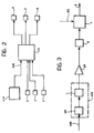
- Figure 3 shows the system according to the present invention schematically, by means of functional blocks.
- parts and elements already described with reference to Figure 1 have again been attributed the same alphanumeric references.
- the vibration-control unit CCR comprises a noise appraiser SR, mentioned above, and a processing unit C, for example, a microprocessor.
- the noise appraiser SR as stated above, generates signals for driving the actuators A on the basis of the signal RPM which it receives as an input.
- the actuators A in turn act on the bodywork L so as to minimize the vibrations induced by disturbances DIS, for example, the internal combustion engine, and hence the noise R, generated by the bodywork L.
- the vibrations induced in the bodywork L by the engine must be analyzed beforehand.
- the vibrations induced in the various bodywork panels L are therefore recorded and analyzed for all of the speeds of rotation of the engine.
- a body of data is thus collected which provides a complete picture of the vibrations induced.
- Signals suitable for reducing vibrations typically one signal for each actuator A, can be produced on the basis of these data.
- the production of these signals typically consists of the generation of a waveform corresponding to that detected, but in phase opposition, and is within the capabilities of a person in the art.
- corrective parameters may also be introduced or the waveform may be modified on the basis of experimental findings in order to optimize the noise-reduction effect.
- the waveforms may be frequency-filtered.
- the waveforms are stored in the noise appraiser SR, associated with the respective speeds of rotation of the engine.
- the noise appraiser SR has a memory area for this purpose, for example, a read-only digital memory or ROM, of a size sufficient for storing all the waveforms used by the noise appraiser SR.
- the noise appraiser SR thus outputs the waveforms corresponding to the speed of rotation of the engine derived from the signal RPM. These waveforms are transmitted to a subsequent processing unit C which generates the signals for driving the actuators A, in their final form, on the basis of these waveforms.
- the processing unit C generates the periodic signals for the actuators A on the basis of the waveforms transmitted by the noise appraiser SR and passes these periodic signals to the outputs of the control unit CCR.
- the processing unit C thus comprises digital-analog converter circuits and amplifier circuits so that it can generate analog signals which can be used directly, possibly by means of the voltage-raising circuits EV, to drive the actuators A.
- the processing unit C is also configured in a manner such that the frequency and phase of the driving signals are matched with the frequency and phase of the signal RPM in order to maximize the vibration-reduction effect.
- the processing unit C also has to receive the signal RPM, or a corresponding synchronizing signal transmitted by the noise appraiser SR.
- a signal from a phonic-wheel of the internal combustion engine may be used as the signal RPM.
- the bodywork panels L of motor vehicles of the same model are identical only in theory, it is possible to provide for a detection step for each vehicle upon completion of manufacturing operations so as to characterize the waveforms or determine their parameters individually. These individually characterized waveforms can then be stored in the read-only memory of the estimator SR. This further improves the performance of the system.
- the noise appraiser SR uses a dynamic model of the bodywork L which enables the waveforms to be produced.
- the system that is, essentially the noise appraiser SR disposed in the control unit CCR, may also be configured so as to implement the active noise-control function in addition to or instead of the vibration-control function. In fact, it should not be forgotten that the purpose of reducing vibrations is essentially to reduce the noise inside the passenger compartment of the vehicle.
- the system according to the invention which may involve some of the panels L and the actuators A, requires no modification with respect to the foregoing description.
- the only difference is in the final objective of the preliminary data-recording and analysis step which, in this case, has the purpose of reducing noise in addition to or instead of vibrations.
- the system according to the invention may also have sensors S, as shown in Figure 2, as in systems according to the prior art.
- the system thus has a feedback signal which enables the effects of the driving signals to be checked and corrected.
- Figure 4 which is similar to Figure 3 and shows the system of Figure 2 at the functional level, the feedback signal detected by the sensors S is indicative of the noise R generated by the bodywork L and is sent to the processing unit C.
- both the actuators A and the sensors S are formed of ceramic or polymeric piezoelectric material. They are generally flat in shape and in fact have very little thickness and hence little bulk and are glued to the panel L so as to be fixed firmly thereto.
- the sensors S and the actuators A will be applied to a limited number of bodywork panels L which are the primary sources of noise in the passenger compartment of a motor vehicle.
- bodywork panels L which are the primary sources of noise in the passenger compartment of a motor vehicle.
- the sensors S and the actuators A may advantageously be fitted at the same points.
- the sensor S and the actuator A may, for example, be fitted on two opposite surfaces of a panel L.
- the sensor S may be fitted on one surface of the panel L and the actuator A may be fitted on the sensor S, that is, superimposed thereon.
- the system comprises a device (not shown) for regulating gain.
- This gain-regulator operates by means of one or more suitable sensors (not shown) fitted on the bodywork L and has the function of limiting the gain of the system when it detects vibrations of very large amplitude, that is, such as to endanger the actuators A.
- the regulator may operate automatically or manually or may even switch selectively between one operating mode and the other.
- the system according to the present invention considerably reduces vibrations and noise inside a motor vehicle whilst being of very low cost.
- the noise induced by the road in the passenger compartment of a motor vehicle and transmitted from the engine by solid means can thus be reduced and at the same time the damping elements which are used at the moment can be reduced.
- the weight of the vehicle can be reduced whilst its comfort is at the same time improved.
Landscapes
- Physics & Mathematics (AREA)
- Engineering & Computer Science (AREA)
- Acoustics & Sound (AREA)
- Multimedia (AREA)
- Soundproofing, Sound Blocking, And Sound Damping (AREA)
- Vibration Prevention Devices (AREA)
- Fittings On The Vehicle Exterior For Carrying Loads, And Devices For Holding Or Mounting Articles (AREA)
Abstract
An active system for reducing vibrations in the body panels (L) of a motor vehicle comprises piezoelectric actuators (A) fitted on the panels (L) and driven by an electronic control unit (CCR) on the basis of a signal (RPM) indicative of the speed of rotation of the internal combustion engine of the motor vehicle. The system reduces vibrations, and consequently noise, inside the passenger compartment, at the same time enabling the damping elements to be reduced, whilst being of very low cost.
Description
- The present invention relates in general to active vibration-reduction systems and, more specifically, relates to active systems for reducing vibrations in motor-vehicle bodywork panels.
- Conventionally, various passive techniques have been used to reduce the level of vibrations and consequently noise produced by bodywork panels in vehicles and particularly in motor vehicles. These techniques consist essentially of applying damping elements and sound-deadening panels to the bodywork panels. These devices have the disadvantage of being bulky, heavy and quite expensive.
- Active noise-control systems have been developed to prevent these problems. In vehicles, particularly motor vehicles, these systems are used to reduce vibrations in bodywork panels so as to reduce the noise produced thereby. A system of this type is described, for example, in Italian patent application No. TO93A000577 filed in the Applicant's name on 3rd August 1993.
- In practice, these systems are based on the principle of detecting the vibrations of the panels by means of sensors and then driving actuators fitted on the panels in phase opposition in order to reduce or eliminate the vibrations. Although they are effective, these systems have the disadvantage of being very complex and expensive and, up to now, this has prevented their use in motor vehicles currently in production.
- The object of the present invention is to provide a vibration-reduction system which solves the problem indicated above in a satisfactory manner.
- According to the present invention, this object is achieved by virtue of a vibration-reduction system having the characteristics indicated in the claims which follow the present description.
- Further advantages and characteristics of the present invention will become clear from the following detailed description given with the aid of the appended drawings provided by way of non-limiting example, in which:
- Figure 1 is a schematic block diagram of an embodiment of the system according to the present invention,
- Figure 2 is a schematic block diagram of an alternative embodiment of the system according to the invention,
- Figure 3 is a schematic functional block diagram of the system of Figure 1, and
- Figure 4 is a schematic functional block diagram of the system of Figure 2.
- The present invention consists essentially of an active electronic system for controlling vibrations in laminar elements such as, for example, metal sheets or bodywork panels.
- With reference to Figure 1, a motor-vehicle bodywork panel, typically of sheet metal, is indicated L. At least one actuator A, normally of the piezoelectric type, is fitted on the panel L. Typically, several actuators A are fitted on the panel L.
- These actuators A are controlled or driven by an electronic control unit CCR for the active control of vibrations or noise. In the specific embodiment illustrated, the actuators A are driven by means of voltage-raising circuits EV. In fact, in the case of piezoelectric actuators A, it is necessary to use sufficiently high voltages, typically greater than the 12 volts normally available in a motor vehicle, to drive the actuators A.
- The control unit CCR is also connected to a control unit CCM which manages the internal combustion engine of the motor vehicle. The engine-management unit CCM transmits a signal RPM indicative of the speed of rotation of the engine to the vibration-control unit CCR by means of this connection. A signal of this type is now available in almost all motor vehicles currently in production.
- The system according to the present invention is in fact based on the fact that most vibrations which may be encountered in bodywork panels L are induced, directly or indirectly, by the internal combustion engine of the motor vehicle and therefore have frequencies which depend on the speed of rotation or the number of revolutions per minute, RPM, of the engine. It is thus possible to achieve a substantial reduction in the vibrations and hence in the noise induced by the engine in the bodywork panels L, even in the absence of sensors for detecting the vibrations as in systems according to the prior art.
- For this purpose, the system according to the present invention comprises a noise appraiser which generates one or more signals for driving the actuators A on the basis of the signal RPM indicative of the speed of rotation of the engine. Naturally, the noise appraiser forms part of the vibration-control unit CCR and will now be described in greater detail with reference to Figure 3.
- Figure 3 shows the system according to the present invention schematically, by means of functional blocks. In Figure 3, parts and elements already described with reference to Figure 1 have again been attributed the same alphanumeric references.
- As can be seen from the drawing, the vibration-control unit CCR comprises a noise appraiser SR, mentioned above, and a processing unit C, for example, a microprocessor. The noise appraiser SR, as stated above, generates signals for driving the actuators A on the basis of the signal RPM which it receives as an input. The actuators A in turn act on the bodywork L so as to minimize the vibrations induced by disturbances DIS, for example, the internal combustion engine, and hence the noise R, generated by the bodywork L.
- So that the noise appraiser SR can perform this function, the vibrations induced in the bodywork L by the engine must be analyzed beforehand. In a preliminary step, the vibrations induced in the various bodywork panels L are therefore recorded and analyzed for all of the speeds of rotation of the engine. A body of data is thus collected which provides a complete picture of the vibrations induced. Signals suitable for reducing vibrations, typically one signal for each actuator A, can be produced on the basis of these data.
- The production of these signals typically consists of the generation of a waveform corresponding to that detected, but in phase opposition, and is within the capabilities of a person in the art. In the course of this operation, corrective parameters may also be introduced or the waveform may be modified on the basis of experimental findings in order to optimize the noise-reduction effect. For example, the waveforms may be frequency-filtered.
- When they have been produced, the waveforms are stored in the noise appraiser SR, associated with the respective speeds of rotation of the engine. Naturally, the noise appraiser SR has a memory area for this purpose, for example, a read-only digital memory or ROM, of a size sufficient for storing all the waveforms used by the noise appraiser SR.
- In use, the noise appraiser SR thus outputs the waveforms corresponding to the speed of rotation of the engine derived from the signal RPM. These waveforms are transmitted to a subsequent processing unit C which generates the signals for driving the actuators A, in their final form, on the basis of these waveforms.
- In practice, the processing unit C generates the periodic signals for the actuators A on the basis of the waveforms transmitted by the noise appraiser SR and passes these periodic signals to the outputs of the control unit CCR. Typically, the processing unit C thus comprises digital-analog converter circuits and amplifier circuits so that it can generate analog signals which can be used directly, possibly by means of the voltage-raising circuits EV, to drive the actuators A.
- Moreover, the processing unit C is also configured in a manner such that the frequency and phase of the driving signals are matched with the frequency and phase of the signal RPM in order to maximize the vibration-reduction effect. For this purpose, the processing unit C also has to receive the signal RPM, or a corresponding synchronizing signal transmitted by the noise appraiser SR. In order to improve the precision and performance of the system, a signal from a phonic-wheel of the internal combustion engine may be used as the signal RPM.
- Moreover, since the bodywork panels L of motor vehicles of the same model are identical only in theory, it is possible to provide for a detection step for each vehicle upon completion of manufacturing operations so as to characterize the waveforms or determine their parameters individually. These individually characterized waveforms can then be stored in the read-only memory of the estimator SR. This further improves the performance of the system.
- Naturally, more complex techniques may be used to generate the driving signals, for example, if the noise appraiser SR uses a dynamic model of the bodywork L which enables the waveforms to be produced.
- The system, that is, essentially the noise appraiser SR disposed in the control unit CCR, may also be configured so as to implement the active noise-control function in addition to or instead of the vibration-control function. In fact, it should not be forgotten that the purpose of reducing vibrations is essentially to reduce the noise inside the passenger compartment of the vehicle.
- From this point of view, it may be necessary, in some cases, to drive the actuators A so as to produce vibrations rather than damp them, in order to eliminate or reduce noises present in the passenger compartment. However, in this case, the system according to the invention, which may involve some of the panels L and the actuators A, requires no modification with respect to the foregoing description. The only difference is in the final objective of the preliminary data-recording and analysis step which, in this case, has the purpose of reducing noise in addition to or instead of vibrations.
- The system according to the invention may also have sensors S, as shown in Figure 2, as in systems according to the prior art. The system thus has a feedback signal which enables the effects of the driving signals to be checked and corrected. As can be seen from Figure 4, which is similar to Figure 3 and shows the system of Figure 2 at the functional level, the feedback signal detected by the sensors S is indicative of the noise R generated by the bodywork L and is sent to the processing unit C.
- In an embodiment currently considered preferable, both the actuators A and the sensors S are formed of ceramic or polymeric piezoelectric material. They are generally flat in shape and in fact have very little thickness and hence little bulk and are glued to the panel L so as to be fixed firmly thereto.
- In the specific embodiment, it is envisaged that the sensors S and the actuators A will be applied to a limited number of bodywork panels L which are the primary sources of noise in the passenger compartment of a motor vehicle. These are, for example:
- the dashboard or the fireproof bulkhead,
- the floor panels, the front floor panels and the central floor panels,
- the tunnel,
- the roof panel.
- The sensors S and the actuators A may advantageously be fitted at the same points. The sensor S and the actuator A may, for example, be fitted on two opposite surfaces of a panel L. Alternatively, however, the sensor S may be fitted on one surface of the panel L and the actuator A may be fitted on the sensor S, that is, superimposed thereon.
- Moreover, in an alternative embodiment, the system comprises a device (not shown) for regulating gain. This gain-regulator operates by means of one or more suitable sensors (not shown) fitted on the bodywork L and has the function of limiting the gain of the system when it detects vibrations of very large amplitude, that is, such as to endanger the actuators A. The regulator may operate automatically or manually or may even switch selectively between one operating mode and the other.
- The system according to the present invention considerably reduces vibrations and noise inside a motor vehicle whilst being of very low cost. The noise induced by the road in the passenger compartment of a motor vehicle and transmitted from the engine by solid means can thus be reduced and at the same time the damping elements which are used at the moment can be reduced. In summary, the weight of the vehicle can be reduced whilst its comfort is at the same time improved.
- Naturally, the principle of the invention remaining the same, the details of construction and forms of embodiment may be varied widely with respect to those described and illustrated, without thereby departing from the scope of the present invention.
Claims (27)
- A system for reducing vibrations in at least one laminar element (L) of a vehicle, characterized in that it comprises, in operative combination:- piezoelectric actuator means (A) fitted on the laminar element (L) for producing mechanical stresses in the laminar element (L),- processing means (CCR) receiving a signal (RPM) indicative of the speed of rotation of an internal combustion engine of the vehicle and operatively connected to the actuator means (A) for processing the signal indicative of the speed of rotation to generate control signals for controlling the actuator means (A) in order to reduce the mechanical deformations of the laminar element (L).
- A system according to Claim 1, in which the mechanical deformations are vibrations of the laminar element (L), characterized in that the processing means (CCR) are configured for generating signals which can drive the actuator means (A) in phase opposition with the vibrations in order to reduce them.
- A system according to Claim 2, characterized in that the processing means (CCR) comprise noise appraiser means (SR) which receive the signal (RPM) indicative of the speed and are configured for generating different driving signals for the actuator means (A) for different values of the signal (RPM) indicative of the speed.
- A system according to Claim 3, characterized in that the noise appraiser means (SR) comprise memory means in which a plurality of previously-produced waveforms corresponding to a plurality of values of the signal (RPM) indicative of the speed is stored, the noise appraiser means (SR) being configured for outputting the waveforms corresponding to the input values of the signal (RPM) indicative of the speed.
- A system according to Claim 4, characterized in that the memory means comprise a read-only digital memory.
- A system according to Claim 4 or Claim 5, characterized in that the processing means (CCR) comprise a processing unit (C) which receives the waveforms as an input from the noise appraiser means (SR) and can generate periodic analog output signals for driving the actuator means (A).
- A system according to Claim 6, characterized in that the processing unit (C) comprises analog-digital converter circuits and amplifier circuits.
- A system according to Claim 7, characterized in that the processing unit (C) is configured so as to match the periodic signals with the signal (RPM) indicative of the speed with regard to phase and frequency.
- A system according to Claim 8, characterized in that the signal indicative of the speed is a signal (RPM) of a phonic-wheel of the internal combustion engine.
- A system according to Claim 9, characterized in that the waveforms are produced individually for each motor vehicle in a preliminary step.
- A system according to Claim 10, characterized in that the individually-processed waveforms are stored in the read-only memory.
- A system according to any one of Claims 1 to 11, characterized in that the processing means (CCR) are configured for controlling the actuator means (A) in order to reduce acoustic noise in a space near to the laminar element (L).
- A system according to Claim 12, characterized in that the processing means (CCR) are configured for generating signals which can drive the actuator means (A) in phase opposition with the noise, in order to reduce it.
- A system according to any one of Claims 1 to 13, characterized in that it comprises sensor means (S) fitted on the laminar element (L) and operatively connected to the processing means (CCR) in order to correct the driving signals.
- A system according to Claim 14, characterized in that it comprises gain-regulator means for limiting the amplitude of the driving signals if the sensor means (S) detect vibrations in the laminar element (L) having an intensity greater than a predetermined value.
- A system according to Claim 15, characterized in that the gain-regulator means are integrated in the processing means (CCR).
- A system according to any one of Claims 1 to 16, characterized in that it comprises voltage-raising means (EV) operatively connected to the processing means (CCR) and to the actuator means (A) for amplifying the control signals.
- A system according to Claim 17, characterized in that the voltage-raising means (EV) comprise a voltage converter circuit which can generate a voltage greater than the voltage with which it is supplied.
- A system according to any one of Claims 1 to 18, characterized in that the sensor means (S) and the actuator means (A) are glued to the laminar element (L) so as to be essentially integral therewith.
- A system according to Claim 19, characterized in that the sensor means (S) and the actuator means (A) are fitted generally on the same portion of the laminar element (L).
- A system according to Claim 19, characterized in that the sensor means (S) and the actuator means (A) are fitted on the two opposite surfaces of the laminar element (L).
- A system according to Claim 19, characterized in that the sensor means (S) and the actuator means (A) are fixed together and fitted on one surface of the laminar element (L).
- A system according to any one of Claims 1 to 22, characterized in that the actuator means (A) are made of polymeric piezoelectric material.
- A system according to any one of Claims 1 to 22, characterized in that the actuator means (A) are made of ceramic piezoelectric material.
- A system according to any one of Claims 1 to 24, characterized in that it comprises a plurality of actuator means (A) and in that the processing means comprise an electronic control unit (CCR) having a plurality of outputs.
- A system according to Claim 25, characterized in that the control unit (CCR) is produced in the form of an integrated circuit.
- A system according to any one of Claims 1 to 26, in which the laminar element (L) is a motor-vehicle bodywork panel, characterized in that the actuator means (A) are fitted on a plurality of panels (L) selected from the group constituted by:- the dashboard,- the fireproof bulkhead,- the front floor panel,- the central floor panels,- the tunnel,- the roof panel.
Applications Claiming Priority (2)
| Application Number | Priority Date | Filing Date | Title |
|---|---|---|---|
| ITTO941083 | 1994-12-28 | ||
| IT94TO001083A IT1268204B1 (en) | 1994-12-28 | 1994-12-28 | SYSTEM FOR THE REDUCTION OF NOISE DUE TO VIBRATIONS OF A VEHICLE. |
Publications (1)
| Publication Number | Publication Date |
|---|---|
| EP0720144A1 true EP0720144A1 (en) | 1996-07-03 |
Family
ID=11413015
Family Applications (1)
| Application Number | Title | Priority Date | Filing Date |
|---|---|---|---|
| EP95120083A Withdrawn EP0720144A1 (en) | 1994-12-28 | 1995-12-19 | A system for reducing noise due to vibrations in a vehicle |
Country Status (2)
| Country | Link |
|---|---|
| EP (1) | EP0720144A1 (en) |
| IT (1) | IT1268204B1 (en) |
Cited By (6)
| Publication number | Priority date | Publication date | Assignee | Title |
|---|---|---|---|---|
| EP1055841A2 (en) | 1999-05-22 | 2000-11-29 | Volkswagen Aktiengesellschaft | Method and arrangement to suppress or damp body-jitter in automotive vehicles |
| DE102004030935B3 (en) * | 2004-06-25 | 2005-09-15 | Benteler Automobiltechnik Gmbh | Vibration damping device for motor vehicle, has three actuators arranged on pitch circle in hollow cylindrical body of damping module, where longitudinal projection of actuators is aligned parallel to longitudinal projection of body |
| DE102005024412A1 (en) * | 2005-05-27 | 2006-11-30 | Volkswagen Ag | Circuit board for use in motor vehicle, has piezo unit arranged at surface point of board and formed by piezo sensor, with which oscillation frequency and amplitudes are determined by oscillation stimulation of board |
| DE102008051288A1 (en) * | 2008-10-10 | 2010-04-15 | Wilhelm Karmann Gmbh | Motor vehicle i.e. cabriolet vehicle, has actuator for changing length of support attached to base region and controlled by sensor arrangement, which is attached to body of vehicle below window parapet line |
| WO2010094786A2 (en) | 2009-02-19 | 2010-08-26 | Magna Steyr Fahrzeugtechnik Ag & Co Kg | Planar component with vibration damping |
| CN108877761A (en) * | 2017-05-10 | 2018-11-23 | Fca意大利股份公司 | The improvement of acoustic comfort in motor vehicle passenger compartment |
Citations (6)
| Publication number | Priority date | Publication date | Assignee | Title |
|---|---|---|---|---|
| FR2531023A1 (en) * | 1982-08-02 | 1984-02-03 | Peugeot | Noise attenuation device in the passenger compartment of an automobile vehicle. |
| EP0385713A2 (en) * | 1989-03-01 | 1990-09-05 | Sony Corporation | Noise reducing receiver device |
| JPH03292219A (en) * | 1990-04-09 | 1991-12-24 | Nissan Motor Co Ltd | Vibration control device for vehicle |
| EP0479367A2 (en) * | 1990-10-04 | 1992-04-08 | General Motors Corporation | Method and apparatus for attenuating engine generated noise |
| WO1992017936A1 (en) * | 1991-04-05 | 1992-10-15 | Applied Acoustic Research | Active noise control |
| GB2260874A (en) * | 1991-10-21 | 1993-04-28 | Marconi Gec Ltd | A sound control device |
-
1994
- 1994-12-28 IT IT94TO001083A patent/IT1268204B1/en active IP Right Grant
-
1995
- 1995-12-19 EP EP95120083A patent/EP0720144A1/en not_active Withdrawn
Patent Citations (6)
| Publication number | Priority date | Publication date | Assignee | Title |
|---|---|---|---|---|
| FR2531023A1 (en) * | 1982-08-02 | 1984-02-03 | Peugeot | Noise attenuation device in the passenger compartment of an automobile vehicle. |
| EP0385713A2 (en) * | 1989-03-01 | 1990-09-05 | Sony Corporation | Noise reducing receiver device |
| JPH03292219A (en) * | 1990-04-09 | 1991-12-24 | Nissan Motor Co Ltd | Vibration control device for vehicle |
| EP0479367A2 (en) * | 1990-10-04 | 1992-04-08 | General Motors Corporation | Method and apparatus for attenuating engine generated noise |
| WO1992017936A1 (en) * | 1991-04-05 | 1992-10-15 | Applied Acoustic Research | Active noise control |
| GB2260874A (en) * | 1991-10-21 | 1993-04-28 | Marconi Gec Ltd | A sound control device |
Non-Patent Citations (2)
| Title |
|---|
| PATENT ABSTRACTS OF JAPAN vol. 016, no. 129 (M - 1228) 2 April 1992 (1992-04-02) * |
| S. M. YANG ET AL.: "Vibration suppression with optimal sensor/actuator location and feedback gain", SMART MATERIALS AND STRUCTURES, vol. 2, no. 4, BRISTOL GB, pages 2332 - 239, XP000415226 * |
Cited By (9)
| Publication number | Priority date | Publication date | Assignee | Title |
|---|---|---|---|---|
| EP1055841A2 (en) | 1999-05-22 | 2000-11-29 | Volkswagen Aktiengesellschaft | Method and arrangement to suppress or damp body-jitter in automotive vehicles |
| DE102004030935B3 (en) * | 2004-06-25 | 2005-09-15 | Benteler Automobiltechnik Gmbh | Vibration damping device for motor vehicle, has three actuators arranged on pitch circle in hollow cylindrical body of damping module, where longitudinal projection of actuators is aligned parallel to longitudinal projection of body |
| US7475761B2 (en) | 2004-06-25 | 2009-01-13 | Benteler Automobiltechnik Gmbh | Apparatus for vibration damping in a motor vehicle |
| DE102005024412A1 (en) * | 2005-05-27 | 2006-11-30 | Volkswagen Ag | Circuit board for use in motor vehicle, has piezo unit arranged at surface point of board and formed by piezo sensor, with which oscillation frequency and amplitudes are determined by oscillation stimulation of board |
| DE102008051288A1 (en) * | 2008-10-10 | 2010-04-15 | Wilhelm Karmann Gmbh | Motor vehicle i.e. cabriolet vehicle, has actuator for changing length of support attached to base region and controlled by sensor arrangement, which is attached to body of vehicle below window parapet line |
| WO2010094786A2 (en) | 2009-02-19 | 2010-08-26 | Magna Steyr Fahrzeugtechnik Ag & Co Kg | Planar component with vibration damping |
| US9366310B2 (en) | 2009-02-19 | 2016-06-14 | Magna Steyr Fahrzeugtechnik Ag & Co. Kg | Planar component with vibration damping |
| DE112010000734B4 (en) * | 2009-02-19 | 2019-03-28 | Magna Steyr Fahrzeugtechnik Ag & Co. Kg | Flat component with vibration damping |
| CN108877761A (en) * | 2017-05-10 | 2018-11-23 | Fca意大利股份公司 | The improvement of acoustic comfort in motor vehicle passenger compartment |
Also Published As
| Publication number | Publication date |
|---|---|
| IT1268204B1 (en) | 1997-02-21 |
| ITTO941083A0 (en) | 1994-12-28 |
| ITTO941083A1 (en) | 1996-06-28 |
Similar Documents
| Publication | Publication Date | Title |
|---|---|---|
| JPH04273B2 (en) | ||
| JP2533695B2 (en) | Muffled sound reduction device | |
| EP0720144A1 (en) | A system for reducing noise due to vibrations in a vehicle | |
| EP0901933B1 (en) | Vibration control for a vehicle drivetrain | |
| JP2010184586A (en) | Device and method for reducing noise | |
| JP3506285B2 (en) | Adaptive control method for periodic signals | |
| US20180304940A1 (en) | Vehicles and methods for reducing aerodynamic drag of vehicles | |
| JPH0719155B2 (en) | Vehicle interior noise reduction device | |
| JP3255449B2 (en) | Vibration noise control device for vehicles | |
| JPH05173581A (en) | Noise controller for vehicle | |
| JP3154744B2 (en) | Vehicle noise control device | |
| JPH089758Y2 (en) | Vehicle interior noise reduction device | |
| JP7287152B2 (en) | Vehicle soundproofing device | |
| JPH07311578A (en) | Vehicular noise reducing device and method for setting control signal | |
| JP2841585B2 (en) | Vehicle interior noise reduction device | |
| JP3403209B2 (en) | Vehicle interior noise reduction device | |
| JP2010032713A (en) | Noise control device and noise control method | |
| US20210356012A1 (en) | Automotive active vibration control using circular force generators | |
| JPS60263740A (en) | Car body vibration reducing device | |
| JPH06110473A (en) | Vibration reducing device for vehicle | |
| KR0133229B1 (en) | The automotive dynamic noise control system | |
| JP2864531B2 (en) | Vehicle interior noise reduction device | |
| JPS611749U (en) | Vehicle vibration reduction device | |
| JPH06109067A (en) | Vibration reducing device for vehicle | |
| JPH06118969A (en) | Reducing device for in-cabin noise |
Legal Events
| Date | Code | Title | Description |
|---|---|---|---|
| PUAI | Public reference made under article 153(3) epc to a published international application that has entered the european phase |
Free format text: ORIGINAL CODE: 0009012 |
|
| AK | Designated contracting states |
Kind code of ref document: A1 Designated state(s): DE ES FR GB SE |
|
| 17P | Request for examination filed |
Effective date: 19961109 |
|
| 17Q | First examination report despatched |
Effective date: 19990415 |
|
| STAA | Information on the status of an ep patent application or granted ep patent |
Free format text: STATUS: THE APPLICATION IS DEEMED TO BE WITHDRAWN |
|
| 18D | Application deemed to be withdrawn |
Effective date: 19991026 |