EP0715434A1 - Detection device for presence of a digitally modulated carrier - Google Patents
Detection device for presence of a digitally modulated carrier Download PDFInfo
- Publication number
- EP0715434A1 EP0715434A1 EP95402661A EP95402661A EP0715434A1 EP 0715434 A1 EP0715434 A1 EP 0715434A1 EP 95402661 A EP95402661 A EP 95402661A EP 95402661 A EP95402661 A EP 95402661A EP 0715434 A1 EP0715434 A1 EP 0715434A1
- Authority
- EP
- European Patent Office
- Prior art keywords
- signal
- frequency
- absence
- symbol clock
- carrier wave
- Prior art date
- Legal status (The legal status is an assumption and is not a legal conclusion. Google has not performed a legal analysis and makes no representation as to the accuracy of the status listed.)
- Granted
Links
Images

Classifications
-
- H—ELECTRICITY
- H04—ELECTRIC COMMUNICATION TECHNIQUE
- H04L—TRANSMISSION OF DIGITAL INFORMATION, e.g. TELEGRAPHIC COMMUNICATION
- H04L1/00—Arrangements for detecting or preventing errors in the information received
- H04L1/20—Arrangements for detecting or preventing errors in the information received using signal quality detector
- H04L1/206—Arrangements for detecting or preventing errors in the information received using signal quality detector for modulated signals
Definitions
- the field of the invention is that of digital telecommunications, in particular by satellite, and more specifically relates to a device for detecting the presence or absence of a carrier wave of a signal received by a receiver, this carrier wave being modulated by a digital signal at the frequency of a symbol clock.
- the invention applies to any type of digital modulation, for example to phase shift modulations (MDP-M, Phase modulation with M states) or to amplitude and phase modulations (MDAP-M, Phase modulation and of amplitude at M states) and to those used in particular in telecommunications systems TDMA (Time division multiple access) or AMRF (Frequency division multiple access).
- FIG. 1 is a block diagram of a reception system for a satellite transmission, the receiver used comprising a presence or absence carrier detector.
- the reception system of FIG. 1 comprises an antenna 10 receiving a microwave signal constituted by a carrier in KU band (12 GHz) modulated by a digital signal, for example in MDP-4.
- the signal received by the antenna 10 is applied to an LNB (Low Noise Block converter) 11 conventionally comprising a low noise amplifier followed by an intermediate frequency transposition device.
- the output signal of the LNB 11 is for example in BIS band (950 - 1750 MHz) and applied to a stage 12 of frequency transposition of the modem.
- Stage 12 comprises an amplifier 13 followed by a mixer 14 receiving a transposition signal from a frequency synthesizer 15.
- the mixer 14 and the frequency synthesizer 15 constitute a first frequency transposition stage.
- the output signal from the mixer 14 has a fixed frequency, as will be seen later, and is applied to a bandpass filter 16 followed by an automatic gain control (AGC) device 17.
- AGC automatic gain control
- the output signal from the AGC 17 is applied to a second frequency transposition stage constituted by a mixer 18 controlled by a local oscillator 19.
- the output signal from the mixer 18 is a Fl signal at 70 MHz. This signal is then applied to the receiver demodulation stage which has the function of restoring the transmitted MDP-4 symbols.
- the output signal from the AGC 17 is also applied to an automatic frequency control device 20 (CAF) controlling the frequency synthesizer 15, as well as to a device 21 for detecting the presence or absence of a carrier.
- CAF automatic frequency control device
- the CAF 20 has the function of compensating for any frequency drifts due to the frequency transposition device included in the LNB 11.
- the frequency transposition devices usually employed in the LNB comprise a local oscillator constituted by a resonator. Such an oscillator may have significant frequency drifts around its central frequency, hence the need to use a CAF downstream to ensure that at the output of the mixer 14 the frequency is constant.
- the device 21 for detecting the presence or absence of a carrier has the function of inhibiting the operation of the CAF 20 when an absence of a carrier has been detected, so that the synthesizer 15, which is advantageously broadband, does not catch on not on an intermediate frequency corresponding to that of an adjacent channel.
- the synthesizer 15 which is advantageously broadband
- the CAF 20 inhibition was not expected when the carrier disappears, for example as a result of temporary selective fading, the CAF, which is broadband, would resynchronize synthesizer 15 on one of the adjacent channels. This carrier could then no longer be recovered later and the link would be cut. This is why the device 21 for detecting the presence or absence of a carrier generates an ALARM signal inhibiting the operation of the CAF 20 when an absence of a carrier is detected.
- the detection of the presence or absence of a carrier is carried out by detection of the level F1 (Intermediate Frequency), that is to say that the energy of the signal coming from the AGC 17 is compared to a reference value. If this reference value is exceeded, the carrier is considered to be present whereas if the reference value is not exceeded, the carrier is considered to be absent.
- F1 Intermediate Frequency
- Carrier detection by IF detection however poses a problem when the dynamics of the AGC 17 placed upstream is greater than the signal to noise ratio of the received signal.
- the CAG 17 amplifies the noise level at the level of the absent carrier and the ALARM signal is not generated.
- the CAF 20 is not inhibited and the synthesizer 15 will lock onto the intermediate frequency corresponding to that of an adjacent channel.
- the receiver receives time-spaced information packets.
- the envelope of the received signal that is to say the times when the packets start and end.
- this temporal information is obtained in a predictive manner.
- the disadvantage is that if the transmission of packets stops, for example following a failure of the transmitter, the AGC will amplify noise, the detector F1 of presence of carrier will not work and the CAF will not be inhibited. As a result, the TDMA system will become out of sync.
- the present invention aims in particular to remedy these drawbacks.
- one of the objectives of the invention is to provide a device providing reliable information of the presence or absence of a carrier wave of a received signal. This information must in particular not be dependent on an AGC placed upstream which would amplify noise in the absence of carrier.
- the detection of the presence or absence of the carrier wave is obtained thanks to the detection of the clock line generated by the non-linear circuit.
- the presence or absence of a digitally modulated carrier corresponds respectively to that of the clock line.
- the device of the invention advantageously comprises a frequency transposition device placed between the non-linear circuit and the narrow band filter. It is thus possible to detect the presence or absence of carriers modulated by digital signals at different symbol frequencies.
- the non-linear circuit is preferably preceded by a bandpass filter ensuring the truncation of adjacent channels.
- the device of the invention is of particular interest when it is included in a frequency transposition device comprising an automatic gain control device placed upstream.
- the signal indicating the presence or absence of the carrier wave is applied to an automatic frequency control device.
- the invention also relates to a time-multiplexed signal receiver comprising a device as described above for delivering a signal indicative of the presence of information packets.
- the invention relates to a receiver comprising such a device intended for the detection of symbol clock frequencies and the identification of the corresponding carriers. It is thus possible to identify a carrier, and therefore a transmission channel, from the detection of the symbol clock frequency corresponding to this channel.
- the invention also relates to a method for detecting the presence or absence of a carrier wave of a signal received by a receiver, the carrier wave being modulated by a digital signal at the frequency of a symbol clock, this method consisting in detecting the presence of the frequency of the symbol clock in the received signal to indicate the presence of the carrier wave.
- a device for detecting the presence or absence of a carrier wave according to the invention is generally referenced by 30.
- This device receives an input signal E and provides an ALARM output signal indicative of the presence or absence of a carrier wave.
- the signal E can be the signal received at microwave frequency or else this received signal transposed into frequency. In the latter case, it may equally be an intermediate frequency signal or a baseband signal.
- the signal E is for example the signal coming from the AGC 17 of FIG. 1.
- the device 30 of FIG. 2 replaces that referenced 21 in the FIG. 1.
- Signal E is applied to the input of an optional band-pass filter 31, shown in broken lines, the function of which is to truncate the channels adjacent to that considered.
- a filter is used in particular when the signal received is of the AMRF type.
- the output signal of the filter 31 is applied to the input of a nonlinear circuit 32, this nonlinear circuit providing in particular a signal whose frequency corresponds to the frequency of the symbol clock having served to modulate the carrier at the transmission level. .
- any type of non-linear circuit is suitable: one can use an amplifier operating in saturation, a square elevation circuit, ...
- any non-linearity produces in the output signal of circuit 32 a set of lines ( frequency components) including that of the symbol clock used at transmission level. Any spectrum, whether that of a microwave signal, intermediate frequency or baseband, includes this clock line symbol, as long as the carrier is modulated by a digital signal at this symbol frequency.
- the output signal from circuit 32 is applied to a narrow band filter 33 centered on the frequency of this symbol clock. It is assumed that the frequency of the symbol clock, that is to say of modulation, is known. There is thus obtained at the output of the filter 33 a filtered signal SF corresponding to the symbol clock used on transmission.
- This filtered signal SF is applied to detection means 34, for example constituted by a diode detector, supplying a detected signal SD. In the presence of a carrier at the input of the receiver, the detected signal SD has a high level, while in the absence of a carrier, this detected signal SD has a low level.
- the detected signal SD is then applied to means 35 for comparing this detected signal SD with an adjustable REF reference value intended to immunize the system from noise.
- the output signal from the comparison means 35 constitutes the ALARM signal indicating the presence or absence of the carrier wave.
- the main advantage of the invention is that the gain of the device of the invention is important since the bandwidth of the filter 33 can be very reduced compared to the Nyquist band of the filter used for transmission (spectrum at 3 dB ). In addition, the detection of the frequency of the symbol clock is generally not disturbed by the propagation conditions.
- the bandwidth of the filter 33 can for example be of the order of 300 kHz to take into account the jitter and a possible Doppler, for a symbolic bit rate of 30 Mbaud in MDP-4, that is to say for a Nyquist band of 30 MHz. This gives a gain of 20 dB on the signal to noise ratio.
- a frequency transposition device will be placed between the non-linear circuit 32 and the narrow band filter 33, in order to always have the signal symbol clock before this filter. It is also possible to use a frequency agile narrow band filter.
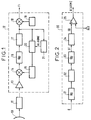
- FIG. 3 is a block diagram of another reception system comprising a presence or absence carrier detector.
- This reception system comprises, in addition to the elements already mentioned for the description of FIG. 1 and which bear the same numerical references, a frequency transposition stage composed by a mixer 40 controlled by a frequency synthesizer 41, for example intended to supply an IF signal at 450 MHz from a signal with a frequency approximately equal to 1 GHz.
- the comparison means 35 provide the ALARM signal indicative of the presence or absence of the carrier.
- FIG. 4 is a block diagram of a set of filters in parallel followed by a multiplexer, which can advantageously replace the filter 33 of FIG. 3, for the detection of symbol clock frequencies and the identification of the corresponding carriers.
- it is sought to identify one or more carriers, each carrier corresponding to a transmission channel and having its own symbol clock frequency, the symbol clock frequencies being different in the different channels.
- it may be a question of identifying which carrier is received from the corresponding symbolic bit rate.
- a set of three bandpass filters 42, 43, 44 is used here, the inputs of which are connected in parallel, the passbands of these filters being identical but centered on different frequencies.
- the outputs of the filters are applied to a multiplexer 45, the output of which is connected to the detection means 34.
- the multiplexer is controlled by a clock signal H. When a symbolic bit rate corresponding to that of a carrier is detected, the signal clock is inhibited (for example using the ALARM signal) and the symbolic rate information is supplied to the multi-rate demodulation means.
- FIG. 5 is a block diagram of a stage which can replace the stage of FIG. 4.
- a low-pass filter 50 suppresses the frequencies higher than that of the expected symbol clock frequency la more important.
- a frequency transposition stage constituted by a mixer 51 controlled by a local oscillator 52 receives this filtered signal.
- the oscillator 52 receives a frequency scanning signal BAL and the output signal from the mixer 51 is applied to a narrow band bandpass filter 53, for example identical to that referenced 33 in FIGS. 2 and 3.
- the oscillator local 52 provides an FS signal indicative of the current symbol clock frequency. When a symbol clock is detected, the BAL scan signal is inhibited.
- This embodiment can for example be used in a radio frequency scanner.
- the invention is of particular interest in receivers of TDMA or TDMA signals where an AGC is placed upstream. It allows to clearly distinguish the digital spectrum due to the modulation at the symbol frequency of the noise, for Eb / No ratios greater than or equal to 3 dB.
- the invention also relates to a method for detecting the presence or absence of a carrier wave of a signal received by a receiver, this carrier wave being modulated by a digital signal at the frequency of a symbol clock, this method of detecting the presence of the frequency of the symbol clock in the received signal to indicate the presence of the carrier wave.
Abstract
Description
Le domaine de l'invention est celui des télécommunications numériques, notamment par satellite, et concerne plus précisément un dispositif de détection de la présence ou de l'absence d'une onde porteuse d'un signal reçu par un récepteur, cette onde porteuse étant modulée par un signal numérique à la fréquence d'une horloge symbole. L'invention s'applique à tout type de modulation numérique, par exemple aux modulations par déplacement de phase (MDP-M, Modulation de phase à M états) ou aux modulations d'amplitude et de phase (MDAP-M, Modulation de phase et d'amplitude à M états) et à celles notamment utilisées dans les systèmes de télécommunications AMRT (Accès multiple à répartition dans le temps) ou AMRF (Accès multiple à répartition de fréquences).The field of the invention is that of digital telecommunications, in particular by satellite, and more specifically relates to a device for detecting the presence or absence of a carrier wave of a signal received by a receiver, this carrier wave being modulated by a digital signal at the frequency of a symbol clock. The invention applies to any type of digital modulation, for example to phase shift modulations (MDP-M, Phase modulation with M states) or to amplitude and phase modulations (MDAP-M, Phase modulation and of amplitude at M states) and to those used in particular in telecommunications systems TDMA (Time division multiple access) or AMRF (Frequency division multiple access).
Pour illustrer un exemple d'application de l'invention, on se placera dans la description suivante dans le cas d'un modem utilisé en réception dans un système de transmission par satellite.To illustrate an example of application of the invention, the following description will be used in the case of a modem used for reception in a satellite transmission system.
La figure 1 est un schéma synoptique d'un système de réception pour une transmission par satellite, le récepteur utilisé comprenant un détecteur de présence ou d'absence de porteuse.FIG. 1 is a block diagram of a reception system for a satellite transmission, the receiver used comprising a presence or absence carrier detector.
Le système de réception de la figure 1 comporte une antenne 10 recevant un signal hyperfréquence constitué par une porteuse en bande KU (12 GHz) modulée par un signal numérique, par exemple en MDP-4. Le signal capté par l'antenne 10 est appliqué à un LNB (Low Noise Block converter) 11 comprenant de manière classique un amplificateur faible bruit suivi par un dispositif de transposition en fréquence intermédiaire. Le signal de sortie du LNB 11 est par exemple en bande BIS (950 - 1750 MHz) et appliqué à un étage 12 de transposition de fréquence du modem.The reception system of FIG. 1 comprises an
L'étage 12 comporte un amplificateur 13 suivi par un mélangeur 14 recevant un signal de transposition d'un synthétiseur de fréquence 15. Le mélangeur 14 et le synthétiseur de fréquence 15 constituent un premier étage de transposition de fréquence. Le signal de sortie du mélangeur 14 a une fréquence fixe, comme il sera vu par la suite, et est appliqué à un filtre passe-bande 16 suivi par un dispositif 17 de commande automatique de gain (CAG). Le signal de sortie de la CAG 17 est appliqué à un second étage de transposition de fréquence constitué par un mélangeur 18 piloté par un oscillateur local 19. Le signal de sortie du mélangeur 18 est un signal Fl à 70 MHz. Ce signal est ensuite appliqué à l'étage de démodulation du récepteur qui a pour fonction de restituer les symboles MDP-4 transmis.
Le signal de sortie de la CAG 17 est également appliqué à un dispositif de commande automatique de fréquence 20 (CAF) pilotant le synthétiseur de fréquence 15, ainsi qu'à un dispositif 21 de détection de présence ou d'absence de porteuse. Le CAF 20 a pour fonction de compenser les éventuelles dérives de fréquence dues au dispositif de transposition de fréquence compris dans le LNB 11. Les dispositifs de transposition de fréquence habituellement employés dans les LNB comprennent un oscillateur local constitué par un résonateur. Un tel oscillateur peut présenter des dérives de fréquence importantes autour de sa fréquence centrale, d'où la nécessité d'employer un CAF en aval pour assurer qu'en sortie du mélangeur 14 la fréquence soit constante.The output signal from the
Le dispositif 21 de détection de présence ou d'absence de porteuse a pour fonction d'inhiber le fonctionnement du CAF 20 lorsqu'une absence de porteuse a été détectée, afin que le synthétiseur 15, qui est avantageusement large bande, ne s'accroche pas sur une fréquence intermédiaire correspondant à celle d'un canal adjacent. En effet, dans les transmissions par satellite, plusieurs porteuses sont utilisées simultanément au même débit symbole R et, selon la norme Intelsat IESS-308, deux canaux adjacents doivent pouvoir présenter des bandes se chevauchant partiellement (écart entre porteuses égal à 0,7R). De plus, un des canaux adjacents à celui reçu doit pouvoir présenter une amplitude allant jusqu'à 7 dB au-delà de celui reçu.The
Dans ces circonstances, si l'on ne prévoyait pas une inhibition du CAF 20 lorsque la porteuse disparaît, par exemple suite à un évanouissement sélectif temporaire, le CAF, qui est large bande, resynchroniserait le synthétiseur 15 sur un des canaux adjacents. Cette porteuse ne pourrait alors plus être récupérée ultérieurement et la liaison serait coupée. C'est pourquoi le dispositif 21 de détection de présence ou d'absence de porteuse génère un signal ALARME inhibant le fonctionnement du CAF 20 lorsqu'une absence de porteuse est détectée.Under these circumstances, if CAF 20 inhibition was not expected when the carrier disappears, for example as a result of temporary selective fading, the CAF, which is broadband, would resynchronize
De manière connue, la détection de la présence ou de l'absence d'une porteuse est réalisée par détection du niveau Fl (Fréquence Intermédiaire), c'est à dire que l'énergie du signal issu de la CAG 17 est comparée à une valeur de référence. Si cette valeur de référence est dépassée, la porteuse est considérée présente alors que si la valeur de référence n'est pas dépassée, la porteuse est considérée absente.In known manner, the detection of the presence or absence of a carrier is carried out by detection of the level F1 (Intermediate Frequency), that is to say that the energy of the signal coming from the
La détection de porteuse par détection FI pose cependant un problème lorsque la dynamique de la CAG 17 placée en amont est supérieure au rapport signal à bruit du signal reçu. En effet, en cas d'absence de porteuse, la CAG 17 amplifie le niveau de bruit au niveau de la porteuse absente et le signal ALARME n'est pas généré. Dans ce cas, le CAF 20 n'est pas inhibé et le synthétiseur 15 se calera sur la fréquence intermédiaire correspondant à celle d'un canal adjacent.Carrier detection by IF detection however poses a problem when the dynamics of the
De plus, même en l'absence de canaux adjacents, l'absence de détection de perte de porteuse peut avoir des incidences importantes sur le fonctionnement du récepteur. A titre d'exemple, dans une application de transmission AMRT, le récepteur reçoit des paquets d'informations espacés dans le temps. Afin de démoduler ces informations, il doit connaître l'enveloppe du signal reçu, c'est à dire les moments où débutent et se terminent les paquets. Dans l'état de la technique, cette information temporelle est obtenue de manière prédictive. L'inconvénient est que si l'émission des paquets cesse, par exemple suite à une panne de l'émetteur, la CAG amplifiera du bruit, le détecteur Fl de présence de porteuse ne fonctionnera pas et le CAF ne sera pas inhibé. En conséquence, le système AMRT se désynchronisera.In addition, even in the absence of adjacent channels, the absence of carrier loss detection can have significant effects on the operation of the receiver. For example, in a TDMA transmission application, the receiver receives time-spaced information packets. In order to demodulate this information, it must know the envelope of the received signal, that is to say the times when the packets start and end. In the state of the art, this temporal information is obtained in a predictive manner. The disadvantage is that if the transmission of packets stops, for example following a failure of the transmitter, the AGC will amplify noise, the detector F1 of presence of carrier will not work and the CAF will not be inhibited. As a result, the TDMA system will become out of sync.
La présente invention a notamment pour objectif de remédier à ces inconvénients.The present invention aims in particular to remedy these drawbacks.
Plus précisément, un des objectifs de l'invention est de fournir un dispositif fournissant une information fiable de présence ou d'absence d'une onde porteuse d'un signal reçu. Cette information ne doit notamment pas être tributaire d'une CAG placée en amont qui viendrait amplifier du bruit en l'absence de porteuse.More specifically, one of the objectives of the invention is to provide a device providing reliable information of the presence or absence of a carrier wave of a received signal. This information must in particular not be dependent on an AGC placed upstream which would amplify noise in the absence of carrier.
Cet objectif, ainsi que d'autres qui apparaîtront par la suite, est atteint grâce au fait que ce dispositif comporte :
- un circuit non linéaire recevant le signal reçu ou le signal reçu transposé en fréquence, ce circuit non linéaire fournissant notamment un signal dont la fréquence correspond à la fréquence de l'horloge symbole,
- un filtre bande étroite centré sur la fréquence de cette horloge symbole et fournissant un signal filtré,
- des moyens de détection du signal filtré fournissant un signal détecté,
- des moyens de comparaison du signal détecté avec une valeur de référence, le signal de sortie de ces moyens de comparaison constituant un signal indicateur de la présence ou de l'absence de l'onde porteuse.
- a nonlinear circuit receiving the received signal or the received signal transposed in frequency, this nonlinear circuit providing in particular a signal whose frequency corresponds to the frequency of the symbol clock,
- a narrow band filter centered on the frequency of this symbol clock and providing a filtered signal,
- means for detecting the filtered signal supplying a detected signal,
- means for comparing the detected signal with a reference value, the output signal from these comparison means constituting a signal indicating the presence or absence of the carrier wave.
Ainsi, la détection de la présence ou de l'absence de l'onde porteuse est obtenue grâce à la détection de la raie d'horloge générée par le circuit non-linéaire. La présence ou l'absence d'une porteuse modulée numériquement correspond respectivement à celle de la raie d'horloge.Thus, the detection of the presence or absence of the carrier wave is obtained thanks to the detection of the clock line generated by the non-linear circuit. The presence or absence of a digitally modulated carrier corresponds respectively to that of the clock line.
Le dispositif de l'invention comporte avantageusement un dispositif de transposition de fréquence placé entre le circuit non linéaire et le filtre bande étroite. Il est ainsi possible de détecter la présence ou l'absence de porteuses modulées par des signaux numériques à des fréquences symboles différentes.The device of the invention advantageously comprises a frequency transposition device placed between the non-linear circuit and the narrow band filter. It is thus possible to detect the presence or absence of carriers modulated by digital signals at different symbol frequencies.
Dans une application AMRF, le circuit non linéaire est préférentiellement précédé d'un filtre passe-bande assurant une troncature de canaux adjacents.In an AMRF application, the non-linear circuit is preferably preceded by a bandpass filter ensuring the truncation of adjacent channels.
Le dispositif de l'invention trouve un intérêt tout particulier lorsqu'il est compris dans un dispositif de transposition de fréquence comprenant un dispositif de commande automatique de gain placé en amont.The device of the invention is of particular interest when it is included in a frequency transposition device comprising an automatic gain control device placed upstream.
Dans une application préférentielle, le signal indicateur de la présence ou de l'absence de l'onde porteuse est appliqué à un dispositif de commande automatique de fréquence.In a preferred application, the signal indicating the presence or absence of the carrier wave is applied to an automatic frequency control device.
L'invention concerne également un récepteur de signaux multiplexés dans le temps comprenant un dispositif tel que décrit ci-dessus pour la délivrance d'un signal indicatif de la présence de paquets d'information.The invention also relates to a time-multiplexed signal receiver comprising a device as described above for delivering a signal indicative of the presence of information packets.
Par ailleurs, l'invention concerne un récepteur comprenant un tel dispositif prévu pour la détection de fréquences d'horloges symbole et l'identification des porteuses correspondantes. Il est ainsi possible d'identifier une porteuse, et donc un canal de transmission, à partir de la détection de la fréquence d'horloge symbole correspondant à ce canal.Furthermore, the invention relates to a receiver comprising such a device intended for the detection of symbol clock frequencies and the identification of the corresponding carriers. It is thus possible to identify a carrier, and therefore a transmission channel, from the detection of the symbol clock frequency corresponding to this channel.
L'invention concerne également un procédé de détection de la présence ou de l'absence d'une onde porteuse d'un signal reçu par un récepteur, l'onde porteuse étant modulée par un signal numérique à la fréquence d'une horloge symbole, ce procédé consistant à détecter la présence de la fréquence de l'horloge symbole dans le signal reçu pour indiquer la présence de l'onde porteuse.The invention also relates to a method for detecting the presence or absence of a carrier wave of a signal received by a receiver, the carrier wave being modulated by a digital signal at the frequency of a symbol clock, this method consisting in detecting the presence of the frequency of the symbol clock in the received signal to indicate the presence of the carrier wave.
D'autres caractéristiques et avantages de l'invention apparaîtront à la lecture de la description suivante d'un mode de réalisation préférentiel, donné à titre illustratif et non limitatif, et des dessins annexés dans lesquels :
- la figure 1 est un schéma synoptique d'un système de réception pour une transmission par satellite, le récepteur utilisé comprenant un détecteur de présence ou d'absence de porteuse ;
- la figure 2 est un schéma synoptique d'un dispositif de détection de la présence ou de l'absence d'une onde porteuse selon l'invention ;
- la figure 3 est un schéma synoptique d'un autre système de réception comprenant un détecteur de présence ou d'absence de porteuse ;
- la figure 4 est un schéma synoptique d'un jeu de filtres en parallèle suivis par un multiplexeur, pouvant avantageusement remplacer le filtre bande étroite 33 de la figure 3, pour la détection de fréquences d'horloges symbole et l'identification des porteuses correspondantes ;
- la figure 5 est un schéma synoptique d'un étage pouvant se substituer au jeu de filtres associés au multiplexeur de la figure 4.
- FIG. 1 is a block diagram of a reception system for a satellite transmission, the receiver used comprising a presence or absence carrier detector;
- Figure 2 is a block diagram of a device for detecting the presence or absence of a carrier wave according to the invention;
- FIG. 3 is a block diagram of another reception system comprising a presence or absence carrier detector;
- FIG. 4 is a block diagram of a set of filters in parallel followed by a multiplexer, which can advantageously replace the
narrow band filter 33 of FIG. 3, for the detection of symbol clock frequencies and the identification of the corresponding carriers; - FIG. 5 is a block diagram of a stage which can replace the set of filters associated with the multiplexer of FIG. 4.
La figure 1 a été décrite précédemment en référence à l'état de la technique.Figure 1 has been described above with reference to the state of the art.
Sur la figure 2, un dispositif de détection de la présence ou de l'absence d'une onde porteuse selon l'invention est généralement référencé par 30. Ce dispositif reçoit un signal d'entrée E et fournit un signal de sortie ALARME indicatif de la présence ou de l'absence d'une onde porteuse.In FIG. 2, a device for detecting the presence or absence of a carrier wave according to the invention is generally referenced by 30. This device receives an input signal E and provides an ALARM output signal indicative of the presence or absence of a carrier wave.
Le signal E peut être le signal reçu en hyperfréquence ou alors ce signal reçu transposé en fréquence. Il peut, dans ce dernier cas, indifféremment s'agir d'un signal en fréquence intermédiaire ou d'un signal en bande de base.The signal E can be the signal received at microwave frequency or else this received signal transposed into frequency. In the latter case, it may equally be an intermediate frequency signal or a baseband signal.
Lorsqu'il s'agit d'un signal en fréquence intermédiaire, le signal E est par exemple le signal issu de la CAG 17 de la figure 1. Dans ce cas, le dispositif 30 de la figure 2 remplace celui référencé 21 à la figure 1.When it is an intermediate frequency signal, the signal E is for example the signal coming from the
Le signal E est appliqué à l'entrée d'un filtre passe-bande 31, facultatif et représenté en traits discontinus, dont la fonction est de réaliser une troncature des canaux adjacents à celui considéré. Un tel filtre est notamment utilisé lorsque le signal reçu est de type AMRF. Le signal de sortie du filtre 31 est appliqué à l'entrée d'un circuit non linéaire 32, ce circuit non linéaire fournissant notamment un signal dont la fréquence correspond à la fréquence de l'horloge symbole ayant servi à moduler la porteuse au niveau émission.Signal E is applied to the input of an optional band-
Tout type de circuit non linéaire convient : on peut utiliser un amplificateur fonctionnant en saturation, un circuit d'élévation au carré,... De manière générale, toute non-linéarité produit dans le signal de sortie du circuit 32 un ensemble de raies (composantes fréquentielles) dont celle de l'horloge symbole utilisée au niveau émission. Tout spectre, que ce soit celui d'un signal hyperfréquence, en fréquence intermédiaire ou en bande de base, comporte cette raie d'horloge symbole, du moment que la porteuse est modulée par un signal numérique à cette fréquence symbole.Any type of non-linear circuit is suitable: one can use an amplifier operating in saturation, a square elevation circuit, ... In general, any non-linearity produces in the output signal of circuit 32 a set of lines ( frequency components) including that of the symbol clock used at transmission level. Any spectrum, whether that of a microwave signal, intermediate frequency or baseband, includes this clock line symbol, as long as the carrier is modulated by a digital signal at this symbol frequency.
Le signal de sortie du circuit 32 est appliqué à un filtre bande étroite 33 centré sur la fréquence de cette horloge symbole. On suppose que la fréquence de l'horloge symbole, c'est à dire de modulation, est connue. On obtient ainsi en sortie du filtre 33 un signal filtré SF correspondant à l'horloge symbole utilisée à l'émission. Ce signal filtré SF est appliqué à des moyens de détection 34, par exemple constitués par un détecteur à diode, fournissant un signal détecté SD. En présence d'une porteuse à l'entrée du récepteur, le signal détecté SD a un niveau important, alors qu'en l'absence de porteuse, ce signal détecté SD a un niveau faible. Le signal détecté SD est ensuite appliqué à des moyens de comparaison 35 de ce signal détecté SD avec une valeur de référence REF réglable prévue pour immuniser le système au bruit.The output signal from
Le signal de sortie des moyens de comparaison 35 constitue le signal ALARME indicateur de la présence ou de l'absence de l'onde porteuse.The output signal from the comparison means 35 constitutes the ALARM signal indicating the presence or absence of the carrier wave.
Le principal avantage de l'invention est que le gain du dispositif de l'invention est important puisque la largeur de bande du filtre 33 peut être très réduite par rapport à la bande de Nyquist du filtre utilisé à l'émission (spectre à 3 dB). De plus, la détection de la fréquence de l'horloge symbole n'est généralement pas perturbée par les conditions de propagation. La largeur de bande du filtre 33 peut par exemple être de l'ordre de 300 kHz pour tenir compte de la gigue et d'un éventuel Doppler, pour un débit symbolique de 30 Mbauds en MDP-4, soit pour une bande de Nyquist de 30 MHz. On obtient ainsi un gain de 20 dB sur le rapport signal à bruit.The main advantage of the invention is that the gain of the device of the invention is important since the bandwidth of the
Si le dispositif de l'invention doit être utilisé dans un récepteur recevant des signaux modulés à des fréquences symboles différentes, on placera un dispositif de transposition de fréquence entre le circuit non linéaire 32 et le filtre bande étroite 33, afin de toujours disposer du signal d'horloge symbole en amont de ce filtre. Il est également possible d'utiliser un filtre bande étroite agile en fréquence.If the device of the invention is to be used in a receiver receiving signals modulated at different symbol frequencies, a frequency transposition device will be placed between the
La figure 3 est un schéma synoptique d'un autre système de réception comprenant un détecteur de présence ou d'absence de porteuse.FIG. 3 is a block diagram of another reception system comprising a presence or absence carrier detector.
Ce système de réception comporte, outre les éléments déjà mentionnés pour la description de la figure 1 et qui portent les mêmes références numériques, un étage de transposition de fréquence composé par un mélangeur 40 piloté par un synthétiseur de fréquence 41, par exemple destiné à fournir un signal FI à 450 MHz à partir d'un signal de fréquence environ égale à 1 GHz. Les moyens de comparaison 35 fournissent le signal ALARME indicatif de la présence ou de l'absence de la porteuse.This reception system comprises, in addition to the elements already mentioned for the description of FIG. 1 and which bear the same numerical references, a frequency transposition stage composed by a
La figure 4 est un schéma synoptique d'un jeu de filtres en parallèle suivis par un multiplexeur, pouvant avantageusement remplacer le filtre 33 de la figure 3, pour la détection de fréquences d'horloges symbole et l'identification des porteuses correspondantes. Dans cette application, on cherche à identifier une ou plusieurs porteuses, chaque porteuse correspondant à un canal de transmission et ayant sa propre fréquence d'horloge symbole, les fréquences d'horloge symbole étant différentes dans les différents canaux. Il peut par exemple s'agir, dans une application civile, d'identifier quelle porteuse est reçue à partir du débit symbolique correspondant.FIG. 4 is a block diagram of a set of filters in parallel followed by a multiplexer, which can advantageously replace the
On utilise ici un jeu de trois filtres passe-bande 42, 43, 44 dont les entrées sont reliées en parallèle, les bandes passantes de ces filtres étant identiques mais centrées sur des fréquences différentes. Les sorties des filtres sont appliquées à un multiplexeur 45 dont la sortie est reliée aux moyens de détection 34. Le multiplexeur est commandé par un signal d'horloge H. Lorsqu'un débit symbolique correspondant à celui d'une porteuse est détecté, le signal d'horloge est inhibé (par exemple à l'aide du signal ALARME) et l'information de débit symbolique est fournie aux moyens de démodulation multi-débits.A set of three
La figure 5 est un schéma synoptique d'un étage pouvant se substituer à l'étage de la figure 4. Dans ce mode de réalisation, un filtre passe-bas 50 supprime les fréquences supérieures à celle de la fréquence d'horloge symbole attendue la plus importante. Un étage de transposition de fréquences constitué par un mélangeur 51 piloté par un oscillateur local 52 reçoit ce signal filtré. L'oscillateur 52 reçoit un signal BAL de balayage de fréquences et le signal de sortie du mélangeur 51 est appliqué à un filtre passe-bande à bande étroite 53, par exemple identique à celui référencé 33 dans les figures 2 et 3. L'oscillateur local 52 fournit un signal FS indicateur de la fréquence d'horloge symbole courante. Lorsqu'une horloge symbole est détectée, le signal de balayage BAL est inhibé. Ce mode de réalisation peut par exemple être utilisé dans un scanner radiofréquences.FIG. 5 is a block diagram of a stage which can replace the stage of FIG. 4. In this embodiment, a low-
L'invention trouve un intérêt tout particulier dans les récepteurs de signaux AMRT ou AMRF où une CAG est placée en amont. Elle permet de nettement distinguer le spectre numérique dû à la modulation à la fréquence symbole du bruit, pour des rapports Eb/No supérieurs ou égaux à 3 dB.The invention is of particular interest in receivers of TDMA or TDMA signals where an AGC is placed upstream. It allows to clearly distinguish the digital spectrum due to the modulation at the symbol frequency of the noise, for Eb / No ratios greater than or equal to 3 dB.
L'invention concerne également un procédé de détection de la présence ou de l'absence d'une onde porteuse d'un signal reçu par un récepteur, cette onde porteuse étant modulée par un signal numérique à la fréquence d'une horloge symbole, ce procédé consistant à détecter la présence de la fréquence de l'horloge symbole dans le signal reçu pour indiquer la présence de l'onde porteuse.The invention also relates to a method for detecting the presence or absence of a carrier wave of a signal received by a receiver, this carrier wave being modulated by a digital signal at the frequency of a symbol clock, this method of detecting the presence of the frequency of the symbol clock in the received signal to indicate the presence of the carrier wave.
Claims (9)
Applications Claiming Priority (2)
| Application Number | Priority Date | Filing Date | Title |
|---|---|---|---|
| FR9414528A FR2727813B1 (en) | 1994-12-02 | 1994-12-02 | DEVICE FOR DETECTING THE PRESENCE OR ABSENCE OF A DIGITALLY MODULATED CARRIER, CORRESPONDING RECEIVER AND METHOD |
| FR9414528 | 1994-12-02 |
Publications (2)
| Publication Number | Publication Date |
|---|---|
| EP0715434A1 true EP0715434A1 (en) | 1996-06-05 |
| EP0715434B1 EP0715434B1 (en) | 2002-08-28 |
Family
ID=9469432
Family Applications (1)
| Application Number | Title | Priority Date | Filing Date |
|---|---|---|---|
| EP95402661A Expired - Lifetime EP0715434B1 (en) | 1994-12-02 | 1995-11-27 | Detection device for presence of a digitally modulated carrier |
Country Status (6)
| Country | Link |
|---|---|
| US (1) | US6081559A (en) |
| EP (1) | EP0715434B1 (en) |
| CA (1) | CA2164070A1 (en) |
| DE (1) | DE69527920D1 (en) |
| FI (1) | FI955746A (en) |
| FR (1) | FR2727813B1 (en) |
Families Citing this family (7)
| Publication number | Priority date | Publication date | Assignee | Title |
|---|---|---|---|---|
| US6597668B1 (en) * | 1996-11-07 | 2003-07-22 | Harris Broadband Wireless Access, Inc. | System and method for maximizing efficiency in a time division duplex system employing dynamic asymmetry |
| US6452966B1 (en) * | 2000-01-19 | 2002-09-17 | Charles Industries, Ltd. | Digital signal carrier detector |
| JP3794622B2 (en) * | 2001-03-06 | 2006-07-05 | 独立行政法人情報通信研究機構 | Receiving device, receiving method, program, and information recording medium |
| JP4607391B2 (en) * | 2001-08-29 | 2011-01-05 | 株式会社日立国際電気 | Carrier wave extraction circuit |
| US6982644B2 (en) * | 2002-05-09 | 2006-01-03 | Hewlett-Packard Development Company, L.P. | Safety device |
| DE102005041503A1 (en) * | 2005-09-01 | 2007-04-05 | Atmel Germany Gmbh | Method and device for detecting the occupation of an adjacent channel with a signal |
| US20110038356A1 (en) * | 2009-08-13 | 2011-02-17 | Yuval Bachrach | VBR interference mitigation in an mmwave network |
Citations (2)
| Publication number | Priority date | Publication date | Assignee | Title |
|---|---|---|---|---|
| EP0089853A2 (en) * | 1982-03-23 | 1983-09-28 | Nec Corporation | Interference wave detection circuit for use in radio receiver |
| JPH1152811A (en) * | 1997-08-01 | 1999-02-26 | Ricoh Co Ltd | Toner recycling device |
Family Cites Families (9)
| Publication number | Priority date | Publication date | Assignee | Title |
|---|---|---|---|---|
| JPS4861063A (en) * | 1971-12-01 | 1973-08-27 | ||
| NL7810204A (en) * | 1978-10-10 | 1980-04-14 | Goudsmit Johan Herman | DENTAL CARE; BRUSH BODY SUITABLE FOR THIS. |
| CA1274003A (en) * | 1986-08-21 | 1990-09-11 | Susumu Otani | Carrier recovery circuitry immune to interburst frequency variations |
| NL8603110A (en) * | 1986-12-08 | 1988-07-01 | Philips Nv | SWITCH FOR RECOVERING A CARRIER. |
| CA1279906C (en) * | 1987-12-24 | 1991-02-05 | Hizuru Nawata | Carrier recovery circuit for offset qpsk demodulators |
| US5012492A (en) * | 1989-09-29 | 1991-04-30 | Ge Fanuc Automation North America, Inc. | Apparatus and method for detecting a carrier signal |
| EP0527249B1 (en) * | 1991-08-09 | 1997-12-17 | Nec Corporation | Carrier recovery apparatus for digital satellite communication system |
| JPH06244878A (en) * | 1993-02-18 | 1994-09-02 | Fujitsu Ltd | Modem |
| US5412687A (en) * | 1993-10-15 | 1995-05-02 | Proxim Incorporated | Digital communications equipment using differential quaternary frequency shift keying |
-
1994
- 1994-12-02 FR FR9414528A patent/FR2727813B1/en not_active Expired - Fee Related
-
1995
- 1995-11-27 EP EP95402661A patent/EP0715434B1/en not_active Expired - Lifetime
- 1995-11-27 DE DE69527920T patent/DE69527920D1/en not_active Expired - Lifetime
- 1995-11-29 FI FI955746A patent/FI955746A/en unknown
- 1995-11-29 CA CA002164070A patent/CA2164070A1/en not_active Abandoned
- 1995-11-30 US US08/565,045 patent/US6081559A/en not_active Expired - Fee Related
Patent Citations (2)
| Publication number | Priority date | Publication date | Assignee | Title |
|---|---|---|---|---|
| EP0089853A2 (en) * | 1982-03-23 | 1983-09-28 | Nec Corporation | Interference wave detection circuit for use in radio receiver |
| JPH1152811A (en) * | 1997-08-01 | 1999-02-26 | Ricoh Co Ltd | Toner recycling device |
Non-Patent Citations (1)
| Title |
|---|
| PATENT ABSTRACTS OF JAPAN vol. 13, no. 413 (E - 820) 12 September 1989 (1989-09-12) * |
Also Published As
| Publication number | Publication date |
|---|---|
| DE69527920D1 (en) | 2002-10-02 |
| FR2727813B1 (en) | 1997-01-10 |
| FI955746A (en) | 1996-06-03 |
| EP0715434B1 (en) | 2002-08-28 |
| FR2727813A1 (en) | 1996-06-07 |
| FI955746A0 (en) | 1995-11-29 |
| CA2164070A1 (en) | 1996-06-03 |
| US6081559A (en) | 2000-06-27 |
Similar Documents
| Publication | Publication Date | Title |
|---|---|---|
| EP0580216B1 (en) | System and receiver for orthogonal frequency division multiplexed signals provided with a frequency synchronisation circuit | |
| EP0559883B1 (en) | Device for digital transmission and direct conversion receiver | |
| EP0314101B1 (en) | Radiofrequency-optical transmission system, especially in the field of satellite communications | |
| EP0709980B1 (en) | Frequency synchronisation for OFDM system | |
| EP0480502B1 (en) | Cable network and modem apparatus for such a network | |
| FR2474791A1 (en) | DIVERSITY RADIO-TRANSMISSION SYSTEM OF SIMPLE AND ECONOMIC STRUCTURE, AND TELECOMMUNICATION NETWORK COMPRISING SUCH SYSTEMS | |
| CA2164433A1 (en) | Signaling for communication system whith modulated reference according to a time-base low | |
| EP0433198B1 (en) | Amplitude modulation transmission system with suppressed carrier maintaining the polarity of the transmitted signal | |
| EP2555016A1 (en) | Satellite payload for augmentation systems | |
| FR2626425A1 (en) | DISPERSE SPECTRUM COMMUNICATION APPARATUS | |
| EP0715434B1 (en) | Detection device for presence of a digitally modulated carrier | |
| WO1997021277A1 (en) | Method and device for reducing rf transmission interference and use thereof in an interactive television network | |
| EP0541406A1 (en) | Procedure and device for the transmission of two informations in a spread spectrum link | |
| EP0140753B1 (en) | Method and apparatus for the coherent demodulation of a digitally modulated carrier | |
| EP0013248A1 (en) | Hyperfrequency telecommunications apparatus | |
| CA2164435C (en) | Selection of a primary satellite | |
| EP0031746B1 (en) | Circuit for the demodulation of a signal modulated by digital information and receiver comprising such a circuit | |
| FR2688962A1 (en) | METHOD FOR THE TRANSMISSION OF BROADBAND DIGITAL SIGNALS FROM A STATION FIXED TO A MOBILE STATION. | |
| EP0790729A1 (en) | Correction of PLL phase noise in PSK and QAM receivers | |
| CA2060413C (en) | Interfering signal detection method and device for a digital data demodulator | |
| EP1894322B1 (en) | Satellite communications system having transmitting station diversity | |
| EP0876720B1 (en) | Transceiver terminals using a two-way rf signal with a single carrier frequency for both directions | |
| CA2062343A1 (en) | Controlled lock band frequency modulated signal receiver | |
| EP2146457A1 (en) | Method for temporal synchronisation of a digital signal, corresponding device and computer program product. | |
| FR2551937A1 (en) | FREQUENCY SLIDE RADIO RECEIVER |
Legal Events
| Date | Code | Title | Description |
|---|---|---|---|
| PUAI | Public reference made under article 153(3) epc to a published international application that has entered the european phase |
Free format text: ORIGINAL CODE: 0009012 |
|
| AK | Designated contracting states |
Kind code of ref document: A1 Designated state(s): BE DE ES GB IT NL SE |
|
| 17P | Request for examination filed |
Effective date: 19961112 |
|
| 17Q | First examination report despatched |
Effective date: 20010205 |
|
| GRAG | Despatch of communication of intention to grant |
Free format text: ORIGINAL CODE: EPIDOS AGRA |
|
| GRAG | Despatch of communication of intention to grant |
Free format text: ORIGINAL CODE: EPIDOS AGRA |
|
| GRAH | Despatch of communication of intention to grant a patent |
Free format text: ORIGINAL CODE: EPIDOS IGRA |
|
| GRAH | Despatch of communication of intention to grant a patent |
Free format text: ORIGINAL CODE: EPIDOS IGRA |
|
| GRAA | (expected) grant |
Free format text: ORIGINAL CODE: 0009210 |
|
| RAP1 | Party data changed (applicant data changed or rights of an application transferred) |
Owner name: ALCATEL |
|
| AK | Designated contracting states |
Kind code of ref document: B1 Designated state(s): BE DE ES GB IT NL SE |
|
| PG25 | Lapsed in a contracting state [announced via postgrant information from national office to epo] |
Ref country code: NL Free format text: LAPSE BECAUSE OF FAILURE TO SUBMIT A TRANSLATION OF THE DESCRIPTION OR TO PAY THE FEE WITHIN THE PRESCRIBED TIME-LIMIT Effective date: 20020828 Ref country code: IT Free format text: LAPSE BECAUSE OF FAILURE TO SUBMIT A TRANSLATION OF THE DESCRIPTION OR TO PAY THE FEE WITHIN THE PRE;WARNING: LAPSES OF ITALIAN PATENTS WITH EFFECTIVE DATE BEFORE 2007 MAY HAVE OCCURRED AT ANY TIME BEFORE 2007. THE CORRECT EFFECTIVE DATE MAY BE DIFFERENT FROM THE ONE RECORDED.SCRIBED TIME-LIMIT Effective date: 20020828 Ref country code: GB Free format text: LAPSE BECAUSE OF FAILURE TO SUBMIT A TRANSLATION OF THE DESCRIPTION OR TO PAY THE FEE WITHIN THE PRESCRIBED TIME-LIMIT Effective date: 20020828 |
|
| REG | Reference to a national code |
Ref country code: GB Ref legal event code: FG4D Free format text: NOT ENGLISH |
|
| REF | Corresponds to: |
Ref document number: 69527920 Country of ref document: DE Date of ref document: 20021002 |
|
| PG25 | Lapsed in a contracting state [announced via postgrant information from national office to epo] |
Ref country code: SE Free format text: LAPSE BECAUSE OF FAILURE TO SUBMIT A TRANSLATION OF THE DESCRIPTION OR TO PAY THE FEE WITHIN THE PRESCRIBED TIME-LIMIT Effective date: 20021128 |
|
| PG25 | Lapsed in a contracting state [announced via postgrant information from national office to epo] |
Ref country code: DE Free format text: LAPSE BECAUSE OF FAILURE TO SUBMIT A TRANSLATION OF THE DESCRIPTION OR TO PAY THE FEE WITHIN THE PRESCRIBED TIME-LIMIT Effective date: 20021129 |
|
| PG25 | Lapsed in a contracting state [announced via postgrant information from national office to epo] |
Ref country code: BE Free format text: LAPSE BECAUSE OF NON-PAYMENT OF DUE FEES Effective date: 20021130 |
|
| NLV1 | Nl: lapsed or annulled due to failure to fulfill the requirements of art. 29p and 29m of the patents act | ||
| GBV | Gb: ep patent (uk) treated as always having been void in accordance with gb section 77(7)/1977 [no translation filed] |
Effective date: 20020828 |
|
| PG25 | Lapsed in a contracting state [announced via postgrant information from national office to epo] |
Ref country code: ES Free format text: LAPSE BECAUSE OF FAILURE TO SUBMIT A TRANSLATION OF THE DESCRIPTION OR TO PAY THE FEE WITHIN THE PRESCRIBED TIME-LIMIT Effective date: 20030228 |
|
| BERE | Be: lapsed |
Owner name: *ALCATEL Effective date: 20021130 |
|
| PLBE | No opposition filed within time limit |
Free format text: ORIGINAL CODE: 0009261 |
|
| STAA | Information on the status of an ep patent application or granted ep patent |
Free format text: STATUS: NO OPPOSITION FILED WITHIN TIME LIMIT |
|
| 26N | No opposition filed |
Effective date: 20030530 |