EP0714835A1 - Device for mixing two components - Google Patents
Device for mixing two components Download PDFInfo
- Publication number
- EP0714835A1 EP0714835A1 EP95108564A EP95108564A EP0714835A1 EP 0714835 A1 EP0714835 A1 EP 0714835A1 EP 95108564 A EP95108564 A EP 95108564A EP 95108564 A EP95108564 A EP 95108564A EP 0714835 A1 EP0714835 A1 EP 0714835A1
- Authority
- EP
- European Patent Office
- Prior art keywords
- vessel
- depot
- recess
- film
- cutting
- Prior art date
- Legal status (The legal status is an assumption and is not a legal conclusion. Google has not performed a legal analysis and makes no representation as to the accuracy of the status listed.)
- Granted
Links
Images
Classifications
-
- B—PERFORMING OPERATIONS; TRANSPORTING
- B65—CONVEYING; PACKING; STORING; HANDLING THIN OR FILAMENTARY MATERIAL
- B65D—CONTAINERS FOR STORAGE OR TRANSPORT OF ARTICLES OR MATERIALS, e.g. BAGS, BARRELS, BOTTLES, BOXES, CANS, CARTONS, CRATES, DRUMS, JARS, TANKS, HOPPERS, FORWARDING CONTAINERS; ACCESSORIES, CLOSURES, OR FITTINGS THEREFOR; PACKAGING ELEMENTS; PACKAGES
- B65D81/00—Containers, packaging elements, or packages, for contents presenting particular transport or storage problems, or adapted to be used for non-packaging purposes after removal of contents
- B65D81/32—Containers, packaging elements, or packages, for contents presenting particular transport or storage problems, or adapted to be used for non-packaging purposes after removal of contents for packaging two or more different materials which must be maintained separate prior to use in admixture
- B65D81/3205—Separate rigid or semi-rigid containers joined to each other at their external surfaces
- B65D81/3211—Separate rigid or semi-rigid containers joined to each other at their external surfaces coaxially and provided with means facilitating admixture
-
- Y—GENERAL TAGGING OF NEW TECHNOLOGICAL DEVELOPMENTS; GENERAL TAGGING OF CROSS-SECTIONAL TECHNOLOGIES SPANNING OVER SEVERAL SECTIONS OF THE IPC; TECHNICAL SUBJECTS COVERED BY FORMER USPC CROSS-REFERENCE ART COLLECTIONS [XRACs] AND DIGESTS
- Y10—TECHNICAL SUBJECTS COVERED BY FORMER USPC
- Y10S—TECHNICAL SUBJECTS COVERED BY FORMER USPC CROSS-REFERENCE ART COLLECTIONS [XRACs] AND DIGESTS
- Y10S215/00—Bottles and jars
- Y10S215/08—Mixing
Definitions
- the invention relates to a device according to the preamble of claim 1.
- Devices for mixing two components consisting of a vessel with a connecting element and a lid element that can be placed on the vessel, are known in a wide variety of embodiments.
- attachments which are able to cut films inserted into the vessel by screwing a screw element on a threaded neck of a vessel.
- a cover element in the form of a cap is provided with a tooth protruding into the threaded neck of a container, which tooth cuts out a film in the threaded neck when the cap is screwed. If the film separates two different components, for example two liquids or a liquid and a powdery substance, a mixture of the two components results after the film has been cut through and the container shaken.
- DE-OS 42 19 063 discloses a device for mixing two components, consisting of an open-top vessel with a screw thread as a connecting element and a cover element that can be screwed onto the vessel, in which a cutting mandrel is provided in the region of the upper edge of the open vessel , and a detachable depot vessel is inserted into the screw element. With the cutting mandrel of the open container, a film of the depot container can be cut.
- Such devices can also be used for the separate storage of a dusting product and a liquid.
- a dusting product for example a natural hair dye powder
- a disadvantage of the known devices is that they are either relatively cumbersome to handle or are not suitable for at least partial reuse. Or they are not suitable for the use of relatively small, replaceable depot containers.
- the invention has for its object to provide a device for mixing two components, which does not have the disadvantages mentioned above.
- a recess is provided in the upper region of the cover element with at least one cutting mandrel at the edge of the recess, a detachable depot container with a film that can be cut open on the container side is inserted into the recess, and the lower one
- the inner diameter of the depot vessel is greater than twice the distance between the central axis of the depot vessel and the cutting mandrel.
- the depot vessel is placed in the recess of the lid element after the lid element has been screwed onto the vessel.
- the cutting mandrel arranged on the lid element pierces the film of the depot vessel.
- a product component contained in the depot vessel reaches the underlying vessel to a second product component present there.
- the entire device for mixing the product components is hermetically sealed. The mixing of the two product components can be improved by shaking the device.
- the device according to the invention is relatively simple in construction and therefore inexpensive to manufacture.
- the vessel and the screw element can be manufactured by injection molding, as can the depot vessel.
- the film for the depot vessel is connected to the depot vessel, for example, by heat sealing.
- the container and the lid element can be reused after cleaning using a new depot container.
- a restoration of the functionality of the device is easily possible by a user insofar as, instead of an empty depot vessel, only a new, filled depot vessel has to be inserted into the screw element.
- the diameter of the recess can also be relatively small, so that small depot vessels can also be used.
- the film is a plastic-coated aluminum film (claim 3)
- the two components are separated from a film which has very good barrier properties with regard to product diffusion due to the aluminum layer and which is based on its plastic coating (for example the same plastic as the depot container) the edge of the depot vessel can be sealed.
- a particularly simple handling of the device according to the invention is achieved if, according to claim 4, the depot vessel can be positively clamped into the cover element. An emptied depot vessel is pulled out of the lid element and a new depot vessel is inserted into the lid element.
- the depot vessel can be manufactured particularly precisely if it consists of injection-molded plastic.
- the plane in which the recess lies is inclined with respect to the bottom surface of the vessel, the dispensing behavior from the depot vessel into the vessel is improved.
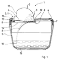
- the device 1 consists of an open vessel 2, a depot vessel 3 and a cover element 4 (FIG. 1).
- a cutting mandrel 6 is arranged on the upper region 5 of the cover element 4.
- the vessel 2 is provided with an external thread 7 at its upper region.
- the depot 3 is closed with a film 8.
- a mixture of the powder component 9 with the liquid component 10 in the vessel 2 results in a ready-to-use solution.
- the depot vessel 3 is inserted into the snap-in area 11.
- the film 8 of the depot vessel 3 snaps all around underneath the beveled locking ring 12 of the cover element 4.
- the depot vessel 3 is rotated while applying pressure with the aid of the gripping surface 13, and the cutting mandrel 6 circularly cuts through the film 8 and the powdery component 9 falls through the recess 14 of the cover element 4 into the liquid component 10.
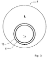
- the cutting mandrel 6 extends over more than a three-quarter circle around the recess 14 (FIG. 3).
- the device can be shaken for better mixing of the components.
- annular circumferential seal 15 (FIG. 1) in order to reliably prevent liquid leakage there.
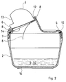
- the plane in which the recess 14 lies is inclined relative to the bottom surface 16 of the open vessel 2.
- the component 9 can be emptied better in the direction of the component 10 after the cutting process.
Landscapes
- Engineering & Computer Science (AREA)
- Mechanical Engineering (AREA)
- Details Of Rigid Or Semi-Rigid Containers (AREA)
- Closures For Containers (AREA)
Abstract
Description
Die Erfindung bezieht sich auf eine Vorrichtung gemäß dem Oberbegriff des Anspruchs 1.The invention relates to a device according to the preamble of
Vorrichtungen zum Mischen zweier Komponenten, bestehend aus einem Gefäß mit einem Verbindungselement und einem auf das Gefäß aufsetzbaren Deckelelement sind in den verschiedensten Ausführungsformen bekannt. Es gibt zum Beispiel Aufsätze, die über eine Schraubbewegung eines Schraubelementes auf einem Gewindehals eines Gefäßes in der Lage sind, in das Gefäß eingesetzte Folien durchzutrennen.Devices for mixing two components, consisting of a vessel with a connecting element and a lid element that can be placed on the vessel, are known in a wide variety of embodiments. There are, for example, attachments which are able to cut films inserted into the vessel by screwing a screw element on a threaded neck of a vessel.
Bei einer aus der DE-PS 39 24 152 bekannten Vorrichtung ist ein Deckelelement in Form einer Kappe mit einem in den Gewindehals eines Behälters hineinragenden Zahn versehen, der bei einer Schraubbewegung der Kappe eine Folie im Gewindehals herausschneidet. Trennt die Folie zwei verschiedene Komponenten, zum Beispiel zwei Flüssigkeiten oder eine Flüssigkeit und einen pulverförmigen Stoff, so ergibt sich nach der Durchtrennung der Folie und dem Schütteln des Behälters eine Mischung der beiden Komponenten.In a device known from DE-PS 39 24 152, a cover element in the form of a cap is provided with a tooth protruding into the threaded neck of a container, which tooth cuts out a film in the threaded neck when the cap is screwed. If the film separates two different components, for example two liquids or a liquid and a powdery substance, a mixture of the two components results after the film has been cut through and the container shaken.
Aus der DE-OS 42 19 063 ist eine Vorrichtung zum Mischen zweier Komponenten, bestehend aus einem oben offenem Gefäß mit einem Schraubgewinde als Verbindungselement und einem auf das Gefäß aufschraubbarem Deckelelement bekannt, bei der im Bereich des oberen Randes des offenen Gefäßes ein Schneiddorn vorgesehen ist, und in das Schraubelement ein lösbares Depotgefäß eingesetzt ist. Mit dem Schneiddorn des offenen Gefäßes kann eine Folie des Depotgefäßes durchtrennt werden.DE-OS 42 19 063 discloses a device for mixing two components, consisting of an open-top vessel with a screw thread as a connecting element and a cover element that can be screwed onto the vessel, in which a cutting mandrel is provided in the region of the upper edge of the open vessel , and a detachable depot vessel is inserted into the screw element. With the cutting mandrel of the open container, a film of the depot container can be cut.
Sinnvoll ist die Verwendung derartiger Vorrichtungen zum Beispiel zur getrennten Aufbewahrung von Flüssigkeitskomponenten, die erst kurz vor ihrem Gebrauch vermischt werden sollen. Eine Mischung aus den Einzelkomponenten ist dann nur über eine gewisse Zeitdauer verarbeitbar, so zum Beispiel die Komponenten Dauerwellösung und Ester für eine Haarbehandlung. Derartige Vorrichtungen können sinnvoll auch zur getrennten Aufbewahrung eines staubenden Produktes und einer Flüssigkeit verwendet werden. Infolge der Auflösung des staubenden Produktes, zum Beispiel eines natürlichen Haarfärbepulvers, in der Flüssigkeit ist eine Staubentwicklung zum Nachteil eines Anwenders zu keiner Zeit gegeben.It makes sense to use such devices, for example for the separate storage of liquid components which are to be mixed only shortly before they are used. A mixture of the individual components can then only be processed over a certain period of time, for example the components permanent wave solution and ester for a hair treatment. Such devices can also be used for the separate storage of a dusting product and a liquid. As a result of the dissolving of the dusting product, for example a natural hair dye powder, in the liquid there is no dust development to the disadvantage of a user at any time.
Nachteilig bei den bekannten Vorrichtungen ist, daß sie entweder relativ umständlich zu handhaben sind oder für eine zumindest teilweise Wiederbenutzung nicht geeignet sind. Oder sie sind für den Einsatz relativ kleiner, auswechselbarer Depotgefäße nicht geeignet.A disadvantage of the known devices is that they are either relatively cumbersome to handle or are not suitable for at least partial reuse. Or they are not suitable for the use of relatively small, replaceable depot containers.
Der Erfindung liegt die Aufgabe zugrunde, eine Vorrichtung zum Mischen zweier Komponenten zu schaffen, die oben genannte Nachteile nicht aufweist.The invention has for its object to provide a device for mixing two components, which does not have the disadvantages mentioned above.
Gelöst ist die Aufgabe gemäß dem kennzeichnenden Teil des Anspruchs 1. Nach Anspruch 1 ist im oberen Bereich des Deckelelementes eine Aussparung mit mindestens einem Schneiddorn am Rand der Aussparung vorgesehen, in die Aussparung ist ein lösbares Depotgefäß mit einer gefäßseitig aufschneidbaren Folie eingesetzt, und der untere Innendurchmesser des Depotgefäßes ist größer als der doppelte Abstand zwischen der Mittelachse des Depotgefäßes und dem Schneiddorn.The object is achieved according to the characterizing part of
Bei der erfindungsgemäßen Lösung wird das Depotgefäß in die Aussparung des Deckelelements gesetzt, nachdem das Deckelelement auf dem Gefäß festgeschraubt wurde.
Beim Aufsetzen des Depotgefäßes auf das Deckelelement durchsticht der auf dem Deckelelement angeordnete Schneiddorn die Folie des Depotgefäßes. Dadurch gelangt eine im Depotgefäß enthaltene Produktkomponente in das darunterliegende Gefäß zu einer dort vorhandenen zweiten Produktkomponente. Die gesamte Vorrichtung zum Mischen der Produktkomponenten ist hermetisch abgeschlossen. Die Durchmischung der beiden Produktkomponenten kann durch Schütteln der Vorrichtung verbessert werden.In the solution according to the invention, the depot vessel is placed in the recess of the lid element after the lid element has been screwed onto the vessel.
When the depot vessel is placed on the lid element, the cutting mandrel arranged on the lid element pierces the film of the depot vessel. As a result, a product component contained in the depot vessel reaches the underlying vessel to a second product component present there. The entire device for mixing the product components is hermetically sealed. The mixing of the two product components can be improved by shaking the device.
Die erfindungsgemäße Vorrichtung ist relativ einfach konstruiert und daher kostengünstig herstellbar. Das Gefäß und das Schraubelement können im Spritzgießverfahren hergestellt werden, das Depotgefäß ebenfalls. Die Folie für das Depotgefäß wird zum Beispiel durch Heißsiegelung mit dem Depotgefäß verbunden. Das Gefäß und das Deckelelement können nach ihrer Reinigung mittels eines neuen Depotgefäßes wiederverwendet werden. Die Wiederherstellung der Funktionstüchtigkeit der Vorrichtung ist durch einen Anwender insofern problemlos möglich, als anstatt eines geleerten Depotgefäßes lediglich ein neues, gefülltes Depotgefäß in das Schraubelement gesteckt werden muß.
Der Durchmesser der Aussparung kann auch relativ klein sein, so daß auch kleine Depotgefäße verwendet werden können.The device according to the invention is relatively simple in construction and therefore inexpensive to manufacture. The vessel and the screw element can be manufactured by injection molding, as can the depot vessel. The film for the depot vessel is connected to the depot vessel, for example, by heat sealing. The container and the lid element can be reused after cleaning using a new depot container. A restoration of the functionality of the device is easily possible by a user insofar as, instead of an empty depot vessel, only a new, filled depot vessel has to be inserted into the screw element.
The diameter of the recess can also be relatively small, so that small depot vessels can also be used.
Weitere vorteilhafte Ausgestaltungen der erfindungsgemäßen Vorrichtung sind in den Ansprüchen 2 bis 9 beschrieben.Further advantageous configurations of the device according to the invention are described in
Erstreckt sich der Schneiddorn um die Aussparung auf etwas mehr als einen Dreiviertelkreis (Anspruch 2), dann wird verhindert, daß die Folie vollständig vom Depotgefäß abgetrennt wird und in das darunterliegende Gefäß fällt, wo sich die beiden Produktkomponenten vermischen.If the cutting mandrel extends around the recess in a little more than a three-quarter circle (claim 2), then it is prevented that the film is completely separated from the depot vessel and falls into the vessel below, where the two product components mix.
Ist die Folie eine kunststoffbeschichtete Aluminiumfolie (Anspruch 3), so werden die beiden Komponenten von einer Folie getrennt, die auf Grund der Aluminiumschicht sehr gute Barriereeigenschaften bezüglich einer Produktdiffussion aufweist, und die auf Grund ihrer Kunststoffbeschichtung (zum Beispiel gleicher Kunststoff wie das Depotgefäß) auf den Rand des Depotgefäßes gesiegelt werden kann.If the film is a plastic-coated aluminum film (claim 3), the two components are separated from a film which has very good barrier properties with regard to product diffusion due to the aluminum layer and which is based on its plastic coating (for example the same plastic as the depot container) the edge of the depot vessel can be sealed.
Eine besonders einfache Handhabung der erfindungsgemäßen Vorrichtung ist erreicht, wenn gemäß Anspruch 4 das Depotgefäß formschlüssig in das Deckelelement einklemmbar ist. Ein entleertes Depotgefäß wird aus dem Deckelelement herausgezogen, und ein neues Depotgefäß wird in das Deckelelement hineingesteckt.A particularly simple handling of the device according to the invention is achieved if, according to
Ist am Rand des Gefäßes eine Dichtung vorgesehen (Anspruch 5), so wird beim Aufschrauben des Deckelelementes der Rand des Gefäßes gegen die Dichtung gedrückt und damit der Innenraum des Gefäßes hermetisch abgeschlossen. Auch beim Schütteln oder Drehen der zugeschraubten Vorrichtung kann keine Flüssigkeit aus der Vorrichtung austreten.If a seal is provided on the edge of the vessel (claim 5), the edge of the vessel is pressed against the seal when the cover element is screwed on, thus hermetically sealing the interior of the vessel. Even when the screwed-in device is shaken or rotated, no liquid can escape from the device.
Das Depotgefäß ist besonders passgenau herstellbar, wenn es gemäß Anspruch 6 aus spritzgegossenem Kunststoff besteht.The depot vessel can be manufactured particularly precisely if it consists of injection-molded plastic.
Sind am Depotgefäß Greifflächen vorgesehen (Anspruch 7), so sind das Aufstecken des Depotgefäßes auf das Deckelelement und ein Drehen des Depotgefäßes vereinfacht.If gripping surfaces are provided on the depot vessel (claim 7), the plugging of the depot vessel onto the cover element and turning of the depot vessel are simplified.
Ist analog Anspruch 8 die Ebene, in der die Aussparung liegt, gegenüber der Bodenfläche des Gefäßes geneigt, so ist das Ausschüttverhalten aus dem Depotgefäß in das Gefäß verbessert.If, analogously to claim 8, the plane in which the recess lies is inclined with respect to the bottom surface of the vessel, the dispensing behavior from the depot vessel into the vessel is improved.
Liegt die Schneidkante des Schneiddorns im Bereich des Einrastbereichs des Depotgefäßes (Anspruch 9), so ist es möglich, bereits beim Einrasten des Depotgefäßes dieses mittels der Schneidkante zu öffnen.If the cutting edge of the cutting mandrel lies in the area of the latching area of the depot vessel (claim 9), it is possible to open the depot vessel by means of the cutting edge when it snaps into place.
Im folgenden wird die Erfindung anhand von Ausführungsbeispiele darstellenden Figuren näher beschrieben. Es zeigt:
Figur 1- in einem Vertikalschnitt eine Vorrichtung, bestehend aus einem Gefäß mit einem Schraubgewinde, darauf aufgeschraubt ein Deckelelement mit einer Aussparung, einem Schneiddorn und einem Depotgefäß, welches auf den Schneiddorn oberhalb der Aussparung aufgesteckt ist;
Figur 2- in einem Vertikalschnitt eine Vorrichtung
analog Figur 1, jedoch mit einer Neigung der Aussparung gegenüber der Bodenfläche des Gefäßes, sowie - Figur 3
- in einer Draufsicht die Vorrichtung der
Figur 1, jedoch ohne Depotgefäß.
- Figure 1
- in a vertical section a device consisting of a vessel with a screw thread, screwed thereon a cover element with a recess, a cutting mandrel and a depot vessel which is attached to the cutting mandrel above the recess;
- Figure 2
- in a vertical section a device analogous to Figure 1, but with an inclination of the recess relative to the bottom surface of the vessel, and
- Figure 3
- in a plan view the device of Figure 1, but without a depot.
Die erfindungsgemäße Vorrichtung 1 besteht aus einem offenen Gefäß 2, einem Depotgefäß 3 und einem Deckelelement 4 (Figur 1). Am oberen Bereich 5 des Deckelelements 4 ist ein Schneiddorn 6 angeordnet. Das Gefäß 2 ist an dessen oberen Bereich mit einem Außengewinde 7 versehen. Das Depotgefäß 3 ist mit einer Folie 8 verschlossen. Im Depotgefäß 3 befindet sich eine pulverförmige Komponente 9. Eine Mischung der pulverförmigen Komponente 9 mit der flüssigen Komponente 10 im Gefäß 2 ergibt eine gebrauchsfertige Lösung.
Um die pulverförmige Komponente 9 in die flüssige Komponente 10 einzubringen, wird das Depotgefäß 3 in den Einrastbereich 11 gesteckt. Dabei verrastet die Folie 8 des Depotgefäßes 3 ringsum unterhalb des abgeschrägten Rastrings 12 des Deckelelementes 4. Dabei wird das Depotgefäß 3 unter Druckaufbringung unter Zuhilfenahme der Greiffläche 13 gedreht, und der Schneiddorn 6 durchschneidet kreisförmig die Folie 8 und die pulverförmige Komponente 9 fällt durch die Aussparung 14 des Deckelelementes 4 in die flüssige Komponente 10. Der Schneiddorn 6 erstreckt sich auf mehr als einen Dreiviertelkreis um die Aussparung 14 (Figur 3).The
In order to introduce the
Nachdem die pulverförmige Komponente 9 zu der flüssigen Komponente 10 gelangt ist, kann die Vorrichtung zwecks besserer Vermischung der Komponenten geschüttelt werden. Zwischen dem Deckelelement 4 und dem offenen Gefäß 2 befindet sich eine ringförmig umlaufende Dichtung 15 (Figur 1), um dort einen Flüssigkeitsaustritt sicher zu verhindern.After the
In einem anderen Ausführungsbeispiel (Figur 2) ist die Ebene, in der die Aussparung 14 liegt, gegenüber der Bodenfläche 16 des offenen Gefäßes 2 geneigt. Dadurch kann die Komponente 9 nach dem Schneidvorgang besser in Richtung der Komponente 10 ausgeleert werden.In another exemplary embodiment (FIG. 2), the plane in which the
Claims (9)
Applications Claiming Priority (2)
| Application Number | Priority Date | Filing Date | Title |
|---|---|---|---|
| DE4440264 | 1994-11-11 | ||
| DE4440264A DE4440264A1 (en) | 1994-11-11 | 1994-11-11 | Device for mixing two components |
Publications (2)
| Publication Number | Publication Date |
|---|---|
| EP0714835A1 true EP0714835A1 (en) | 1996-06-05 |
| EP0714835B1 EP0714835B1 (en) | 1998-07-29 |
Family
ID=6533032
Family Applications (1)
| Application Number | Title | Priority Date | Filing Date |
|---|---|---|---|
| EP95108564A Expired - Lifetime EP0714835B1 (en) | 1994-11-11 | 1995-06-03 | Device for mixing two components |
Country Status (3)
| Country | Link |
|---|---|
| US (1) | US5558215A (en) |
| EP (1) | EP0714835B1 (en) |
| DE (2) | DE4440264A1 (en) |
Families Citing this family (3)
| Publication number | Priority date | Publication date | Assignee | Title |
|---|---|---|---|---|
| EP1326780B1 (en) * | 2000-09-26 | 2005-04-20 | Ball Packaging Europe GmbH | Can top having a space for separately storing a small quantity of a substance |
| US20040099544A1 (en) * | 2002-01-22 | 2004-05-27 | Ness Richard B | Portable food container having separate compartments |
| WO2014189978A2 (en) | 2013-05-20 | 2014-11-27 | Principle Power, Inc. | System and method for controlling offshore floating wind turbine platforms |
Citations (6)
| Publication number | Priority date | Publication date | Assignee | Title |
|---|---|---|---|---|
| DE2432290A1 (en) * | 1974-07-05 | 1976-01-22 | Erich Wunsch | Plant spraying concentrate in closed capsule - is released into spraying tank from location sleeve in filler nozzle |
| US4201316A (en) * | 1975-04-25 | 1980-05-06 | Colgate-Palmolive Company | Capsule having frangible wall portion |
| EP0131132A2 (en) * | 1983-07-08 | 1985-01-16 | MIRA LANZA S.p.a. | Fitted up vessel for the prompt preparation of diluted detergents by starting from concentrated detergent single-dose containers |
| US4682689A (en) * | 1986-06-27 | 1987-07-28 | Clairol Incorporated | Dual compartment container |
| DE3924152C1 (en) | 1989-07-21 | 1990-12-13 | Wella Ag, 6100 Darmstadt, De | Plastic container designed for quick axial movement - consisting of threaded neck section with multiple thread and top section |
| DE4219063A1 (en) | 1992-06-11 | 1993-12-16 | Wella Ag | Device for mixing two components |
Family Cites Families (2)
| Publication number | Priority date | Publication date | Assignee | Title |
|---|---|---|---|---|
| ES247427Y (en) * | 1977-05-31 | 1981-06-16 | A PERFECTED CONTAINER WITH TWO COMPARTMENTS INTENDED TO CONTAIN PRODUCTS SEPARATED FROM EACH OTHER. | |
| IT212629Z2 (en) * | 1987-07-02 | 1989-07-23 | Gen Plastics Srl | HERMETICALLY CLOSED COMPOSITE CAP TO OBTAIN, EXTEMPORARY SOLUTION OF A POWDER IN A LIQUID SOLVENT WITH A CONTAINER |
-
1994
- 1994-11-11 DE DE4440264A patent/DE4440264A1/en not_active Withdrawn
-
1995
- 1995-06-03 DE DE59502976T patent/DE59502976D1/en not_active Expired - Fee Related
- 1995-06-03 EP EP95108564A patent/EP0714835B1/en not_active Expired - Lifetime
- 1995-11-01 US US08/551,650 patent/US5558215A/en not_active Expired - Fee Related
Patent Citations (6)
| Publication number | Priority date | Publication date | Assignee | Title |
|---|---|---|---|---|
| DE2432290A1 (en) * | 1974-07-05 | 1976-01-22 | Erich Wunsch | Plant spraying concentrate in closed capsule - is released into spraying tank from location sleeve in filler nozzle |
| US4201316A (en) * | 1975-04-25 | 1980-05-06 | Colgate-Palmolive Company | Capsule having frangible wall portion |
| EP0131132A2 (en) * | 1983-07-08 | 1985-01-16 | MIRA LANZA S.p.a. | Fitted up vessel for the prompt preparation of diluted detergents by starting from concentrated detergent single-dose containers |
| US4682689A (en) * | 1986-06-27 | 1987-07-28 | Clairol Incorporated | Dual compartment container |
| DE3924152C1 (en) | 1989-07-21 | 1990-12-13 | Wella Ag, 6100 Darmstadt, De | Plastic container designed for quick axial movement - consisting of threaded neck section with multiple thread and top section |
| DE4219063A1 (en) | 1992-06-11 | 1993-12-16 | Wella Ag | Device for mixing two components |
Also Published As
| Publication number | Publication date |
|---|---|
| EP0714835B1 (en) | 1998-07-29 |
| US5558215A (en) | 1996-09-24 |
| DE59502976D1 (en) | 1998-09-03 |
| DE4440264A1 (en) | 1996-05-15 |
Similar Documents
| Publication | Publication Date | Title |
|---|---|---|
| EP0573781B1 (en) | Device for mixing two components | |
| EP0775076B1 (en) | Closure cap and process for filling containers without forming gas bubbles | |
| EP0019794B1 (en) | Water purification apparatus | |
| DE19606163A1 (en) | Container for two substances | |
| EP0190593A2 (en) | Closure cap for two-component packaging systems | |
| DE2934711A1 (en) | RELOCKABLE LIQUID CONTAINER | |
| EP1009681A1 (en) | Dual-component container system | |
| EP0137458A2 (en) | Opening and discharging cap | |
| DE2934334A1 (en) | CONTAINER SHELL CAP | |
| DE7631891U1 (en) | Dispenser with application ball | |
| DE8416538U1 (en) | Combination container for two liquids | |
| EP0103600B1 (en) | Cap intended to be placed on the central outlet opening of a liquid container | |
| EP0714835B1 (en) | Device for mixing two components | |
| DE3208786A1 (en) | Two-chamber container with a destructible partition wall | |
| DE2705163C3 (en) | Disposable containers for sterile liquids | |
| WO2003057589A1 (en) | Closeable discharger for discharging a liquid, viscous or pasty medium contained in a container | |
| DE2940919A1 (en) | AIR-TIGHT SEALED, IN PARTICULAR PHARMACEUTICAL CONTAINER | |
| DE2602832A1 (en) | Dispensing capsule for liquid food prodn. - using pressurised fluid passed through lid to displace membrane and force food through funnel opening in bottom | |
| DE2709665A1 (en) | Bottle cap with adjustable opening - has ring of holes around round tapering stopper which fits inside bottle neck | |
| EP3575230A1 (en) | Drink bottle and stand for a drink bottle | |
| DE3140398A1 (en) | Applicator seal for containers for receiving liquid products | |
| EP0215202A1 (en) | Method for producing a synthetic closure cap for bottle-like containers | |
| DE3442344A1 (en) | Container closure with metal covering | |
| DE2233565C3 (en) | Hermetic closure system for thermos flasks and similar containers | |
| DE202018002710U1 (en) | Drinking bottle and stand for a drinking bottle |
Legal Events
| Date | Code | Title | Description |
|---|---|---|---|
| PUAI | Public reference made under article 153(3) epc to a published international application that has entered the european phase |
Free format text: ORIGINAL CODE: 0009012 |
|
| 17P | Request for examination filed |
Effective date: 19950603 |
|
| AK | Designated contracting states |
Kind code of ref document: A1 Designated state(s): DE FR GB IT |
|
| 17Q | First examination report despatched |
Effective date: 19970409 |
|
| GRAG | Despatch of communication of intention to grant |
Free format text: ORIGINAL CODE: EPIDOS AGRA |
|
| GRAG | Despatch of communication of intention to grant |
Free format text: ORIGINAL CODE: EPIDOS AGRA |
|
| GRAH | Despatch of communication of intention to grant a patent |
Free format text: ORIGINAL CODE: EPIDOS IGRA |
|
| GRAH | Despatch of communication of intention to grant a patent |
Free format text: ORIGINAL CODE: EPIDOS IGRA |
|
| GRAA | (expected) grant |
Free format text: ORIGINAL CODE: 0009210 |
|
| AK | Designated contracting states |
Kind code of ref document: B1 Designated state(s): DE FR GB IT |
|
| REF | Corresponds to: |
Ref document number: 59502976 Country of ref document: DE Date of ref document: 19980903 |
|
| GBT | Gb: translation of ep patent filed (gb section 77(6)(a)/1977) |
Effective date: 19981012 |
|
| ET | Fr: translation filed | ||
| PLBE | No opposition filed within time limit |
Free format text: ORIGINAL CODE: 0009261 |
|
| STAA | Information on the status of an ep patent application or granted ep patent |
Free format text: STATUS: NO OPPOSITION FILED WITHIN TIME LIMIT |
|
| 26N | No opposition filed | ||
| PGFP | Annual fee paid to national office [announced via postgrant information from national office to epo] |
Ref country code: GB Payment date: 20000512 Year of fee payment: 6 |
|
| PG25 | Lapsed in a contracting state [announced via postgrant information from national office to epo] |
Ref country code: GB Free format text: LAPSE BECAUSE OF NON-PAYMENT OF DUE FEES Effective date: 20010603 |
|
| GBPC | Gb: european patent ceased through non-payment of renewal fee |
Effective date: 20010603 |
|
| PG25 | Lapsed in a contracting state [announced via postgrant information from national office to epo] |
Ref country code: IT Free format text: LAPSE BECAUSE OF NON-PAYMENT OF DUE FEES;WARNING: LAPSES OF ITALIAN PATENTS WITH EFFECTIVE DATE BEFORE 2007 MAY HAVE OCCURRED AT ANY TIME BEFORE 2007. THE CORRECT EFFECTIVE DATE MAY BE DIFFERENT FROM THE ONE RECORDED. Effective date: 20050603 |
|
| PGFP | Annual fee paid to national office [announced via postgrant information from national office to epo] |
Ref country code: DE Payment date: 20080630 Year of fee payment: 14 |
|
| REG | Reference to a national code |
Ref country code: FR Ref legal event code: ST Effective date: 20100226 |
|
| PG25 | Lapsed in a contracting state [announced via postgrant information from national office to epo] |
Ref country code: FR Free format text: LAPSE BECAUSE OF NON-PAYMENT OF DUE FEES Effective date: 20090630 |
|
| PGFP | Annual fee paid to national office [announced via postgrant information from national office to epo] |
Ref country code: FR Payment date: 20080424 Year of fee payment: 14 |
|
| PG25 | Lapsed in a contracting state [announced via postgrant information from national office to epo] |
Ref country code: DE Free format text: LAPSE BECAUSE OF NON-PAYMENT OF DUE FEES Effective date: 20100101 |