EP0707936B1 - Process to determine the switch-over point in the production of an injection-moulded part - Google Patents
Process to determine the switch-over point in the production of an injection-moulded part Download PDFInfo
- Publication number
- EP0707936B1 EP0707936B1 EP95810562A EP95810562A EP0707936B1 EP 0707936 B1 EP0707936 B1 EP 0707936B1 EP 95810562 A EP95810562 A EP 95810562A EP 95810562 A EP95810562 A EP 95810562A EP 0707936 B1 EP0707936 B1 EP 0707936B1
- Authority
- EP
- European Patent Office
- Prior art keywords
- classification
- variables
- derived
- function
- evaluation
- Prior art date
- Legal status (The legal status is an assumption and is not a legal conclusion. Google has not performed a legal analysis and makes no representation as to the accuracy of the status listed.)
- Expired - Lifetime
Links
Images


Classifications
-
- B—PERFORMING OPERATIONS; TRANSPORTING
- B29—WORKING OF PLASTICS; WORKING OF SUBSTANCES IN A PLASTIC STATE IN GENERAL
- B29C—SHAPING OR JOINING OF PLASTICS; SHAPING OF MATERIAL IN A PLASTIC STATE, NOT OTHERWISE PROVIDED FOR; AFTER-TREATMENT OF THE SHAPED PRODUCTS, e.g. REPAIRING
- B29C45/00—Injection moulding, i.e. forcing the required volume of moulding material through a nozzle into a closed mould; Apparatus therefor
- B29C45/17—Component parts, details or accessories; Auxiliary operations
- B29C45/76—Measuring, controlling or regulating
- B29C45/77—Measuring, controlling or regulating of velocity or pressure of moulding material
- B29C2045/776—Measuring, controlling or regulating of velocity or pressure of moulding material determining the switchover point to the holding pressure
Definitions
- the invention relates to a method for determining a Switchover point in the manufacture of an injection molded part according to the preamble of claim 1.
- injection molded parts be it from Plastic, metal or ceramic materials each plastic in a cavity of an injection mold Material using a suitable injection device injected, which then solidified by cooling or is cured. The mold is then opened and the injection molded part ejected.
- the injection device according to a Filling program is usually controlled so that the Delivery rate as a function of time certain setpoint specifications Fulfills.
- the Injection device during a holding phase usually regulated so that according to a reprint program the pressure in the cavity reaches certain setpoints that can also be time-dependent.
- the switch point i.e. H. the point in time at which the filling program changes to the Reprint program is switched, is determined correctly and coincides as exactly as possible with the time at which the cavity is just completely filled. It gets too early switched, there is a risk that the cavity to at this point is not completely filled and a uncontrolled filling takes place under pressure, from which a susceptible to warping under thermal stress Injection molded part results. If the switchover is too late, so too high a pressure is reached in the cavity and it results an injection molded part that is brittle and prone to breakage due to internal stress is.
- JP-A-05096591 describes the use of fuzzy "logic" for the Control and regulation proposed an injection molding machine without that however an internal pressure measurement in the cavity of the injection mold carried out and an exact determination of the switchover point is carried out.
- the regulation of the screw speed of an injection molding machine to a predetermined setpoint depending on the Screw position is the content of EP-A-0.264.453, without that here the cavity pressure is measured, or the methods of Fuzzy logic can be applied.
- EP-A-0.525.670 relates to an arrangement and a method of Fuzzy logic, regardless of the area of application. On the special Problem of determining the switchover point during injection molding therefore not received.
- the invention is therefore based on the object, a generic Procedure to indicate that the complete filling of the Cavity safely and timely, but against Faults due to random pressure fluctuations in the filling phase is stable.
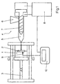
- the injection molding device of FIG. 1 has a shape 1 Metal, which encloses a cavity 2 in which the Injection molded part is molded.
- Form 1 is made from a z. B. hydraulic closing unit 3 closed and open.
- An injection device 4 is provided, which comprises an injection cylinder 5, on the upper side thereof a funnel 6 opens for the introduction of injection molding material and in which a screw 7 axially displaceable and is rotatably arranged. The movements of the screw 7 are determined by a controller 8.
- a pressure sensor 9 is arranged, which with a controller 10 is connected, which in turn with the Controller 8 is connected.
- the pressure sensor 9 could can also be arranged behind an ejector pin, in any case, it is located in cavity 2.
- the funnel 6 Injection molding compound usually in the form of granules, in the injection cylinder 5 introduced and by rapid rotation the screw 7 with simultaneous backward movement the same melted (Fig. 2a).
- the screw 7 In the cavity 2 of the mold 1 is no pressure in this first part of the filling phase built up (Fig. 2b).
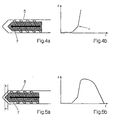
- the ideal Switchover point U is changed from on to the filling program Reprint program switched, in which the Pressure curve in cavity 2 according to certain specifications is regulated.
- the pressure from the Pressure sensor 9 (Fig. 1) monitors and the measurement result the controller 10 forwarded, which in turn in the sense of Compliance with a predetermined target pressure on the control 8 acts, which the axial position of the worm 7th controls that are usually still light at this stage is advanced (Fig. 5a).
- the target pressure can be a Function of time (Fig. 5b), which after steep Rise falls back to the original value because the Injection molding compound cools and contracts.
- the determination of the switchover point between the filling phase and the holding pressure phase is of crucial importance for the quality of the injection molded part.
- the pressure in the cavity 2 is monitored by the pressure sensor 9 already in the filling phase and at regular intervals, for. B. every 10 msec, a measured value is transmitted to the controller 10.
- the current measured value p 0 is processed together with the measured values p -1 or p -2 taken 10 or 20 msec ago. After 10 msec, a new current measured value p 0 is determined in each case, while the previous current measured value p 0 becomes the measured value p -1 and this becomes the measured value p -2 .
- the algorithmic processing of the measured values p 0 , p -1 and p -2 takes place (FIG. 6) in a computing unit in the controller 10 according to the fuzzy logic methods in several stages.
- classification levels K 0 , K -1 and K -2 two classification variables are derived from each of the measured values p 0 , p -1 and p -2 (fuzzyfication) by using first and second classification functions k 0 + , k 0 - , k -1 + , k -1 - or k -2 + , k -2 - can be applied to the measured values p 0 , p -1 or p -2 .
- the first classification function k 0 + has the value 0 up to a lower limit pressure of 345 bar and then increases linearly until it reaches the value 1 at 1202 bar.
- the second classification function is complementary to the first, ie it adds up to a constant, in the present case 1.
- the first classification function k -1 + for the measured value p -1 corresponds qualitatively to the already described classification function k 0 + for the current measured value p 0 , only it rises from 375 bar and reaches the value 1 at 1175 bar.
- the second classification function k - 1 - is again complementary to the first.
- the classification functions k -2 + and k -2 - for the measured value p -2 correspond exactly to those for the measured value p -1 in the present case.
- the classification variables resulting from the evaluation of the classification functions k 0 + (p 0 ), k 0 - (p 0 ), k -1 + (p -1 ), k -1 - (p -1 ), k -2 + ( p -2 ) and k -2 - (p -2 ) are linked in a linkage level V (inference) and weighting variables g - , g 0 and g + derived from them.
- intermediate sizes are first produced by forming minima over subsets of the quantity of the classification sizes. T.
- G - max [0.5 min (k 0 + , k -1 - , k -2 - ), 0.2 min (k 0 - , k -1 + , k -2 + ), 0.2 min (k 0 - , k -1 + , k -2 - )]
- G 0 max [0.5 min (k 0 + , k -1 + , k -2 - ), 0.5 min (k 0 + , k -1 - , k -2 - ), 0.2 min (k 0 - , k -1 + , k -2 - ), 0.6 min (k 0 - , k -1 - , k -2 + )]
- G + max [1.0 min (k 0 - , k -1 + ,
- each of the minima that lead to an intermediate variable is formed by a triple of classification variables, which is in each case composed of classification variables derived from the different measured values p 0 , p -1 and p -2 .
- classification variables k 0 + , k 0 - derived from the current measured value p 0 always occurs as an argument.
- a real switching value s in the present case between 0 and 1, is now derived from the weighting variables g - , g 0 and g + (defuzzification).
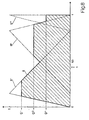
- the weighting variables g - , g 0 and g + are linked to fixed evaluation functions a - , a 0 and a + (FIG. 8).
- the graphs of the evaluation functions have surface centroids that are clearly offset from each other in the x direction, ie the median, corresponding to the x component of the surface centroid, is significantly larger at a + than at a ° and significantly larger at a ° than at a - .
- the carriers of the functions are also shifted accordingly, although they overlap widely.
- the evaluation functions are very simple in the present case. They all increase linearly from 0 to 1 and then also decrease linearly from 1 to 0.
- the linking of the weighting quantity g + with the evaluation function a + to a modified evaluation function takes place simply by cutting off the latter at the value of the weighting quantity g + , ie the minimum of the evaluation function a + and a constant function with the value g + is formed.
- the evaluation functions a 0 and a - are carried out analogously. From the evaluation functions modified in this way, a switching function a is finally formed by maximum formation, the graph of which consequently corresponds to the union of the graphs of the modified evaluation functions.
- the median is now used to determine the switching value s Switching function s according to the x component of your Center of gravity formed. It is obvious that every evaluation function the switching value all the more in the sense a shift against their own median, the larger the assigned weight size is.
- the switching value s is below a threshold value of 0.5, then is finally in a decision stage E (Fig. 6) derived that the switchover point has not yet been reached. If, on the other hand, the switching value exceeds the threshold, see above is derived from the fact that the switchover point is reached and switched to the reprint program.
Description
Die Erfindung betrifft ein Verfahren zur Bestimmung eines
Umschaltpunktes bei der Herstellung eines Spritzgussteils
gemäss dem Oberbegriff des Anspruchs 1.The invention relates to a method for determining a
Switchover point in the manufacture of an injection molded part
according to the preamble of
Bei der Herstellung von Spritzgussteilen, sei es aus Kunststoff, Metall oder keramischen Werkstoffen, wird jeweils in einen Hohlraum einer Spritzgussform plastisches Material mittels einer geeigneten Einspritzeinrichtung eingespritzt, das dann durch Kühlen verfestigt oder ausgehärtet wird. Anschliessend wird die Form geöffnet und das Spritzgussteil ausgeworfen. Beim Einspritzen folgen zwei Phasen aufeinander. Während einer Füllphase wird die Form gefüllt, wobei die Einspritzeinrichtung gemäss einem Füllprogramm gewöhnlich so gesteuert wird, dass die Förderrate als Funktion der Zeit bestimmte Sollwertvorgaben erfüllt. Sobald die Form voll ist, wird die Einspritzeinrichtung während einer Nachdruckphase gewöhnlich so geregelt, dass gemäss einem Nachdruckprogramm der Druck im Hohlraum bestimmte Sollwerte erreicht, die ebenfalls zeitabhängig sein können.In the manufacture of injection molded parts, be it from Plastic, metal or ceramic materials each plastic in a cavity of an injection mold Material using a suitable injection device injected, which then solidified by cooling or is cured. The mold is then opened and the injection molded part ejected. Follow when injecting two phases on each other. During a filling phase, the Mold filled, the injection device according to a Filling program is usually controlled so that the Delivery rate as a function of time certain setpoint specifications Fulfills. Once the form is full, the Injection device during a holding phase usually regulated so that according to a reprint program the pressure in the cavity reaches certain setpoints that can also be time-dependent.
Es ist von grosser Bedeutung, dass der Umschaltpunkt, d. h. der Zeitpunkt, zu dem vom Füllprogramm auf das Nachdruckprogramm umgeschaltet wird, richtig bestimmt wird und möglichst genau mit dem Zeitpunkt zusammenfällt, zu dem der Hohlraum gerade vollständig gefüllt ist. Wird zu früh umgeschaltet, so besteht die Gefahr, dass der Hohlraum zu diesem Zeitpunkt nicht vollständig gefüllt wird und ein unkontrolliertes Füllen unter Nachdruck erfolgt, woraus ein für Verzug unter thermischer Belastung anfälliges Spritzgussteil resultiert. Erfolgt die Umschaltung zu spät, so wird im Hohlraum ein zu hoher Druck erreicht und es resultiert ein Spritzgussteil, das wegen innerer Spannungen spröd und bruchgefährdet ist.It is very important that the switch point, i.e. H. the point in time at which the filling program changes to the Reprint program is switched, is determined correctly and coincides as exactly as possible with the time at which the cavity is just completely filled. It gets too early switched, there is a risk that the cavity to at this point is not completely filled and a uncontrolled filling takes place under pressure, from which a susceptible to warping under thermal stress Injection molded part results. If the switchover is too late, so too high a pressure is reached in the cavity and it results an injection molded part that is brittle and prone to breakage due to internal stress is.
Es ist also entscheidend, dass die vollständige Füllung des Hohlraums
erkannt wird, bevor es zu einem drastischen Druckanstieg
kommt. Bei einem bekannten Verfahren (DE-A-41 40 392) gemäss Oberbegriff
von Anspruch 1 wird versucht, dieses Problem zu lösen, indem
aus Messwerten, die bei in festen zeitlichen Abständen durchgeführten
Messungen des Drucks im Hohlraum gewonnen werden, die
zweite Ableitung des Drucks als Funktion der Zeit annähernd bestimmt
wird und, falls dieser Wert einen festen Schwellwert überschreitet,
auf Erreichen des Umschaltpunktes geschlossen und auf
das Nachdruckprogramm umgeschaltet wird.So it is critical that the cavity be completely filled
is detected before there is a drastic increase in pressure
is coming. In a known method (DE-A-41 40 392) according to the preamble
of
In der JP-A-05096591 wird die Anwendung der Fuzzy"Logik" für die Steuerung und Regelung eine Spritzgiessmaschine vorgeschlagen, ohne dass jedoch eine Innendruckmessung in der Kavität der Spritzgiessform durchgeführt und eine genaue Bestimmung des Umschaltpunktes durchgeführt wird.JP-A-05096591 describes the use of fuzzy "logic" for the Control and regulation proposed an injection molding machine without that however an internal pressure measurement in the cavity of the injection mold carried out and an exact determination of the switchover point is carried out.
In der nach dem Prioritäts- und dem Anmeldetag der vorliegenden Anmeldung veröffentlichten JP-A 07304079 wird eine Regelanordnung für die Einspritzgeschwindigkeit beschrieben, wobei der Umschaltpunkt mit Hilfe der unscharfen Logik ermittelt wird. Auch bei dieser Anordnung wird der Werkzeuginnendruck weder gemessen noch zur Regelung der Einspritzgeschwindigkeit herangezogen.In the after the priority and the filing date of the present Application published JP-A 07304079 is a control arrangement described for the injection speed, the switchover point is determined using the fuzzy logic. This one too The mold cavity pressure is neither measured nor Regulation of the injection speed used.
Die Regelung der Schneckengeschwindigkeit einer Spritzgiessmaschine auf einen vorgegebenen Sollwert in Abhängigkeit von der Schneckenposition ist Inhalt des EP-A-0.264.453, ohne dass auch hier der Werkzeuginnendruck gemessen wird, oder die Methoden der Fuzzy-Logik angewendet werden.The regulation of the screw speed of an injection molding machine to a predetermined setpoint depending on the Screw position is the content of EP-A-0.264.453, without that here the cavity pressure is measured, or the methods of Fuzzy logic can be applied.
Die EP-A-0.525.670 betrifft eine Anordnung und ein Verfahren der Fuzzy-Logik, unabhängig von dem Einsatzgebiet. Auf das spezielle Problem der Ermittlung des Umschaltpunktes beim Spritzgiessen wird daher nicht eingegangen. EP-A-0.525.670 relates to an arrangement and a method of Fuzzy logic, regardless of the area of application. On the special Problem of determining the switchover point during injection molding therefore not received.
Die Lösung nach der vorstehend diskutierten DE-A-4140392 hat sich für eine genaue Bestimmung des Umschaltpunktes als nicht genügend zuverlässig erwiesen, da auch vor der vollständigen Füllung des Hohlraums der Spritzgussform beträchtliche Schwankungen des Drucks auftreten können, die bewirken, dass die zweite Ableitung den Schwellwert kurzzeitig überschreitet, was eine verfrühte Umschaltung auslöst. Dem kann im Rahmen des bekannten Verfahrens nur durch einen hohen Schwellwert entgegengewirkt werden, was jedoch die Gefahr, dass die vollständige Füllung der Form zu spät erkannt wird und die Umschaltung nicht rechtzeitig erfolgt, erhöht.The solution according to DE-A-4140392 discussed above has not sufficient for an exact determination of the switchover point proven reliably because even before the complete filling of the Cavity of the injection mold considerable fluctuations in pressure can occur, which cause the second derivative the Threshold briefly exceeds what an early switchover triggers. This can only be done within the scope of the known method can be counteracted by a high threshold value, but what the risk that the full filling of the mold was recognized too late is increased and the switchover does not take place in time.
Der Erfindung liegt daher die Aufgabe zugrunde, ein gatttungsgemässes Verfahren anzugeben, das die vollständige Füllung des Hohlraums sicher und rechtzeitig feststellt, dabei aber gegen Störungen durch zufällig Druckschwankungen in der Füllphase stabil ist.The invention is therefore based on the object, a generic Procedure to indicate that the complete filling of the Cavity safely and timely, but against Faults due to random pressure fluctuations in the filling phase is stable.
Diese Aufgabe wird durch die Erfindung, wie sie im Anspruch 1
gekennzeichnet ist, gelöst.
Zweckmäßige Weiterbildungen der Erfindung sind
Gegenstand der abhängigen Ansprüche. Die Erfindung schafft ein Verfahren
zur Bestimmung des Umschaltpunktes, das sicher und zuverlässig
funktioniert und die Entstehung
fehlerhafter Spritzgussteile durch zu frühes oder zu spätes
Umschalten weitgehend ausschliesst.This object is achieved by the invention as set out in
Im folgenden wird die Erfindung anhand von Figuren, welche nur ein Ausführungsbeispiel darstellen, näher erläutert. Es zeigen
- Fig. 1
- eine Spritzgussvorrichtung zur Herstellung eines Spritzgussteils, welche zur Durchführung des erfindungsgemässen Verfahrens geeignet ist,
- Fig. 2a,b
- eine Einspritzeinrichtung bzw. den Druck im Hohlraum als Funktion der Zeit während eines ersten Teils der Füllphase,
- Fig. 3a,b
- Darstellungen entsprechend Fig. 2a,b während bzw. einschliesslich eines zweiten Teils der Füllphase,
- Fig. 4a,b
- Darstellungen entsprechend Fig. 2a,b beim Erreichen des Umschaltpunkts bzw. einschliesslich einer Umgebung des Umschaltpunkts,
- Fig. 5a,b
- Darstellungen entsprechend Fig. 2a,b während bzw. einschliesslich der Nachdruckphase,
- Fig. 6
- diagrammatisch die algorithmische Verarbeitung von Messwerten beim erfindungsgemässen Verfahren,
- Fig. 7a,b
- Klassifikationsfunktionen für den aktuellen Messwert bzw. die zwei letzten vor demselben erhobenen Messwerte und
- Fig. 8
- Auswertungsfunktionen für die Bestimmung eines Schaltwertes.
- Fig. 1
- an injection molding device for producing an injection molded part which is suitable for carrying out the method according to the invention,
- 2a, b
- an injection device or the pressure in the cavity as a function of time during a first part of the filling phase,
- 3a, b
- 2a, b during or including a second part of the filling phase,
- 4a, b
- 2a, b when the switchover point is reached or including an environment of the switchover point,
- 5a, b
- 2a, b during or including the holding pressure phase,
- Fig. 6
- diagrammatically the algorithmic processing of measured values in the method according to the invention,
- 7a, b
- Classification functions for the current measured value or the two last measured values and before
- Fig. 8
- Evaluation functions for determining a switching value.
Die Spritzgussvorrichtung von Fig. 1 weist eine Form 1 aus
Metall auf, welche einen Hohlraum 2 umschliesst, in dem das
Spritzgussteil geformt wird. Die Form 1 wird von einer z.
B. hydraulischen Schliesseinheit 3 geschlossen und
geöffnet. Zur Vorbereitung und zum Einspritzen von
Spritzgussmasse ist eine Einspritzeinrichtung 4 vorgesehen,
welche einen Spritzzylinder 5 umfasst, an dessen Oberseite
ein Trichter 6 zur Einführung von Spritzgussmaterial mündet
und in welchem eine Schnecke 7 axial verschiebbar und
drehbar angeordnet ist. Die Bewegungen der Schnecke 7
werden von einer Steuerung 8 bestimmt. In der Wand des
Hohlraums 2 ist ein Drucksensor 9 angeordnet, welcher mit
einem Regler 10 verbunden ist, der seinerseits mit der
Steuerung 8 in Verbindung steht. Der Drucksensor 9 könnte
auch hinter einem Auswerferstift angeordnet sein,
jedenfalls befindet er sich im Hohlraum 2.The injection molding device of FIG. 1 has a
Zu Beginn eines Spritzgiesszyklus wird durch den Trichter 6
Spritzgussmasse, üblicherweise in Form eines Granulats, in
den Spritzzylinder 5 eingebracht und durch rasche Drehung
der Schnecke 7 bei gleichzeitiger Rückwärtsbewegung
derselben aufgeschmolzen (Fig. 2a). Im Hohlraum 2 der Form
1 wird in diesem ersten Teil der Füllphase noch kein Druck
aufgebaut (Fig. 2b).At the beginning of an injection molding cycle, the
Zu Beginn des anschliessenden zweiten Teils der Füllphase
ist die Spitze der Schnecke 7 von der Spitze des
Spritzzylinders 5 beabstandet, der vordere Bereich
desselben ist mit aufgeschmolzener Spritzgussmasse gefüllt
(Fig. 3a). Im Verlauf des besagten zweiten Teils wird die
Schnecke 7 nach vorne geschoben und der Hohlraum 2 mit
Spritzgussmasse aufgefüllt. Die Vorwärtsbewegung wird nach
einem Füllprogramm gesteuert, das die Förderrate als
Funktion der Zeit vorgibt. Der Druck im Hohlraum 2 steigt
an (Fig. 3b).At the beginning of the second part of the filling phase
is the tip of the
Sobald der Hohlraum 2 vollständig gefüllt ist, endet die
Füllphase und beginnt die Nachdruckphase. Die Steigung des
Drucks als Funktion der Zeit steigt sprunghaft an (Fig. 4a,
4b).As soon as the
Möglichst genau zu diesem Zeitpunkt, d. h. am idealen
Umschaltpunkt U, wird vom Füllprogramm auf ein
Nachdruckprogramm umgeschaltet, bei welchem der
Druckverlauf im Hohlraum 2 nach bestimmten Vorgaben
geregelt wird. Zu diesem Zweck wird der Druck durch den
Drucksensor 9 (Fig. 1) überwacht und das Messergebnis an
den Regler 10 weitergeleitet, der seinerseits im Sinne der
Einhaltung eines vorgegebenen Solldrucks auf die Steuerung
8 einwirkt, welche die axiale Position der Schnecke 7
steuert, die in diesem Stadium gewöhnlich noch leicht
vorgeschoben wird (Fig. 5a). Der Solldruck kann eine
Funktion der Zeit sein (Fig. 5b), welche nach steilem
Anstieg wieder auf den Ursprungswert absinkt, da sich die
Spritzgussmasse abkühlt und zusammenzieht.As precisely as possible at this point in time. H. the ideal
Switchover point U is changed from on to the filling program
Reprint program switched, in which the
Pressure curve in
Wie bereits ausgeführt, ist die Bestimmung des
Umschaltpunktes zwischen der Füllphase und der
Nachdruckphase von entscheidender Bedeutung für die
Qualität des Spritzgussteils. Zum Zweck dieser Bestimmung
wird bereits in der Füllphase der Druck im Hohlraum 2 durch
den Drucksensor 9 überwacht und in regelmässigen Abständen,
z. B. alle 10 msec, ein Messwert an den Regler 10
übermittelt. Nach einer Messung wird der aktuelle Messwert
p0 zusammen mit den vor 10 bzw. 20 msec abgenommenen
Messwerten p-1 bzw. p-2 zusammen verarbeitet. Nach 10 msec
wird jeweils ein neuer aktueller Messwert p0 bestimmt,
während der bisherige aktuelle Messwert p0 zum Messwert p-1
und dieser zum Messwert p-2 wird.As already stated, the determination of the switchover point between the filling phase and the holding pressure phase is of crucial importance for the quality of the injection molded part. For the purpose of this determination, the pressure in the
Die algorithmische Verarbeitung der Messwerte p0, p-1 und p-2
erfolgt (Fig. 6) in einer Recheneinheit im Regler 10 nach
den Methoden der unscharfen Logik (fuzzy logic) in mehreren
Stufen. Zuerst werden in Klassifizierungsstufen K0, K-1 und
K-2 aus jedem der Messwerte p0, p-1 und p-2 jeweils zwei
Klassifizierungsgrössen abgeleitet (fuzzyfication), indem
erste und zweite Klassifizierungsfunktionen k0 +, k0 -,
k-1 +, k-1 - bzw. k-2 +, k-2 - jeweils auf die Messwerte p0, p-1
bzw. p-2 angewandt werden. Die erste
Klassifizierungsfunktion k0 + hat bis zu einem unteren
Grenzdruck von 345 bar den Wert 0 und steigt dann linear
an, bis sie bei 1202 bar den Wert 1 erreicht. Die zweite
Klassifizierungsfunktion ist zur ersten komplementär, d. h.
sie addiert sich mit derselben zu einer Konstanten, im
vorliegenden Fall 1.The algorithmic processing of the measured values p 0 , p -1 and p -2 takes place (FIG. 6) in a computing unit in the
Die erste Klassifizierungsfunktion k-1 + für den Messwert p-1
entspricht qualitativ der bereits beschriebenen
Klassifizierungsfunktion k0 + für den aktuellen Messwert p0,
nur steigt sie ab 375 bar an und erreicht bei 1175 bar den
Wert 1. Die zweite Klassifizierungsfunktion k-1 - ist
wiederum zur ersten komplementär. Die
Klassifizierungsfunktionen k-2 + und k-2 - für den Messwert p-2
entsprechen im vorliegend beschriebenen Fall genau denen
für den Messwert p-1.The first classification function k -1 + for the measured value p -1 corresponds qualitatively to the already described classification function k 0 + for the current measured value p 0 , only it rises from 375 bar and reaches the
Die sich aus der Auswertung der Klassifizierungsfunktionen
ergebenden Klassifizierungsgrössen k0 +(p0), k0 -(p0),
k-1 +(p-1), k-1 -(p-1), k-2 +(p-2) und k-2 -(p-2) (die Argumente p0,
p-1 und p-2 werden im folgenden weggelassen) werden in einer
Verknüpfungsstufe V verknüpft (inference) und
Gewichtungsgrössen g-, g0 und g+ aus ihnen abgeleitet. Dazu
werden jeweils zuerst durch Bildung von Minima über
Teilmengen der Menge der Klassifizierungsgrössen
Zwischengrössen hergestellt, dieselben z. T. skaliert, d.
h. mit festen Faktoren, im vorliegenden Fall ≤1,
multipliziert und dann jeweils durch Bildung von Maxima
über Zwischengrössen die Gewichtungsgrössen hergestellt. Im
einzelnen:
Offensichtlich wird jedes der Minima, die zu einer Zwischengrösse führen, über ein Tripel von Klassifizierungsgrössen gebildet, welches jeweils aus von den verschiedenen Messwerten p0, p-1 bzw. p-2 abgeleiteten Klassifizierungsgrössen zusammengesetzt ist. Insbesondere tritt immer eine der beiden vom aktuellen Messwert p0 abgeleiteten Klassifizierungsgrössen k0 +, k0 - als Argument auf.Obviously, each of the minima that lead to an intermediate variable is formed by a triple of classification variables, which is in each case composed of classification variables derived from the different measured values p 0 , p -1 and p -2 . In particular, one of the two classification variables k 0 + , k 0 - derived from the current measured value p 0 always occurs as an argument.
In einer Auswertungsstufe A wird nun aus den Gewichtungsgrössen g-, g0 und g+ ein reeller, im vorliegenden Fall zwischen 0 und 1 liegender Schaltwert s abgeleitet (defuzzification). Dazu werden die Gewichtungsgrössen g-, g0 und g+ mit festen Auswertungsfunktionen a-, a0 bzw. a+ (Fig. 8) verknüpft. Die Graphen der Auswertungsfunktionen haben in x-Richtung deutlich gegeneinander versetzte Flächenschwerpunkte, d. h. der Median, entsprechend der x-Komponente des Flächenschwerpunkts, ist bei a+ deutlich grösser als bei a° und bei a° wesentlich grösser als bei a-. Die Träger der Funktionen sind ebenfalls entsprechend verschoben, obwohl sie breit überlappen. Die Auswertungsfunktionen sind im vorliegenden Fall sehr einfach. Sie steigen durchwegs linear von 0 auf 1 und fallen dann ebenfalls linear von 1 auf 0 ab.In an evaluation stage A, a real switching value s, in the present case between 0 and 1, is now derived from the weighting variables g - , g 0 and g + (defuzzification). For this purpose, the weighting variables g - , g 0 and g + are linked to fixed evaluation functions a - , a 0 and a + (FIG. 8). The graphs of the evaluation functions have surface centroids that are clearly offset from each other in the x direction, ie the median, corresponding to the x component of the surface centroid, is significantly larger at a + than at a ° and significantly larger at a ° than at a - . The carriers of the functions are also shifted accordingly, although they overlap widely. The evaluation functions are very simple in the present case. They all increase linearly from 0 to 1 and then also decrease linearly from 1 to 0.
Die Verknüpfung der Gewichtungsgrösse g+ mit der Auswertungsfunktion a+ zu einer modifizierten Auswertungsfunktion erfolgt einfach durch Abschneiden der letzteren beim Wert der Gewichtungsgrösse g+, d. h. es wird das Minimum der Auswertungsfunktion a+ und einer konstanten Funktion mit dem Wert g+ gebildet. Bei den Auswertungsfunktionen a0 und a- wird analog vorgegangen. Aus den so modifizierten Auswertungsfunktionen wird schliesslich durch Maximumbildung eine Schaltfunktion a gebildet, deren Graph folglich die Vereinigungsmenge der Graphen der modifizierten Auswertungsfunktionen entspricht.The linking of the weighting quantity g + with the evaluation function a + to a modified evaluation function takes place simply by cutting off the latter at the value of the weighting quantity g + , ie the minimum of the evaluation function a + and a constant function with the value g + is formed. The evaluation functions a 0 and a - are carried out analogously. From the evaluation functions modified in this way, a switching function a is finally formed by maximum formation, the graph of which consequently corresponds to the union of the graphs of the modified evaluation functions.
Zur Bestimmung des Schaltwerts s wird nun der Median der Schaltfunktion s entsprechend der x-Komponente ihres Flächenschwerpunkts gebildet. Es ist offensichtlich, dass jede Auswertungsfunktion den Schaltwert umso mehr im Sinne einer Verschiebung gegen ihren eigenen Median beeinflusst, je grösser die zugeordnete Gewichtungsgrösse ist.The median is now used to determine the switching value s Switching function s according to the x component of your Center of gravity formed. It is obvious that every evaluation function the switching value all the more in the sense a shift against their own median, the larger the assigned weight size is.
Liegt der Schaltwert s unter einem Schwellwert von 0,5, so wird schliesslich in einer Entscheidungsstufe E (Fig. 6) abgeleitet, dass der Umschaltpunkt noch nicht erreicht ist. Ueberschreitet der Schaltwert dagegen den Schwellwert, so wird daraus abgeleitet, dass der Umschaltpunkt erreicht und auf das Nachdruckprogramm umgeschaltet ist.If the switching value s is below a threshold value of 0.5, then is finally in a decision stage E (Fig. 6) derived that the switchover point has not yet been reached. If, on the other hand, the switching value exceeds the threshold, see above is derived from the fact that the switchover point is reached and switched to the reprint program.
Mit Klassifizierungsfunktionen, Verknüpfungsregeln und Auswertungsfunktionen und -methoden wie oben angegeben wurden auf einem breiten Anwendungsgebiet sehr gute Resultate erzielt. Es sind jedoch auch weitgehende Abweichungen von dem geschilderten Beispiel möglich. Insbesondere kann weitere Optimierung und Anpassung an spezifische Anwendungen zu einer in Einzelheiten abweichenden algorithmischen Verarbeitung der Messwerte führen. Es ist auch möglich, eine andere Zahl oder Auswahl von Messwerten in die Verarbeitung einzubeziehen.With classification functions, linking rules and Evaluation functions and methods as stated above have been very good in a wide range of applications Results achieved. However, they are also extensive Deviations from the example described possible. In particular, further optimization and adaptation to specific applications to one in detail deviating algorithmic processing of the measured values to lead. It is also possible to choose another number or selection of measured values in the processing.
Claims (20)
- A method for determining the changeover point (U) when
producing plastic injection mouldings or die castings, where an injection device (4) serves to fill a cavity (2) in a mould (1) up to the changeover point (U) according to a filling program, then after the changeover point (U) a pressure curve is set up in the cavity according to a hold pressure program, by performing several successive measurements of the pressure inside the cavity (2) and after each measurement deciding by algorithmic processing of the current measured value (p0) and of previous measured values (p-1, p-2) in a computer whether the changeover point (U) has been reached or not, characterized by the algorithmic processing of the measured values (p0, p-1, p-2) being accomplished by functional combination of classification variables (k0+(p0), k0-(p0), k-1 +(p-1), k-1-(p-1), k-2+(p-2), k-2-(p-2) derived in a classification stage (K0, K-1, K-2) from these, using the methods of fuzzy logic. - Method according to claim 1, characterized by a first classification variable (k0+(p0); k-1+(p-1); k-2+(p-2) being derived from a measured value (p0; p-1; p-2), in which evaluation is accomplished in a first classification function (k0+; k-1+; k-2+).
- Method according to claim 2, characterized by the first classification function (k0+; k-1+; k-2+) having a constant value at low pressures and rising within an interval beginning with a positive lower limit pressure.
- Method according to claim 1 or 2, characterized by a second classification variable (k0-(p0); k-1-(p-1); k-2-(p-2) being derived from a measured value (p0; p-1; p-2), by evaluating it in a second classification function (ko-; k-1-); k-2-)
- Method according to claims 3 and 4, characterized by the second classification function (ko-; k-1-); k-2-) being complementary to the first one (k0+; k-1+; k-2+).
- Method according to one of claims 3 to 5, characterized by the lower limit pressure lying between 300 bar and 450 bar.
- Method according to one of claims 3 to 6, characterized by the lower limit pressure used when evaluating the current measured value (p0 with the first classification function (k0+) being lower than for the other first classification functions (k-1+, k-2+).
- Method according to one of claims 2 to 7, characterized by at least two weighting variables (g-, g0, g+) being derived from the classification variables (k0+(p0), k0-(p0), k-1+(p-1), k-1-(p-1), k-2+(p-2), k-2-(p-2) in a combination stage (V).
- Method according to claim 8, characterized by three weighting variables (g-, g0, g+) being derived from the classification variables (k0+(p0), k0-(p0), k-1+(p-1), k-1-(p-1), k-2+(p-2), k-2-(p-2) in the combination stage (V).
- Method according to claim 8 or 9, characterized by the generation of intermediate variables in the combination stage by forming minima via part magnitudes of the magnitude of the classification variables (k0+(p0), k0-(p0), k-1+(p-1), k-1-(p-1), k-2+(p-2), k-2-(p-2) and by further combination yielding the weighting variables (g-, g0, g+).
- Method according to claim 10, characterized by the part magnitude of the classification variables through which a minimum is formed including at least one classification variable (k0+(p0), k0-(p0) derived from the current measured valve (p0).
- Method according to claim 10 or 11, characterized by the combination of intermediate variables into weighting variables (g-, g0, g+) being accomplished by forming maxima via part magnitudes of the magnitude of the intermediate variables after possible scaling of these.
- Method according to one of claims 8 to 12, characterized by a switching value (s) being formed in an evaluation stage (A) on the basis of the weighting variables (g-, g0, g+), from which is derived whether the changeover point (U) has been reached or not.
- Method according to claim 13, characterized by a modified evaluation function being derived in the evaluation stage (A) from a weighting variable (g-, g0, g+) and an evaluation function (a-; a0; a+) allotted to it, whereby the evaluation functions allotted to various weighting variables differ. The value of the weighting variable (g-, g0, g+) grows with the same carrier till ultimately a switching function (a) is formed as maximum of the modified evaluation functions from which the switching value (s) is derived.
- Method according to claim 14, characterized by the evaluation functions (a-, a0, a+) differing in their medians, and the switching value (s) being formed by taking the median of the switching function (a).
- Method according to claim 14 or 15, characterized by the modified evaluation function being determined as minium of the evaluation function (a-, a0, a+) and the constant function corresponding to the weighting variable (g-, g0, g+).
- Method according to claims 13 to 16, characterized by the switching value (s) being derived at the exact instant when the changeover point (U) is reached, when this crosses a threshold.
- Method according to one of claims 1 to 17, characterized by taking the two previous measured values (p-1, p-2) in addition to the current measured value (p0) to determine whether the changeover point (U) has been reached or not.
- Method according to one of claims 1 to 18, characterized by the measured values being registered at regular time intervals.
- Method according to one of claims 1 to 19, characterized by the time interval between two successive measurements not exceeding 20 msec.
Applications Claiming Priority (3)
| Application Number | Priority Date | Filing Date | Title |
|---|---|---|---|
| CH3135/94 | 1994-10-19 | ||
| CH313594 | 1994-10-19 | ||
| CH03135/94A CH688441A5 (en) | 1994-10-19 | 1994-10-19 | A method for determining the changeover point in the manufacture of an injection molded part. |
Publications (3)
| Publication Number | Publication Date |
|---|---|
| EP0707936A2 EP0707936A2 (en) | 1996-04-24 |
| EP0707936A3 EP0707936A3 (en) | 1998-02-04 |
| EP0707936B1 true EP0707936B1 (en) | 2001-11-14 |
Family
ID=4249379
Family Applications (1)
| Application Number | Title | Priority Date | Filing Date |
|---|---|---|---|
| EP95810562A Expired - Lifetime EP0707936B1 (en) | 1994-10-19 | 1995-09-11 | Process to determine the switch-over point in the production of an injection-moulded part |
Country Status (4)
| Country | Link |
|---|---|
| US (1) | US5665283A (en) |
| EP (1) | EP0707936B1 (en) |
| CH (1) | CH688441A5 (en) |
| DE (1) | DE59509839D1 (en) |
Families Citing this family (17)
| Publication number | Priority date | Publication date | Assignee | Title |
|---|---|---|---|---|
| DE19536566C1 (en) * | 1995-10-02 | 1997-02-06 | Arburg Gmbh & Co | Process for controlling the cavity pressure on a cyclically operating machine |
| CH692491A5 (en) * | 1997-04-23 | 2002-07-15 | Kk Holding Ag | Method for determining the Umschlaltpunktes in the manufacture of an injection molded part. |
| EP0897786B1 (en) * | 1997-08-21 | 2006-03-22 | Kistler Holding AG | Regulation process for an injection moulding machine for plastics |
| CH692383A5 (en) * | 1997-09-16 | 2002-05-31 | Kk Holding Ag | Method of controlling the hot runner heating of a multi-cavity injection mold. |
| US6309571B2 (en) * | 1998-02-27 | 2001-10-30 | The Hong Kong University Of Science & Technology | Method and apparatus for the control of injection molding |
| US6649095B2 (en) | 2000-11-06 | 2003-11-18 | Frederick J. Buja | Method and apparatus for controlling a mold melt-flow process using temperature sensors |
| FR2829960B1 (en) * | 2001-09-21 | 2006-10-27 | Jean Pierre Lesbats | METHOD FOR SETTING A MOLDING INJECTION DEVICE AND DEVICE FOR IMPLEMENTING IT |
| EP1441891B1 (en) | 2001-10-12 | 2010-06-09 | Mold-Masters (2007) Limited | Valve pin with thermocouple |
| US7182893B2 (en) | 2002-10-11 | 2007-02-27 | Mold-Masters Limited | Valve gated nozzle having a valve pin with a sensor |
| DE102004051109B4 (en) * | 2004-10-19 | 2007-01-18 | Siemens Ag | Method for operating an injection molding machine |
| US7585166B2 (en) * | 2005-05-02 | 2009-09-08 | Buja Frederick J | System for monitoring temperature and pressure during a molding process |
| US8790256B2 (en) | 2006-08-14 | 2014-07-29 | Frederick J. Buja | System and method employing a thermocouple junction for monitoring of physiological parameters |
| US20080085334A1 (en) * | 2006-10-10 | 2008-04-10 | Husky Injection Molding Systems Ltd. | Hot Runner System Sensor |
| DE102008038930A1 (en) | 2008-08-13 | 2010-02-18 | Priamus System Technologies Ag | Method for controlling or controlling functions of an injection molding machine |
| US8986205B2 (en) | 2010-05-14 | 2015-03-24 | Frederick J. Buja | Sensor for measurement of temperature and pressure for a cyclic process |
| KR20160025030A (en) | 2013-08-01 | 2016-03-07 | 임플럭스 인코포레이티드 | Injection molding machines and methods for accounting for changes in material properties during injection molding runs |
| MX354737B (en) | 2013-08-01 | 2018-03-15 | Imflux Inc | Injection molding machines and methods for accounting for changes in material properties during injection molding runs. |
Family Cites Families (11)
| Publication number | Priority date | Publication date | Assignee | Title |
|---|---|---|---|---|
| GB1549771A (en) * | 1975-07-11 | 1979-08-08 | Post Office | Vibratory tool with vibration isolation mechanism |
| JPS62218120A (en) * | 1986-03-20 | 1987-09-25 | Fanuc Ltd | Injection molder capable of changing accelerating and decelerating time of injection speed |
| JPH0497816A (en) * | 1990-08-16 | 1992-03-30 | Omron Corp | Controller of molding machine |
| JPH04119814A (en) * | 1990-09-10 | 1992-04-21 | Nissei Plastics Ind Co | Temperature control method of injection molding machine |
| DE4041229A1 (en) * | 1990-12-18 | 1992-06-25 | Automatisierungs Und Kunststof | METHOD FOR REGULATING AND CONTROLLING INJECTION MOLDING |
| JPH0535308A (en) * | 1991-07-25 | 1993-02-12 | Mitsubishi Electric Corp | Device and method for identifying fuzzy membership function |
| DE59107090D1 (en) * | 1991-10-01 | 1996-01-25 | Mannesmann Ag | Process for trend control of the changeover point during injection molding |
| JPH0596591A (en) * | 1991-10-11 | 1993-04-20 | Sumitomo Heavy Ind Ltd | Controller for injection molding machine |
| DE4140392C2 (en) | 1991-12-07 | 1997-02-20 | Bosch Gmbh Robert | Process for controlling an injection molding process |
| JP2779759B2 (en) * | 1993-12-15 | 1998-07-23 | 日精樹脂工業株式会社 | Injection control method for injection molding machine |
| JPH07304079A (en) * | 1994-05-10 | 1995-11-21 | Sodick Co Ltd | Control device of injection molding machine |
-
1994
- 1994-10-19 CH CH03135/94A patent/CH688441A5/en not_active IP Right Cessation
-
1995
- 1995-09-11 DE DE59509839T patent/DE59509839D1/en not_active Expired - Lifetime
- 1995-09-11 EP EP95810562A patent/EP0707936B1/en not_active Expired - Lifetime
- 1995-09-18 US US08/529,536 patent/US5665283A/en not_active Expired - Fee Related
Also Published As
| Publication number | Publication date |
|---|---|
| EP0707936A2 (en) | 1996-04-24 |
| EP0707936A3 (en) | 1998-02-04 |
| CH688441A5 (en) | 1997-09-30 |
| US5665283A (en) | 1997-09-09 |
| DE59509839D1 (en) | 2001-12-20 |
Similar Documents
| Publication | Publication Date | Title |
|---|---|---|
| EP0707936B1 (en) | Process to determine the switch-over point in the production of an injection-moulded part | |
| DE69637088T2 (en) | Method and device for injection molding of light metal | |
| DE4446857B4 (en) | Method for automatically setting an injection molding speed condition in an injection molding machine | |
| EP0909628A2 (en) | Method and apparatus to regulate heating of a hot runner in a multicavity mould | |
| EP0897786B1 (en) | Regulation process for an injection moulding machine for plastics | |
| EP0887171A1 (en) | Process to define the switch-over pointduring the production of an injection-molded part | |
| WO2002076704A1 (en) | Method for regulating the contraction of molded parts | |
| EP1056583B1 (en) | Method for evaluating moulded parts | |
| DE4002398C2 (en) | Device for controlling the regulation of the molding conditions of an injection molding machine | |
| DE19544634A1 (en) | Process for blow molding hollow bodies made of thermoplastic | |
| DE69918402T2 (en) | Method for controlling the injection phase in an injection molding machine | |
| DE3809792A1 (en) | INJECTION MOLDING METHOD AND DEVICE | |
| EP3698937B1 (en) | Method for controlling the filling of at least one cavity | |
| WO2010040463A1 (en) | Injection molding method and associated installation | |
| DE102004051109B4 (en) | Method for operating an injection molding machine | |
| EP0993923A2 (en) | Method for producing technical moulded articles just as single- or multi-layered shoe soles made from rubber or thermoplastic materials and apparatus for performing the same | |
| DE102017117003B4 (en) | Storage container for a molding machine | |
| EP3808531B1 (en) | Method of operating a needle valve nozzle | |
| DE10309871B4 (en) | Method for injection molding | |
| DE2539066A1 (en) | DETERMINATION OF THE SOLIDIZATION PHASE IN INJECTION MOLDING MACHINES | |
| DE4211768C2 (en) | Method and device for the automatic production of objects of high surface quality from recycled plastic | |
| DE102020003905A1 (en) | Injection molding machine | |
| DE4035773A1 (en) | Control of injection moulding process - has piston speed regulated by specified relation to piston force | |
| DE1291104B (en) | Injection mold for the production of objects made of thermoplastic material | |
| DE10220185A1 (en) | Method for controlling the advancement speed of the screw in an injection molding machine |
Legal Events
| Date | Code | Title | Description |
|---|---|---|---|
| PUAI | Public reference made under article 153(3) epc to a published international application that has entered the european phase |
Free format text: ORIGINAL CODE: 0009012 |
|
| AK | Designated contracting states |
Kind code of ref document: A2 Designated state(s): DE FR GB |
|
| PUAL | Search report despatched |
Free format text: ORIGINAL CODE: 0009013 |
|
| AK | Designated contracting states |
Kind code of ref document: A3 Designated state(s): DE FR GB |
|
| 17P | Request for examination filed |
Effective date: 19980714 |
|
| 17Q | First examination report despatched |
Effective date: 20000613 |
|
| GRAG | Despatch of communication of intention to grant |
Free format text: ORIGINAL CODE: EPIDOS AGRA |
|
| GRAG | Despatch of communication of intention to grant |
Free format text: ORIGINAL CODE: EPIDOS AGRA |
|
| GRAH | Despatch of communication of intention to grant a patent |
Free format text: ORIGINAL CODE: EPIDOS IGRA |
|
| GRAH | Despatch of communication of intention to grant a patent |
Free format text: ORIGINAL CODE: EPIDOS IGRA |
|
| GRAA | (expected) grant |
Free format text: ORIGINAL CODE: 0009210 |
|
| RIN1 | Information on inventor provided before grant (corrected) |
Inventor name: GRECO, LUIGI Inventor name: BADER, CHRISTOPHERUS |
|
| AK | Designated contracting states |
Kind code of ref document: B1 Designated state(s): DE FR GB |
|
| REF | Corresponds to: |
Ref document number: 59509839 Country of ref document: DE Date of ref document: 20011220 |
|
| REG | Reference to a national code |
Ref country code: GB Ref legal event code: IF02 |
|
| GBT | Gb: translation of ep patent filed (gb section 77(6)(a)/1977) |
Effective date: 20020208 |
|
| PLBE | No opposition filed within time limit |
Free format text: ORIGINAL CODE: 0009261 |
|
| STAA | Information on the status of an ep patent application or granted ep patent |
Free format text: STATUS: NO OPPOSITION FILED WITHIN TIME LIMIT |
|
| 26N | No opposition filed | ||
| PGFP | Annual fee paid to national office [announced via postgrant information from national office to epo] |
Ref country code: DE Payment date: 20130919 Year of fee payment: 19 |
|
| PGFP | Annual fee paid to national office [announced via postgrant information from national office to epo] |
Ref country code: FR Payment date: 20130919 Year of fee payment: 19 Ref country code: GB Payment date: 20130919 Year of fee payment: 19 |
|
| REG | Reference to a national code |
Ref country code: DE Ref legal event code: R119 Ref document number: 59509839 Country of ref document: DE |
|
| GBPC | Gb: european patent ceased through non-payment of renewal fee |
Effective date: 20140911 |
|
| REG | Reference to a national code |
Ref country code: DE Ref legal event code: R119 Ref document number: 59509839 Country of ref document: DE Effective date: 20150401 |
|
| REG | Reference to a national code |
Ref country code: FR Ref legal event code: ST Effective date: 20150529 |
|
| PG25 | Lapsed in a contracting state [announced via postgrant information from national office to epo] |
Ref country code: GB Free format text: LAPSE BECAUSE OF NON-PAYMENT OF DUE FEES Effective date: 20140911 Ref country code: DE Free format text: LAPSE BECAUSE OF NON-PAYMENT OF DUE FEES Effective date: 20150401 |
|
| PG25 | Lapsed in a contracting state [announced via postgrant information from national office to epo] |
Ref country code: FR Free format text: LAPSE BECAUSE OF NON-PAYMENT OF DUE FEES Effective date: 20140930 |