EP0705619B1 - Iontophoresis device - Google Patents
Iontophoresis device Download PDFInfo
- Publication number
- EP0705619B1 EP0705619B1 EP94918562A EP94918562A EP0705619B1 EP 0705619 B1 EP0705619 B1 EP 0705619B1 EP 94918562 A EP94918562 A EP 94918562A EP 94918562 A EP94918562 A EP 94918562A EP 0705619 B1 EP0705619 B1 EP 0705619B1
- Authority
- EP
- European Patent Office
- Prior art keywords
- electrode
- reversible
- regeneration
- iontophoresis device
- electrodes
- Prior art date
- Legal status (The legal status is an assumption and is not a legal conclusion. Google has not performed a legal analysis and makes no representation as to the accuracy of the status listed.)
- Expired - Lifetime
Links
Images

Classifications
-
- A—HUMAN NECESSITIES
- A61—MEDICAL OR VETERINARY SCIENCE; HYGIENE
- A61N—ELECTROTHERAPY; MAGNETOTHERAPY; RADIATION THERAPY; ULTRASOUND THERAPY
- A61N1/00—Electrotherapy; Circuits therefor
- A61N1/02—Details
- A61N1/04—Electrodes
- A61N1/0404—Electrodes for external use
- A61N1/0408—Use-related aspects
- A61N1/0428—Specially adapted for iontophoresis, e.g. AC, DC or including drug reservoirs
- A61N1/0432—Anode and cathode
- A61N1/044—Shape of the electrode
-
- A—HUMAN NECESSITIES
- A61—MEDICAL OR VETERINARY SCIENCE; HYGIENE
- A61N—ELECTROTHERAPY; MAGNETOTHERAPY; RADIATION THERAPY; ULTRASOUND THERAPY
- A61N1/00—Electrotherapy; Circuits therefor
- A61N1/18—Applying electric currents by contact electrodes
- A61N1/20—Applying electric currents by contact electrodes continuous direct currents
- A61N1/30—Apparatus for iontophoresis, i.e. transfer of media in ionic state by an electromotoric force into the body, or cataphoresis
-
- A—HUMAN NECESSITIES
- A61—MEDICAL OR VETERINARY SCIENCE; HYGIENE
- A61N—ELECTROTHERAPY; MAGNETOTHERAPY; RADIATION THERAPY; ULTRASOUND THERAPY
- A61N1/00—Electrotherapy; Circuits therefor
- A61N1/02—Details
- A61N1/04—Electrodes
- A61N1/0404—Electrodes for external use
- A61N1/0408—Use-related aspects
- A61N1/0428—Specially adapted for iontophoresis, e.g. AC, DC or including drug reservoirs
- A61N1/0432—Anode and cathode
- A61N1/0436—Material of the electrode
-
- A—HUMAN NECESSITIES
- A61—MEDICAL OR VETERINARY SCIENCE; HYGIENE
- A61N—ELECTROTHERAPY; MAGNETOTHERAPY; RADIATION THERAPY; ULTRASOUND THERAPY
- A61N1/00—Electrotherapy; Circuits therefor
- A61N1/18—Applying electric currents by contact electrodes
- A61N1/32—Applying electric currents by contact electrodes alternating or intermittent currents
- A61N1/325—Applying electric currents by contact electrodes alternating or intermittent currents for iontophoresis, i.e. transfer of media in ionic state by an electromotoric force into the body
-
- A—HUMAN NECESSITIES
- A61—MEDICAL OR VETERINARY SCIENCE; HYGIENE
- A61N—ELECTROTHERAPY; MAGNETOTHERAPY; RADIATION THERAPY; ULTRASOUND THERAPY
- A61N1/00—Electrotherapy; Circuits therefor
- A61N1/02—Details
- A61N1/04—Electrodes
- A61N1/0404—Electrodes for external use
- A61N1/0408—Use-related aspects
- A61N1/0428—Specially adapted for iontophoresis, e.g. AC, DC or including drug reservoirs
- A61N1/0444—Membrane
-
- A—HUMAN NECESSITIES
- A61—MEDICAL OR VETERINARY SCIENCE; HYGIENE
- A61N—ELECTROTHERAPY; MAGNETOTHERAPY; RADIATION THERAPY; ULTRASOUND THERAPY
- A61N1/00—Electrotherapy; Circuits therefor
- A61N1/02—Details
- A61N1/04—Electrodes
- A61N1/0404—Electrodes for external use
- A61N1/0408—Use-related aspects
- A61N1/0428—Specially adapted for iontophoresis, e.g. AC, DC or including drug reservoirs
- A61N1/0448—Drug reservoir
Definitions
- the present invention relates to an iontophoresis device and, more precisely, to an iontophoresis electrode structure.
- the electrodes which are used for iontophoresis for electrically administering water-soluble and ionic drugs through the skin are copresent with the solutions containing the drugs and, further, are mainly supplied continuously or intermittently with a therapeutic current of a one-directional polarity.
- Electrodes placed in the above-mentioned conditions unavoidably suffer from reduction of their conductivity due to electrical decomposition, changes in chemical properties of the electrodes themselves, covering by an electrical insulator, etc.
- the object of the present invention is to provide a novel electrode structure making it possible to avoid a reduction in conductivity of the electrodes when the electrodes are used in practice, and to obtain efficient iontophoresis while preventing, as much as possible, a drop in the transport rate.
- WO-A-91 15259 discloses a iontophoresis device having a donor electrode assembly and a counter electrode assembly which are connected in Series with an electric power source. WO-A-91 15259 does not provide a regeneration electrode and thus does not solve the problem of deteriorating effects on reversible electrodes.
- the iontophoresis device of the present invention comprises; at least two reversible electrodes to which a predetermined level of voltage, for example, predetermined pulses, is applied, a drug holding means which carries ionic drugs therein and is arranged opposite to a first reversible electrode, the drug holding means being constructed so as to make contact with a portion to which a necessary therapy is required; and a voltage applying control means for applying to said first reversible electrode a voltage having a predetermined voltage level at a predetermined timing, so that a charge of ions released from said first reversible electrode is supplied to the drug held inside the drug holding means through a conductive solution.
- a predetermined level of voltage for example, predetermined pulses
- the iontophoresis device of the present invention is further characterized in that a regeneration electrode is additionally provided and in that said regeneration electrode and said first reversible electrode are arranged within said drug holding means.
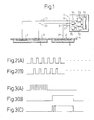
- Fig. 1 is a partial sectional view showing a first embodiment of the present invention.
- Figs. 2(A), 2(B) and Figs. 3(A) to (C) are views for explaining the operation of the embodiment shown in Fig. 1.
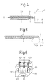
- Fig. 4 and Fig. 5 are views showing a second embodiment of the present invention.
- Fig. 6 is a view showing the configuration of a device at the time of performing experiments regarding the embodiment of the present invention.
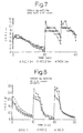
- Fig. 7 and Fig. 8 are views showing results of the experiments.
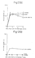
- Fig. 11 and Figs. 12(A) and (B) are views showing the results of Experiment 1.
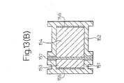
- Fig . 13 (B) is a sectional view of an experimental apparatus in the experiment on the embodiment of the present invention.
- Fig. 1 shows a block-diagram indicating one embodiment of a basic technical construction of the iontophoresis device in the present invention.
- the iontophoresis device of the present invention comprises; at least an electrode 1 or 2 to which a predetermined level of voltage, for example, predetermined pulses, is applied; a drug holding means 5 which carries ionic drugs therein and is arranged opposite to the electrode 1 or 2, the means being constructed so as to make contact with a portion to which a necessary therapy is required; and a voltage applying control means 7 for applying to the electrode 1 or 2 a pulse voltage having a predetermined voltage level at a predetermined timing.
- the electrode 1 or 2 comprises a reversible electrode so that a charge of ions released from the electrode 1 or 2 is supplied to the drug held inside the drug holding means 5 through a conductive solution.
- the reversible electrode 1 or 2 is additionally provided with a regeneration electrode 3.
- the iontophoresis device defined by the present invention has the above-mentioned basic technical constructions as well as the additional technical feature in that the reversible electrode 1 or 2 is accompanied by the regeneration electrode 3.
- the first aspect of the present invention provides an electrode structure provided integrally with a reversible electrode and an regeneration electrode for regeneration of the same and a regeneration current conducting means for conducting a current for regeneration of the reversible electrode when the therapeutic current is off so as thereby to prevent an electrode reaction of the main electrode and counter electrode impairing the conductivity or to restore the conductivity along with regeneration of the electrodes.
- Example 1 One embodiment of the iontophoresis device concerning the present invention will be explained as Example 1.
- Fig. 1, 1 is an electrode for the main electrode which is comprised of a metal material such as Ag. The material is selected in accordance with the polarity of the main electrode.
- Reference numeral 2 is an electrode for a counter electrode which is comprised of AgCl, Ag, etc.
- the material of the electrode 2 for the counter electrode is similar to the electrode 1 for the main electrode.
- a member with reversibility is selectively used for the electrode 1 for the main electrode and the electrode 2 for the counter electrode.
- Reversibility means that all or part of the electrode can be regenerated to the original material or the original conductivity. As a typical material, silver (Ag) is shown, but the invention is not limited to this.
- the polarities of the main electrode and the counter electrode are determined by the ionic polarities of the drug being administered and may be positive polarities or negative polarities.
- Reference numeral 3 is a regeneration electrode for regeneration use and is comprised of a conductive material such as carbon or aluminum.
- Reference numeral 4 is a backing member and is a sheet-like member having an electrical insulation ability.
- the electrodes 1 to 3 are attached to the surface of the backing member 4 by printing, adhesion by an adhesive, etc.
- Reference numeral 5 is a drug holding means which is comprised of a porous member etc. in which a drug and a solution are impregnated.
- a porous member As an example of a porous member, a water-absorbing and water-permeable film-like member is shown.
- illustration may be made of a laminar membrane filter (Biodyne A (trademark)), paper, nonwoven fabric, porous film, or other moisture-permeable fiber layer, starch (oblaat) formed by an aqueous polymer holding, adhered with, or containing a predetermined drug, a PVP film or other water-absorbing (water soluble) film, usually used to form a thin film. Further, the degree of the water solubility may be suitably adjusted in accordance with the purpose of use.
- a laminar membrane filter Biodyne A (trademark)
- paper nonwoven fabric, porous film, or other moisture-permeable fiber layer
- starch oblaat
- the degree of the water solubility may be suitably adjusted in accordance with the purpose of use.
- Reference numeral 6 is an interface forming means, which is comprised of a porous member as above, a gel substrate, etc. impregnated with a conductive solution.
- Reference numeral 7 is a power supply unit, whose internal structure will be explained below.
- Reference numeral 71 is a signal processing unit, which houses predetermined algorithmns and outputs control signals based on those algorithmns.
- the signal processing unit 71 is comprised by a gate array, a microcomputer, etc.
- Reference numeral 72 is a therapeutic current pulse output means, which outputs pulses and outputs depolarized pulses. The frequency and duty are not particularly limited.
- Reference numeral 73 is a regeneration electrical output means, which outputs a direct current, pulses, etc.
- the regeneration electrical output means 73 is controlled in accordance with need by the signal processing unit 71.
- Reference numerals 74 and 75 are switching means, which are comprised of analog switches, relays, transistors, FET's, etc.
- the switching means 74 and 75 perform an ON/OFF operation by control signals output by the signal processing means 71.
- One end of the output of the therapeutic current pulse output means 72 is connected to the output terminal (A), while the other end is connected to one end of the switching means 75.
- the other end of the switching means 75 is connected to the output terminal (C).
- One end of the regeneration electrical output means 73 is connected to the output terminal (A), while the other end is connected to one end of the switching means 74.
- the other end of the switching means 74 is connected to the output terminal (B).
- the depolarized pulse output means has the function of connecting the output terminals when the output pulse is off. For more details, see the description in Japanese Unexamined Patent Publication (Kokai) No. 60-156475.
- Reference numerals 11, 21, and 31 are lead wires, which electrically connect the output terminals (A) to (C) of the power supply unit 7 and the electrodes 1 to 3.
- the drug holding means 5 and interface forming means 6 of Fig. 1 are made to adjust the locations of percutaneous administration of the drug and the power supply unit 7.
- the signal processing means 71 turns on the switching means 75 and turns off the switching means 74.
- the therapeutic current pulse output means outputs the therapeutic current pulse and outputs the pulse shown in Fig. 2(A) to the output terminal (A) and the output terminal (C).
- the output terminal (B) is in a state electrically shut off from other output terminals since the switching means 74 is off.
- the output terminal (A) is connected to the electrode 1 of the main electrode, while the output terminal (C) is connected to the electrode 2 of the counter electrode.
- the pulse rises a closed electrical circuit is formed among the drug holding means 5, the human body, and the interface forming means 6 and the therapeutic current flows.
- the signal processing means 71 turns off the switching means 75 and turns on the switching means 74.
- the power supply unit 7 outputs a regeneration pulse shown in Fig. 2(B) between the output terminal (A) and the output terminal (B).
- the polarity of the pulse of the output terminal (A) is opposite to the polarity at the time of previous output of the therapeutic current. For example, if the output terminal (A) had a positive polarity at the time of output of the therapeutic current, the output terminal (A) has a negative polarity and the output terminal (B) has a positive polarity at the time of output of the regeneration pulse.
- the regeneration pulse output to the output terminal (B) and the output terminal (A) creates a closed electrical circuit among the regeneration electrode 3, the drug holding means 5, and the electrode 1 of the main electrode, applies a reverse direction voltage so as to prevent the electrode reaction of the electrode 1 of the main electrode, and thereby regenerates the conductivity.
- the output terminal (C) is set to become electrically shut off from the other output terminals since the switching means 75 is off. Further, when the electrical conductivity of the drug holding means 5 is high, the power supply unit 7 sometimes connects the resistor on the closed electrical circuit formed between the output terminal (B) and the output terminal (A) so as to prevent an overcharge current from being generated in this circuit when the operation for regenerating the electrode is carried out.
- the power supply unit 7 is not limited so long as it is provided with a battery or other power source and a pulse output means, depolarized pulse output means, direct current output means, and a device for controlling these output devices. Further, since the output current and voltage are relatively small, it is easy to make the key portions of the power supply unit 7 on a single chip.
- the above embodiment is one in which a regeneration pulse is output each time a therapeutic current pulse is output.
- a regeneration pulse is output each time a therapeutic current pulse is output.
- the power supply unit 7 outputs the therapeutic current pulse shown in Figs. 3(A) to 3(C) to the output terminal (A) and the output terminal (C) for exactly a predetermined period of time. At this time, the output terminal (B) is in a state electrically shut off from the other outputs.
- the regeneration direct current shown in Fig. 3(B) is output across the output terminal (B) and the output terminal (A) for a predetermined time. At this time, the output terminal (C) is in an electrically shut off state.
- the "direct current” spoken of here includes a pulse with a long pulse width.
- the regeneration pulse output across the output terminal (B) and the output terminal (A) may be, in addition to the direct current shown in Fig. 2(B), a group of successive pulses as shown in Fig. 3(C) or a depolarized pulse.
- the time the therapeutic current pulse is held may be several hours, for example, three hours or preferably six hours or so, but is not particularly limited. Further, the time the regeneration current output is held may be for example one hour, preferably three hours, but is not particularly limited.
- Example 2 an explanation will be made of another embodiment of the iontophoresis device of the present invention will be given as Example 2 with reference to Fig. 4.
- Reference numeral 1 is an electrode for the main electrode, and 3 is a regeneration electrode.
- the electrode 1 for the main electrode and the regeneration electrode 3 are both formed of conductive members having holes.
- Reference numeral 32 is a support member, which is formed by a nonconductive porous member such as a nonwoven fabric.
- the electrode 1 for the main electrode and the regeneration electrode 3 are printed on the front and rear of the support member 32 or are affixed to it by mechanical or chemical bonding.
- Reference numeral 5 is drug holding means which has the above-mentioned structure.
- Reference numeral 33 is a connecting member which is formed by a conductive member including the same material as the drug holding means 5.
- the lead wire 11 for connecting the electrode 1 for the main electrode with the power supply unit 7 shown in Fig. 1 and the lead wire 31 for connecting the regeneration electrode 3 and the power supply unit 7 are the same as those shown in Fig. 1.
- Figure 4 shows the construction with the electrode for the main electrode and the electrode for the counter electrode separated.
- the counter electrode side is shown by the same reference numerals and an illustration is omitted.
- the electrodes may be formed integrally as well as shown in Fig. 1. Further, the holes made in the electrode for the main electrode and the regeneration electrode are not particularly necessary. The point is that the drug holding means 5 and the connecting member 33 be of a structure forming an electrically conductive state through the support member 32.
- the electrical output of the power supply unit 7 is the same as that explained with reference to the operation of Fig. 1.
- the support member 32 is porous, so the drug holding means 5 and the connecting member 33 are electrically conducting through the solution.
- Example 3 Another embodiment of the ionophoresis device of the present invention will be explained as Example 3, with reference to Fig. 5.
- Figure 5 shows the drug holding means 5 shown in Fig. 1 inside of which has been interposed a regeneration electrode 3 having a mesh shape or holes.
- the rest of the construction is the same as in Fig. 1 and the operation is the same as in Fig. 2 and Fig. 3, so an explanation of these will be omitted.
- the regeneration electrode 3 may be a conductor member itself or may be a member comprised of a nonconductive sheet in which is made holes for attachment of the conductor member.
- Antihistamines .
- agents are mixed with various matrix components available in pharmaceutics and can be used in various types of forms such as salve, gel, cream, solution, suspension, film, or the like.
- the regeneration electrode may preferably be arranged integrally with the reversible electrode and further the regeneration electrode may preferably be controlled by the voltage applying controlling means so that the regeneration electrode is supplied with predetermined pulses at a timing at which predetermined pulses are not applied to the reversible electrode.
- At least two reversible electrodes are provided in the iontophoresis device and two of the reversible electrodes, selected from among them, preferably form a pair as one group, and in that each one of the reversible electrodes forming the pair, is supplied with the pulses.
- the pulse phase of the pulses applied to one of the reversible electrodes in the pair is different from that of the pulses applied to another reversible electrode in the pair.
- the regeneration electrode provided in the iontophoresis device is arranged at a position close to one of the reversible electrodes forming the pair of group, and more particularly, the regeneration electrode may be provided on a plane of the device identical to the plane on which the reversible electrode is provided or may be provided to form a construction in which the regeneration electrode is stacked with the reversible electrode through a supporting means interposed therebetween.
- Reference numeral 61 is an anode use electrode (main electrode), which is comprised of silver (Ag) foil.
- Reference numeral 62 is an anode use electrode (regeneration electrode) comprised of a carbon printed film electrode.
- Reference numeral 63 is a cathode use electrode (counter electrode) which is comprised of an AgCl/Ag foil.
- Reference numeral 64 is a physiological saline solution, while 65 is a stirrer.
- the distance between electrodes was made 25 mm and the electrical output device for the therapeutic current used was a 2V, 40 kHz, 30 percent duty depolarized pulse output device.
- the regeneration use electrical output device used was also a depolarized pulse output device similar to the above.
- the electrodes 61 to 63 and the electrical output means were connected by conductor terminals 611 to 631.
- Fig. 7 The graph represented by a symbol ⁇ in Fig. 7, shows a first embodiment of the above-mentioned test result and the graph shows the relationship between the electrical current for therapeutic current Im and time for the therapeutic treatment.
- the graph indicates that although the initial current value Im (measured at the time 0) shows 8 mA, the current value Im was reduced to 3.5 mA when 20 minutes (20 min) has passed. Thereafter, in this period, the electrical current for therapeutic current Im was once stopped and the regenerating operation as defined by the present invention was carried out (a first regenerating operation). After this regenerating operation was completed, the second electrical current for therapeutic current Im was again supplied.
- the electrical current for therapeutic current Im was again stopped and the regenerating operation as defined by the present invention was carried out (a second regenerating operation). After this regenerating operation was completed, the third electrical current for therapeutic current Im was again supplied.
- the value of the electrical current exceeded the initial current value of 8 mA and it increased to 9 and 10 mA, respectively.
- the present invention has the effect that it is able to restore conductivity by preventing an electrode reaction impairing the conductivity or by regeneration of the electrode and enables stable, effective administration of a drug over a long period.
- the abdominal skin 157 of seven week old hairless rats was excised and was attached, with the corneal layer facing the drug container side, to the two-container type horizontal diffusion cell (drug transmission area: 2.54 cm 2 ) of the basic structure shown in Fig. 13(B).
- the drug container 151 and drug receiving container 152 were filled with 1.5 percent aqueous dexamethasone sodium phosphate solution 153 and phosphate buffered saline solution (PBS) 154, respectively.
- PBS phosphate buffered saline solution
- Figures 12(A) and (B) show the changes along with time in the average current (1m) at the time of the experiment and the effective current (Ie), which is comprised of the average current minus the current component flowing in the opposite direction at the time of depolarization.
- Ie effective current
- the iontophoresis electrode structure of the present invention it is possible to improve the efficiency of drug transmission in the case of use of a reversible (nonpolarized) electrode such as a silver chloride electrode where chlorine ions etc. are discharged along with conduction and the transport rate of the drug falls. Accordingly, the use of the electrode structure of the present invention leads to an improved feeling of use accompanying the reduction of the irritation to the skin at the time of performance of iontophoresis due to the pulse depolarization method etc. and a reduction in weight of the battery used.
Landscapes
- Health & Medical Sciences (AREA)
- Engineering & Computer Science (AREA)
- Biomedical Technology (AREA)
- Nuclear Medicine, Radiotherapy & Molecular Imaging (AREA)
- Radiology & Medical Imaging (AREA)
- Life Sciences & Earth Sciences (AREA)
- Animal Behavior & Ethology (AREA)
- General Health & Medical Sciences (AREA)
- Public Health (AREA)
- Veterinary Medicine (AREA)
- Bioinformatics & Cheminformatics (AREA)
- Electrotherapy Devices (AREA)
- Medicinal Preparation (AREA)
Abstract
Description
- I:
- current value (A)
- t:
- time (seconds)
- F:
- Faraday constant 9.65 × 10⁴ (c/mol)
- W:
- Mass of reaction substance (g)
- Me:
- Chemical equivalents (g/mol)
Claims (11)
- An iontophoresis device comprising:characterized in that a regeneration electrode (3) is additionally provided and in that said regeneration electrode (3) and said first reversible electrode (1) are arranged within said drug holding means (5).at least two reversible electrodes (1,2) to which a predetermined voltage level is applied;a drug holding means (5) which carries ionic drugs therein and is arranged opposite to a first reversible electrode (1), said drug holding means (5) being constructed so as to make contact with a portion for which a necessary therapy is required;a voltage applying control means (7) for applying to said first reversible electrode (1) a voltage having a predetermined voltage level at a predetermined timing, so that a charge of ions released from said first reversible electrode (1) is supplied to said drug held inside said drug holding means (5) through a conductive solution;
- An iontophoresis device according to claim 1, wherein said regeneration electrode (3) and said first reversible electrode (1) form an integral electrode structure.
- An iontophoresis device according to claim 1, wherein said regeneration electrode (3) is supplied with predetermined pulses at a timing where predetermined pulses are not applied to said reversible electrode (1).
- An iontophoresis device according to claim 1, wherein said regeneration electrode (3) is supplied with a predetermined voltage selected from a direct current voltage and a pulse voltage.
- An iontophoresis device according to any one of claims 1 to 4, wherein two of said reversible electrodes (1,2) are selected from among them to form a pair.
- An iontophoresis device according to claim 5, wherein each one of said reversible electrodes (1,2) forming said pair is supplied with said pulses, wherein the phase of said pulses applied to one of said reversible electrodes (1) in said pair, is different from that of said pulses applied to the other reversible electrode (2) in said pair.
- An iontophoresis device according to claim 5, wherein said regeneration electrode (3) is provided at a position close to at least one of said reversible electrodes (1) forming said pair.
- An iontophoresis device according to claim 1, wherein said regeneration electrode (3) is provided on a plane of said device identical to the plane on which said first reversible electrode (1) is provided.
- An iontophoresis device according to claim 1, wherein said regeneration electrode (3) is provided to form a construction in which said regeneration electrode (3) is stacked with said first reversible electrode (1) through a supporting means (32) interposed therebetween.
- An iontophoresis device according to claim 9, wherein at least one of said regeneration electrode (3) and said first reversible electrode (1) is made of a material having a function enabling water to penetrate therethrough.
- An iontophoresis device according to claim 9, wherein said supporting means (32) is made of a material having a function enabling water to penetrate therethrough.
Priority Applications (1)
| Application Number | Priority Date | Filing Date | Title |
|---|---|---|---|
| EP01124758A EP1195175A3 (en) | 1993-06-23 | 1994-06-23 | Iontoporesis device |
Applications Claiming Priority (7)
| Application Number | Priority Date | Filing Date | Title |
|---|---|---|---|
| JP17464593 | 1993-06-23 | ||
| JP174645/93 | 1993-06-23 | ||
| JP17464593 | 1993-06-23 | ||
| JP183399/93 | 1993-06-30 | ||
| JP18339993 | 1993-06-30 | ||
| JP18339993 | 1993-06-30 | ||
| PCT/JP1994/001013 WO1995000200A1 (en) | 1993-06-23 | 1994-06-23 | Iontophoresis device |
Related Child Applications (1)
| Application Number | Title | Priority Date | Filing Date |
|---|---|---|---|
| EP01124758.2 Division-Into | 2001-10-17 |
Publications (3)
| Publication Number | Publication Date |
|---|---|
| EP0705619A1 EP0705619A1 (en) | 1996-04-10 |
| EP0705619A4 EP0705619A4 (en) | 1996-08-07 |
| EP0705619B1 true EP0705619B1 (en) | 2002-08-14 |
Family
ID=26496190
Family Applications (2)
| Application Number | Title | Priority Date | Filing Date |
|---|---|---|---|
| EP94918562A Expired - Lifetime EP0705619B1 (en) | 1993-06-23 | 1994-06-23 | Iontophoresis device |
| EP01124758A Withdrawn EP1195175A3 (en) | 1993-06-23 | 1994-06-23 | Iontoporesis device |
Family Applications After (1)
| Application Number | Title | Priority Date | Filing Date |
|---|---|---|---|
| EP01124758A Withdrawn EP1195175A3 (en) | 1993-06-23 | 1994-06-23 | Iontoporesis device |
Country Status (9)
| Country | Link |
|---|---|
| US (1) | US5620580A (en) |
| EP (2) | EP0705619B1 (en) |
| KR (1) | KR100194851B1 (en) |
| AT (1) | ATE222131T1 (en) |
| AU (1) | AU691502B2 (en) |
| CA (1) | CA2126487C (en) |
| DE (1) | DE69431189T2 (en) |
| TW (1) | TW252921B (en) |
| WO (1) | WO1995000200A1 (en) |
Families Citing this family (56)
| Publication number | Priority date | Publication date | Assignee | Title |
|---|---|---|---|---|
| JP3565903B2 (en) * | 1994-06-25 | 2004-09-15 | 久光製薬株式会社 | Electrode structure for iontophoresis |
| DE69633733T2 (en) * | 1995-08-31 | 2006-02-02 | Hisamitsu Pharmaceutical Co., Inc., Tosu | IONTOPHORETIC DEVICE AND CORRESPONDING METHOD FOR CONTROLLING THE ELECTRICITY |
| WO1998002207A1 (en) * | 1996-07-12 | 1998-01-22 | Empi, Inc. | Iontophoresis electrode |
| US5941843A (en) * | 1996-07-12 | 1999-08-24 | Empi, Inc. | Iontophoresis electrode |
| US5857994A (en) * | 1996-10-01 | 1999-01-12 | Becton, Dickinson And Company | Awakenable iontophoretic/delivery device for reducing electrical sensation upon application thereof |
| US6775569B2 (en) * | 1997-11-05 | 2004-08-10 | Hisamitsu Pharmaceutical Co., Inc. | Electroporation device for in vivo delivery of therapeutic agents |
| JP2002536133A (en) | 1999-02-10 | 2002-10-29 | ジーエムピー ドラッグ デリバリー インコーポレイテッド | Iontophoretic, electroporation and combination patches for local drug delivery |
| US7127285B2 (en) * | 1999-03-12 | 2006-10-24 | Transport Pharmaceuticals Inc. | Systems and methods for electrokinetic delivery of a substance |
| US6327496B1 (en) | 1999-07-12 | 2001-12-04 | Empi Corp. | Iontophoresis electrode |
| CA2400325A1 (en) | 2000-02-18 | 2001-08-23 | University Of Utah Research Foundation | Methods for delivering agents using alternating current |
| AU2001241483A1 (en) | 2000-02-18 | 2001-08-27 | University Of Utah Research Foundation | Methods for extracting substances using alternating current |
| US7137975B2 (en) * | 2001-02-13 | 2006-11-21 | Aciont, Inc. | Method for increasing the battery life of an alternating current iontophoresis device using a barrier-modifying agent |
| US20030096275A1 (en) * | 2001-08-20 | 2003-05-22 | Laing Lance G. | Biosensor for small molecule analytes |
| US8722235B2 (en) | 2004-04-21 | 2014-05-13 | Blue Spark Technologies, Inc. | Thin printable flexible electrochemical cell and method of making the same |
| US8029927B2 (en) | 2005-03-22 | 2011-10-04 | Blue Spark Technologies, Inc. | Thin printable electrochemical cell utilizing a “picture frame” and methods of making the same |
| US8722233B2 (en) | 2005-05-06 | 2014-05-13 | Blue Spark Technologies, Inc. | RFID antenna-battery assembly and the method to make the same |
| JP2006346368A (en) * | 2005-06-20 | 2006-12-28 | Transcutaneous Technologies Inc | Iontophoresis apparatus and manufacturing method |
| EP1905433A1 (en) * | 2005-07-15 | 2008-04-02 | Transcu Ltd. | Percutaneous absorption patch with application position indicating function, and iontophoresis device |
| JP2007037868A (en) * | 2005-08-05 | 2007-02-15 | Transcutaneous Technologies Inc | Transdermal administration device and its controlling method |
| US8386030B2 (en) * | 2005-08-08 | 2013-02-26 | Tti Ellebeau, Inc. | Iontophoresis device |
| US20070060860A1 (en) * | 2005-08-18 | 2007-03-15 | Transcutaneous Technologies Inc. | Iontophoresis device |
| JPWO2007026671A1 (en) * | 2005-08-29 | 2009-03-05 | Tti・エルビュー株式会社 | An iontophoresis device that selects a drug to be administered based on information from a sensor |
| US20100030128A1 (en) * | 2005-09-06 | 2010-02-04 | Kazuma Mitsuguchi | Iontophoresis device |
| BRPI0616165A2 (en) * | 2005-09-15 | 2011-06-07 | Tti Ellebeau Inc | rod type iontophoresis device |
| AU2006289888B2 (en) * | 2005-09-16 | 2010-12-02 | Tti Ellebeau, Inc. | Catheter type iontophoresis apparatus |
| WO2007038028A1 (en) * | 2005-09-28 | 2007-04-05 | Tti Ellebeau, Inc. | Iontophoresis apparatus and method to deliver active agents to biological interfaces |
| US20070071807A1 (en) * | 2005-09-28 | 2007-03-29 | Hidero Akiyama | Capsule-type drug-releasing device and capsule-type drug-releasing device system |
| JPWO2007037476A1 (en) * | 2005-09-30 | 2009-04-16 | Tti・エルビュー株式会社 | Iontophoresis device for controlling the dosage and timing of sleep inducers and stimulants |
| US20070078445A1 (en) * | 2005-09-30 | 2007-04-05 | Curt Malloy | Synchronization apparatus and method for iontophoresis device to deliver active agents to biological interfaces |
| JP2009509691A (en) * | 2005-09-30 | 2009-03-12 | Tti・エルビュー株式会社 | An iontophoresis device for delivering multiple active substances to a biological interface |
| US20070232983A1 (en) * | 2005-09-30 | 2007-10-04 | Smith Gregory A | Handheld apparatus to deliver active agents to biological interfaces |
| WO2007037475A1 (en) * | 2005-09-30 | 2007-04-05 | Tti Ellebeau, Inc. | Electrode structure for iontophoresis comprising shape memory separator, and iontophoresis apparatus comprising the same |
| US20070197955A1 (en) * | 2005-10-12 | 2007-08-23 | Transcutaneous Technologies Inc. | Mucous membrane adhesion-type iontophoresis device |
| JP4804904B2 (en) * | 2005-12-09 | 2011-11-02 | Tti・エルビュー株式会社 | Iontophoresis device packaging |
| US20080033338A1 (en) * | 2005-12-28 | 2008-02-07 | Smith Gregory A | Electroosmotic pump apparatus and method to deliver active agents to biological interfaces |
| US20080033398A1 (en) * | 2005-12-29 | 2008-02-07 | Transcutaneous Technologies Inc. | Device and method for enhancing immune response by electrical stimulation |
| WO2007123707A1 (en) * | 2006-03-30 | 2007-11-01 | Tti Ellebeau, Inc. | Controlled release membrane and methods of use |
| WO2008005458A2 (en) * | 2006-07-05 | 2008-01-10 | Tti Ellebeau, Inc. | Delivery device having self-assembling dendritic polymers and method of use thereof |
| CA2661879A1 (en) * | 2006-09-05 | 2008-03-13 | Tti Ellebeau, Inc. | Transdermal drug delivery systems, devices, and methods using inductive power supplies |
| WO2008070524A2 (en) * | 2006-12-01 | 2008-06-12 | Tti Ellebeau, Inc. | Systems, devices, and methods for powering and/or controlling devices, for instance transdermal delivery devices |
| EP2176814A4 (en) | 2007-07-18 | 2012-06-13 | Blue Spark Technologies Inc | Integrated electronic device and methods of making the same |
| US20120118741A1 (en) * | 2007-08-01 | 2012-05-17 | Blue Spark Technologies, Inc. | Integrated Electronic Device and Methods of Making the Same |
| US8574754B2 (en) | 2007-12-19 | 2013-11-05 | Blue Spark Technologies, Inc. | High current thin electrochemical cell and methods of making the same |
| WO2009153019A1 (en) * | 2008-06-19 | 2009-12-23 | Lts Lohmann Therapie-Systeme Ag | Composition for transdermal delivery of cationic active agents |
| CA2736495A1 (en) * | 2008-09-10 | 2010-03-18 | Gregory A. Smith | Apparatus and method to dispense hpc-based viscous liquids into porous substrates, e.g., continuous web-based process |
| JP2012529353A (en) * | 2009-06-09 | 2012-11-22 | Tti・エルビュー株式会社 | Long-life high-capacity electrode, apparatus and manufacturing method |
| WO2013044224A2 (en) | 2011-09-22 | 2013-03-28 | Blue Spark Technologies, Inc. | Cell attachment method |
| WO2013177202A1 (en) | 2012-05-21 | 2013-11-28 | Blue Spark Technologies, Inc. | Multi-cell battery |
| CN104936513B (en) | 2012-11-01 | 2018-01-12 | 蓝色火花科技有限公司 | Temperature recording paster |
| US9444078B2 (en) | 2012-11-27 | 2016-09-13 | Blue Spark Technologies, Inc. | Battery cell construction |
| US9693689B2 (en) | 2014-12-31 | 2017-07-04 | Blue Spark Technologies, Inc. | Body temperature logging patch |
| WO2017119520A1 (en) * | 2016-01-05 | 2017-07-13 | 바이오센서연구소 주식회사 | Facial mask using reverse electrodialysis and kit comprising same |
| SG11201703913YA (en) * | 2016-01-05 | 2017-08-30 | Biosensor Laboratories Inc | Iontophoresis Device For Drug Delivery And Method For Manufacturing The Same |
| GB2554455A (en) * | 2016-09-29 | 2018-04-04 | Feeligreen Sa | Skin treatment device and method for delivery of an active ingredient into the human skin by means of iontophoresis, using an array of electrodes |
| US10849501B2 (en) | 2017-08-09 | 2020-12-01 | Blue Spark Technologies, Inc. | Body temperature logging patch |
| CN113713248B (en) * | 2021-09-08 | 2022-07-05 | 北京意安平顺网络科技有限公司 | Iontophoresis device for skin and patch thereof |
Family Cites Families (14)
| Publication number | Priority date | Publication date | Assignee | Title |
|---|---|---|---|---|
| US4846950A (en) * | 1983-09-08 | 1989-07-11 | Montefiore Hospital Assn Of Western Pa | Cyclic controlled electrolysis apparatus |
| US4731049A (en) * | 1987-01-30 | 1988-03-15 | Ionics, Incorporated | Cell for electrically controlled transdermal drug delivery |
| US5080646A (en) * | 1988-10-03 | 1992-01-14 | Alza Corporation | Membrane for electrotransport transdermal drug delivery |
| US4927408A (en) * | 1988-10-03 | 1990-05-22 | Alza Corporation | Electrotransport transdermal system |
| US5057072A (en) * | 1988-10-28 | 1991-10-15 | Medtronic, Inc. | Iontophoresis electrode |
| US5320597A (en) * | 1991-02-08 | 1994-06-14 | Becton, Dickinson And Company | Device and method for renewing electrodes during iontophoresis |
| AU651803B2 (en) * | 1989-12-14 | 1994-08-04 | Regents Of The University Of California, The | Method for increasing the service life of an implantable sensor |
| US5084008A (en) * | 1989-12-22 | 1992-01-28 | Medtronic, Inc. | Iontophoresis electrode |
| US5125894A (en) * | 1990-03-30 | 1992-06-30 | Alza Corporation | Method and apparatus for controlled environment electrotransport |
| US5084006A (en) * | 1990-03-30 | 1992-01-28 | Alza Corporation | Iontopheretic delivery device |
| US5224927A (en) * | 1990-11-01 | 1993-07-06 | Robert Tapper | Iontophoretic treatment system |
| JPH04224770A (en) * | 1990-12-26 | 1992-08-14 | Teijin Ltd | Apparatus for iontophoresis |
| FR2687321B1 (en) * | 1992-02-14 | 1999-04-16 | Elf Aquitaine | IONOPHORESIS DEVICE FOR THE TRANSCUTANEOUS ADMINISTRATION OF A TOTAL QUANTITY GIVEN FROM AN ACTIVE PRINCIPLE TO A SUBJECT. |
| US5298017A (en) * | 1992-12-29 | 1994-03-29 | Alza Corporation | Layered electrotransport drug delivery system |
-
1994
- 1994-06-22 CA CA002126487A patent/CA2126487C/en not_active Expired - Fee Related
- 1994-06-23 KR KR1019950705858A patent/KR100194851B1/en not_active IP Right Cessation
- 1994-06-23 EP EP94918562A patent/EP0705619B1/en not_active Expired - Lifetime
- 1994-06-23 US US08/265,710 patent/US5620580A/en not_active Expired - Fee Related
- 1994-06-23 AT AT94918562T patent/ATE222131T1/en not_active IP Right Cessation
- 1994-06-23 TW TW083105707A patent/TW252921B/zh not_active IP Right Cessation
- 1994-06-23 DE DE69431189T patent/DE69431189T2/en not_active Expired - Fee Related
- 1994-06-23 WO PCT/JP1994/001013 patent/WO1995000200A1/en active IP Right Grant
- 1994-06-23 AU AU69831/94A patent/AU691502B2/en not_active Ceased
- 1994-06-23 EP EP01124758A patent/EP1195175A3/en not_active Withdrawn
Also Published As
| Publication number | Publication date |
|---|---|
| EP1195175A3 (en) | 2004-01-28 |
| ATE222131T1 (en) | 2002-08-15 |
| US5620580A (en) | 1997-04-15 |
| DE69431189T2 (en) | 2003-04-17 |
| WO1995000200A1 (en) | 1995-01-05 |
| KR960703025A (en) | 1996-06-19 |
| KR100194851B1 (en) | 1999-06-15 |
| AU691502B2 (en) | 1998-05-21 |
| DE69431189D1 (en) | 2002-09-19 |
| AU6983194A (en) | 1995-01-17 |
| CA2126487A1 (en) | 1994-12-24 |
| TW252921B (en) | 1995-08-01 |
| CA2126487C (en) | 2001-05-29 |
| EP0705619A1 (en) | 1996-04-10 |
| EP1195175A2 (en) | 2002-04-10 |
| EP0705619A4 (en) | 1996-08-07 |
Similar Documents
| Publication | Publication Date | Title |
|---|---|---|
| EP0705619B1 (en) | Iontophoresis device | |
| US6490482B2 (en) | Apparatus and method for in vivo delivery of therapeutic agents | |
| KR100535732B1 (en) | Electrotransport electrode assembly having lower initial resistance | |
| JP4165659B2 (en) | Electrotransport dosing device with improved safety and reduced abuse potential | |
| US5221254A (en) | Method for reducing sensation in iontophoretic drug delivery | |
| AU696832B2 (en) | Iontophoresis system and its control process of current | |
| EP1036573B1 (en) | Device for delivering drug through skin or mucosa | |
| IE83316B1 (en) | Device for reducing sensation during iontophoretic drug delivery | |
| JPH05506165A (en) | Delivery device for iontophoresis | |
| WO1999043382A1 (en) | Iontophoresis device | |
| JP2809510B2 (en) | System for iontophoresis | |
| US6104951A (en) | Iontophoresis electrode structure | |
| JP3247931B2 (en) | Iontophoresis electrode device | |
| JP2856551B2 (en) | Device for iontophoresis | |
| JPH09187520A (en) | Percutaneous or permucosal drug transmission method |
Legal Events
| Date | Code | Title | Description |
|---|---|---|---|
| PUAI | Public reference made under article 153(3) epc to a published international application that has entered the european phase |
Free format text: ORIGINAL CODE: 0009012 |
|
| 17P | Request for examination filed |
Effective date: 19951216 |
|
| AK | Designated contracting states |
Kind code of ref document: A1 Designated state(s): AT BE CH DE DK ES FR GB GR IE IT LI LU MC NL PT SE |
|
| A4 | Supplementary search report drawn up and despatched |
Effective date: 19960625 |
|
| AK | Designated contracting states |
Kind code of ref document: A4 Designated state(s): AT BE CH DE DK ES FR GB GR IE IT LI LU MC NL PT SE |
|
| 17Q | First examination report despatched |
Effective date: 20000105 |
|
| GRAG | Despatch of communication of intention to grant |
Free format text: ORIGINAL CODE: EPIDOS AGRA |
|
| GRAG | Despatch of communication of intention to grant |
Free format text: ORIGINAL CODE: EPIDOS AGRA |
|
| GRAH | Despatch of communication of intention to grant a patent |
Free format text: ORIGINAL CODE: EPIDOS IGRA |
|
| GRAH | Despatch of communication of intention to grant a patent |
Free format text: ORIGINAL CODE: EPIDOS IGRA |
|
| GRAA | (expected) grant |
Free format text: ORIGINAL CODE: 0009210 |
|
| AK | Designated contracting states |
Kind code of ref document: B1 Designated state(s): AT BE CH DE DK ES FR GB GR IE IT LI LU MC NL PT SE |
|
| PG25 | Lapsed in a contracting state [announced via postgrant information from national office to epo] |
Ref country code: GR Free format text: LAPSE BECAUSE OF FAILURE TO SUBMIT A TRANSLATION OF THE DESCRIPTION OR TO PAY THE FEE WITHIN THE PRESCRIBED TIME-LIMIT Effective date: 20020814 Ref country code: BE Free format text: LAPSE BECAUSE OF FAILURE TO SUBMIT A TRANSLATION OF THE DESCRIPTION OR TO PAY THE FEE WITHIN THE PRESCRIBED TIME-LIMIT Effective date: 20020814 Ref country code: AT Free format text: LAPSE BECAUSE OF FAILURE TO SUBMIT A TRANSLATION OF THE DESCRIPTION OR TO PAY THE FEE WITHIN THE PRESCRIBED TIME-LIMIT Effective date: 20020814 |
|
| REF | Corresponds to: |
Ref document number: 222131 Country of ref document: AT Date of ref document: 20020815 Kind code of ref document: T |
|
| REG | Reference to a national code |
Ref country code: GB Ref legal event code: FG4D |
|
| REG | Reference to a national code |
Ref country code: CH Ref legal event code: EP |
|
| REG | Reference to a national code |
Ref country code: CH Ref legal event code: NV Representative=s name: MOINAS & SAVOYE SA |
|
| REG | Reference to a national code |
Ref country code: IE Ref legal event code: FG4D |
|
| REF | Corresponds to: |
Ref document number: 69431189 Country of ref document: DE Date of ref document: 20020919 |
|
| PG25 | Lapsed in a contracting state [announced via postgrant information from national office to epo] |
Ref country code: SE Free format text: LAPSE BECAUSE OF FAILURE TO SUBMIT A TRANSLATION OF THE DESCRIPTION OR TO PAY THE FEE WITHIN THE PRESCRIBED TIME-LIMIT Effective date: 20021114 Ref country code: DK Free format text: LAPSE BECAUSE OF FAILURE TO SUBMIT A TRANSLATION OF THE DESCRIPTION OR TO PAY THE FEE WITHIN THE PRESCRIBED TIME-LIMIT Effective date: 20021114 |
|
| PG25 | Lapsed in a contracting state [announced via postgrant information from national office to epo] |
Ref country code: PT Free format text: LAPSE BECAUSE OF FAILURE TO SUBMIT A TRANSLATION OF THE DESCRIPTION OR TO PAY THE FEE WITHIN THE PRESCRIBED TIME-LIMIT Effective date: 20021128 |
|
| ET | Fr: translation filed | ||
| PG25 | Lapsed in a contracting state [announced via postgrant information from national office to epo] |
Ref country code: ES Free format text: LAPSE BECAUSE OF FAILURE TO SUBMIT A TRANSLATION OF THE DESCRIPTION OR TO PAY THE FEE WITHIN THE PRESCRIBED TIME-LIMIT Effective date: 20030228 |
|
| PLBE | No opposition filed within time limit |
Free format text: ORIGINAL CODE: 0009261 |
|
| STAA | Information on the status of an ep patent application or granted ep patent |
Free format text: STATUS: NO OPPOSITION FILED WITHIN TIME LIMIT |
|
| PG25 | Lapsed in a contracting state [announced via postgrant information from national office to epo] |
Ref country code: LU Free format text: LAPSE BECAUSE OF NON-PAYMENT OF DUE FEES Effective date: 20030623 Ref country code: IE Free format text: LAPSE BECAUSE OF NON-PAYMENT OF DUE FEES Effective date: 20030623 |
|
| PG25 | Lapsed in a contracting state [announced via postgrant information from national office to epo] |
Ref country code: MC Free format text: LAPSE BECAUSE OF NON-PAYMENT OF DUE FEES Effective date: 20030630 |
|
| 26N | No opposition filed |
Effective date: 20030515 |
|
| REG | Reference to a national code |
Ref country code: IE Ref legal event code: MM4A |
|
| PGFP | Annual fee paid to national office [announced via postgrant information from national office to epo] |
Ref country code: CH Payment date: 20070614 Year of fee payment: 14 |
|
| PGFP | Annual fee paid to national office [announced via postgrant information from national office to epo] |
Ref country code: NL Payment date: 20070617 Year of fee payment: 14 |
|
| PGFP | Annual fee paid to national office [announced via postgrant information from national office to epo] |
Ref country code: DE Payment date: 20070621 Year of fee payment: 14 |
|
| PGFP | Annual fee paid to national office [announced via postgrant information from national office to epo] |
Ref country code: GB Payment date: 20070620 Year of fee payment: 14 |
|
| PGFP | Annual fee paid to national office [announced via postgrant information from national office to epo] |
Ref country code: IT Payment date: 20070618 Year of fee payment: 14 |
|
| PGFP | Annual fee paid to national office [announced via postgrant information from national office to epo] |
Ref country code: FR Payment date: 20070608 Year of fee payment: 14 |
|
| REG | Reference to a national code |
Ref country code: CH Ref legal event code: PL |
|
| GBPC | Gb: european patent ceased through non-payment of renewal fee |
Effective date: 20080623 |
|
| NLV4 | Nl: lapsed or anulled due to non-payment of the annual fee |
Effective date: 20090101 |
|
| REG | Reference to a national code |
Ref country code: FR Ref legal event code: ST Effective date: 20090228 |
|
| PG25 | Lapsed in a contracting state [announced via postgrant information from national office to epo] |
Ref country code: DE Free format text: LAPSE BECAUSE OF NON-PAYMENT OF DUE FEES Effective date: 20090101 |
|
| PG25 | Lapsed in a contracting state [announced via postgrant information from national office to epo] |
Ref country code: NL Free format text: LAPSE BECAUSE OF NON-PAYMENT OF DUE FEES Effective date: 20090101 |
|
| PG25 | Lapsed in a contracting state [announced via postgrant information from national office to epo] |
Ref country code: LI Free format text: LAPSE BECAUSE OF NON-PAYMENT OF DUE FEES Effective date: 20080630 Ref country code: GB Free format text: LAPSE BECAUSE OF NON-PAYMENT OF DUE FEES Effective date: 20080623 Ref country code: CH Free format text: LAPSE BECAUSE OF NON-PAYMENT OF DUE FEES Effective date: 20080630 |
|
| PG25 | Lapsed in a contracting state [announced via postgrant information from national office to epo] |
Ref country code: IT Free format text: LAPSE BECAUSE OF NON-PAYMENT OF DUE FEES Effective date: 20080623 Ref country code: FR Free format text: LAPSE BECAUSE OF NON-PAYMENT OF DUE FEES Effective date: 20080630 |