EP0705577A1 - High strength and high density intraluminar wire stent - Google Patents
High strength and high density intraluminar wire stent Download PDFInfo
- Publication number
- EP0705577A1 EP0705577A1 EP95302879A EP95302879A EP0705577A1 EP 0705577 A1 EP0705577 A1 EP 0705577A1 EP 95302879 A EP95302879 A EP 95302879A EP 95302879 A EP95302879 A EP 95302879A EP 0705577 A1 EP0705577 A1 EP 0705577A1
- Authority
- EP
- European Patent Office
- Prior art keywords
- wire
- stent
- waves
- wave
- longitudinally
- Prior art date
- Legal status (The legal status is an assumption and is not a legal conclusion. Google has not performed a legal analysis and makes no representation as to the accuracy of the status listed.)
- Granted
Links
Images


Classifications
-
- A—HUMAN NECESSITIES
- A61—MEDICAL OR VETERINARY SCIENCE; HYGIENE
- A61F—FILTERS IMPLANTABLE INTO BLOOD VESSELS; PROSTHESES; DEVICES PROVIDING PATENCY TO, OR PREVENTING COLLAPSING OF, TUBULAR STRUCTURES OF THE BODY, e.g. STENTS; ORTHOPAEDIC, NURSING OR CONTRACEPTIVE DEVICES; FOMENTATION; TREATMENT OR PROTECTION OF EYES OR EARS; BANDAGES, DRESSINGS OR ABSORBENT PADS; FIRST-AID KITS
- A61F2/00—Filters implantable into blood vessels; Prostheses, i.e. artificial substitutes or replacements for parts of the body; Appliances for connecting them with the body; Devices providing patency to, or preventing collapsing of, tubular structures of the body, e.g. stents
- A61F2/82—Devices providing patency to, or preventing collapsing of, tubular structures of the body, e.g. stents
- A61F2/86—Stents in a form characterised by the wire-like elements; Stents in the form characterised by a net-like or mesh-like structure
- A61F2/88—Stents in a form characterised by the wire-like elements; Stents in the form characterised by a net-like or mesh-like structure the wire-like elements formed as helical or spiral coils
-
- B—PERFORMING OPERATIONS; TRANSPORTING
- B21—MECHANICAL METAL-WORKING WITHOUT ESSENTIALLY REMOVING MATERIAL; PUNCHING METAL
- B21F—WORKING OR PROCESSING OF METAL WIRE
- B21F45/00—Wire-working in the manufacture of other particular articles
- B21F45/008—Wire-working in the manufacture of other particular articles of medical instruments, e.g. stents, corneal rings
-
- A—HUMAN NECESSITIES
- A61—MEDICAL OR VETERINARY SCIENCE; HYGIENE
- A61F—FILTERS IMPLANTABLE INTO BLOOD VESSELS; PROSTHESES; DEVICES PROVIDING PATENCY TO, OR PREVENTING COLLAPSING OF, TUBULAR STRUCTURES OF THE BODY, e.g. STENTS; ORTHOPAEDIC, NURSING OR CONTRACEPTIVE DEVICES; FOMENTATION; TREATMENT OR PROTECTION OF EYES OR EARS; BANDAGES, DRESSINGS OR ABSORBENT PADS; FIRST-AID KITS
- A61F2/00—Filters implantable into blood vessels; Prostheses, i.e. artificial substitutes or replacements for parts of the body; Appliances for connecting them with the body; Devices providing patency to, or preventing collapsing of, tubular structures of the body, e.g. stents
- A61F2/02—Prostheses implantable into the body
- A61F2/04—Hollow or tubular parts of organs, e.g. bladders, tracheae, bronchi or bile ducts
- A61F2/06—Blood vessels
- A61F2/07—Stent-grafts
-
- A—HUMAN NECESSITIES
- A61—MEDICAL OR VETERINARY SCIENCE; HYGIENE
- A61F—FILTERS IMPLANTABLE INTO BLOOD VESSELS; PROSTHESES; DEVICES PROVIDING PATENCY TO, OR PREVENTING COLLAPSING OF, TUBULAR STRUCTURES OF THE BODY, e.g. STENTS; ORTHOPAEDIC, NURSING OR CONTRACEPTIVE DEVICES; FOMENTATION; TREATMENT OR PROTECTION OF EYES OR EARS; BANDAGES, DRESSINGS OR ABSORBENT PADS; FIRST-AID KITS
- A61F2220/00—Fixations or connections for prostheses classified in groups A61F2/00 - A61F2/26 or A61F2/82 or A61F9/00 or A61F11/00 or subgroups thereof
- A61F2220/0025—Connections or couplings between prosthetic parts, e.g. between modular parts; Connecting elements
- A61F2220/0058—Connections or couplings between prosthetic parts, e.g. between modular parts; Connecting elements soldered or brazed or welded
Definitions
- the present invention relates generally to implantable intraluminal stents and more particularly, the present invention relates to an improved high strength intraluminal stent having increased wire density.
- Intraluminal devices of this type are commonly referred to as stents. These devices are typically intraluminally implanted by use of a catheter into various body organs such as the vascular system, the bile tract and the urogenital tract. Many of the stents are radially compressible and expandable so that they may be easily inserted through the lumen in a collapsed or unexpanded state. Some stent designs are generally flexible so they can be easily maneuvered through the various body vessels for deployment. Once in position, the stent may be deployed by allowing the stent to expand to its uncompressed state or by expanding the stent by use of a catheter balloon.
- a stent As stents are normally employed to hold open an otherwise blocked, constricted or occluded lumen, a stent must exhibit a relatively high degree of radial or hoop strength in its expanded state. The need for such high strength stents is especially seen in stents used in the urogenital or bile tracts where disease or growth adjacent the lumen may exert an external compressive force thereon which would tend to close the lumen.
- Stents of this type are formed by single or multiple strands of wire which may be formed into a shape such as a mesh coil, helix or the like which is flexible and readily expandable.
- the spaces between the coiled wire permit such flexibility and expansion.
- tissue ingrowth through the stent could have a tendency to reclose or occlude the open lumen.
- the open spaces between the wires forming the stent, while facilitating flexibility and expansion, have a tendency to allow such undesirable tissue ingrowth.
- U.S. Patent No. 5,133,732 shows a wire stent where the wire forming the stent is overlapped during formation to provide less open space.
- overlapping wire increases the diameter of the stent and has a tendency to reduce flexibility and make implantation more difficult. It is therefore desirable to provide a wire stent which exhibits high compressive strength and full flexibility without allowing extensive ingrowth therethrough.
- an intraluminal stent including a generally elongate tubular body formed of a wound wire.
- the wire forming the stent is formed into successively shaped waves, the waves being helically wound along the length of the tube.
- the longitudinal spacing between the helical windings of the tube is formed to be less than twice the amplitude of the waves thereby resulting in a dense wire configuration.
- an intraluminal wire stent includes longitudinally adjacent waves being nested along the length of the tubular body.
- the peaks or apices of the longitudinally nested waves are linerally aligned.
- the intraluminal stent so constructed would have a percentage of open surface area in relationship to the total surface area of the stent which is less than 30% in the closed state, resulting in less open area upon expansion which would inhibit tissue ingrowth.
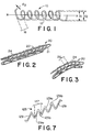
- Figure 1 is a perspective view of a conventional helical coil formed of a single wound wire.
- Figure 2 is a perspective view of the stent of the present invention.
- Figure 3 is a perspective view of the stent of Figure 1 exhibiting longitudinal flexibility.
- Figure 4 is a schematic showing of one wave of the wire forming the stent of Figure 2.
- Figure 5 is a schematic showing of nested longitudinally adjacent waves of the stent of Figure 2.
- Figure 6 is a perspective view of the stent of Figure 2 shown in the open or exposed condition.
- Figure 7 shows a portion of a further embodiment of a wire used to form a stent in accordance with the present invention.
- Figure 8 shows a still further embodiment of a wire used to form a stent of the present invention, partially wound around a forming mandrel.
- Coil spring 10 is formed of a single metallic wire 12 which for stent purposes may be formed of a suitably flexible biocompatible metal.
- the wire coil spring 10 defines generally a cylindrical tubular shape which is radially expandable upon application of outward radial pressure from the interior thereof.
- the spring defines a generally elongate cylindrically tubular shape lying along a central axis ⁇ .
- Wire 12 is helically wound, for example against a constant diameter mandrel (not shown), to form a longitudinally extending structure consisting of wire 12 and spaces or pitch 16 therebetween.
- Each individual winding 14 may be defined as the wire segment traversing one complete revolution around axis ⁇ . As the wire is helically coiled about axis ⁇ , each winding is successively longitudinally spaced from the next adjacent winding by a given distance.
- the axial spacing between any point on the wire coil spring 10 to the point defining the next successive winding may be thought of as the pitch 16 of the wire coil spring 10.
- the pitch of the coil spring 10 defines the spacing between windings and therefore the degree of compactness or compression of the wire coil spring 10.
- wire coil spring 10 has a generally cylindrical tubular shape, it defines an outside diameter d1 and an inside diameter d2 which would typically differ by twice the diameter d3 of wire 12. Further, wire coil spring 10 generally defines an outer cylindrical surface area along its length which may be thought of as being composed of solid surface portions defined by the outward facing surface of wire 12 itself and open surface portions defined by the spaces or pitch 16 multiplied by the number of wire windings 14. The ratio of open surface space to solid surface space may be varied by varying the so-defined pitch 16 of the wire coil spring 10. A smaller pitch coil, where the windings are more compacted or compressed, would result in an outer surface area having less open space than a coil formed to have greater spacing or pitch between the wire windings.
- Wire stent 20 of the present invention is shown in Figure 2.
- Wire stent 20 is generally in the form of an elongate cylindrically shaped tubular member defining a central open passage 21 therethrough.
- Stent 20 is formed of multiple windings 24 of a single wire 22 which in the present invention is metallic, preferably tantalum, as such wire exhibits sufficient spring elasticity for purposes which will be described in further detail hereinbelow.
- stent 20 may be formed by helically winding wire 22 much in a manner shown with respect to Figure 1 to form wire coil spring 10, the present invention contemplates preshaping the wire 22 itself along its length prior to helically coiling the wire.
- wire 22 in an elongate pre-helically coiled configuration may be shaped in a manner having a longitudinally extending wave-like pattern.
- Wave pattern 25 is defined by a plurality of continuously repeating wave lengths 27 therealong. It has been found advantageously that the waves may take the form specifically shown in Figure 4 and 5 for optimum results as a wire stent. However, for explanation purposes, the wave-like pattern 25 generally functions mathematically as sinusoidal wave, having a given amplitude A as measured from a central axis y and a peak-to-peak amplitude of 2A.
- the wave pattern 25 has a uniform preselected period ⁇ equal to the transverse extent of a single wave length.
- the geometry of each wave length 27 is shown in Figure 4.
- the wave-like configuration imparted to wire 22 may be accomplished in a variety of forming techniques.
- One such technique is to pass wire 22 between the teeth of intermeshed gears (not shown) which would place a generally uniform sinusoidal wave-like crimp along the length of the wire.
- Other techniques may be used to form the specific shape shown in Figure 4.
- Wire 22 may be passed through a pair of gear-like overlapping wheels (not shown) having depending interdigitating pins. By arranging the size, position and spacing of the pins, various wave-like configurations may be achieved.
- the particular shape shown with reference to Figures 4 and 5 has been selected as each wave length 27 includes a pair of non-curved linear sections 29 between curved peaks 31. As will be described with respect to Figure 5, this configuration allows the waves to be stacked or nested with maximum compactness when the wire is helically wound around a forming mandrel ( Figure 8) into the shape shown in Figure 2.
- FIG. 5 schematically shown is a portion of stent 20 of Figure 2 which has been cut once, parallel to the ⁇ axis and flattened after being wound in a helical fashion such as that described with respect to the wire coil spring 10 of Figure 1.
- Wire 22 formed in the manner shown and described with respect to Figure 4 may be helically wound around an appropriately shaped mandrel ( Figure 8).
- the width of the mandrel is selected in combination with the frequency and period of the waves forming wire 22 so that upon helical coiling therearound the waves forming each winding 24 are longitudinally stacked or nested within the waves formed by the longitudinally adjacent winding successively spaced therefrom.
- the peaks 31 of the waves of longitudinally adjacent windings 24 are each linearly aligned so that each wave is stacked or nested within the next adjacent wave.
- the spacing or pitch 26 between each longitudinally successive winding 24 is constructed to be minimal.
- nesting or stacking does occur where the pitch or spacing between longitudinally adjacent windings 24 is less than 2A i.e. the peak-to-peak amplitude.
- the pitch or spacing 26 between adjacent windings 24 will be nested within the wave formed by the previously formed winding 24.
- the particular wave-like pattern imparted to wire 22 as shown in Figure 4 allows particularly tight stacking of longitudinally adjacent windings.
- the particular configuration of the stent 20 shown in Figure 2 provides significant advantages in medical applications.
- the stent 20 of the present invention is typically implanted by means of a balloon catheter (not shown).
- the stent 20 in a closed form is held around a deflatable catheter balloon.
- the stent is then inserted into the lumen and located at the desired position.
- the shape of the closed stent shown in Figure 2 permits ease of insertability.
- the stent may be easily bent or flexed along its longitudinal extent.
- the spacing or pitch 26 of windings 24 facilitate such bending.
- the balloon is inflated and the stent is radially expanded for deployment. The balloon is then deflated, and the catheter is removed leaving the expanded stent in place.
- the windings of stent 20 in closed condition are tightly nested.
- the cylindrical surface area formed by the coiled wire has greater wire density, i.e. more of the surface area is composed of solid wire while less of the surface area is composed by open space between the wire windings then in previous non-nested single wire stents.
- the wire surface area in the closed condition equals the wire surface area in an expanded condition.
- the stent 20 of the present invention expands without significant foreshortening of the stent or rotation of the ends of the coil. Rather, expansion is achieved by a flattening or elongation of the individual waves of the stent 20.
- the increased wire surface area as well as the particular shape of the wire provides sufficient radial strength to resist the compressive forces of a blocked, constricted or impinged upon lumen.
- the above-described benefits of the stent of the present invention are achieved without the necessity of longitudinally overlapping adjacent wire windings.
- the stents include portions of wire windings which are longitudinally overlapped. This increases the wall thickness of the stent thereat and results in a stent which is more difficult to implant in the body lumen by means of a balloon catheter. Also, such stents create an undesirable, more turbulent fluid flow therethrough.
- the stent of the present invention maximizes wire density, maintains a high degree of flexibility and radial compressive strength without increasing the stent wall thickness beyond the single wire diameter.
- Each wave length 27 of the wave pattern 25 forming stent 20 is formed to include a straight leg segment 29 with a bend radius at peak 31.
- the angle at which the helix coils around the center line ⁇ ( Figure 1) is assumed to be close to 90°, so that the successive windings 24 are positioned to be as close to concentric as possible while still maintaining a helical pattern.
- N The integer number of waves N per single circumference or single winding follows the equation: N + ⁇ D ⁇ ; where D is the diameter of the closed stent and ⁇ is the period of a single wave.
- the exterior exposed surface area of the stent is equivalent to the amount of wire packed within a fixed stent length.
- the total length L w of wire employed to form the stent follows the equation: where r is the radius defining the peak curvative; and l is the length of the straight line segment 29 of the wire.
- a stent having the parameters listed in Table I and formed in accordance with the present invention yields a percentage of open space (% open) equivalent to 28.959%.
- TABLE I L Length of Stent 1.000 in D Diameter of Closed Stent 0.157 in d3 Wire Diameter 0.010 in r Radius of Curvative of Peak 0.020 in N Number of Waves per Winding 3 M Number of Windings per Stent 22.47 l Length of Straight Portion of Stent 0.097 in
- an expanded stent constructed in accordance with the example set forth above exhibits superior resistance to pressure P acting upon the stent in a radially compressive manner ( Figure 6).
- P has been has been determined, both mathematically and empirically, to be 10 psi.
- the stent of the present invention may be modified in various known manners to provide for increased strength and support.
- the end of wire 22 may be looped around an adjacent wave or extended to run along the length of the stent.
- the wire may be welded to each winding to add structural support such as is shown in U.S. Patent No. 5,133,732.
- each windings may be directly welded to the adjacent winding to form a support spine such as shown in U.S. Patent No. 5,019,090.
- wire 22 is helically wound around a mandrel to form the helical pattern shown in Figure 1. While the angle at which the helix coils around the mandrel is quite small, a certain angle must be imparted to the uniform windings to form a coil. It is further contemplated that a helix-like winding may be formed by concentrically wrapping a wave pattern around the mandrel where the length of the sides of each wave are unequal. As shown in Figure 7 a wave pattern 125 may be formed having leg segments 129 of uneven length. Wave pattern 125 includes individual wave lengths 127 having a first leg segment 129a and a second leg segment 129b. Leg segment 129a is constructed to be shorter than leg segment 129b.
- wave pattern 125 has a step-type shape so that upon winding around a mandrel, the windings 124 coil in a helical-like fashion therearound. This provides a lengthwise extent to the coil without having to impart a helical wrap thereto. Forming the stent length in this manner may tend to result in better flow characteristics through the stent in use.
- Figure 8 shows a wire 222 which has been preformed to have a wave pattern 225 which is generally triangular in shape.
- This wave pattern 225 includes individual wave lengths 227 having straight leg segments 229a and 229b which meet at an apex 231.
- Wire 222 so formed may be wound around a mandrel 200.
- the apices 231 of the wave length 227 are longitudinally aligned.
- the winding of wire 222 around mandrel 200 takes place in the following manner.
- the formed wire 222 is held in position while the mandrel is rotated in the direction of arrow A, thereby coiling the wire 222 around mandrel 200.
- the spacing or pitch 216 is created by subsequent vertical movement of the of the formed wire 222 along mandrel 200 while rotation thereof is taking place.
- the ends 233 of the wire 222 may be "tied off" by looping the end 233 around the next longitudinally adjacent winding.
- the wire could be formed to have waves of varied amplitude.
- the wire could be formed so that at the ends of the wound stent the amplitude of the waves is relatively small while in the central portion of the stent the amplitude is relatively large. This provides a stent with a more flexible central section and more crush-resistant ends.
- the stent of the present invention may include a membrane covering (not shown) which would cover the entire stent.
- the wire surface of the stent would serve as a support surface for the membrane covering.
- the membrane covering would act as a further barrier to tissue ingrowth.
- Any membrane covering may be employed with the present invention such as a fabric or elastic film. Further, this membrane covering may be completely solid or may be porous.
- employing a formed wire having varied amplitude where the amplitude of the wire is smaller at the ends of the stent would help support the membrane covering as the crush-resistant ends would serve as anchors to support the membrane covering with little support necessary at the more flexible central section of the stent.
Landscapes
- Health & Medical Sciences (AREA)
- Engineering & Computer Science (AREA)
- Heart & Thoracic Surgery (AREA)
- Biomedical Technology (AREA)
- General Health & Medical Sciences (AREA)
- Vascular Medicine (AREA)
- Life Sciences & Earth Sciences (AREA)
- Transplantation (AREA)
- Oral & Maxillofacial Surgery (AREA)
- Animal Behavior & Ethology (AREA)
- Cardiology (AREA)
- Public Health (AREA)
- Veterinary Medicine (AREA)
- Mechanical Engineering (AREA)
- Media Introduction/Drainage Providing Device (AREA)
- Prostheses (AREA)
Abstract
Description
- The present invention relates generally to implantable intraluminal stents and more particularly, the present invention relates to an improved high strength intraluminal stent having increased wire density.
- It is well known to employ endoprostheses for the treatment of diseases of various body vessels. Intraluminal devices of this type are commonly referred to as stents. These devices are typically intraluminally implanted by use of a catheter into various body organs such as the vascular system, the bile tract and the urogenital tract. Many of the stents are radially compressible and expandable so that they may be easily inserted through the lumen in a collapsed or unexpanded state. Some stent designs are generally flexible so they can be easily maneuvered through the various body vessels for deployment. Once in position, the stent may be deployed by allowing the stent to expand to its uncompressed state or by expanding the stent by use of a catheter balloon.
- As stents are normally employed to hold open an otherwise blocked, constricted or occluded lumen, a stent must exhibit a relatively high degree of radial or hoop strength in its expanded state. The need for such high strength stents is especially seen in stents used in the urogenital or bile tracts where disease or growth adjacent the lumen may exert an external compressive force thereon which would tend to close the lumen.
- One particular form of stent currently being used is a wire stent. Stents of this type are formed by single or multiple strands of wire which may be formed into a shape such as a mesh coil, helix or the like which is flexible and readily expandable. The spaces between the coiled wire permit such flexibility and expansion. However, in certain situations, such as when the stent is employed in the urogenital or bile tract, it is also desirable to inhibit tissue ingrowth through the stent. Such ingrowth through the stent could have a tendency to reclose or occlude the open lumen. The open spaces between the wires forming the stent, while facilitating flexibility and expansion, have a tendency to allow such undesirable tissue ingrowth.
- Attempts have been made to provide a stent which has less open space and more solid wire. U.S. Patent No. 5,133,732 shows a wire stent where the wire forming the stent is overlapped during formation to provide less open space. However such overlapping wire increases the diameter of the stent and has a tendency to reduce flexibility and make implantation more difficult. It is therefore desirable to provide a wire stent which exhibits high compressive strength and full flexibility without allowing extensive ingrowth therethrough.
- It is an object of the present invention to provide an intraluminal stent which exhibits high compressive strength and is resistive to tissue ingrowth.
- It is a further object of the present invention to provide a flexible wire stent having high compressive strength and maximum wire density to inhibit tissue ingrowth.
- In the efficient attainment of these and other objects, the present invention provides an intraluminal stent including a generally elongate tubular body formed of a wound wire. The wire forming the stent is formed into successively shaped waves, the waves being helically wound along the length of the tube. The longitudinal spacing between the helical windings of the tube is formed to be less than twice the amplitude of the waves thereby resulting in a dense wire configuration.
- As more particularly shown by way of the preferred embodiment herein, an intraluminal wire stent includes longitudinally adjacent waves being nested along the length of the tubular body. The peaks or apices of the longitudinally nested waves are linerally aligned. Further, the intraluminal stent so constructed would have a percentage of open surface area in relationship to the total surface area of the stent which is less than 30% in the closed state, resulting in less open area upon expansion which would inhibit tissue ingrowth.
- Figure 1 is a perspective view of a conventional helical coil formed of a single wound wire.
- Figure 2 is a perspective view of the stent of the present invention.
- Figure 3 is a perspective view of the stent of Figure 1 exhibiting longitudinal flexibility.
- Figure 4 is a schematic showing of one wave of the wire forming the stent of Figure 2.
- Figure 5 is a schematic showing of nested longitudinally adjacent waves of the stent of Figure 2.
- Figure 6 is a perspective view of the stent of Figure 2 shown in the open or exposed condition.
- Figure 7 shows a portion of a further embodiment of a wire used to form a stent in accordance with the present invention.
- Figure 8 shows a still further embodiment of a wire used to form a stent of the present invention, partially wound around a forming mandrel.
- A simple helically formed
coil spring 10 is shown in Figure 1.Coil spring 10 is formed of a singlemetallic wire 12 which for stent purposes may be formed of a suitably flexible biocompatible metal. Thewire coil spring 10 defines generally a cylindrical tubular shape which is radially expandable upon application of outward radial pressure from the interior thereof. - The present invention shown in Figure 2, improves upon the
simple coil spring 10 shown in Figure 1. However with reference to Figure 1, certain terminology used hereinthroughout may be defined. As mentioned, the spring defines a generally elongate cylindrically tubular shape lying along a central axis χ.Wire 12 is helically wound, for example against a constant diameter mandrel (not shown), to form a longitudinally extending structure consisting ofwire 12 and spaces orpitch 16 therebetween. Each individual winding 14 may be defined as the wire segment traversing one complete revolution around axis χ. As the wire is helically coiled about axis χ, each winding is successively longitudinally spaced from the next adjacent winding by a given distance. - For present purposes, the axial spacing between any point on the
wire coil spring 10 to the point defining the next successive winding may be thought of as thepitch 16 of thewire coil spring 10. As so defined, the pitch of thecoil spring 10 defines the spacing between windings and therefore the degree of compactness or compression of thewire coil spring 10. - Also with reference to Figure 1, as the
wire coil spring 10 has a generally cylindrical tubular shape, it defines an outside diameter d₁ and an inside diameter d₂ which would typically differ by twice the diameter d₃ ofwire 12. Further,wire coil spring 10 generally defines an outer cylindrical surface area along its length which may be thought of as being composed of solid surface portions defined by the outward facing surface ofwire 12 itself and open surface portions defined by the spaces orpitch 16 multiplied by the number of wire windings 14. The ratio of open surface space to solid surface space may be varied by varying the so-defined pitch 16 of thewire coil spring 10. A smaller pitch coil, where the windings are more compacted or compressed, would result in an outer surface area having less open space than a coil formed to have greater spacing or pitch between the wire windings. - Having set forth the definitional convention used hereinthroughout, the present invention may be described with reference specifically to Figures 2-6. A
wire stent 20 of the present invention is shown in Figure 2.Wire stent 20 is generally in the form of an elongate cylindrically shaped tubular member defining a centralopen passage 21 therethrough.Stent 20 is formed ofmultiple windings 24 of asingle wire 22 which in the present invention is metallic, preferably tantalum, as such wire exhibits sufficient spring elasticity for purposes which will be described in further detail hereinbelow. - While
stent 20 may be formed by helically windingwire 22 much in a manner shown with respect to Figure 1 to formwire coil spring 10, the present invention contemplates preshaping thewire 22 itself along its length prior to helically coiling the wire. - Referring now to Figure 4,
wire 22 in an elongate pre-helically coiled configuration may be shaped in a manner having a longitudinally extending wave-like pattern.Wave pattern 25 is defined by a plurality of continuously repeatingwave lengths 27 therealong. It has been found advantageously that the waves may take the form specifically shown in Figure 4 and 5 for optimum results as a wire stent. However, for explanation purposes, the wave-like pattern 25 generally functions mathematically as sinusoidal wave, having a given amplitude A as measured from a central axis y and a peak-to-peak amplitude of 2A. Thewave pattern 25 has a uniform preselected period λ equal to the transverse extent of a single wave length. The geometry of eachwave length 27 is shown in Figure 4. - The wave-like configuration imparted to wire 22 may be accomplished in a variety of forming techniques. One such technique is to pass
wire 22 between the teeth of intermeshed gears (not shown) which would place a generally uniform sinusoidal wave-like crimp along the length of the wire. Other techniques may be used to form the specific shape shown in Figure 4.Wire 22 may be passed through a pair of gear-like overlapping wheels (not shown) having depending interdigitating pins. By arranging the size, position and spacing of the pins, various wave-like configurations may be achieved. The particular shape shown with reference to Figures 4 and 5 has been selected as eachwave length 27 includes a pair of non-curvedlinear sections 29 betweencurved peaks 31. As will be described with respect to Figure 5, this configuration allows the waves to be stacked or nested with maximum compactness when the wire is helically wound around a forming mandrel (Figure 8) into the shape shown in Figure 2. - Referring now to Figure 5, schematically shown is a portion of
stent 20 of Figure 2 which has been cut once, parallel to the χ axis and flattened after being wound in a helical fashion such as that described with respect to thewire coil spring 10 of Figure 1.Wire 22 formed in the manner shown and described with respect to Figure 4, may be helically wound around an appropriately shaped mandrel (Figure 8). The width of the mandrel is selected in combination with the frequency and period of thewaves forming wire 22 so that upon helical coiling therearound the waves forming each winding 24 are longitudinally stacked or nested within the waves formed by the longitudinally adjacent winding successively spaced therefrom. - As can be seen with respect to Figure 5, the
peaks 31 of the waves of longitudinallyadjacent windings 24 are each linearly aligned so that each wave is stacked or nested within the next adjacent wave. In optimum configuration, the spacing or pitch 26 between each longitudinally successive winding 24 is constructed to be minimal. However, nesting or stacking does occur where the pitch or spacing between longitudinallyadjacent windings 24 is less than 2A i.e. the peak-to-peak amplitude. As long as the pitch remains less than 2A each longitudinally adjacent winding 24 will be nested within the wave formed by the previously formed winding 24. By minimizing the pitch or spacing 26 betweenadjacent windings 24, the open space between windings may be minimized. The particular wave-like pattern imparted to wire 22 as shown in Figure 4 allows particularly tight stacking of longitudinally adjacent windings. - The particular configuration of the
stent 20 shown in Figure 2, provides significant advantages in medical applications. Thestent 20 of the present invention is typically implanted by means of a balloon catheter (not shown). Thestent 20 in a closed form is held around a deflatable catheter balloon. The stent is then inserted into the lumen and located at the desired position. The shape of the closed stent shown in Figure 2 permits ease of insertability. As shown in Figure 3, the stent may be easily bent or flexed along its longitudinal extent. The spacing or pitch 26 ofwindings 24 facilitate such bending. This helps in the insertion and deployment of the stent through a lumen, as typically body lumens traverse a torturous path through the body which must be followed by the stent which is being deployed therein. Once properly located, the balloon is inflated and the stent is radially expanded for deployment. The balloon is then deflated, and the catheter is removed leaving the expanded stent in place. - The windings of
stent 20 in closed condition are tightly nested. The cylindrical surface area formed by the coiled wire has greater wire density, i.e. more of the surface area is composed of solid wire while less of the surface area is composed by open space between the wire windings then in previous non-nested single wire stents. The wire surface area in the closed condition equals the wire surface area in an expanded condition. By maximizing the closed condition wire surface area, even when the stent is expanded such as shown in Figure 6, the expanded wire surface area is also maximized reducing tissue ingrowth between the expanded windings of the stent. Contrary to a simple coil spring such as that shown in Figure 1, thestent 20 of the present invention expands without significant foreshortening of the stent or rotation of the ends of the coil. Rather, expansion is achieved by a flattening or elongation of the individual waves of thestent 20. Once the stent is expanded after deployment to a shape shown in Figure 6, the increased wire surface area as well as the particular shape of the wire provides sufficient radial strength to resist the compressive forces of a blocked, constricted or impinged upon lumen. - Additionally, the above-described benefits of the stent of the present invention are achieved without the necessity of longitudinally overlapping adjacent wire windings. In many prior art stents, the stents include portions of wire windings which are longitudinally overlapped. This increases the wall thickness of the stent thereat and results in a stent which is more difficult to implant in the body lumen by means of a balloon catheter. Also, such stents create an undesirable, more turbulent fluid flow therethrough. The stent of the present invention maximizes wire density, maintains a high degree of flexibility and radial compressive strength without increasing the stent wall thickness beyond the single wire diameter.
- Mathematically, the geometric analysis of the preferred embodiment of the stent of the present invention may be described as follows with reference to Figures 4 and 5.
- Each
wave length 27 of thewave pattern 25 formingstent 20 is formed to include astraight leg segment 29 with a bend radius atpeak 31. The angle at which the helix coils around the center line χ (Figure 1) is assumed to be close to 90°, so that thesuccessive windings 24 are positioned to be as close to concentric as possible while still maintaining a helical pattern. - The integer number of waves N per single circumference or single winding follows the equation:

where D is the diameter of the closed stent and λ is the period of a single wave. - The number of helical windings M per stent is defined by the equation:

where L is the overall stent length; θ is the angle of thestraight leg segments 29 with respect the line of amplitude of the wave pattern; and d₃ is the wire diameter. - The exterior exposed surface area of the stent is equivalent to the amount of wire packed within a fixed stent length. The total length Lw of wire employed to form the stent follows the equation:

where r is the radius defining the peak curvative; and ℓ is the length of thestraight line segment 29 of the wire. - It follows that the projected solid wire area is Lwd₃ and the percentage of open space coverage (% open) is given by the equation:

- In a specific example, a stent having the parameters listed in Table I and formed in accordance with the present invention yields a percentage of open space (% open) equivalent to 28.959%.
TABLE I L Length of Stent 1.000 in D Diameter of Closed Stent 0.157 in d₃ Wire Diameter 0.010 in r Radius of Curvative of Peak 0.020 in N Number of Waves per Winding 3 M Number of Windings per Stent 22.47 ℓ Length of Straight Portion of Stent 0.097 in - Further, it is found that an expanded stent constructed in accordance with the example set forth above, exhibits superior resistance to pressure P acting upon the stent in a radially compressive manner (Figure 6). In the present and illustrative example, P has been has been determined, both mathematically and empirically, to be 10 psi.
- It is further contemplated that the stent of the present invention may be modified in various known manners to provide for increased strength and support. For example the end of
wire 22 may be looped around an adjacent wave or extended to run along the length of the stent. The wire may be welded to each winding to add structural support such as is shown in U.S. Patent No. 5,133,732. Also, each windings may be directly welded to the adjacent winding to form a support spine such as shown in U.S. Patent No. 5,019,090. - Further, as mentioned above,
wire 22 is helically wound around a mandrel to form the helical pattern shown in Figure 1. While the angle at which the helix coils around the mandrel is quite small, a certain angle must be imparted to the uniform windings to form a coil. It is further contemplated that a helix-like winding may be formed by concentrically wrapping a wave pattern around the mandrel where the length of the sides of each wave are unequal. As shown in Figure 7 awave pattern 125 may be formed havingleg segments 129 of uneven length.Wave pattern 125 includesindividual wave lengths 127 having afirst leg segment 129a and asecond leg segment 129b.Leg segment 129a is constructed to be shorter thanleg segment 129b. Thuswave pattern 125 has a step-type shape so that upon winding around a mandrel, the windings 124 coil in a helical-like fashion therearound. This provides a lengthwise extent to the coil without having to impart a helical wrap thereto. Forming the stent length in this manner may tend to result in better flow characteristics through the stent in use. - Other modifications which are within the contemplation of the present invention may be further described. Figure 8 shows a
wire 222 which has been preformed to have awave pattern 225 which is generally triangular in shape. Thiswave pattern 225 includesindividual wave lengths 227 havingstraight leg segments Wire 222 so formed, may be wound around amandrel 200. As theindividual wave lengths 227 nest in a manner above described, theapices 231 of thewave length 227 are longitudinally aligned. - The winding of
wire 222 aroundmandrel 200 takes place in the following manner. The formedwire 222 is held in position while the mandrel is rotated in the direction of arrow A, thereby coiling thewire 222 aroundmandrel 200. The spacing or pitch 216 is created by subsequent vertical movement of the of the formedwire 222 alongmandrel 200 while rotation thereof is taking place. When the winding is complete, theends 233 of thewire 222 may be "tied off" by looping theend 233 around the next longitudinally adjacent winding. - While in the embodiment shown above, the amplitude of each wave is relatively uniform, it is contemplated that the wire could be formed to have waves of varied amplitude. For example, the wire could be formed so that at the ends of the wound stent the amplitude of the waves is relatively small while in the central portion of the stent the amplitude is relatively large. This provides a stent with a more flexible central section and more crush-resistant ends.
- In certain situations the stent of the present invention may include a membrane covering (not shown) which would cover the entire stent. The wire surface of the stent would serve as a support surface for the membrane covering. The membrane covering would act as a further barrier to tissue ingrowth. Any membrane covering may be employed with the present invention such as a fabric or elastic film. Further, this membrane covering may be completely solid or may be porous. In addition, as above described, employing a formed wire having varied amplitude where the amplitude of the wire is smaller at the ends of the stent would help support the membrane covering as the crush-resistant ends would serve as anchors to support the membrane covering with little support necessary at the more flexible central section of the stent.
- Various changes to the foregoing described and shown structures would not be evident to those skilled in the art. Accordingly, the particularly disclosed scope of the invention is set forth in the following claims.
Claims (10)
- An intraluminal stent comprising:
a generally elongate tubular body formed of an elongate helically wound wire, the wire being formed into successive waves along the length of the wire, the waves being arranged in non-overlapping longitudinally spaced succession along the length of said tube, the longitudinal spacing of the helical windings being less than twice the amplitude of the wave. - An intraluminal stent according to claim 1, wherein longitudinally adjacent ones of the waves are longitudinally nested along the length of the tubular body.
- An intraluminal stent according to claim 2, wherein the longitudinally nested waves define peaks which are linearly aligned.
- An intraluminal stent according to any preceding claim, wherein the longitudinal spacing of the helical windings is less than the amplitude of the wave.
- An intraluminal stent according to any preceding claim, wherein the wire is helically wound in non-overlapping disposition, wherein the wire defines an open area between the helically wound wire, and wherein the percentage of open surface area of the stent in relation to the total surface area of the stent is less than 30% in the closed condition.
- A radially expandable generally tubular endoluminal implantable prosthesis, comprising:
a wire which is wound in a helical configuration to define a generally elongate tubular body, the wire including successively formed waves along the length of the wire, each wire wave being non-overlappingly nested within the wave formed longitudinally thereadjacent. - A prosthesis according to claim 6, wherein the wire waves are of generally uniform configuration defining a peak-to-peak amplitude of a preselected first dimension.
- A prosthesis according to claim 7, wherein the longitudinally adjacent wire waves are spaced apart a preselected second dimension which is less than the preselected first dimension.
- A prosthesis according to claim 6, 7 or 8, wherein the wire has a given wire diameter and wherein the wound wire defines a generally cylindrical outer surface having solid portions formed by the wire and open portions formed between the wound wire.
- A prosthesis according to claim 9, wherein the generally cylindrical outer surface defines a total surface area including an open surface and a wire and wherein the non-expanded wire surface substantially exceeds the open surface.
Priority Applications (1)
| Application Number | Priority Date | Filing Date | Title |
|---|---|---|---|
| EP03016540A EP1360943A3 (en) | 1994-08-12 | 1995-04-27 | High stength and high density intraluminal wire stent |
Applications Claiming Priority (2)
| Application Number | Priority Date | Filing Date | Title |
|---|---|---|---|
| US08/289,791 US5575816A (en) | 1994-08-12 | 1994-08-12 | High strength and high density intraluminal wire stent |
| US289791 | 1994-08-12 |
Related Child Applications (1)
| Application Number | Title | Priority Date | Filing Date |
|---|---|---|---|
| EP03016540A Division EP1360943A3 (en) | 1994-08-12 | 1995-04-27 | High stength and high density intraluminal wire stent |
Publications (2)
| Publication Number | Publication Date |
|---|---|
| EP0705577A1 true EP0705577A1 (en) | 1996-04-10 |
| EP0705577B1 EP0705577B1 (en) | 2004-02-18 |
Family
ID=23113118
Family Applications (2)
| Application Number | Title | Priority Date | Filing Date |
|---|---|---|---|
| EP95302879A Expired - Lifetime EP0705577B1 (en) | 1994-08-12 | 1995-04-27 | Nested Stent |
| EP03016540A Withdrawn EP1360943A3 (en) | 1994-08-12 | 1995-04-27 | High stength and high density intraluminal wire stent |
Family Applications After (1)
| Application Number | Title | Priority Date | Filing Date |
|---|---|---|---|
| EP03016540A Withdrawn EP1360943A3 (en) | 1994-08-12 | 1995-04-27 | High stength and high density intraluminal wire stent |
Country Status (9)
| Country | Link |
|---|---|
| US (5) | US5575816A (en) |
| EP (2) | EP0705577B1 (en) |
| JP (1) | JPH0857057A (en) |
| AU (1) | AU699485B2 (en) |
| CA (1) | CA2147548C (en) |
| DE (1) | DE69532573T2 (en) |
| DK (1) | DK0705577T3 (en) |
| ES (1) | ES2216003T3 (en) |
| FI (1) | FI952214A (en) |
Cited By (14)
| Publication number | Priority date | Publication date | Assignee | Title |
|---|---|---|---|---|
| EP0750890A1 (en) * | 1995-05-31 | 1997-01-02 | Global Therapeutics Inc. | Radially expandable stent |
| EP0808614A2 (en) * | 1996-05-23 | 1997-11-26 | SAMSUNG ELECTRONICS Co. Ltd. | Flexible self-expandable stent and method for making the same |
| WO1998027893A3 (en) * | 1996-12-23 | 1998-11-12 | Prograft Medical Inc | Kink resistant bifurcated prosthesis |
| FR2771921A1 (en) * | 1997-12-09 | 1999-06-11 | Jean Marie Lefebvre | STAINLESS STEEL STENT TO BE IMPLANTED IN A VASCULAR CONDUIT USING AN INFLATABLE BALLOON |
| EP0778038A3 (en) * | 1995-12-07 | 2000-02-09 | Sarcos, Inc. | Hollow coil guide wire apparatus for catheters |
| US6352553B1 (en) | 1995-12-14 | 2002-03-05 | Gore Enterprise Holdings, Inc. | Stent-graft deployment apparatus and method |
| US6352561B1 (en) | 1996-12-23 | 2002-03-05 | W. L. Gore & Associates | Implant deployment apparatus |
| US6361637B2 (en) | 1995-12-14 | 2002-03-26 | Gore Enterprise Holdings, Inc. | Method of making a kink resistant stent-graft |
| US6517570B1 (en) | 1994-08-31 | 2003-02-11 | Gore Enterprise Holdings, Inc. | Exterior supported self-expanding stent-graft |
| US6613072B2 (en) | 1994-09-08 | 2003-09-02 | Gore Enterprise Holdings, Inc. | Procedures for introducing stents and stent-grafts |
| AU770017B2 (en) * | 1996-12-23 | 2004-02-12 | W.L. Gore & Associates, Inc. | Kink resistant bifurcated prosthesis |
| AU2005200837B2 (en) * | 1996-12-23 | 2006-12-07 | W. L. Gore & Associates, Inc. | Kink resistant bifurcated prosthesis |
| EP1745761A1 (en) * | 2000-08-23 | 2007-01-24 | LeMaitre Acquisition LLC | Method of manufacturing custom intravascular devices |
| AU2007200411B2 (en) * | 1999-01-22 | 2008-05-29 | W. L. Gore & Associates, Inc. | Low profile stent and graft combination |
Families Citing this family (212)
| Publication number | Priority date | Publication date | Assignee | Title |
|---|---|---|---|---|
| RU2089131C1 (en) * | 1993-12-28 | 1997-09-10 | Сергей Апполонович Пульнев | Stent-expander |
| US6165210A (en) | 1994-04-01 | 2000-12-26 | Gore Enterprise Holdings, Inc. | Self-expandable helical intravascular stent and stent-graft |
| US6001123A (en) | 1994-04-01 | 1999-12-14 | Gore Enterprise Holdings Inc. | Folding self-expandable intravascular stent-graft |
| US5575816A (en) * | 1994-08-12 | 1996-11-19 | Meadox Medicals, Inc. | High strength and high density intraluminal wire stent |
| US7204848B1 (en) | 1995-03-01 | 2007-04-17 | Boston Scientific Scimed, Inc. | Longitudinally flexible expandable stent |
| US6261318B1 (en) | 1995-07-25 | 2001-07-17 | Medstent Inc. | Expandable stent |
| HU221910B1 (en) * | 1995-07-25 | 2003-02-28 | Medstent Inc. | Expandible stent |
| US6899728B1 (en) | 1998-01-26 | 2005-05-31 | Bridport (Uk) Limited | Reinforced graft |
| EP0879068A4 (en) * | 1996-02-02 | 1999-04-21 | Transvascular Inc | Methods and apparatus for blocking flow through blood vessels |
| EP0795304B1 (en) * | 1996-03-10 | 2004-05-19 | Terumo Kabushiki Kaisha | Implanting stent |
| US5776183A (en) * | 1996-08-23 | 1998-07-07 | Kanesaka; Nozomu | Expandable stent |
| US5733330A (en) * | 1997-01-13 | 1998-03-31 | Advanced Cardiovascular Systems, Inc. | Balloon-expandable, crush-resistant locking stent |
| US5925061A (en) | 1997-01-13 | 1999-07-20 | Gore Enterprise Holdings, Inc. | Low profile vascular stent |
| US6951572B1 (en) | 1997-02-20 | 2005-10-04 | Endologix, Inc. | Bifurcated vascular graft and method and apparatus for deploying same |
| US5830229A (en) | 1997-03-07 | 1998-11-03 | Micro Therapeutics Inc. | Hoop stent |
| US5810872A (en) | 1997-03-14 | 1998-09-22 | Kanesaka; Nozomu | Flexible stent |
| US6033433A (en) * | 1997-04-25 | 2000-03-07 | Scimed Life Systems, Inc. | Stent configurations including spirals |
| EP0884029B1 (en) * | 1997-06-13 | 2004-12-22 | Gary J. Becker | Expandable intraluminal endoprosthesis |
| US5976182A (en) * | 1997-10-03 | 1999-11-02 | Advanced Cardiovascular Systems, Inc. | Balloon-expandable, crush-resistant locking stent and method of loading the same |
| US20050154446A1 (en) * | 1998-01-26 | 2005-07-14 | Peter Phillips | Reinforced graft |
| US7520890B2 (en) * | 1998-01-26 | 2009-04-21 | Phillips Peter W | Reinforced graft and method of deployment |
| US6623521B2 (en) | 1998-02-17 | 2003-09-23 | Md3, Inc. | Expandable stent with sliding and locking radial elements |
| EP2198813B1 (en) * | 1998-03-05 | 2012-08-29 | Boston Scientific Limited | Intraluminal stent |
| US6171334B1 (en) * | 1998-06-17 | 2001-01-09 | Advanced Cardiovascular Systems, Inc. | Expandable stent and method of use |
| US7235096B1 (en) | 1998-08-25 | 2007-06-26 | Tricardia, Llc | Implantable device for promoting repair of a body lumen |
| AU760819B2 (en) | 1998-09-08 | 2003-05-22 | Kabushikikaisha Igaki Iryo Sekkei | Stent for vessels |
| US6071307A (en) * | 1998-09-30 | 2000-06-06 | Baxter International Inc. | Endoluminal grafts having continuously curvilinear wireforms |
| US6042597A (en) | 1998-10-23 | 2000-03-28 | Scimed Life Systems, Inc. | Helical stent design |
| US8382821B2 (en) | 1998-12-03 | 2013-02-26 | Medinol Ltd. | Helical hybrid stent |
| US20040267349A1 (en) | 2003-06-27 | 2004-12-30 | Kobi Richter | Amorphous metal alloy medical devices |
| US6187036B1 (en) | 1998-12-11 | 2001-02-13 | Endologix, Inc. | Endoluminal vascular prosthesis |
| US6660030B2 (en) | 1998-12-11 | 2003-12-09 | Endologix, Inc. | Bifurcation graft deployment catheter |
| WO2000033769A1 (en) | 1998-12-11 | 2000-06-15 | Endologix, Inc. | Endoluminal vascular prosthesis |
| US6733523B2 (en) | 1998-12-11 | 2004-05-11 | Endologix, Inc. | Implantable vascular graft |
| US6355057B1 (en) | 1999-01-14 | 2002-03-12 | Medtronic, Inc. | Staggered endoluminal stent |
| US8034100B2 (en) | 1999-03-11 | 2011-10-11 | Endologix, Inc. | Graft deployment system |
| US6261316B1 (en) | 1999-03-11 | 2001-07-17 | Endologix, Inc. | Single puncture bifurcation graft deployment system |
| US6364903B2 (en) * | 1999-03-19 | 2002-04-02 | Meadox Medicals, Inc. | Polymer coated stent |
| US6607551B1 (en) | 1999-05-20 | 2003-08-19 | Scimed Life Systems, Inc. | Stent delivery system with nested stabilizer |
| US6652570B2 (en) * | 1999-07-02 | 2003-11-25 | Scimed Life Systems, Inc. | Composite vascular graft |
| US6551351B2 (en) | 1999-07-02 | 2003-04-22 | Scimed Life Systems | Spiral wound stent |
| US6554857B1 (en) * | 1999-07-20 | 2003-04-29 | Medtronic, Inc | Transmural concentric multilayer ingrowth matrix within well-defined porosity |
| US6402779B1 (en) | 1999-07-26 | 2002-06-11 | Endomed, Inc. | Balloon-assisted intraluminal stent graft |
| US20010018609A1 (en) | 1999-08-11 | 2001-08-30 | Scott Smith | Seamless braided or spun stent cover |
| EP1767169B1 (en) | 1999-09-01 | 2009-03-04 | Boston Scientific Scimed, Inc. | Tubular stent-graft composite device and method of manufacture |
| US6183481B1 (en) | 1999-09-22 | 2001-02-06 | Endomed Inc. | Delivery system for self-expanding stents and grafts |
| PT1230649E (en) * | 1999-11-11 | 2003-10-31 | Reichwein Dietrich | COIL |
| US6221080B1 (en) | 1999-12-10 | 2001-04-24 | John A. Power | Bifurcation lesion stenting catheter |
| US6210431B1 (en) | 1999-12-10 | 2001-04-03 | John A. Power | Ostial bifurcation lesion stenting catheter |
| US6312458B1 (en) | 2000-01-19 | 2001-11-06 | Scimed Life Systems, Inc. | Tubular structure/stent/stent securement member |
| US6210433B1 (en) * | 2000-03-17 | 2001-04-03 | LARRé JORGE CASADO | Stent for treatment of lesions of bifurcated vessels |
| US7722663B1 (en) * | 2000-04-24 | 2010-05-25 | Scimed Life Systems, Inc. | Anatomically correct endoluminal prostheses |
| US6805704B1 (en) | 2000-06-26 | 2004-10-19 | C. R. Bard, Inc. | Intraluminal stents |
| US6613077B2 (en) * | 2001-03-27 | 2003-09-02 | Scimed Life Systems, Inc. | Stent with controlled expansion |
| US6585753B2 (en) * | 2001-03-28 | 2003-07-01 | Scimed Life Systems, Inc. | Expandable coil stent |
| EP1258230A3 (en) | 2001-03-29 | 2003-12-10 | CardioSafe Ltd | Balloon catheter device |
| US7717708B2 (en) * | 2001-04-13 | 2010-05-18 | Orametrix, Inc. | Method and system for integrated orthodontic treatment planning using unified workstation |
| GB0121980D0 (en) | 2001-09-11 | 2001-10-31 | Cathnet Science Holding As | Expandable stent |
| US20040111108A1 (en) | 2001-11-09 | 2004-06-10 | Farnan Robert C. | Balloon catheter with non-deployable stent |
| AU2002348180A1 (en) | 2001-11-09 | 2003-05-26 | Novoste Corporation | Baloon catheter with non-deployable stent |
| US7309350B2 (en) | 2001-12-03 | 2007-12-18 | Xtent, Inc. | Apparatus and methods for deployment of vascular prostheses |
| US7137993B2 (en) | 2001-12-03 | 2006-11-21 | Xtent, Inc. | Apparatus and methods for delivery of multiple distributed stents |
| US8080048B2 (en) | 2001-12-03 | 2011-12-20 | Xtent, Inc. | Stent delivery for bifurcated vessels |
| US7147656B2 (en) | 2001-12-03 | 2006-12-12 | Xtent, Inc. | Apparatus and methods for delivery of braided prostheses |
| US20040186551A1 (en) | 2003-01-17 | 2004-09-23 | Xtent, Inc. | Multiple independent nested stent structures and methods for their preparation and deployment |
| US20030135266A1 (en) | 2001-12-03 | 2003-07-17 | Xtent, Inc. | Apparatus and methods for delivery of multiple distributed stents |
| US7892273B2 (en) | 2001-12-03 | 2011-02-22 | Xtent, Inc. | Custom length stent apparatus |
| US7182779B2 (en) | 2001-12-03 | 2007-02-27 | Xtent, Inc. | Apparatus and methods for positioning prostheses for deployment from a catheter |
| US7351255B2 (en) | 2001-12-03 | 2008-04-01 | Xtent, Inc. | Stent delivery apparatus and method |
| US7294146B2 (en) | 2001-12-03 | 2007-11-13 | Xtent, Inc. | Apparatus and methods for delivery of variable length stents |
| US20030225439A1 (en) * | 2002-05-31 | 2003-12-04 | Cook Alonzo D. | Implantable product with improved aqueous interface characteristics and method for making and using same |
| US11890181B2 (en) | 2002-07-22 | 2024-02-06 | Tmt Systems, Inc. | Percutaneous endovascular apparatus for repair of aneurysms and arterial blockages |
| US20050033405A1 (en) * | 2002-08-15 | 2005-02-10 | Gmp/Cardiac Care, Inc. | Rail stent-graft for repairing abdominal aortic aneurysm |
| MXPA05001845A (en) | 2002-08-15 | 2005-11-17 | Gmp Cardiac Care Inc | Stent-graft with rails. |
| US9561123B2 (en) | 2002-08-30 | 2017-02-07 | C.R. Bard, Inc. | Highly flexible stent and method of manufacture |
| WO2008100783A2 (en) | 2007-02-12 | 2008-08-21 | C.R. Bard Inc. | Highly flexible stent and method of manufacture |
| US6878162B2 (en) * | 2002-08-30 | 2005-04-12 | Edwards Lifesciences Ag | Helical stent having improved flexibility and expandability |
| US6951053B2 (en) * | 2002-09-04 | 2005-10-04 | Reva Medical, Inc. | Method of manufacturing a prosthesis |
| US8524148B2 (en) * | 2002-11-07 | 2013-09-03 | Abbott Laboratories | Method of integrating therapeutic agent into a bioerodible medical device |
| US8221495B2 (en) | 2002-11-07 | 2012-07-17 | Abbott Laboratories | Integration of therapeutic agent into a bioerodible medical device |
| DE60333028D1 (en) * | 2002-11-07 | 2010-07-29 | Abbott Lab | PROSTHESIS WITH SEVERAL, DISCRETE, UNMIXED MEDICINE DROPS |
| US7901448B2 (en) * | 2002-12-24 | 2011-03-08 | Novostent Corporation | Vascular prothesis having interdigitating edges and methods of use |
| US20050033410A1 (en) | 2002-12-24 | 2005-02-10 | Novostent Corporation | Vascular prothesis having flexible configuration |
| US6896697B1 (en) * | 2002-12-30 | 2005-05-24 | Advanced Cardiovascular Systems, Inc. | Intravascular stent |
| US8080026B2 (en) | 2003-01-21 | 2011-12-20 | Angioscore, Inc. | Apparatus and methods for treating hardened vascular lesions |
| US20040193141A1 (en) * | 2003-02-14 | 2004-09-30 | Leopold Eric W. | Intravascular flow modifier and reinforcement device and deployment system for same |
| US7241308B2 (en) | 2003-06-09 | 2007-07-10 | Xtent, Inc. | Stent deployment systems and methods |
| US9155639B2 (en) * | 2009-04-22 | 2015-10-13 | Medinol Ltd. | Helical hybrid stent |
| US9039755B2 (en) * | 2003-06-27 | 2015-05-26 | Medinol Ltd. | Helical hybrid stent |
| US9861346B2 (en) | 2003-07-14 | 2018-01-09 | W. L. Gore & Associates, Inc. | Patent foramen ovale (PFO) closure device with linearly elongating petals |
| US8500792B2 (en) | 2003-09-03 | 2013-08-06 | Bolton Medical, Inc. | Dual capture device for stent graft delivery system and method for capturing a stent graft |
| US11259945B2 (en) | 2003-09-03 | 2022-03-01 | Bolton Medical, Inc. | Dual capture device for stent graft delivery system and method for capturing a stent graft |
| US20080264102A1 (en) | 2004-02-23 | 2008-10-30 | Bolton Medical, Inc. | Sheath Capture Device for Stent Graft Delivery System and Method for Operating Same |
| US9198786B2 (en) | 2003-09-03 | 2015-12-01 | Bolton Medical, Inc. | Lumen repair device with capture structure |
| US20070198078A1 (en) | 2003-09-03 | 2007-08-23 | Bolton Medical, Inc. | Delivery system and method for self-centering a Proximal end of a stent graft |
| US8292943B2 (en) | 2003-09-03 | 2012-10-23 | Bolton Medical, Inc. | Stent graft with longitudinal support member |
| US11596537B2 (en) | 2003-09-03 | 2023-03-07 | Bolton Medical, Inc. | Delivery system and method for self-centering a proximal end of a stent graft |
| US7763063B2 (en) | 2003-09-03 | 2010-07-27 | Bolton Medical, Inc. | Self-aligning stent graft delivery system, kit, and method |
| US7403966B2 (en) * | 2003-12-08 | 2008-07-22 | Freescale Semiconductor, Inc. | Hardware for performing an arithmetic function |
| US7326236B2 (en) | 2003-12-23 | 2008-02-05 | Xtent, Inc. | Devices and methods for controlling and indicating the length of an interventional element |
| US7497872B2 (en) * | 2004-03-08 | 2009-03-03 | Cook Incorporated | Retainer for a stent-graft |
| US7323006B2 (en) | 2004-03-30 | 2008-01-29 | Xtent, Inc. | Rapid exchange interventional devices and methods |
| US20050288766A1 (en) | 2004-06-28 | 2005-12-29 | Xtent, Inc. | Devices and methods for controlling expandable prostheses during deployment |
| US8317859B2 (en) | 2004-06-28 | 2012-11-27 | J.W. Medical Systems Ltd. | Devices and methods for controlling expandable prostheses during deployment |
| US7763065B2 (en) | 2004-07-21 | 2010-07-27 | Reva Medical, Inc. | Balloon expandable crush-recoverable stent device |
| EP1789030A2 (en) | 2004-08-30 | 2007-05-30 | Interstitial Therapeutics | Medical implant provided with inhibitors of atp synthesis |
| US7780721B2 (en) | 2004-09-01 | 2010-08-24 | C. R. Bard, Inc. | Stent and method for manufacturing the stent |
| US8292944B2 (en) | 2004-12-17 | 2012-10-23 | Reva Medical, Inc. | Slide-and-lock stent |
| JP2006271901A (en) * | 2005-03-30 | 2006-10-12 | Nippon Zeon Co Ltd | Coiled contrast marker, its manufacturing method and catheter |
| US10076641B2 (en) | 2005-05-11 | 2018-09-18 | The Spectranetics Corporation | Methods and systems for delivering substances into luminal walls |
| US7938851B2 (en) | 2005-06-08 | 2011-05-10 | Xtent, Inc. | Devices and methods for operating and controlling interventional apparatus |
| US20060282149A1 (en) | 2005-06-08 | 2006-12-14 | Xtent, Inc., A Delaware Corporation | Apparatus and methods for deployment of multiple custom-length prostheses (II) |
| US7637939B2 (en) * | 2005-06-30 | 2009-12-29 | Boston Scientific Scimed, Inc. | Hybrid stent |
| US7815674B1 (en) | 2005-07-27 | 2010-10-19 | Ragazzo John R | Self-expanding stent system |
| US7914574B2 (en) | 2005-08-02 | 2011-03-29 | Reva Medical, Inc. | Axially nested slide and lock expandable device |
| US9149378B2 (en) | 2005-08-02 | 2015-10-06 | Reva Medical, Inc. | Axially nested slide and lock expandable device |
| US7867176B2 (en) * | 2005-12-27 | 2011-01-11 | Cordis Corporation | Variable stiffness guidewire |
| EP1965732B1 (en) * | 2005-12-29 | 2010-05-05 | Med Institute, Inc. | Endoluminal device including a mechanism for proximal or distal fixation, and sealing and methods of use thereof |
| CA2640234C (en) | 2006-02-14 | 2017-01-03 | Angiomed Gmbh & Co. Medizintechnik Kg | Highly flexible stent and method of manufacture |
| EP1998716A4 (en) | 2006-03-20 | 2010-01-20 | Xtent Inc | Apparatus and methods for deployment of linked prosthetic segments |
| US7785317B2 (en) | 2006-03-29 | 2010-08-31 | Codman & Shurtleff, Inc. | Joined metal tubing and method of manufacture |
| US8118859B2 (en) * | 2006-05-26 | 2012-02-21 | Codman & Shurtleff, Inc. | Occlusion device combination of stent and mesh having offset parallelogram porosity |
| US8690938B2 (en) * | 2006-05-26 | 2014-04-08 | DePuy Synthes Products, LLC | Occlusion device combination of stent and mesh with diamond-shaped porosity |
| US9259336B2 (en) * | 2006-06-06 | 2016-02-16 | Cook Medical Technologies Llc | Stent with a crush-resistant zone |
| US7670353B2 (en) * | 2006-06-12 | 2010-03-02 | Codman & Shurtleff, Inc. | Modified headpiece for hydraulic coil deployment system |
| US7766935B2 (en) * | 2006-06-12 | 2010-08-03 | Codman & Shurtleff, Inc. | Modified headpiece for hydraulic coil deployment system |
| US8585732B2 (en) * | 2006-06-14 | 2013-11-19 | DePuy Synthes Products, LLC | Retrieval device with sidewall grippers |
| WO2008027188A2 (en) * | 2006-08-29 | 2008-03-06 | C. R. Bard, Inc. | Helical high fatigue stent-graft |
| GB0621048D0 (en) * | 2006-10-23 | 2006-11-29 | Anson Medical Ltd | Helical stent graft |
| US9622888B2 (en) | 2006-11-16 | 2017-04-18 | W. L. Gore & Associates, Inc. | Stent having flexibly connected adjacent stent elements |
| US10188534B2 (en) * | 2006-11-17 | 2019-01-29 | Covidien Lp | Stent having reduced passage of emboli and stent delivery system |
| US8523931B2 (en) | 2007-01-12 | 2013-09-03 | Endologix, Inc. | Dual concentric guidewire and methods of bifurcated graft deployment |
| US8388679B2 (en) | 2007-01-19 | 2013-03-05 | Maquet Cardiovascular Llc | Single continuous piece prosthetic tubular aortic conduit and method for manufacturing the same |
| US7704275B2 (en) | 2007-01-26 | 2010-04-27 | Reva Medical, Inc. | Circumferentially nested expandable device |
| EP4005537A1 (en) | 2007-02-12 | 2022-06-01 | C.R. Bard Inc. | Highly flexible stent and method of manufacture |
| US8333799B2 (en) * | 2007-02-12 | 2012-12-18 | C. R. Bard, Inc. | Highly flexible stent and method of manufacture |
| US20080199510A1 (en) | 2007-02-20 | 2008-08-21 | Xtent, Inc. | Thermo-mechanically controlled implants and methods of use |
| US8486132B2 (en) | 2007-03-22 | 2013-07-16 | J.W. Medical Systems Ltd. | Devices and methods for controlling expandable prostheses during deployment |
| WO2008124603A1 (en) | 2007-04-05 | 2008-10-16 | Nmt Medical, Inc. | Septal closure device with centering mechanism |
| AU2007361843B2 (en) | 2007-11-30 | 2013-07-04 | Reva Medical, Inc. | Axially-radially nested expandable device |
| US8574284B2 (en) * | 2007-12-26 | 2013-11-05 | Cook Medical Technologies Llc | Low profile non-symmetrical bare alignment stents with graft |
| US9226813B2 (en) | 2007-12-26 | 2016-01-05 | Cook Medical Technologies Llc | Low profile non-symmetrical stent |
| GB2476451A (en) | 2009-11-19 | 2011-06-29 | Cook William Europ | Stent Graft |
| US9180030B2 (en) | 2007-12-26 | 2015-11-10 | Cook Medical Technologies Llc | Low profile non-symmetrical stent |
| US8926688B2 (en) | 2008-01-11 | 2015-01-06 | W. L. Gore & Assoc. Inc. | Stent having adjacent elements connected by flexible webs |
| CA2781407A1 (en) | 2008-01-14 | 2009-07-23 | Michael P. Brenzel | Apparatus and methods for fracture repair |
| WO2009105699A1 (en) | 2008-02-22 | 2009-08-27 | Endologix, Inc. | Design and method of placement of a graft or graft system |
| US9101503B2 (en) | 2008-03-06 | 2015-08-11 | J.W. Medical Systems Ltd. | Apparatus having variable strut length and methods of use |
| US20130165967A1 (en) | 2008-03-07 | 2013-06-27 | W.L. Gore & Associates, Inc. | Heart occlusion devices |
| US8236040B2 (en) | 2008-04-11 | 2012-08-07 | Endologix, Inc. | Bifurcated graft deployment systems and methods |
| EP3219292B1 (en) * | 2008-06-30 | 2019-08-14 | Bolton Medical Inc. | Abdominal aortic aneurysms systems |
| WO2010002931A1 (en) | 2008-07-01 | 2010-01-07 | Endologix, Inc. | Catheter system |
| US8821562B2 (en) | 2008-09-25 | 2014-09-02 | Advanced Bifurcation Systems, Inc. | Partially crimped stent |
| US8828071B2 (en) | 2008-09-25 | 2014-09-09 | Advanced Bifurcation Systems, Inc. | Methods and systems for ostial stenting of a bifurcation |
| EP2344068B1 (en) | 2008-09-25 | 2022-10-19 | Advanced Bifurcation Systems Inc. | Partially crimped stent |
| US11298252B2 (en) | 2008-09-25 | 2022-04-12 | Advanced Bifurcation Systems Inc. | Stent alignment during treatment of a bifurcation |
| WO2010042854A1 (en) * | 2008-10-10 | 2010-04-15 | Orbusneich Medical, Inc. | Bioabsorbable polymeric medical device |
| EP2331014B1 (en) | 2008-10-10 | 2017-08-09 | Reva Medical, Inc. | Expandable slide and lock stent |
| US8641753B2 (en) | 2009-01-31 | 2014-02-04 | Cook Medical Technologies Llc | Preform for and an endoluminal prosthesis |
| ES2639311T3 (en) | 2009-03-13 | 2017-10-26 | Bolton Medical Inc. | System and method to deploy an endoluminal prosthesis in a surgical site |
| US8506622B2 (en) * | 2009-04-17 | 2013-08-13 | Medtronic Vascular, Inc. | Mobile external coupling for branch vessel connection |
| WO2010127040A1 (en) | 2009-04-28 | 2010-11-04 | Endologix, Inc. | Apparatus and method of placement of a graft or graft system |
| US10772717B2 (en) | 2009-05-01 | 2020-09-15 | Endologix, Inc. | Percutaneous method and device to treat dissections |
| WO2010127305A2 (en) | 2009-05-01 | 2010-11-04 | Endologix, Inc. | Percutaneous method and device to treat dissections |
| US8956389B2 (en) | 2009-06-22 | 2015-02-17 | W. L. Gore & Associates, Inc. | Sealing device and delivery system |
| US20120029556A1 (en) | 2009-06-22 | 2012-02-02 | Masters Steven J | Sealing device and delivery system |
| US8491646B2 (en) | 2009-07-15 | 2013-07-23 | Endologix, Inc. | Stent graft |
| ES2549000T3 (en) | 2009-07-27 | 2015-10-22 | Endologix, Inc. | Endoprosthesis |
| US9757263B2 (en) | 2009-11-18 | 2017-09-12 | Cook Medical Technologies Llc | Stent graft and introducer assembly |
| US9925031B2 (en) | 2009-12-28 | 2018-03-27 | Cook Medical Technologies Llc | Endoluminal device with kink-resistant regions |
| US20110178520A1 (en) | 2010-01-15 | 2011-07-21 | Kyle Taylor | Rotary-rigid orthopaedic rod |
| EP2523616B1 (en) | 2010-01-20 | 2019-04-17 | Conventus Orthopaedics, Inc. | Apparatus for bone access and cavity preparation |
| US8906022B2 (en) | 2010-03-08 | 2014-12-09 | Conventus Orthopaedics, Inc. | Apparatus and methods for securing a bone implant |
| US9199066B2 (en) | 2010-03-12 | 2015-12-01 | Quattro Vascular Pte Ltd. | Device and method for compartmental vessel treatment |
| CA2794064A1 (en) | 2010-03-24 | 2011-09-29 | Advanced Bifurcation Systems, Inc. | Methods and systems for treating a bifurcation with provisional side branch stenting |
| EP2549951B1 (en) | 2010-03-24 | 2017-05-10 | Advanced Bifurcation Systems, Inc. | Stent alignment during treatment of a bifurcation |
| CA2794080A1 (en) | 2010-03-24 | 2011-09-29 | Advanced Bifurcation Systems, Inc. | System and methods for treating a bifurcation |
| AU2011237303B2 (en) | 2010-04-10 | 2013-10-31 | Reva Medical, Inc | Expandable slide and lock stent |
| EP2380604A1 (en) | 2010-04-19 | 2011-10-26 | InnoRa Gmbh | Improved coating formulations for scoring or cutting balloon catheters |
| US8801775B2 (en) * | 2010-04-27 | 2014-08-12 | Medtronic Vascular, Inc. | Helical stent with opposing and/or alternating pitch angles |
| US8389041B2 (en) | 2010-06-17 | 2013-03-05 | Abbott Cardiovascular Systems, Inc. | Systems and methods for rotating and coating an implantable device |
| US8632559B2 (en) | 2010-09-21 | 2014-01-21 | Angioscore, Inc. | Method and system for treating valve stenosis |
| WO2012061526A2 (en) | 2010-11-02 | 2012-05-10 | Endologix, Inc. | Apparatus and method of placement of a graft or graft system |
| WO2012068298A1 (en) | 2010-11-17 | 2012-05-24 | Endologix, Inc. | Devices and methods to treat vascular dissections |
| US8696741B2 (en) | 2010-12-23 | 2014-04-15 | Maquet Cardiovascular Llc | Woven prosthesis and method for manufacturing the same |
| CA2826760A1 (en) | 2011-02-08 | 2012-08-16 | Advanced Bifurcation Systems, Inc. | Multi-stent and multi-balloon apparatus for treating bifurcations and methods of use |
| EP3777780B1 (en) | 2011-02-08 | 2024-04-24 | Advanced Bifurcation Systems Inc. | System for treating a bifurcation with a fully crimped stent |
| JP6294669B2 (en) | 2011-03-01 | 2018-03-14 | エンドロジックス、インク | Catheter system and method of use thereof |
| AU2012203620B9 (en) | 2011-06-24 | 2014-10-02 | Cook Medical Technologies Llc | Helical Stent |
| US9770232B2 (en) | 2011-08-12 | 2017-09-26 | W. L. Gore & Associates, Inc. | Heart occlusion devices |
| WO2013114201A1 (en) | 2012-02-01 | 2013-08-08 | Tanhum Feld | Device for compartmental dilatation of blood vessels |
| EP3542849B1 (en) | 2012-02-08 | 2020-12-09 | TriReme Medical, LLC | Constraining structure with non-linear axial struts |
| US9216033B2 (en) | 2012-02-08 | 2015-12-22 | Quattro Vascular Pte Ltd. | System and method for treating biological vessels |
| EP2846743B1 (en) | 2012-04-12 | 2016-12-14 | Bolton Medical Inc. | Vascular prosthetic delivery device |
| AU2013259287B2 (en) * | 2012-05-11 | 2017-02-02 | Heartware, Inc. | Silver motor stator for implantable blood pump |
| US9913740B2 (en) * | 2012-10-25 | 2018-03-13 | W. L. Gore & Associates, Inc. | Stent with varying cross-section |
| US10828019B2 (en) | 2013-01-18 | 2020-11-10 | W.L. Gore & Associates, Inc. | Sealing device and delivery system |
| WO2014159337A1 (en) | 2013-03-14 | 2014-10-02 | Reva Medical, Inc. | Reduced - profile slide and lock stent |
| US9439751B2 (en) | 2013-03-15 | 2016-09-13 | Bolton Medical, Inc. | Hemostasis valve and delivery systems |
| US8734198B1 (en) | 2013-03-15 | 2014-05-27 | Edward B. Seldin | Educational toy, geometric puzzle construction system |
| US10117668B2 (en) | 2013-10-08 | 2018-11-06 | The Spectranetics Corporation | Balloon catheter with non-deployable stent having improved stability |
| CA2969316A1 (en) | 2013-12-12 | 2015-06-18 | Conventus Orthopaedics, Inc. | Tissue displacement tools and methods |
| US9808230B2 (en) | 2014-06-06 | 2017-11-07 | W. L. Gore & Associates, Inc. | Sealing device and delivery system |
| US10695462B2 (en) * | 2014-10-07 | 2020-06-30 | Yissum Research Development Company Of The Hebrew University Of Jerusalem Ltd. | On-demand degradable medical devices |
| JP6803838B2 (en) | 2014-11-17 | 2020-12-23 | トライレム・メディカル・エルエルシー | Balloon catheter system and how to use this system |
| US10299948B2 (en) | 2014-11-26 | 2019-05-28 | W. L. Gore & Associates, Inc. | Balloon expandable endoprosthesis |
| WO2017004265A1 (en) | 2015-06-30 | 2017-01-05 | Endologix, Inc. | Locking assembly for coupling guidewire to delivery system |
| US10568752B2 (en) | 2016-05-25 | 2020-02-25 | W. L. Gore & Associates, Inc. | Controlled endoprosthesis balloon expansion |
| US10918426B2 (en) | 2017-07-04 | 2021-02-16 | Conventus Orthopaedics, Inc. | Apparatus and methods for treatment of a bone |
| CN115006052A (en) | 2017-10-25 | 2022-09-06 | 波士顿科学国际有限公司 | Noninvasive spacing support |
| EP3681436A1 (en) | 2017-11-01 | 2020-07-22 | Boston Scientific Scimed Inc. | Esophageal stent including a valve member |
| CN113301860A (en) | 2019-01-18 | 2021-08-24 | W.L.戈尔及同仁股份有限公司 | Bioabsorbable medical device |
Citations (4)
| Publication number | Priority date | Publication date | Assignee | Title |
|---|---|---|---|---|
| EP0177330A2 (en) * | 1984-10-01 | 1986-04-09 | Cook Incorporated | Percutaneous endovascular stent |
| EP0282175A1 (en) * | 1987-03-13 | 1988-09-14 | Cook Incorporated | Endovascular stent and method of fabrication |
| US4913141A (en) * | 1988-10-25 | 1990-04-03 | Cordis Corporation | Apparatus and method for placement of a stent within a subject vessel |
| WO1993013825A1 (en) * | 1992-01-15 | 1993-07-22 | Cook Incorporated | Spiral stent |
Family Cites Families (64)
| Publication number | Priority date | Publication date | Assignee | Title |
|---|---|---|---|---|
| US2780274A (en) * | 1955-12-01 | 1957-02-05 | Fred T Roberts | Method of making flexible corrugated hose |
| US3029819A (en) * | 1959-07-30 | 1962-04-17 | J L Mcatee | Artery graft and method of producing artery grafts |
| US3657744A (en) * | 1970-05-08 | 1972-04-25 | Univ Minnesota | Method for fixing prosthetic implants in a living body |
| US3805301A (en) * | 1972-07-28 | 1974-04-23 | Meadox Medicals Inc | Tubular grafts having indicia thereon |
| US4047252A (en) * | 1976-01-29 | 1977-09-13 | Meadox Medicals, Inc. | Double-velour synthetic vascular graft |
| US4130904A (en) * | 1977-06-06 | 1978-12-26 | Thermo Electron Corporation | Prosthetic blood conduit |
| US4164045A (en) * | 1977-08-03 | 1979-08-14 | Carbomedics, Inc. | Artificial vascular and patch grafts |
| US4300244A (en) * | 1979-09-19 | 1981-11-17 | Carbomedics, Inc. | Cardiovascular grafts |
| SE445884B (en) * | 1982-04-30 | 1986-07-28 | Medinvent Sa | DEVICE FOR IMPLANTATION OF A RODFORM PROTECTION |
| US4517687A (en) * | 1982-09-15 | 1985-05-21 | Meadox Medicals, Inc. | Synthetic woven double-velour graft |
| SE450809B (en) * | 1985-04-10 | 1987-08-03 | Medinvent Sa | PLANT TOPIC PROVIDED FOR MANUFACTURING A SPIRAL SPRING SUITABLE FOR TRANSLUMINAL IMPLANTATION AND MANUFACTURED SPIRAL SPRINGS |
| US4733665C2 (en) * | 1985-11-07 | 2002-01-29 | Expandable Grafts Partnership | Expandable intraluminal graft and method and apparatus for implanting an expandable intraluminal graft |
| DE3640745A1 (en) * | 1985-11-30 | 1987-06-04 | Ernst Peter Prof Dr M Strecker | Catheter for producing or extending connections to or between body cavities |
| US4665918A (en) * | 1986-01-06 | 1987-05-19 | Garza Gilbert A | Prosthesis system and method |
| US4649922A (en) * | 1986-01-23 | 1987-03-17 | Wiktor Donimik M | Catheter arrangement having a variable diameter tip and spring prosthesis |
| EP0556940A1 (en) * | 1986-02-24 | 1993-08-25 | Robert E. Fischell | Intravascular stent |
| US4878906A (en) * | 1986-03-25 | 1989-11-07 | Servetus Partnership | Endoprosthesis for repairing a damaged vessel |
| SE453258B (en) * | 1986-04-21 | 1988-01-25 | Medinvent Sa | ELASTIC, SELF-EXPANDING PROTEST AND PROCEDURE FOR ITS MANUFACTURING |
| US4762128A (en) * | 1986-12-09 | 1988-08-09 | Advanced Surgical Intervention, Inc. | Method and apparatus for treating hypertrophy of the prostate gland |
| US4893623A (en) * | 1986-12-09 | 1990-01-16 | Advanced Surgical Intervention, Inc. | Method and apparatus for treating hypertrophy of the prostate gland |
| US5041126A (en) * | 1987-03-13 | 1991-08-20 | Cook Incorporated | Endovascular stent and delivery system |
| US4907336A (en) * | 1987-03-13 | 1990-03-13 | Cook Incorporated | Method of making an endovascular stent and delivery system |
| US4816028A (en) * | 1987-07-01 | 1989-03-28 | Indu Kapadia | Woven vascular graft |
| US4969458A (en) * | 1987-07-06 | 1990-11-13 | Medtronic, Inc. | Intracoronary stent and method of simultaneous angioplasty and stent implant |
| US5133732A (en) * | 1987-10-19 | 1992-07-28 | Medtronic, Inc. | Intravascular stent |
| US4886062A (en) * | 1987-10-19 | 1989-12-12 | Medtronic, Inc. | Intravascular radially expandable stent and method of implant |
| US5019090A (en) * | 1988-09-01 | 1991-05-28 | Corvita Corporation | Radially expandable endoprosthesis and the like |
| US5019085A (en) * | 1988-10-25 | 1991-05-28 | Cordis Corporation | Apparatus and method for placement of a stent within a subject vessel |
| US4886500A (en) * | 1988-11-07 | 1989-12-12 | Lazarus Harrison M | External guide wire |
| US4950227A (en) * | 1988-11-07 | 1990-08-21 | Boston Scientific Corporation | Stent delivery system |
| US4856516A (en) * | 1989-01-09 | 1989-08-15 | Cordis Corporation | Endovascular stent apparatus and method |
| US5163958A (en) * | 1989-02-02 | 1992-11-17 | Cordis Corporation | Carbon coated tubular endoprosthesis |
| US4994071A (en) * | 1989-05-22 | 1991-02-19 | Cordis Corporation | Bifurcating stent apparatus and method |
| US5171262A (en) * | 1989-06-15 | 1992-12-15 | Cordis Corporation | Non-woven endoprosthesis |
| US5015253A (en) * | 1989-06-15 | 1991-05-14 | Cordis Corporation | Non-woven endoprosthesis |
| DE9010130U1 (en) * | 1989-07-13 | 1990-09-13 | American Medical Systems, Inc., Minnetonka, Minn., Us | |
| IE73670B1 (en) * | 1989-10-02 | 1997-07-02 | Medtronic Inc | Articulated stent |
| US5578071A (en) * | 1990-06-11 | 1996-11-26 | Parodi; Juan C. | Aortic graft |
| US5064435A (en) * | 1990-06-28 | 1991-11-12 | Schneider (Usa) Inc. | Self-expanding prosthesis having stable axial length |
| US5139480A (en) * | 1990-08-22 | 1992-08-18 | Biotech Laboratories, Inc. | Necking stents |
| US5330500A (en) * | 1990-10-18 | 1994-07-19 | Song Ho Y | Self-expanding endovascular stent with silicone coating |
| US5176625A (en) * | 1990-10-25 | 1993-01-05 | Brisson A Glen | Stent for ureter |
| US5160341A (en) * | 1990-11-08 | 1992-11-03 | Advanced Surgical Intervention, Inc. | Resorbable urethral stent and apparatus for its insertion |
| US5161547A (en) * | 1990-11-28 | 1992-11-10 | Numed, Inc. | Method of forming an intravascular radially expandable stent |
| US5217483A (en) * | 1990-11-28 | 1993-06-08 | Numed, Inc. | Intravascular radially expandable stent |
| US5135536A (en) * | 1991-02-05 | 1992-08-04 | Cordis Corporation | Endovascular stent and method |
| CA2202800A1 (en) * | 1991-04-11 | 1992-10-12 | Alec A. Piplani | Endovascular graft having bifurcation and apparatus and method for deploying the same |
| US5147370A (en) * | 1991-06-12 | 1992-09-15 | Mcnamara Thomas O | Nitinol stent for hollow body conduits |
| US5270213A (en) * | 1991-06-21 | 1993-12-14 | Porton Instruments, Inc. | Protein sequencing |
| US5314472A (en) * | 1991-10-01 | 1994-05-24 | Cook Incorporated | Vascular stent |
| US5183085A (en) * | 1991-09-27 | 1993-02-02 | Hans Timmermans | Method and apparatus for compressing a stent prior to insertion |
| US5290305A (en) * | 1991-10-11 | 1994-03-01 | Kanji Inoue | Appliance collapsible for insertion into human organs and capable of resilient restoration |
| JPH0641745A (en) | 1992-07-24 | 1994-02-15 | Hitachi Zosen Corp | Vapor deposition method of aluminum on both surfaces of band-shaped substrate |
| BE1006440A3 (en) * | 1992-12-21 | 1994-08-30 | Dereume Jean Pierre Georges Em | Luminal endoprosthesis AND METHOD OF PREPARATION. |
| JP3570434B2 (en) | 1993-05-10 | 2004-09-29 | 住友電気工業株式会社 | Stent and method for manufacturing the same |
| KR970004845Y1 (en) * | 1993-09-27 | 1997-05-21 | 주식회사 수호메디테크 | Stent for expanding a lumen |
| US5643312A (en) | 1994-02-25 | 1997-07-01 | Fischell Robert | Stent having a multiplicity of closed circular structures |
| PT821920E (en) | 1994-02-25 | 2000-04-28 | Robert Fischell | STENT WITH SEVERAL CIRCULAR STRUCTURES CLOSED |
| US5549663A (en) * | 1994-03-09 | 1996-08-27 | Cordis Corporation | Endoprosthesis having graft member and exposed welded end junctions, method and procedure |
| ATE252872T1 (en) * | 1994-04-01 | 2003-11-15 | Prograft Medical Inc | SELF-EXPANDABLE STENT OR STENT TRANSPLANT AND METHOD FOR PREPARING SAME |
| US6165210A (en) * | 1994-04-01 | 2000-12-26 | Gore Enterprise Holdings, Inc. | Self-expandable helical intravascular stent and stent-graft |
| US5554181A (en) * | 1994-05-04 | 1996-09-10 | Regents Of The University Of Minnesota | Stent |
| US5575816A (en) * | 1994-08-12 | 1996-11-19 | Meadox Medicals, Inc. | High strength and high density intraluminal wire stent |
| US6331188B1 (en) * | 1994-08-31 | 2001-12-18 | Gore Enterprise Holdings, Inc. | Exterior supported self-expanding stent-graft |
-
1994
- 1994-08-12 US US08/289,791 patent/US5575816A/en not_active Expired - Lifetime
-
1995
- 1995-04-21 CA CA002147548A patent/CA2147548C/en not_active Expired - Fee Related
- 1995-04-27 DE DE69532573T patent/DE69532573T2/en not_active Expired - Lifetime
- 1995-04-27 ES ES95302879T patent/ES2216003T3/en not_active Expired - Lifetime
- 1995-04-27 DK DK95302879T patent/DK0705577T3/en active
- 1995-04-27 EP EP95302879A patent/EP0705577B1/en not_active Expired - Lifetime
- 1995-04-27 EP EP03016540A patent/EP1360943A3/en not_active Withdrawn
- 1995-04-28 AU AU17720/95A patent/AU699485B2/en not_active Ceased
- 1995-05-08 FI FI952214A patent/FI952214A/en not_active Application Discontinuation
- 1995-08-09 JP JP20333095A patent/JPH0857057A/en active Pending
-
1996
- 1996-09-05 US US08/708,651 patent/US5906639A/en not_active Expired - Lifetime
-
1999
- 1999-03-17 US US09/271,304 patent/US6319277B1/en not_active Expired - Lifetime
-
2001
- 2001-10-15 US US09/977,823 patent/US20020040238A1/en not_active Abandoned
-
2004
- 2004-02-10 US US10/775,536 patent/US8092512B2/en not_active Expired - Fee Related
Patent Citations (4)
| Publication number | Priority date | Publication date | Assignee | Title |
|---|---|---|---|---|
| EP0177330A2 (en) * | 1984-10-01 | 1986-04-09 | Cook Incorporated | Percutaneous endovascular stent |
| EP0282175A1 (en) * | 1987-03-13 | 1988-09-14 | Cook Incorporated | Endovascular stent and method of fabrication |
| US4913141A (en) * | 1988-10-25 | 1990-04-03 | Cordis Corporation | Apparatus and method for placement of a stent within a subject vessel |
| WO1993013825A1 (en) * | 1992-01-15 | 1993-07-22 | Cook Incorporated | Spiral stent |
Cited By (19)
| Publication number | Priority date | Publication date | Assignee | Title |
|---|---|---|---|---|
| US6517570B1 (en) | 1994-08-31 | 2003-02-11 | Gore Enterprise Holdings, Inc. | Exterior supported self-expanding stent-graft |
| US8623065B2 (en) | 1994-08-31 | 2014-01-07 | W. L. Gore & Associates, Inc. | Exterior supported self-expanding stent-graft |
| US6613072B2 (en) | 1994-09-08 | 2003-09-02 | Gore Enterprise Holdings, Inc. | Procedures for introducing stents and stent-grafts |
| EP0750890A1 (en) * | 1995-05-31 | 1997-01-02 | Global Therapeutics Inc. | Radially expandable stent |
| EP0778038A3 (en) * | 1995-12-07 | 2000-02-09 | Sarcos, Inc. | Hollow coil guide wire apparatus for catheters |
| US6520986B2 (en) | 1995-12-14 | 2003-02-18 | Gore Enterprise Holdings, Inc. | Kink resistant stent-graft |
| US6352553B1 (en) | 1995-12-14 | 2002-03-05 | Gore Enterprise Holdings, Inc. | Stent-graft deployment apparatus and method |
| US6361637B2 (en) | 1995-12-14 | 2002-03-26 | Gore Enterprise Holdings, Inc. | Method of making a kink resistant stent-graft |
| EP0808614A2 (en) * | 1996-05-23 | 1997-11-26 | SAMSUNG ELECTRONICS Co. Ltd. | Flexible self-expandable stent and method for making the same |
| EP0808614A3 (en) * | 1996-05-23 | 1998-11-11 | SAMSUNG ELECTRONICS Co. Ltd. | Flexible self-expandable stent and method for making the same |
| US6352561B1 (en) | 1996-12-23 | 2002-03-05 | W. L. Gore & Associates | Implant deployment apparatus |
| AU770017B2 (en) * | 1996-12-23 | 2004-02-12 | W.L. Gore & Associates, Inc. | Kink resistant bifurcated prosthesis |
| AU2005200837B2 (en) * | 1996-12-23 | 2006-12-07 | W. L. Gore & Associates, Inc. | Kink resistant bifurcated prosthesis |
| US7682380B2 (en) | 1996-12-23 | 2010-03-23 | Gore Enterprise Holdings, Inc. | Kink-resistant bifurcated prosthesis |
| WO1998027893A3 (en) * | 1996-12-23 | 1998-11-12 | Prograft Medical Inc | Kink resistant bifurcated prosthesis |
| WO1999029264A1 (en) * | 1997-12-09 | 1999-06-17 | Lefebvre Jean Marie | Stainless steel prosthesis to be implanted in a vascular duct using an inflatable balloon |
| FR2771921A1 (en) * | 1997-12-09 | 1999-06-11 | Jean Marie Lefebvre | STAINLESS STEEL STENT TO BE IMPLANTED IN A VASCULAR CONDUIT USING AN INFLATABLE BALLOON |
| AU2007200411B2 (en) * | 1999-01-22 | 2008-05-29 | W. L. Gore & Associates, Inc. | Low profile stent and graft combination |
| EP1745761A1 (en) * | 2000-08-23 | 2007-01-24 | LeMaitre Acquisition LLC | Method of manufacturing custom intravascular devices |
Also Published As
| Publication number | Publication date |
|---|---|
| US6319277B1 (en) | 2001-11-20 |
| US20040193251A1 (en) | 2004-09-30 |
| JPH0857057A (en) | 1996-03-05 |
| US8092512B2 (en) | 2012-01-10 |
| FI952214A (en) | 1996-02-13 |
| EP1360943A3 (en) | 2004-04-14 |
| DK0705577T3 (en) | 2004-03-08 |
| US20020040238A1 (en) | 2002-04-04 |
| AU1772095A (en) | 1996-02-22 |
| US5906639A (en) | 1999-05-25 |
| CA2147548C (en) | 2004-08-31 |
| FI952214A0 (en) | 1995-05-08 |
| CA2147548A1 (en) | 1996-02-13 |
| ES2216003T3 (en) | 2004-10-16 |
| EP1360943A2 (en) | 2003-11-12 |
| DE69532573D1 (en) | 2004-03-25 |
| EP0705577B1 (en) | 2004-02-18 |
| AU699485B2 (en) | 1998-12-03 |
| US5575816A (en) | 1996-11-19 |
| DE69532573T2 (en) | 2004-12-16 |
Similar Documents
| Publication | Publication Date | Title |
|---|---|---|
| EP0705577B1 (en) | Nested Stent | |
| CA1328391C (en) | Radially expandable endoprosthesis and the like | |
| US6022370A (en) | Expandable stent | |
| US6241757B1 (en) | Stent for expanding body's lumen | |
| US6146417A (en) | Tubular stent | |
| US5824059A (en) | Flexible stent | |
| US5226913A (en) | Method of making a radially expandable prosthesis | |
| US5342387A (en) | Artificial support for a blood vessel | |
| US5725547A (en) | Corrugated stent | |
| US5707387A (en) | Flexible stent | |
| EP0645125B1 (en) | Intraluminal stent | |
| US5843176A (en) | Self-expanding endoprosthesis | |
| US5092877A (en) | Radially expandable endoprosthesis | |
| US5116365A (en) | Stent apparatus and method for making | |
| JP3815622B2 (en) | Inflatable stent | |
| US5161547A (en) | Method of forming an intravascular radially expandable stent | |
| US6053940A (en) | Vascular stent | |
| US5833699A (en) | Extending ribbon stent | |
| JPH11512306A (en) | Expandable endovascular stent | |
| KR100241822B1 (en) | Stent for expanding lumen |
Legal Events
| Date | Code | Title | Description |
|---|---|---|---|
| PUAI | Public reference made under article 153(3) epc to a published international application that has entered the european phase |
Free format text: ORIGINAL CODE: 0009012 |
|
| AK | Designated contracting states |
Kind code of ref document: A1 Designated state(s): BE CH DE DK ES FR GB IT LI LU NL SE |
|
| 17P | Request for examination filed |
Effective date: 19960829 |
|
| 17Q | First examination report despatched |
Effective date: 20010907 |
|
| RTI1 | Title (correction) |
Free format text: NESTED STENT |
|
| RTI1 | Title (correction) |
Free format text: NESTED STENT |
|
| GRAH | Despatch of communication of intention to grant a patent |
Free format text: ORIGINAL CODE: EPIDOS IGRA |
|
| GRAS | Grant fee paid |
Free format text: ORIGINAL CODE: EPIDOSNIGR3 |
|
| GRAA | (expected) grant |
Free format text: ORIGINAL CODE: 0009210 |
|
| AK | Designated contracting states |
Kind code of ref document: B1 Designated state(s): BE CH DE DK ES FR GB IT LI LU NL SE |
|
| REG | Reference to a national code |
Ref country code: GB Ref legal event code: FG4D |
|
| REG | Reference to a national code |
Ref country code: CH Ref legal event code: NV Representative=s name: ZIMMERLI, WAGNER & PARTNER AG Ref country code: CH Ref legal event code: EP |
|
| REG | Reference to a national code |
Ref country code: DK Ref legal event code: T3 |
|
| REF | Corresponds to: |
Ref document number: 69532573 Country of ref document: DE Date of ref document: 20040325 Kind code of ref document: P |
|
| REG | Reference to a national code |
Ref country code: SE Ref legal event code: TRGR |
|
| REG | Reference to a national code |
Ref country code: ES Ref legal event code: FG2A Ref document number: 2216003 Country of ref document: ES Kind code of ref document: T3 |
|
| ET | Fr: translation filed | ||
| PLBE | No opposition filed within time limit |
Free format text: ORIGINAL CODE: 0009261 |
|
| STAA | Information on the status of an ep patent application or granted ep patent |
Free format text: STATUS: NO OPPOSITION FILED WITHIN TIME LIMIT |
|
| 26N | No opposition filed |
Effective date: 20041119 |
|
| REG | Reference to a national code |
Ref country code: CH Ref legal event code: PFA Owner name: MEADOX MEDICALS, INC. Free format text: MEADOX MEDICALS, INC.#112 BAUER DRIVE#OAKLAND NEW JERSEY 07436 (US) -TRANSFER TO- MEADOX MEDICALS, INC.#112 BAUER DRIVE#OAKLAND NEW JERSEY 07436 (US) |
|
| PGFP | Annual fee paid to national office [announced via postgrant information from national office to epo] |
Ref country code: IT Payment date: 20100422 Year of fee payment: 16 |
|
| PG25 | Lapsed in a contracting state [announced via postgrant information from national office to epo] |
Ref country code: IT Free format text: LAPSE BECAUSE OF NON-PAYMENT OF DUE FEES Effective date: 20110427 |
|
| PGFP | Annual fee paid to national office [announced via postgrant information from national office to epo] |
Ref country code: CH Payment date: 20120412 Year of fee payment: 18 Ref country code: LU Payment date: 20120504 Year of fee payment: 18 Ref country code: DE Payment date: 20120502 Year of fee payment: 18 Ref country code: BE Payment date: 20120412 Year of fee payment: 18 Ref country code: DK Payment date: 20120411 Year of fee payment: 18 Ref country code: NL Payment date: 20120413 Year of fee payment: 18 |
|
| PGFP | Annual fee paid to national office [announced via postgrant information from national office to epo] |
Ref country code: FR Payment date: 20120504 Year of fee payment: 18 Ref country code: SE Payment date: 20120411 Year of fee payment: 18 Ref country code: GB Payment date: 20120425 Year of fee payment: 18 |
|
| PGFP | Annual fee paid to national office [announced via postgrant information from national office to epo] |
Ref country code: ES Payment date: 20120510 Year of fee payment: 18 |
|
| BERE | Be: lapsed |
Owner name: *MEADOX MEDICALS INC. Effective date: 20130430 |
|
| REG | Reference to a national code |
Ref country code: NL Ref legal event code: V1 Effective date: 20131101 |
|
| REG | Reference to a national code |
Ref country code: CH Ref legal event code: PL |
|
| REG | Reference to a national code |
Ref country code: SE Ref legal event code: EUG |
|
| REG | Reference to a national code |
Ref country code: DK Ref legal event code: EBP Effective date: 20130430 |
|
| GBPC | Gb: european patent ceased through non-payment of renewal fee |
Effective date: 20130427 |
|
| PG25 | Lapsed in a contracting state [announced via postgrant information from national office to epo] |
Ref country code: BE Free format text: LAPSE BECAUSE OF NON-PAYMENT OF DUE FEES Effective date: 20130430 Ref country code: SE Free format text: LAPSE BECAUSE OF NON-PAYMENT OF DUE FEES Effective date: 20130428 Ref country code: GB Free format text: LAPSE BECAUSE OF NON-PAYMENT OF DUE FEES Effective date: 20130427 Ref country code: CH Free format text: LAPSE BECAUSE OF NON-PAYMENT OF DUE FEES Effective date: 20130430 Ref country code: DE Free format text: LAPSE BECAUSE OF NON-PAYMENT OF DUE FEES Effective date: 20131101 Ref country code: LI Free format text: LAPSE BECAUSE OF NON-PAYMENT OF DUE FEES Effective date: 20130430 |
|
| REG | Reference to a national code |
Ref country code: FR Ref legal event code: ST Effective date: 20131231 |
|
| REG | Reference to a national code |
Ref country code: DE Ref legal event code: R119 Ref document number: 69532573 Country of ref document: DE Effective date: 20131101 |
|
| PG25 | Lapsed in a contracting state [announced via postgrant information from national office to epo] |
Ref country code: FR Free format text: LAPSE BECAUSE OF NON-PAYMENT OF DUE FEES Effective date: 20130430 Ref country code: NL Free format text: LAPSE BECAUSE OF NON-PAYMENT OF DUE FEES Effective date: 20131101 |
|
| PG25 | Lapsed in a contracting state [announced via postgrant information from national office to epo] |
Ref country code: DK Free format text: LAPSE BECAUSE OF NON-PAYMENT OF DUE FEES Effective date: 20130430 |
|
| REG | Reference to a national code |
Ref country code: ES Ref legal event code: FD2A Effective date: 20140606 |
|
| PG25 | Lapsed in a contracting state [announced via postgrant information from national office to epo] |
Ref country code: ES Free format text: LAPSE BECAUSE OF NON-PAYMENT OF DUE FEES Effective date: 20130428 |
|
| PG25 | Lapsed in a contracting state [announced via postgrant information from national office to epo] |
Ref country code: LU Free format text: LAPSE BECAUSE OF NON-PAYMENT OF DUE FEES Effective date: 20130427 |