EP0705049A2 - Method and apparatus for scheduling the transmission of ATM cells - Google Patents
Method and apparatus for scheduling the transmission of ATM cells Download PDFInfo
- Publication number
- EP0705049A2 EP0705049A2 EP95113938A EP95113938A EP0705049A2 EP 0705049 A2 EP0705049 A2 EP 0705049A2 EP 95113938 A EP95113938 A EP 95113938A EP 95113938 A EP95113938 A EP 95113938A EP 0705049 A2 EP0705049 A2 EP 0705049A2
- Authority
- EP
- European Patent Office
- Prior art keywords
- message
- delay time
- time
- forwarding
- cell
- Prior art date
- Legal status (The legal status is an assumption and is not a legal conclusion. Google has not performed a legal analysis and makes no representation as to the accuracy of the status listed.)
- Withdrawn
Links
Images

Classifications
-
- H—ELECTRICITY
- H04—ELECTRIC COMMUNICATION TECHNIQUE
- H04L—TRANSMISSION OF DIGITAL INFORMATION, e.g. TELEGRAPHIC COMMUNICATION
- H04L12/00—Data switching networks
- H04L12/54—Store-and-forward switching systems
- H04L12/56—Packet switching systems
- H04L12/5601—Transfer mode dependent, e.g. ATM
- H04L12/5602—Bandwidth control in ATM Networks, e.g. leaky bucket
-
- H—ELECTRICITY
- H04—ELECTRIC COMMUNICATION TECHNIQUE
- H04L—TRANSMISSION OF DIGITAL INFORMATION, e.g. TELEGRAPHIC COMMUNICATION
- H04L49/00—Packet switching elements
- H04L49/30—Peripheral units, e.g. input or output ports
- H04L49/3081—ATM peripheral units, e.g. policing, insertion or extraction
-
- H—ELECTRICITY
- H04—ELECTRIC COMMUNICATION TECHNIQUE
- H04Q—SELECTING
- H04Q11/00—Selecting arrangements for multiplex systems
- H04Q11/04—Selecting arrangements for multiplex systems for time-division multiplexing
- H04Q11/0428—Integrated services digital network, i.e. systems for transmission of different types of digitised signals, e.g. speech, data, telecentral, television signals
- H04Q11/0478—Provisions for broadband connections
-
- H—ELECTRICITY
- H04—ELECTRIC COMMUNICATION TECHNIQUE
- H04L—TRANSMISSION OF DIGITAL INFORMATION, e.g. TELEGRAPHIC COMMUNICATION
- H04L12/00—Data switching networks
- H04L12/54—Store-and-forward switching systems
- H04L12/56—Packet switching systems
- H04L12/5601—Transfer mode dependent, e.g. ATM
- H04L2012/5603—Access techniques
- H04L2012/5609—Topology
- H04L2012/561—Star, e.g. cross-connect, concentrator, subscriber group equipment, remote electronics
-
- H—ELECTRICITY
- H04—ELECTRIC COMMUNICATION TECHNIQUE
- H04L—TRANSMISSION OF DIGITAL INFORMATION, e.g. TELEGRAPHIC COMMUNICATION
- H04L12/00—Data switching networks
- H04L12/54—Store-and-forward switching systems
- H04L12/56—Packet switching systems
- H04L12/5601—Transfer mode dependent, e.g. ATM
- H04L2012/5629—Admission control
- H04L2012/5631—Resource management and allocation
- H04L2012/5636—Monitoring or policing, e.g. compliance with allocated rate, corrective actions
-
- H—ELECTRICITY
- H04—ELECTRIC COMMUNICATION TECHNIQUE
- H04L—TRANSMISSION OF DIGITAL INFORMATION, e.g. TELEGRAPHIC COMMUNICATION
- H04L12/00—Data switching networks
- H04L12/54—Store-and-forward switching systems
- H04L12/56—Packet switching systems
- H04L12/5601—Transfer mode dependent, e.g. ATM
- H04L2012/5638—Services, e.g. multimedia, GOS, QOS
- H04L2012/5646—Cell characteristics, e.g. loss, delay, jitter, sequence integrity
- H04L2012/5651—Priority, marking, classes
-
- H—ELECTRICITY
- H04—ELECTRIC COMMUNICATION TECHNIQUE
- H04L—TRANSMISSION OF DIGITAL INFORMATION, e.g. TELEGRAPHIC COMMUNICATION
- H04L12/00—Data switching networks
- H04L12/54—Store-and-forward switching systems
- H04L12/56—Packet switching systems
- H04L12/5601—Transfer mode dependent, e.g. ATM
- H04L2012/5672—Multiplexing, e.g. coding, scrambling
-
- H—ELECTRICITY
- H04—ELECTRIC COMMUNICATION TECHNIQUE
- H04L—TRANSMISSION OF DIGITAL INFORMATION, e.g. TELEGRAPHIC COMMUNICATION
- H04L12/00—Data switching networks
- H04L12/54—Store-and-forward switching systems
- H04L12/56—Packet switching systems
- H04L12/5601—Transfer mode dependent, e.g. ATM
- H04L2012/5678—Traffic aspects, e.g. arbitration, load balancing, smoothing, buffer management
- H04L2012/568—Load balancing, smoothing or shaping
-
- H—ELECTRICITY
- H04—ELECTRIC COMMUNICATION TECHNIQUE
- H04L—TRANSMISSION OF DIGITAL INFORMATION, e.g. TELEGRAPHIC COMMUNICATION
- H04L12/00—Data switching networks
- H04L12/54—Store-and-forward switching systems
- H04L12/56—Packet switching systems
- H04L12/5601—Transfer mode dependent, e.g. ATM
- H04L2012/5678—Traffic aspects, e.g. arbitration, load balancing, smoothing, buffer management
- H04L2012/5681—Buffer or queue management
Definitions
- the invention relates to a method and a circuit arrangement according to the preamble of patent claim 1 and of claim 5.
- a peak bit rate is defined as the characteristic parameter for the individual virtual connections. For each incoming message cell, depending on the peak bit rate defined for the associated virtual connection and the time interval between the message cells belonging to the same virtual connection and intended for forwarding, a time slot is determined in which a currently existing message cell is to be forwarded. However, message cells are only forwarded if a time slot is determined for them that does not exceed a predetermined time interval at the current time.
- the unpublished European patent application 93 120 828.4 has already proposed a method for statistical multiplexing of message cells which are transmitted with a constant length in the course of virtual connections using an asynchronous transmission method, in an arrangement in which a plurality of input lines and an output line is given.
- a minimum message cell transmission rate and a maximum number of message cells exceeding the message cell transmission rate are defined for each virtual connection.
- message cell cycles are defined by the transmission duration of a message cell at a fixed transmission bit rate, in which a plurality of message cells can be brought up to the input lines and at most a message cell can be forwarded on the outgoing line.
- the arrangement mentioned is associated with a storage device with a large number of storage locations each accommodating a message cell.
- this memory device there is a time axis formed with a plurality of memory elements, which is driven cyclically by a time pointer with each message cell cycle.
- a priority is determined by evaluating the variables defined for the associated virtual connection, which indicates the latest permissible time at which the respective message cell must be forwarded.
- the respective message cell is stored in a memory location whose address is stored in the memory element of the time axis that corresponds to the seniority determined.
- this message cell is entered in a readout list for immediate forwarding to the output line. If no message cell is entered in the readout list in the current message cell cycle, only one message cell is entered in the readout list and a read counter progresses in the time axis until the entry for a message cell with the next-highest priority. In the event that a seniority is determined for an incoming message cell that lies between the current positions of the time pointer and the read pointer, this message cell is entered directly in the readout list.
- An advantageous embodiment of the method according to the present invention results from claim 2.
- the advantage of this embodiment is that by delaying a message cell to be forwarded by at least one time slot, the control processes in connection with the reception of message cells and the control processes for forwarding of these message cells can be carried out in parallel. Further expedient refinements of the method according to the present invention result from patent claims 3 and 4.
- FIG. 1 shows in schematic form the construction of a treatment device SH, which can be assigned, for example, to an output line of an ATM communication device operating according to an asynchronous transfer mode, in order to forward the message cells supplied to this communication device in the course of virtual connections via input lines according to a statistical multiplex principle via the relevant output line .
- This ATM communication device can be an ATM switching device, a so-called ATM cross-connect or an ATM multiplexing device.
- the message cells supplied to the treatment device SH have a fixed length in a known manner and each have, in addition to an information part for the transmission of the actual useful information, a cell header which contains, among other things, information relating to the respective virtual connection or the respective virtual path.
- the respective connection may be designated by a so-called virtual channel number VCI, while a virtual path may be designated by a so-called virtual path number VPI.
- the length of such a cell header is, for example, 5 octets.
- the information part mentioned is formed from 48 octets in order to transmit the actual useful information.
- useful information should generally be understood to mean message signals in digital form, which include, for example, message and text signals and voice or video signals in digital form. Corresponding empty cells are transmitted in the rest of the message cells during transmission pauses.
- the treatment device SH is supplied with message cells which are associated with virtual connections with different traffic characteristics.
- the first connections hereinafter referred to as CBR connections
- CBR connections may only be defined by a fixed peak bit rate ("peak bit rate")
- VBR connections may be defined by a peak bit rate, an upper limit of an average bit rate (" sustainable bit rate ”) and a burst tolerance.
- Other connections which differ from the connections mentioned with regard to the traffic characteristics are referred to as ABR connections.
- the traffic characteristic is determined in the course of setting up the respective virtual connection by specifying the characteristic parameters mentioned by the subscriber device requesting this connection. These characteristic parameters are recorded individually in the treatment device SH, specifically in a leaky bucket control device (“leaky bucket manager”) LBM to be explained.
- the CBR connections and ABR connections belonging to the message cells supplied to the treatment device SH via an input line EL are assigned directly to a CBR or ABR output queue CBR-QU or ABR- depending on the VPI / VCI carried in them. QU fed.
- these two output queues are connected to an output control device OC, under whose control the message cells are successively forwarded in a manner which will be explained in more detail below in periodically repeating timescales with a plurality of m time slots each to an output line AL connected to the treatment device SH become.
- the time slots assigned to a time frame may be designated 0 to m-1.
- the time period of a time slot corresponds to the transmission time period of a message cell on the output line AL, ie per time slot a message cell is forwarded.
- the time period of a time slot is also referred to below as the cell cycle.
- Message cells associated with VBR connections are first fed to an input queue I-QU in accordance with the VPI / VCI carried therein.
- CBM cell buffer control devices
- a copy of the VPI / VCI contained in these message cells is forwarded to a leaky bucket control device (“leaky bucket manager”) LBM for evaluation.
- LBM leaky bucket control device
- the point in time at which a message cell that has just been supplied is to be forwarded is determined in accordance with the number of message cells flowing in and out in the course of the respective virtual connection, taking into account the upper limit of the average bit rate per unit time.
- a delay time D is finally determined, by which the message cell just supplied is to be delayed taking into account the current time T, i.e. in which time slot the message cell is to be forwarded.
- this delay time is specified in an integer number of time slots.
- a delay time D 0 rejects the current message cell.
- the relevant message cell is temporarily stored in a cell buffer ("cell buffer") CB (1 in FIG. 1).
- This cell buffer has a large number of storage locations, in each of which a message cell and an address pointer can be stored.
- memory locations can be linked together to form a memory list, in that another memory location is addressed by the address pointer stored in one memory location. In this way, a memory list called a free list is kept, in which all currently unoccupied memory locations are linked together.
- the first storage location in this free list is chained out in order to store the current message cell in it.
- An address pointer designating this memory location is fed to the cell buffer control device CBM (2 in FIG. 1).
- the storage space containing the message cell just stored is then linked into a readout list ("chain") assigned to the determined time slot (3 in FIG. 1). This is done in that the address pointer is stored in the currently last memory location of the readout list and a specified information indicating the end of the readout list is entered in the memory location just linked as the address pointer.
- a time table schematically shown in FIG. 2 with a number of memory elements corresponding to the number of m time slots belonging to an above-mentioned time frame is provided in the cell buffer control device CBM.
- Two information items are stored in the memory element, namely an address pointer CH which points to a memory location which represents the start of the associated read list, and an address pointer CT which points to a memory location which represents the end of the associated read list.
- Two such read lists stored in the cell buffer CB are additionally indicated in FIG. 2.
- the first readout list assigned to time slot 2 contains three memory locations, so that different addresses are entered in the associated address pointers CH and CT.
- the readout list assigned to time slot 4 has only a single memory location, so that the associated address pointers CH and CT point to the same memory location.
- the cell buffer control device CBM Provided in the cell buffer control device CBM is a modulo-m counter corresponding to the number m of time slots present in a time frame, the current counter reading of which indicates the current time T and is incremented by the value 1 with each start of a cell cycle.
- the time table shown in FIG. 2 is driven in order to read out the address pointers CH and CT assigned to the current time T.
- the readout list of the cell buffer CB in question is controlled under the control of the cell buffer control device CBM (4 in FIG.
- the output control device OC (FIG. 1) is designed such that only one message cell is forwarded in each time slot. Priority control is carried out by the output control device OC in that message cells stored in the CBR output queue CBR-QU have priority over message cells of the VBR output queue VBR-QU and these in turn have priority over message cells of the ABR output queue ABR-QU. In other words, message cells of the VBR outgoing queue VBR-QU are only forwarded when the CBR outgoing queue QBR-QU is empty. In contrast, message cells of the ABR output queue ABR-QU are only taken into account if the other two output queues are empty.
- leaky bucket control device LBM In the leaky bucket control device LBM, two leaky bucket parameter sets and two leaky bucket counters LB are kept for each of the VBR connections, namely a leaky bucket counter LB (PCR) for the peak bit rate and a leaky bucket Counter LB (SCR) for the upper limit of the average bit rate.
- PCR leaky bucket counter
- SCR leaky bucket Counter
- the leaky bucket parameters are defined, for example, by ATM Forum: "ATM User Network Interface Specification", Sept. 1993.
- the leaky bucket control device LBM detects the number N of VBR message cells currently contained in the treatment device SH. This number N is updated with each recorded or forwarded message cell.
- the current counter readings of the two leaky bucket counters LB (PCR) and LB (SCR) are each decremented by one value (T-Talt), where T indicates the current time already mentioned, while Talt indicates the time at which the connection in question was last added to a message cell.
- T indicates the current time already mentioned
- Talt indicates the time at which the connection in question was last added to a message cell.
- This results in a new counter reading for the leaky bucket counter LB (PCR) Sp max [gap (T-valley), 0] .
- c is a scheduling constant
- N is the above number of VBR message cells
- K is a constant dependent on the allowable cell delay time variation.
- x specifies the integer part of the value X.
- the control processes explained with reference to FIG. 3 then repeat each time a further message cell occurs.
Landscapes
- Engineering & Computer Science (AREA)
- Computer Networks & Wireless Communication (AREA)
- Signal Processing (AREA)
- Data Exchanges In Wide-Area Networks (AREA)
Abstract
Für zumindest ein Teil der über die ATM-Kommunikationseinrichtung verlaufenden virtuellen Verbindungen sind als charakteristische Parameter eine Spitzenbitrate sowie eine obere Grenze für eine mittlere Bitrate und eine Burst-Toleranz festgelegt. Zur Weiterleitung der diesen virtuellen Verbindungen zugehörigen Nachrichtenzellen über eine Ausgangsleitung wird einerseits nach Maßgabe der Anzahl der im Zuge der jeweiligen virtuellen Verbindung unter Berücksichtigung der Spitzenbitrate pro Zeiteinheit zufließenden und abfließenden Nachrichtenzellen eine minimale Verzögerungszeit ermittelt, um welche die Weiterleitung einer Nachrichtenzelle mindestens zu verzögern ist. Andererseits wird nach Maßgabe der Anzahl der im Zuge der jeweiligen virtuellen Verbindung unter Berücksichtigung der oberen Grenze der mittleren Bitrate pro Zeiteinheit zufließenden und abfließenden Nachrichtenzellen eine maximale Verzögerungszeit ermittelt, um welche die Weiterleitung einer Nachrichtenzelle höchstens zu verzögern ist. Unter Berücksichtigung der ermittelten minimalen und maximalen Verzögerungszeit wird schließlich eine Verzögerungszeit festgelegt, um eine gerade vorliegende Nachrichtenzelle weiterzuleiten. <IMAGE>A peak bit rate and an upper limit for an average bit rate and a burst tolerance are defined as characteristic parameters for at least some of the virtual connections running through the ATM communication device. To forward the message cells associated with these virtual connections via an output line, a minimum delay time is determined on the one hand in accordance with the number of message cells flowing in and out in the course of the respective virtual connection, taking into account the peak bit rate per unit time, by which the forwarding of a message cell is at least delayed. On the other hand, a maximum delay time by which the forwarding of a message cell is at most delayed is determined in accordance with the number of message cells flowing in and out in the course of the respective virtual connection, taking into account the upper limit of the average bit rate per unit time. Taking into account the determined minimum and maximum delay time, a delay time is finally defined in order to forward a message cell that is currently present. <IMAGE>
Description
Die Erfindung betrifft ein Verfahren und eine Schaltungsanordnung gemäß Oberbegriff des Patentanspruches 1 bzw. des Patentanspruches 5. Ein derartiges Verfahren und eine derartige Schaltungsanordnung sind bereits durch EP 0 498 092 A1 bekannt. Bei diesem wird als charakteristischer Parameter für die einzelnen virtuellen Verbindungen eine Spitzenbitrate festgelegt. Dabei wird für jede eintreffende Nachrichtenzelle in Abhängigkeit von der für die zugehörige virtuelle Verbindung festgelegten Spitzenbitrate und dem zeitlichen Abstand der zu der gleichen virtuellen Verbindung gehörenden, zur Weiterleitung bestimmten Nachrichtenzellen ein Zeitschlitz ermittelt, in dem eine gerade vorliegende Nachrichtenzelle weitergeleitet werden soll. Eine Weiterleitung von Nachrichtenzellen erfolgt jedoch lediglich dann, wenn für diese ein Zeitschlitz ermittelt wird, der einen vorgegebenen zeitlichen Abstand zu dem aktuellen Zeitpunkt nicht überschreitet.The invention relates to a method and a circuit arrangement according to the preamble of
Darüber hinaus ist bereits durch die nicht vorveröffentlichte europäische Patentanmeldung 93 120 828.4 ein Verfahren zum statistischen Muliplexen von Nachrichtenzellen, die mit einer konstanten Länge im Zuge von virtuellen Verbindungen nach einem asynchronen Übertragungsverfahren übertragen werden, in einer Anordnung vorgeschlagen worden, bei der eine Mehrzahl von Eingangsleitungen und eine Ausgangsleitung gegeben sind. Dabei werden für jede virtuelle Verbindung eine minimale Nachrichtenzellenübertragungsrate und eine Maximalzahl von die Nachrichtenzellenübertragungsrate überschreitenden Nachrichtenzellen festgelegt. Darüber hinaus werden Nachrichtenzellenzyklen durch die Übertragungsdauer einer Nachrichtenzelle bei einer festgelegten Übertragungsbitrate definiert, in denen jeweils auf den Eingangsleitungen eine Mehrzahl von Nachrichtenzellen herangeführt werden können und höchstens eine Nachrichtenzelle auf der Ausgangsleitung weitergeleitet werden kann.In addition, the unpublished European patent application 93 120 828.4 has already proposed a method for statistical multiplexing of message cells which are transmitted with a constant length in the course of virtual connections using an asynchronous transmission method, in an arrangement in which a plurality of input lines and an output line is given. A minimum message cell transmission rate and a maximum number of message cells exceeding the message cell transmission rate are defined for each virtual connection. In addition, message cell cycles are defined by the transmission duration of a message cell at a fixed transmission bit rate, in which a plurality of message cells can be brought up to the input lines and at most a message cell can be forwarded on the outgoing line.
Dabei ist vorgesehen, daß der genannten Anordnung eine Speichereinrichtung mit einer Vielzahl von jeweils eine Nachrichtenzelle aufnehmenden Speicherplätzen zugehörig ist. Bei dieser Speichereinrichtung ist eine mit einer Vielzahl von Speicherelementen gebildete Zeitachse gegeben, die durch einen Zeitzeiger mit jedem Nachrichtenzellenzyklus fortschreitend zyklisch angesteuert wird. Für jede ankommende Nachrichtenzelle wird unter Auswertung der für die zugehörige virtuelle Verbindung festgelegten Größen ein Zeitrang bestimmt, der angibt, zu welchem spätest zulässigen Zeitpunkt die jeweilige Nachrichtenzelle weitergeleitet werden muß. Die jeweilige Nachrichtenzelle wird dabei in einem Speicherplatz gespeichert, dessen Adresse in dem Speicherelement der Zeitachse gespeichert wird, das dem ermittelten Zeitrang entspricht. Für den Fall, daß in einem durch den Zeitzeiger angesteuerten Speicherelement ein Eintrag auf den Speicherplatz einer Nachrichtenzelle verweist, wird diese Nachrichtenzelle für eine unmittelbare Weiterleitung an die Ausgangsleitung in eine Ausleseliste eingetragen. Falls in dem augenblicklichen Nachrichtenzellenzyklus keine Nachrichtenzelle in der Ausleseliste eingetragen ist, wird eine Eintragung nur der einen Nachrichtenzelle in die Ausleseliste bewirkt und ein Lesezähler schreitet in der Zeitachse bis zum Eintrag für eine Nachrichtenzelle mit dem nächstfolgenden Zeitrang fort. Für den Fall, daß für eine ankommende Nachrichtenzelle ein Zeitrang ermittelt wird, der zwischen den augenblicklichen Positionen des Zeitzeigers und des Lesezeigers liegt, wird diese Nachrichtenzelle unmittelbar in die Ausleseliste eingetragen.It is provided that the arrangement mentioned is associated with a storage device with a large number of storage locations each accommodating a message cell. In this memory device, there is a time axis formed with a plurality of memory elements, which is driven cyclically by a time pointer with each message cell cycle. For each incoming message cell, a priority is determined by evaluating the variables defined for the associated virtual connection, which indicates the latest permissible time at which the respective message cell must be forwarded. The respective message cell is stored in a memory location whose address is stored in the memory element of the time axis that corresponds to the seniority determined. In the event that an entry in a memory element controlled by the time pointer refers to the storage space of a message cell, this message cell is entered in a readout list for immediate forwarding to the output line. If no message cell is entered in the readout list in the current message cell cycle, only one message cell is entered in the readout list and a read counter progresses in the time axis until the entry for a message cell with the next-highest priority. In the event that a seniority is determined for an incoming message cell that lies between the current positions of the time pointer and the read pointer, this message cell is entered directly in the readout list.
Es ist nun Aufgabe der vorliegenden Erfindung, einen Weg zu zeigen, wie ein Verfahren und eine Schaltungsanordnung der eingangs genannten Art ausgebildet werden können, um im Zuge von virtuellen Verbindungen, für welche gegenüber dem Stand der Technik abweichende charakteristische Parameter festgelegt sind, übertragene Nachrichtenzellen über eine Ausgangsleitung weiterleiten zu können.It is an object of the present invention to show a way in which a method and a circuit arrangement of the type mentioned at the outset can be established in order to establish, in the course of virtual connections, characteristic parameters which differ from the prior art are to be able to forward transmitted message cells via an output line.
Gelöst wird diese Aufgabe bei einem Verfahren gemäß Oberbegriff des Patentanspruches 1 durch die in diesem Patentanspruch angegebenen Verfahrensmerkmale. Der Vorteil der Erfindung besteht dabei darin, daß die Weiterleitung von Nachrichtenzellen über die betreffende Ausgangsleitung weitestgehend entsprechend den für die jeweilige virtuelle Verbindung festgelegten charakteristischen Parametern erfolgt und somit die Einhaltung der einzelnen charakteristischen Parameter gesondert in nachfolgenden Einrichtungen überwacht werden kann.This object is achieved in a method according to the preamble of
Eine zweckmäßige Ausgestaltung des Verfahrens gemäß der vorliegenden Erfindung ergibt sich aus dem Patentanspruch 2. Der Vorteil dieser Ausgestaltung besteht dabei darin, daß durch die Verzögerung einer weiterzuleitenden Nachrichtenzelle um wenigstens einen Zeitschlitz die Steuerungsvorgänge im Zusammenhang mit der Aufnahme von Nachrichtenzellen und die Steuerungsvorgänge für die Weiterleitung dieser Nachrichtenzellen parallel durchgeführt werden können. Weitere zweckmäßige Ausgestaltungen des Verfahrens gemäß der vorliegenden Erfindung ergeben sich aus den Patentansprüchen 3 und 4.An advantageous embodiment of the method according to the present invention results from
Die vorstehend genannte Aufgabe wird bei einer Schaltungsanordnung der eingangs genannten Art durch die im Patentanspruch 5 angegebenen schaltungstechnischen Merkmale gelöst. Der Vorteil dieser Schaltungsanordnung sowie der zweckmäßigen Ausgestaltungen gemäß den Patentansprüchen 6 bis 8 besteht dabei in dem relativ geringen schaltungstechnischen Aufwand, um die dieser Schaltungsanordnung zugeführten Nachrichtenzellen weitestgehend unter Beibehaltung der für die einzelnen virtuellen Verbindungen festgelegten charakteristischen Parameter durchzuführen.The above object is achieved in a circuit arrangement of the type mentioned by the circuitry features specified in
Im folgenden wird die vorliegende Erfindung anhand von Zeichnungen beispielsweise näher erläutert.
- FIG 1
- zeigt ein Blockschaltbild einer Schaltungsanordnung, bei welcher die vorliegende Erfindung angewandt ist, und
- FIG 2 und 3
- zeigen Ablaufdiagramme, auf welche im folgenden näher eingegangen wird.
- FIG. 1
- shows a block diagram of a circuit arrangement to which the present invention is applied, and
- 2 and 3
- show flow diagrams, which will be discussed in more detail below.
FIG 1 zeigt in schematischer Form den Aufbau einer Behandlungseinrichtung SH, welche beispielsweise einer Ausgangsleitung einer nach einem asynchronen Transfermodus arbeitenden ATM-Kommunikationseinrichtung zugeordnet sein kann, um der dieser Kommunikationseinrichtung im Zuge virtueller Verbindungen über Eingangsleitungen zugeführten Nachrichtenzellen nach einem statistischen Multiplexprinzip über die betreffende Ausgangsleitung weiterzuleiten. Bei dieser ATM-Kommunikationseinrichtung kann es sich dabei um eine ATM-Vermittlungseinrichtung, um einen sogenannten ATM-Cross-Connect oder um eine ATM-Multiplexeinrichtung handeln.1 shows in schematic form the construction of a treatment device SH, which can be assigned, for example, to an output line of an ATM communication device operating according to an asynchronous transfer mode, in order to forward the message cells supplied to this communication device in the course of virtual connections via input lines according to a statistical multiplex principle via the relevant output line . This ATM communication device can be an ATM switching device, a so-called ATM cross-connect or an ATM multiplexing device.
Die der Behandlungseinrichtung SH zugeführten Nachrichtenzellen weisen in bekannter Weise eine feste Länge auf und verfügen jeweils neben einem Informationsteil für die Übertragung der eigentlichen Nutzinformationen über einen Zellenkopf, in welchem unter anderem Angaben bezüglich der jeweiligen virtuellen Verbindung bzw. des jeweiligen virtuellen Pfades enthalten sind. Die jeweilige Verbindung möge dabei durch eine sogenannte virtuelle Kanalnummer VCI, ein virtueller Pfad dagegen durch eine sogenannte virtuelle Pfadnummer VPI bezeichnet sein. Die Länge eines solchen Zellenkopfes umfaßt beispielsweise 5 Oktetts. Der genannte Informationsteil ist dagegen aus 48 Oktetts gebildet, um die eigentlichen Nutzinformationen zu übertragen. Unter Nutzinformationen sollen dabei allgemein Nachrichtensignale in digitaler Form verstanden werden, unter welche beispielsweise Nachrichten- und Textsignale sowie Sprach- bzw. Videosignale in digitaler Form fallen. In Übertragungspausen werden im übrigen Nachrichtenzellen entsprechende Leerzellen übertragen.The message cells supplied to the treatment device SH have a fixed length in a known manner and each have, in addition to an information part for the transmission of the actual useful information, a cell header which contains, among other things, information relating to the respective virtual connection or the respective virtual path. The respective connection may be designated by a so-called virtual channel number VCI, while a virtual path may be designated by a so-called virtual path number VPI. The length of such a cell header is, for example, 5 octets. In contrast, the information part mentioned is formed from 48 octets in order to transmit the actual useful information. In this context, useful information should generally be understood to mean message signals in digital form, which include, for example, message and text signals and voice or video signals in digital form. Corresponding empty cells are transmitted in the rest of the message cells during transmission pauses.
Im folgenden wird davon ausgegangen, daß der Behandlungseinrichtung SH Nachrichtenzellen zugeführt werden, die virtuellen Verbindungen mit unterschiedlicher Verkehrscharakteristik zugehörig sind. Dabei mögen erste Verbindungen, die im folgenden als CBR-Verbindungen bezeichnet werden, lediglich durch eine festgelegte Spitzenbitrate ("Peak Bit Rate") definiert sein, während zweite, als VBR-Verbindungen bezeichnete Verbindungen durch eine Spitzenbitrate, eine Obergrenze einer mittleren Bitrate ("sustainable bit rate") sowie eine Burst-Toleranz charakterisiert sein. Weitere, hinsichtlich der Verkehrscharakteristik von den genannten Verbindungen abweichende Verbindungen werden als ABR-Verbindungen bezeichnet. Die Verkehrscharakteristik wird dabei im Zuge des Aufbaus der jeweiligen virtuellen Verbindung durch Angabe der genannten charakteristischen Parameter von der diese Verbindung anfordernden Teilnehmereinrichtung festgelegt. Diese charakteristischen Parameter werden in der Behandlungseinrichtung SH verbindungsindividuell festgehalten, und zwar in einer noch zu erläuternden Leaky-Bucket-Steuereinrichtung ("Leaky-Bucket-Manager") LBM.In the following it is assumed that the treatment device SH is supplied with message cells which are associated with virtual connections with different traffic characteristics. The first connections, hereinafter referred to as CBR connections, may only be defined by a fixed peak bit rate ("peak bit rate"), while second connections, referred to as VBR connections, may be defined by a peak bit rate, an upper limit of an average bit rate (" sustainable bit rate ") and a burst tolerance. Other connections which differ from the connections mentioned with regard to the traffic characteristics are referred to as ABR connections. The traffic characteristic is determined in the course of setting up the respective virtual connection by specifying the characteristic parameters mentioned by the subscriber device requesting this connection. These characteristic parameters are recorded individually in the treatment device SH, specifically in a leaky bucket control device (“leaky bucket manager”) LBM to be explained.
Nach FIG 1 werden von den der Behandlungseinrichtung SH über eine Eingangsleitung EL zugeführte Nachrichtenzellen nach Maßgabe der in diesen geführten VPI/VCI die CBR-Verbindungen und ABR-Verbindungen zugehörige Nachrichtenzellen direkt einer CBR- bzw. ABR-Ausgangswarteschlange CBR-QU bzw. ABR-QU zugeführt. Diese beiden Ausgangs-Warteschlangen stehen ausgangsseitig mit einer Ausgangs-Steuereinrichtung OC in Verbindung, unter deren Steuerung die Nachrichtenzellen nacheinander in nachfolgend noch näher dargelegter Weise in periodisch wiederholt auftretenden Zeitrahmen mit jeweils einer Mehrzahl von m Zeitschlitzen an eine mit der Behandlungseinrichtung SH verbundene Ausgangsleitung AL weitergeleitet werden. Die einem Zeitrahmen zugeordneten Zeitschlitze mögen dabei mit 0 bis m-1 bezeichnet sein. Die Zeitdauer eines Zeitschlitzes entspricht dabei der Übertragungszeitdauer einer Nachrichtenzelle auf der Ausgangsleitung AL, d.h. pro Zeitschlitz wird eine Nachrichtenzelle weitergeleitet. Die Zeitdauer eines Zeitschlitzes wird im folgenden auch als Zellenzyklus bezeichnet.According to FIG. 1, the CBR connections and ABR connections belonging to the message cells supplied to the treatment device SH via an input line EL are assigned directly to a CBR or ABR output queue CBR-QU or ABR- depending on the VPI / VCI carried in them. QU fed. On the output side, these two output queues are connected to an output control device OC, under whose control the message cells are successively forwarded in a manner which will be explained in more detail below in periodically repeating timescales with a plurality of m time slots each to an output line AL connected to the treatment device SH become. The time slots assigned to a time frame may be designated 0 to m-1. The time period of a time slot corresponds to the transmission time period of a message cell on the output line AL, ie per time slot a message cell is forwarded. The time period of a time slot is also referred to below as the cell cycle.
VBR-Verbindungen zugehörige Nachrichtenzellen werden dagegen nach Maßgabe der in diesen geführten VPI/VCI zunächst einer Eingangs-Warteschlange I-QU zugeführt. Von den in dieser enthaltenen Nachrichtenzellen wird dabei pro Zellenzyklus lediglich eine festgelegte Anzahl einer Zellenpuffer-Steuereinrichtung ("Cell Puffer Manager") CBM zugeleitet und hier zunächst zwischengespeichert. Eine Kopie der in diesen Nachrichtenzellen enthaltenen VPI/VCI wird für eine Auswertung an eine Leaky-Bucket-Steuereinrichtung ("Leaky-Bucket-Manager") LBM weitergeleitet. Diese ermittelt anhand der für die jeweilige virtuelle Verbindung festgehaltenen, oben erwähnten charakteristischen Parameter einerseits nach Maßgabe der Anzahl der im Zuge der jeweiligen virtuellen Verbindung unter Berücksichtigung der Spitzenbitrate pro Zeiteinheit zufließenden und abfließenden Nachrichtenzellen den Zeitpunkt, zu welchem eine gerade zugeführte Nachrichtenzelle frühestens weiterzuleiten ist. Andererseits wird nach Maßgabe der Anzahl der im Zuge der jeweiligen virtuellen Verbindung unter Berücksichtigung der Obergrenze der mittleren Bitrate pro Zeiteinheit zufließenden und abfließende Nachrichtenzellen der Zeitpunkt errmittelt, zu welchem eine gerade zugeführte Nachrichtenzelle spätestens weiterzuleiten ist. Anhand dieser ermittelten Zeitpunkte wird schließlich eine Verzögerungszeit D ermittelt, um welche die gerade zugeführte Nachrichtenzelle unter Berücksichtigung der aktuellen Zeit T zu verzögern ist, d.h. in welchem Zeitschlitz die Nachrichtenzelle weiterzuleiten ist. Bei dem vorliegenden Ausführungsbeispiel wird dabei diese Verzögerungszeit in einer ganzzahligen Anzahl von Zeitschlitzen angegeben.Message cells associated with VBR connections, on the other hand, are first fed to an input queue I-QU in accordance with the VPI / VCI carried therein. Of the message cells contained in this, only a fixed number of cell buffer control devices ("Cell Buffer Manager") CBM are supplied to each cell cycle and initially buffered here. A copy of the VPI / VCI contained in these message cells is forwarded to a leaky bucket control device ("leaky bucket manager") LBM for evaluation. Using the characteristic parameters mentioned above for the respective virtual connection, this determines, on the one hand, the number of message cells flowing in and out in the course of the respective virtual connection, taking into account the peak bit rate per unit time, at which point in time a message cell that has just been supplied is to be forwarded at the earliest. On the other hand, the point in time at which a message cell that has just been supplied is to be forwarded is determined in accordance with the number of message cells flowing in and out in the course of the respective virtual connection, taking into account the upper limit of the average bit rate per unit time. On the basis of these ascertained points in time, a delay time D is finally determined, by which the message cell just supplied is to be delayed taking into account the current time T, i.e. in which time slot the message cell is to be forwarded. In the present exemplary embodiment, this delay time is specified in an integer number of time slots.
Angaben bezüglich der von der Leaky-Bucket-Steuereinrichtung LBM ermittelten Verzögerungszeit D werden der Zellenpuffer-Steuereinrichtung CBM zugeführt (in FIG 1). Dabei wird bei einer Verzögerungszeit D=0 die gerade vorliegende Nachrichtenzelle verworfen. Bei einer Verzögerungszeit D>0 wird dagegen die betreffende Nachrichtenzelle in einem Zellenpuffer ("cell buffer") CB zwischengespeichert (1 in FIG1). Dieser Zellenpuffer weist eine Vielzahl von Speicherplätzen auf, in welchen jeweils eine Nachrichtenzelle sowie ein Adressenzeiger ("pointer") speicherbar sind. Mit Hilfe dieser Adressenzeiger können Speicherplätze miteinander zu einer Speicherliste verkettet werden, indem durch den in einem Speicherplatz gespeicherten Adressenzeiger ein anderer Speicherplatz adressiert ist. Auf diese Weise wird u.a. eine als Freiliste bezeichnete Speicherliste geführt, in welcher alle momentan nicht belegten Speicherplätze miteinander verkettet sind. Der erste in dieser Freiliste geführte Speicherplatz wird dabei ausgekettet, um die gerade vorliegende Nachrichtenzelle in diesem zu speichern. Ein diesen Speicherplatz bezeichnender Adressenzeiger wird der Zellenpuffer-Steuereinrichtung CBM zugeführt (2 in FIG 1). Darüber hinaus ermittelt diese anhand der aktuellen Zeit T und der von der Leaky-Bucket-Steuereinrichtung LBM gelieferten Angaben bezüglich der Verzögerungszeit D den Zeitschlitz, zu dem die Nachrichtenzelle weiterzuleiten ist. Mit Hilfe des vorliegenden Adressenzeigers wird dann der die gerade gespeicherte Nachrichtenzelle enthaltende Speicherplatz in eine dem ermittelten Zeitschlitz zugeordnete Ausleseliste ("chain") eingekettet (3 in FIG 1). Dies erfolgt dadurch, daß der Adressenzeiger in dem momentan letzten Speicherplatz der Ausleseliste gespeichert und in dem gerade angeketteten Speicherplatz als Adressenzeiger eine festgelegte, das Ende der Ausleseliste anzeigende Information eingetragen wird.Information regarding the delay time D determined by the leaky bucket control device LBM is supplied to the cell buffer control device CBM (in FIG. 1). In doing so, a delay time D = 0 rejects the current message cell. With a delay time D> 0, on the other hand, the relevant message cell is temporarily stored in a cell buffer ("cell buffer") CB (1 in FIG. 1). This cell buffer has a large number of storage locations, in each of which a message cell and an address pointer can be stored. With the help of these address pointers, memory locations can be linked together to form a memory list, in that another memory location is addressed by the address pointer stored in one memory location. In this way, a memory list called a free list is kept, in which all currently unoccupied memory locations are linked together. The first storage location in this free list is chained out in order to store the current message cell in it. An address pointer designating this memory location is fed to the cell buffer control device CBM (2 in FIG. 1). In addition, based on the current time T and the information provided by the leaky bucket control device LBM regarding the delay time D, it determines the time slot at which the message cell is to be forwarded. With the help of the present address pointer, the storage space containing the message cell just stored is then linked into a readout list ("chain") assigned to the determined time slot (3 in FIG. 1). This is done in that the address pointer is stored in the currently last memory location of the readout list and a specified information indicating the end of the readout list is entered in the memory location just linked as the address pointer.
Für die Verwaltung der den einzelnen Zeitschlitzen zugeordneten Ausleselisten ist in der Zellenpuffer-Steuereinrichtung CBM eine in FIG 2 schematisch dargestellte Zeittabelle mit einer der Anzahl der zu einem oben erwähnten Zeitrahmen gehörenden m Zeitschlitze entsprechenden Anzahl von Speicherelementen vorgesehen. In dem einem Zeitschlitz zugeordneten Speicherelement sind dabei zwei Informationen gespeichert, nämlich ein Adressenzeiger CH, der auf einen den Anfang der zugehörigen Ausleseliste darstellenden Speicherplatz zeigt, sowie ein Adressenzeiger CT, der auf eine das Ende der zugehörigen Ausleseliste darstellenden Speicherplatz zeigt. Zwei derartige, in dem Zellenpuffer CB gespeicherte Ausleselisten sind zusätzlich in FIG 2 angedeutet. In der ersten, dem Zeitschlitz 2 zugeordneten Ausleseliste sind drei Speicherplätze enthalten, so daß in den zugehörigen Adressenzeigern CH und CT unterschiedliche Adressen eingetragen sind. Demgegenüber weist die dem Zeitschlitz 4 zugeordnete Ausleseliste lediglich einen einzigen Speicherplatz auf, so daß die zugehörigen Adressenzeiger CH und CT auf den gleichen Speicherplatz zeigen.For the management of the readout lists assigned to the individual time slots, a time table schematically shown in FIG. 2 with a number of memory elements corresponding to the number of m time slots belonging to an above-mentioned time frame is provided in the cell buffer control device CBM. In the assigned to a time slot Two information items are stored in the memory element, namely an address pointer CH which points to a memory location which represents the start of the associated read list, and an address pointer CT which points to a memory location which represents the end of the associated read list. Two such read lists stored in the cell buffer CB are additionally indicated in FIG. 2. The first readout list assigned to
Nachdem zuvor die Steuerungsvorgänge bei der Aufnahme von Nachrichtenzellen in die Behandlungseinrichtung SH und die damit verbundene zeitliche Einordnung dieser Nachrichtenzellen für die Weiterleitung erläutert worden sind, wird nunmehr auf die Weiterleitung der in dem Zellenpuffer CB gespeicherten Nachrichtenzellen näher eingegangen.After the control processes during the reception of message cells in the treatment device SH and the associated temporal classification of these message cells for the forwarding have been explained, the forwarding of the message cells stored in the cell buffer CB will now be discussed in more detail.
In der Zellenpuffer-Steuereinrichtung CBM ist eine der Anzahl m der in einem Zeitrahmen vorhandenen Zeitschlitze entsprechende Modulo-m-Zähleinrichtung vorgesehen, deren momentaner Zählerstand die aktuelle Zeit T anzeigt und mit jedem Beginn eines Zellenzyklus um den Wert 1 inkrementiert wird. Nach Maßgabe dieses momentanen Zählerstandes wird die in FIG 2 dargestellte Zeittabelle angesteuert, um die der aktuellen Zeit T zugeordneten Adressenzeiger CH und CT auszulesen. Für den Fall, daß durch diese Adressenzeiger das Vorhandensein zumindest eines Speicherplatzes in der Ausleseliste und damit zumindest einer weiterzuleitenden Nachrichtenzelle angezeigt ist, wird unter der Steuerung der Zellenpuffer-Steuereinrichtung CBM (4 in FIG 1) die in Frage kommende Ausleseliste des Zellenpuffers CB angesteuert, um die unter dem Speicherplatz bzw. unter den Speicherplätzen gespeicherte Nachrichtenzelle bzw. gespeicherte Nachrichtenzellen einer für die oben genannten VBR-Verbindungen vorgesehenen, ausgangsseitig mit der Ausgangs-Steuereinrichtung OC (FIG 1) verbundenen VBR-Ausgangswarteschlange VBR-QU zuzuführen (5 in FIG 1). Im Anschluß daran wird die Zeittabelle in FIG 2 aktualisiert, indem für die Adressenzeiger CH und CT ein den Leerzustand der Ausleseliste anzeigender Wert eingetragen wird. Außerdem werden die der bisherigen Ausleseliste zugehörigen Speicherplätze in die oben genannte Freiliste eingekettet.Provided in the cell buffer control device CBM is a modulo-m counter corresponding to the number m of time slots present in a time frame, the current counter reading of which indicates the current time T and is incremented by the
Die Ausgangs-Steuereinrichtung OC (FIG 1) ist bei dem vorliegenden Ausführungsbeispiel derart ausgelegt, daß in jedem Zeitschlitz lediglich eine Nachrichtenzelle weitergeleitet wird. Dabei wird durch die Ausgangs-Steuereinrichtung OC eine Prioritätssteuerung durchgeführt, indem in der CBR-Ausgangswarteschlange CBR-QU gespeicherte Nachrichtenzellen Priorität gegenüber Nachrichtenzellen der VBR-Ausgangswarteschlange VBR-QU und diese wiederum Priorität gegenüber Nachrichtenzellen der ABR-Ausgangswarteschlange ABR-QU besitzen. Mit anderen Worten, Nachrichtenzellen der VBR-Ausgangswarteschlange VBR-QU werden lediglich bei leerer CBR-Ausgangswarteschlange QBR-QU weitergeleitet. Nachrichtenzellen der ABR-Ausgangswarteschlange ABR-QU werden dagegen nur dann berücksichtigt, wenn die beiden anderen Ausgangswarteschlangen leer sind.In the present exemplary embodiment, the output control device OC (FIG. 1) is designed such that only one message cell is forwarded in each time slot. Priority control is carried out by the output control device OC in that message cells stored in the CBR output queue CBR-QU have priority over message cells of the VBR output queue VBR-QU and these in turn have priority over message cells of the ABR output queue ABR-QU. In other words, message cells of the VBR outgoing queue VBR-QU are only forwarded when the CBR outgoing queue QBR-QU is empty. In contrast, message cells of the ABR output queue ABR-QU are only taken into account if the other two output queues are empty.
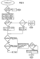
Die oben erwähnte Ermittlung der Verzögerungszeit D durch die Leaky-Bucket-Steuereinrichtung LBM wird nachfolgend anhand eines Ausführungsbeispiels unter Bezugnahme auf ein in FIG 3 dargestelltes Flußdiagramm näher beschrieben. Hierzu sei als Beispiel davon ausgegangen, daß zwei unterschiedliche Arten von VBR-Verbindungen auftreten mögen, für deren zugehörige Nachrichtenzellen eine hohe Zellenverlustpriorität CLP=0 oder eine niedrige Zellenverlustpriorität CLP=1 festgelegt werden kann. Eine erste Art von VBR-Verbindungen, die im folgenden als 1-Verbindungen bezeichnet sind, wird im Zuge des jeweiligen Verbindungsaufbaus durch eine Spitzenbitrate Rp und eine Obergrenze für die mittlere Bitrate Rs mit einer Burst-Toleranz τs für den gesamten übertragenen Nachrichtenzellenstrom, d.h. unter Berücksichtigung der Nachrichtenzellen mit den Zellenverlustprioritäten CLP=0 und CLP=1, charakterisiert. Eine zweite Art von VBR-Verbindungen, die als 2-Verbindungen bezeichnet sind, wird dagegen durch eine Spitzenbitrate Rp für den gesamten übertragenen Nachrichtenzellenstrom und durch die Obergrenze der mittleren Bitrate Rs mit einer Burst-Toleranz ds für mit hoher Zellenverlustpriorität CLP=0 zu übertragende Nachrichtenzellen charakterisiert.The above-mentioned determination of the delay time D by the leaky bucket control device LBM is described in more detail below using an exemplary embodiment with reference to a flowchart shown in FIG. As an example, assume that two different types of VBR connections may occur, for the associated message cells of which a high cell loss priority CLP = 0 or a low cell loss priority CLP = 1 can be specified. A first type of VBR connections, which are referred to below as 1 connections, is characterized by a peak bit rate Rp and an upper limit for the average bit rate Rs with a burst tolerance in the course of the respective connection setup τs for the entire transmitted message cell stream, ie taking into account the message cells with the cell loss priorities CLP = 0 and CLP = 1. A second type of VBR connection, which is referred to as 2 connections, on the other hand is characterized by a peak bit rate Rp for the entire transmitted message cell stream and by the upper limit of the average bit rate Rs with a burst tolerance ds for CLP = 0 to be transmitted with high cell loss priority Characterized message cells.
In der Leaky-Bucket-Steuereinrichtung LBM sind für jede der VBR-Verbindungen zwei Leaky-Bucket-Parametersätze sowie zwei Leaky-Bucket-Zähler LB geführt, nämlich ein Leaky-Bucket-Zähler LB(PCR) für die Spitzenbitrate sowie ein Leaky-Bucket-Zähler LB(SCR) für die Obergrenze der mittleren Bitrate. Die Funktionsweise eines solchen Leaky-Bucket-Zählers ist bereits bekannt. Außerdem sind die Leaky-Bucket-Parameter beispielsweise durch ATM-Forum: "ATM User-Network Interface Specification", Sept. 1993, definiert. Darüber hinaus wird durch die Leaky-Bucket-Steuereinrichtung LBM die Anzahl N der in der Behandlungseinrichtung SH momentan enthaltenen VBR-Nachrichtenzellen erfaßt. Diese Anzahl N wird dabei mit jeder aufgenommenen bzw. weitergeleiteten Nachrichtenzelle aktualisiert. Daneben wird eine Obergrenze N1 für die Anzahl der VBR-Nachrichtenzellen mit der niedrigen Zellenverlustpriorität CLP=1 festgehalten.In the leaky bucket control device LBM, two leaky bucket parameter sets and two leaky bucket counters LB are kept for each of the VBR connections, namely a leaky bucket counter LB (PCR) for the peak bit rate and a leaky bucket Counter LB (SCR) for the upper limit of the average bit rate. The operation of such a leaky bucket counter is already known. In addition, the leaky bucket parameters are defined, for example, by ATM Forum: "ATM User Network Interface Specification", Sept. 1993. In addition, the leaky bucket control device LBM detects the number N of VBR message cells currently contained in the treatment device SH. This number N is updated with each recorded or forwarded message cell. In addition, an upper limit N1 for the number of VBR message cells with the low cell loss priority CLP = 1 is recorded.
Mit dem Auftreten einer Nachrichtenzelle wird anhand der in dieser geführten VPI/VCI ermittelt, ob diese Nachrichtenzelle einer 2-Verbindung zugehörig und gleichzeitig CLP=1 und N>N1 gegeben ist. Ist dies der Fall, so wird der Zellenpuffer-Steuereinrichtung CBM eine Verzögerungszeit D=0 mitgeteilt, woraufhin die gerade zugeführte Nachrichtenzelle verworfen wird. D. h. Nachrichtenzellen einer 2-Verbindung mit CLP=1 werden verworfen, falls bereits viele VBR-Verbindungen zugehörige Nachrichtenzellen gespeichert sind.When a message cell occurs, the VPI / VCI carried in it determines whether this message cell belongs to a 2 connection and, at the same time, gives CLP = 1 and N> N1. If this is the case, the cell buffer control device CBM is informed of a delay time D = 0, whereupon the message cell just supplied is discarded. That is, Message cells of a 2 connection with CLP = 1 are rejected if many message cells associated with VBR connections are already stored.
Anderenfalls werden die momentanen Zählerstände der beiden Leaky-Bucket-Zähler LB(PCR) und LB(SCR) jeweils um einen Wert (T-Talt) dekrementiert, wobei T die oben bereits erwähnte aktuelle Zeit, Talt dagegen die Zeit angibt, zu der für die in Frage kommende Verbindung zuletzt eine Nachrichtenzelle aufgenommen worden ist. Damit ergibt sich für den Leaky-Bucket-Zähler LB(PCR) ein neuer Zählerstand ![]()
![]()
![]()
ermittelt, wobei c eine festgelegte Konstante ("scheduling constant"), N die oben genannte Anzahl von VBR-Nachrichtenzellen und K eine von der zulässigen Zellen-Verzögerungszeitschwankung abhängige Konstante darstellen. c ist bei dem vorliegenden Ausführungsbeispiel mit ![]()
![]()
![]()
![]()
![]()
![]()
![]()
![]()
where c is a scheduling constant, N is the above number of VBR message cells, and K is a constant dependent on the allowable cell delay time variation. c is with in the present embodiment ![]()
![]()
![]()
![]()
![]()
Anschließend wird überprüft, ob die vorliegende Nachrichtenzelle einer 2-Verbindung zugehörig und CLP=1 gegeben ist, d.h. daß eine niedrige Zellenverlustpriorität vorliegt. Ist dies der Fall und ist der Zählerstand des Leaky-Bucket-Zählers LB(PCR) ![]()
![]()
![]()
und eine maximale Verzögerungszeit![]()
festgelegt.It is then checked whether the present message cell belongs to a 2 connection and CLP = 1, ie that there is a low cell loss priority. If this is the case and is the counter reading of the leaky bucket counter LB (PCR) ![]()
![]()
![]()
and a maximum delay time ![]()
fixed.
Liegt dagegen für den Leaky-Bucket-Zähler LP(PCR) ein Zählerstand ![]()
![]()
Ergibt die zuvor genannte, nach der Ermittlung der optimalen Verzögerungszeit Dopt durchgeführte Abfrage, daß keine 2-Verbindung mit CLP=1 vorliegt, so wird die minimale Verzögerungszeit Dmin mit![]()
festgelegt. Die maximale Verzögerungszeit Dmax wird dagegen auf den Wert![]()
gesetzt.If the aforementioned query carried out after determining the optimal delay time Dopt shows that there is no 2 connection with CLP = 1, the minimum delay time Dmin becomes ![]()
fixed. The maximal Delay time Dmax, however, is reduced to the value ![]()
set.
Nachdem die minimalen und maximalen Verzögerungszeiten ermittelt worden sind, wird nachfolgend überprüft, ob die ermittelte optimale Verzögerungszeit Dopt zwischen der minimalen und maximalen Verzögerungszeit Dmin und Dmax liegt. Ist dies der Fall, so wird als Verzögerungszeit D der Wert D=Dopt verwendet. Andernfalls wird bei Dopt≦Dmin die Verzögerungszeit ![]()
![]()
![]()
![]()
Danach wird der zahlerstand des Leaky-Bucket-Zählers LB(PCR) auf den Wert ![]()
![]()
![]()
![]()
![]()
![]()
Abschließend wird dann der ermittelte Verzögerungswert D auf den Wert D:=D+1 gesetzt, der dann der Zellenpuffer-Steuereinrichtung CBM in der oben angegebenen Weise für die weitere Behandlung einer gerade vorliegenden Nachrichtenzelle zugeführt wird. Die anhand der FIG 3 erläuterten Steuerungsvorgänge wiederholen sich dann mit jedem Auftreten einer weiteren Nachrichtenzelle.Finally, the determined delay value D is then set to the value D: = D + 1, which is then fed to the cell buffer control device CBM in the manner specified above for the further treatment of a message cell that is currently present. The control processes explained with reference to FIG. 3 then repeat each time a further message cell occurs.
Im übrigen wird durch das Setzen der Verzögerungszeit auf den Wert D:=D+1 erreicht, daß eine eintreffende Nachrichtenzelle wenigstens um eine Zeit D=1 verzögert wird, d.h. daß diese Nachrichtenzelle frühestens im nächsten Zellenzyklus weitergeleitet wird. Damit wird die Behandlung eintreffender Nachrichtenzellen von der Behandlung weiterzuleitender Nachrichtenzellen entkoppelt.Moreover, by setting the delay time to the value D: = D + 1 it is achieved that an incoming message cell is delayed at least by a time D = 1, i.e. that this message cell is forwarded at the earliest in the next cell cycle. This decouples the treatment of incoming message cells from the treatment of message cells to be forwarded.
Claims (8)
und wobei die den einzelnen Zeitschlitzen zugeordneten Ausgabe-Listen nacheinander für eine Weiterleitung der in diesen jeweils enthaltenen Nachrichtenzelle bzw. Nachrichtenzellen ausgewählt werden,
dadurch gekennzeichnet,
daß als charakteristische Parameter zumindest für eine erste Art von virtuellen Verbindungen jeweils eine Spitzenbitrate sowie eine obere Grenze für eine mittlere Bitrate und eine Burst-Toleranz festgelegt werden,
daß einerseits nach Maßgabe der Anzahl der im Zuge der jeweiligen virtuellen Verbindung unter Berücksichtigung der Spitzenbitrate pro Zeiteinheit zufließenden und abfließenden Nachrichtenzellen eine minimale Verzögerungszeit ermittelt wird, um welche die Weiterleitung einer gerade zugeführten Nachrichtenzelle mindestens zu verzögern ist,
daß andererseits nach Maßgabe der Anzahl der im Zuge der jeweiligen virtuellen Verbindung unter Berücksichtigung der oberen Grenze der mittleren Bitrate pro Zeiteinheit zufließenden und abfließenden Nachrichtenzellen eine maximale Verzögerungszeit ermittelt wird, um welche die Weiterleitung einer gerade zugeführte Nachrichtenzelle höchstens zu verzögern ist,
und daß unter Berücksichtigung der minimalen und der maximalen Verzögerungszeit eine Verzögerungszeit und damit der Zeitschlitz festgelegt wird, in welchem die betreffende Nachrichtenzelle weiterzuleiten ist.Method for forwarding an ATM communication device operating according to an asynchronous transfer mode in the course of virtual connections via at least one feeder line supplied message cells to a customer line (AL) in question for the respective virtual connection, on which periodically occurring time frames for the forwarding of message cells also occur A plurality of time slots is defined in each case, characteristic parameters for the respective virtual connection being established in the course of establishing the connection, by means of which the message cell stream of the respective virtual connection is defined, and in accordance with these characteristic parameters and the number of those in the course of the respective virtual connection per time unit incoming and outgoing message cells determined for each received message cell a preferred time slot for its forwarding and the respective messages cell is inserted into an output list assigned to the time slot to be used,
and the output lists assigned to the individual time slots are selected one after the other for forwarding the message cell or message cells contained therein,
characterized,
that a peak bit rate and an upper limit for an average bit rate and a burst tolerance are defined as characteristic parameters at least for a first type of virtual connection,
that, on the one hand, a minimum delay time is determined in accordance with the number of message cells flowing in and out in the course of the respective virtual connection, taking into account the peak bit rate per time unit, by which the forwarding of a message cell that has just been supplied is at least delayed,
that, on the other hand, a maximum delay time is determined in accordance with the number of message cells flowing in and out in the course of the respective virtual connection, taking into account the upper limit of the average bit rate per unit of time, by which the forwarding of a message cell which has just been fed is to be delayed at most,
and that taking into account the minimum and maximum delay time, a delay time and thus the time slot in which the message cell in question is to be forwarded is determined.
dadurch gekennzeichnet,
daß die Verzögerungszeit als ganzzahlige Anzahl von Zeitschlitzen ermittelt wird
und daß eine Nachrichtenzelle lediglich dann weitergeleitet wird, wenn für diese eine Verzögerungszeit > 0 ermittelt worden ist.Method according to claim 1,
characterized,
that the delay time is determined as an integer number of time slots
and that a message cell is only forwarded if a delay time> 0 has been determined for it.
dadurch gekennzeichnet,
daß eine optimale Verzögerungszeit aus einem Wert proportional zur Anzahl der momentan für eine Weiterleitung anstehenden Nachrichtenzellen ermittelt wird,
daß dieser Wert berücksichtigt wird, falls dieser in dem Intervall zwischen minimaler und maximaler Verzögerungszeit liegt,
und daß bei einer optimalen Verzögerungszeit, die kleiner oder gleich der minimalen Verzögerungszeit ist, die minimale Verzögerungszeit bzw. bei einer optimalen Verzögerungszeit, die größer oder gleich der maximalen Verzögerungszeit ist, die maximale Verzögerungszeit berücksichtigt wird.The method of claim 1 or 2,
characterized,
that an optimal delay time is determined from a value proportional to the number of message cells currently pending for forwarding,
that this value is taken into account if it lies in the interval between the minimum and maximum delay time,
and that with an optimal delay time that is less than or equal to the minimum delay time, the minimum delay time or with an optimal delay time that is greater than or equal to the maximum delay time, the maximum delay time is taken into account.
dadurch gekennzeichnet,
daß über die jeweilige Abnehmerleitung neben der ersten Art von virtuellen Verbindungen eine zweite und eine dritte Art von virtuellen Verbindungen verlaufen,
daß für die zweite Art von virtuellen Verbindungen als charakteristische Parameter eine Spitzenbitrate festgelegt wird, daß für die dritte Art von virtuellen Verbindungen von der ersten und zweiten Art von virtuellen Verbindungen abweichende charakteristische Parameter festgelegt sind
und daß Nachrichtenzellen der zweiten und dritten Art von virtuellen Verbindungen ohne Ermittlung einer Verzögerungszeit weitergeleitet werden, wobei für die Weiterleitung von Nachrichtenzellen den virtuellen Verbindungen der zweiten Art Priorität gegenüber den virtuellen Verbindungen der ersten Art und diesen wiederum Priorität gegenüber den virtuellen Verbindungen der dritten Art von virtuellen Verbindungen eingeräumt wird.Method according to one of claims 1 to 3,
characterized,
that in addition to the first type of virtual connections, a second and a third type of virtual connections run via the respective customer line,
that a peak bit rate is defined as characteristic parameters for the second type of virtual connections, that characteristic parameters deviating from the first and second types of virtual connections are specified for the third type of virtual connections
and that message cells of the second and third type of virtual connections are forwarded without determining a delay time, wherein for the forwarding of message cells the virtual connections of the second type have priority over the virtual connections of the first type and these in turn have priority over the virtual connections of the third type of virtual connections.
und wobei die den einzelnen Zeitschlitzen zugeordneten Ausgabe-Listen nacheinander für eine Weiterleitung der in diesen jeweils enthaltenen Nachrichtenzelle bzw. Nachrichtenzellen ausgewählt werden,
dadurch gekennzeichnet,
daß zumindest in einem Teil von mit der ATM-Kommunikationseinrichtung verbundenen Teilnehmereinrichtungen Mittel zur Abgabe von charakteristischen Parametern für die jeweilige virtuelle Verbindung bezüglich einer Spitzenbitrate sowie einer oberen Grenze für eine mittlere Bitrate und einer Burst-Toleranz vorgesehen sind,
daß der jeweiligen Abnehmerleitung Behandlungsmittel (SH) zugeordnet sind, welche derart ausgebildet sind,
daß nach Maßgabe der Anzahl der im Zuge der jeweiligen virtuellen Verbindung unter Berücksichtigung der Spitzenbitrate pro Zeiteinheit zufließenden und abfließenden Nachrichtenzellen eine minimale Verzögerungszeit ermittelt wird, um welche die Weiterleitung einer gerade zugeführten Nachrichtenzelle mindestens zu verzögern ist,
daß andererseits nach Maßgabe der Anzahl der im Zuge der jeweiligen virtuellen Verbindung unter Berücksichtigung der oberen Grenze der mittleren Bitrate pro Zeiteinheit zufließenden und abfließenden Nachrichtenzellen eine maximale Verzögerungszeit ermittelt wird, um welche die Weiterleitung einer gerade zugeführte Nachrichtenzelle höchstens zu verzögern ist
und daß unter Berücksichtigung der minimalen und der maximalen Verzögerungszeit eine Verzögerungszeit und damit der Zeitschlitz festgelegt wird, in welchem die betreffende Nachrichtenzelle weiterzuleiten ist.Circuit arrangement for forwarding an ATM communication device operating according to an asynchronous transfer mode in the course of virtual connections via at least one feeder line supplied message cells to a customer line (AL) in question for the respective virtual connection, on which periodically occurring time frames for the forwarding of message cells also occur A plurality of time slots is defined in each case, characteristic parameters for the respective virtual connection being established in the course of establishing the connection, by means of which the message cell stream of the respective virtual connection is defined, and in accordance with these characteristic parameters and the number of those in the course of the respective virtual connection per time unit incoming and outgoing message cells for each recorded message cell to determine a time slot to be used for forwarding and the respective e message cell in an output list assigned to the time slot to be used is inserted,
and the output lists assigned to the individual time slots are selected one after the other for forwarding the message cell or message cells contained therein,
characterized,
that means for delivering characteristic parameters for the respective virtual connection with respect to a peak bit rate and an upper limit for an average bit rate and a burst tolerance are provided in at least some of the subscriber devices connected to the ATM communication device,
that the respective customer line is assigned treatment agents (SH) which are designed in such a way
that a minimum delay time is determined in accordance with the number of message cells flowing in and out in the course of the respective virtual connection, taking into account the peak bit rate per unit of time, by which the forwarding of a message cell that has just been supplied is at least delayed,
that, on the other hand, a maximum delay time is determined in accordance with the number of message cells flowing in and out in the course of the respective virtual connection, taking into account the upper limit of the average bit rate per unit of time, by which the forwarding of a message cell which has just been fed is to be delayed at most
and that taking into account the minimum and maximum delay time, a delay time and thus the time slot in which the message cell in question is to be forwarded is determined.
dadurch gekennzeichnet,
daß die Behandlungsmittel (SH) weiter derart ausgebildet sind,
daß die Verzögerungszeit als ganzzahlige Anzahl von Zeitschlitzen angegeben ist
und daß eine gerade aufgenommene Nachrichtenzelle lediglich dann weitergeleitet wird, wenn die dafür ermittelte Verzögerungszeit > 0 ist.Circuit arrangement according to claim 5,
characterized,
that the treatment agents (SH) are further designed such
that the delay time is specified as an integer number of time slots
and that a message cell that has just been recorded is only forwarded if the delay time determined for it is> 0.
dadurch gekennzeichnet,
daß die Behandlungsmittel (SH) für jede der virtuellen Verbindungen über zwei Zähleinrichtungen verfügt, von denen eine erste Zähleinrichtung (LB(PCR)) zur Erfassung der pro Zeiteinheit zufließenden und abfließenden Nachrichtenzellen unter Berücksichtung der Spitzenbitrate, die verbleibende zweite Zähleinrichtung (LB(SCR)) dagegen zur Erfassung der pro Zeiteinheit zufließenden und abfließenden Nachrichtenzellen unter Berücksichtung der oberen Grenze der mittleren Bitrate dient, daß der momentane Zählerstand beider Zähleinrichtungen bei Auftreten einer Nachrichtenzelle um den Wert (T-Talt) dekrementiert wird, wobei T die aktuelle Zeit und Talt die Zeit, zu der zuletzt eine Nachrichtenzelle der jeweiligen Verbindung aufgetreten ist, bezeichnen,
daß aus den daraus resultierenden momentanen Zählerständen der beiden Zähleinrichtungen eine minimale und eine maximale Verzögerungszeit ermittelt wird,
daß zusätzlich eine optimale Verzögerungszeit aus einem Wert proportional zur Anzahl der momentan für eine Weiterleitung anstehenden Nachrichtenzellen ermittelt wird,
daß dieser Wert berücksichtigt wird, falls dieser in dem Intervall zwischen minimaler und maximaler Verzögerungszeit liegt,
und daß bei einer optimalen Verzögerungszeit, die kleiner oder gleich der minimalen Verzögerungszeit ist, die minimale Verzögerungszeit bzw. bei einer optimalen Verzögerungszeit, die größer oder gleich der maximalen Verzögerungszeit ist, die maximale Verzögerungszeit berücksichtigt wird.Circuit arrangement according to claim 5 or 6,
characterized,
that the treatment means (SH) has two counting devices for each of the virtual connections, of which a first counting device (LB (PCR)) for recording the incoming and outgoing message cells per unit of time, taking into account the peak bit rate, the remaining second counting device (LB (SCR) ), on the other hand, to record the incoming and outgoing message cells per unit of time, taking into account the upper limit of the average bit rate, that the current count of both counters is decremented by the value (T-Talt) when a message cell occurs, where T is the current time and Talt the Time at which a message cell of the respective connection occurred last,
that a minimum and a maximum delay time are determined from the resulting instantaneous counter readings of the two counter devices,
that in addition an optimal delay time is determined from a value proportional to the number of message cells currently pending for forwarding,
that this value is taken into account if it lies in the interval between the minimum and maximum delay time,
and that with an optimal delay time that is less than or equal to the minimum delay time, the minimum delay time or with an optimal delay time that is greater than or equal to the maximum delay time, the maximum delay time is taken into account.
dadurch gekennzeichnet,
daß den Behandlungsmitteln (SH) zusätzlich Nachrichtenzellen einer zweiten Art von virtuellen Verbindungen, welche jeweils durch eine Spitzenbitrate charakterisiert sind, und einer dritten Art von virtuellen Verbindungen, welche jeweils durch von der ersten und zweiten Art von virtuellen Verbindungen zumindest teilweise abweichende charakteristische Parameter charakterisiert sind, zugeführt sind,
daß den drei Arten von virtuellen Verbindungen jeweils eine gesonderte, für die Aufnahme von weiterzuleitenden Nachrichtenzellen dienende Ausgangs-Warteschlange (CBR-QU, VBR-QU, ABR-QU) zugeordnet sind,
daß Nachrichtenzellen der ersten Art von virtuellen Verbindungen der zugeordneten Ausgangs-Warteschlange (VBR-QU) jeweils entsprechend der ermittelten Verzögerungszeit, Nachrichtenzellen der zweiten und dritten Art von virtuellen Verbindungen dagegen direkt der jeweils zugeordneten Ausgangs-Warteschlange (CBR-QU, ABR-QU) zugeführt sind und daß die Ausgangs-Warteschlangen durch mit diesen ausgangsseitig verbundene Auswahlmittel (OC) derart ansteuerbar sind, daß hinsichtlich der zeitschlitzweisen Weiterleitung Nachrichtenzellen der zweiten Art von virtuellen Verbindungen Priorität gegenüber Nachrichtenzellen der ersten Art von virtuellen Verbindungen und diese wiederum Priorität gegenüber Nachrichtenzellen der dritten Art von virtuellen Verbindungen besitzen.Circuit arrangement according to one of claims 5 to 7,
characterized,
that the treatment means (SH) additionally have message cells of a second type of virtual connection, each of which is characterized by a peak bit rate, and a third type of virtual connection, each of which is characterized by characteristic parameters that differ at least partially from the first and second types of virtual connections are fed,
that the three types of virtual connections are each assigned a separate output queue (CBR-QU, VBR-QU, ABR-QU) which is used to receive message cells to be forwarded,
that message cells of the first type of virtual connections of the assigned output queue (VBR-QU) each correspond to the determined delay time, message cells of the second and third type of virtual connections, on the other hand, directly to the respectively assigned output queue (CBR-QU, ABR-QU) are supplied and that the output queues can be controlled by means of selection means (OC) connected to them on the output side in such a way that, with regard to the time-slot forwarding, message cells of the second type of virtual connections have priority over message cells of the first type of virtual connections and these in turn have priority over message cells of the third Own kind of virtual connections.
Applications Claiming Priority (2)
| Application Number | Priority Date | Filing Date | Title |
|---|---|---|---|
| DE4434724A DE4434724C1 (en) | 1994-09-28 | 1994-09-28 | Information cell handling for asynchronous transfer mode communications device |
| DE4434724 | 1994-09-28 |
Publications (2)
| Publication Number | Publication Date |
|---|---|
| EP0705049A2 true EP0705049A2 (en) | 1996-04-03 |
| EP0705049A3 EP0705049A3 (en) | 1998-08-26 |
Family
ID=6529455
Family Applications (1)
| Application Number | Title | Priority Date | Filing Date |
|---|---|---|---|
| EP95113938A Withdrawn EP0705049A3 (en) | 1994-09-28 | 1995-09-05 | Method and apparatus for scheduling the transmission of ATM cells |
Country Status (4)
| Country | Link |
|---|---|
| US (1) | US5754529A (en) |
| EP (1) | EP0705049A3 (en) |
| CA (1) | CA2159173A1 (en) |
| DE (1) | DE4434724C1 (en) |
Cited By (1)
| Publication number | Priority date | Publication date | Assignee | Title |
|---|---|---|---|---|
| EP0800296A2 (en) * | 1996-04-05 | 1997-10-08 | Fore Systems, Inc. | Digital network including mechanism for grouping virtual message transfer paths having similar transfer service rates to facilitate efficient scheduling of transfers thereover |
Families Citing this family (15)
| Publication number | Priority date | Publication date | Assignee | Title |
|---|---|---|---|---|
| EP0798897A3 (en) | 1996-03-26 | 1999-07-14 | Digital Equipment Corporation | Method and apparatus for relative error scheduling using discrete rates and proportional rate scaling |
| US6134217A (en) * | 1996-04-15 | 2000-10-17 | The Regents Of The University Of California | Traffic scheduling system and method for packet-switched networks with fairness and low latency |
| US5946297A (en) * | 1996-05-31 | 1999-08-31 | International Business Machines Corporation | Scheduling method and apparatus for supporting ATM connections having a guaranteed minimun bandwidth |
| FR2750283B1 (en) * | 1996-06-20 | 1998-07-31 | Quinquis Jean Paul | LOCAL MOBILE ACCESS NETWORK PROVIDED WITH MEANS FOR MANAGING RESOURCES IN SUCH A NETWORK |
| KR100204059B1 (en) * | 1996-10-11 | 1999-06-15 | 이계철 | Wide band terminal equipment for controlling congestion in ring structure |
| US5933414A (en) * | 1996-10-29 | 1999-08-03 | International Business Machines Corporation | Method to control jitter in high-speed packet-switched networks |
| FI970998A (en) * | 1997-03-10 | 1998-11-13 | Nokia Telecommunications Oy | Procedure for determining whether to allow a connection on a broadband network |
| US6934253B2 (en) * | 1998-01-14 | 2005-08-23 | Alcatel | ATM switch with rate-limiting congestion control |
| DE19803758A1 (en) * | 1998-01-30 | 1999-08-12 | Siemens Ag | Method for controlling access to resources of a communication network |
| US6608816B1 (en) * | 1998-11-18 | 2003-08-19 | Nortel Networks Limited | Method and apparatus for providing differentiated services using a multi-level queuing mechanism |
| US6425032B1 (en) * | 1999-04-15 | 2002-07-23 | Lucent Technologies Inc. | Bus controller handling a dynamically changing mix of multiple nonpre-emptable periodic and aperiodic devices |
| CA2276681A1 (en) * | 1999-06-30 | 2000-12-30 | Newbridge Networks Corporation | Subscriber permissions and restrictions for switched connections in a communications network |
| AU6765200A (en) * | 1999-08-13 | 2001-03-13 | Fujitsu Network Communications, Inc. | Supporting multiple application traffic types over connection oriented networks |
| DE10054915B4 (en) * | 2000-11-06 | 2005-10-06 | Infineon Technologies Ag | Scalable data network routers and methods for aggregating and relaying data routed to a router |
| US7039056B2 (en) * | 2001-08-02 | 2006-05-02 | Lucent Technologies Inc. | High quality audio and video over digital subscriber lines (DSLs) |
Family Cites Families (7)
| Publication number | Priority date | Publication date | Assignee | Title |
|---|---|---|---|---|
| ES2072537T3 (en) * | 1991-02-01 | 1995-07-16 | Siemens Ag | PROCEDURE FOR THE CONTROL AND EQUALIZATION OF DATA CURRENTS, WHICH ARE TRANSMITTED ACCORDING TO AN ASYNCHRONOUS TRANSMISSION PROCEDURE. |
| DE59108304D1 (en) * | 1991-08-27 | 1996-11-28 | Siemens Ag | Arrangement for bit rate monitoring in ATM networks |
| FR2686205B1 (en) * | 1992-01-14 | 1994-03-25 | Pierre Boyer | METHOD FOR MONITORING CELL FLOW. |
| CA2104753C (en) * | 1992-10-29 | 1999-02-16 | Kotikalapudi Sriram | Bandwidth allocation, transmission scheduling, and congestion avoidance in broadband atm networks |
| EP0660557A1 (en) * | 1993-12-23 | 1995-06-28 | Siemens Aktiengesellschaft | Method for statistical multiplexing |
| GB2288097B (en) * | 1994-03-23 | 1998-09-23 | Roke Manor Research | ATM queuing and scheduling apparatus |
| US5524006A (en) * | 1995-02-15 | 1996-06-04 | Motorola, Inc. | Second-order leaky bucket device and method for traffic management in cell relay networks |
-
1994
- 1994-09-28 DE DE4434724A patent/DE4434724C1/en not_active Expired - Fee Related
-
1995
- 1995-09-05 EP EP95113938A patent/EP0705049A3/en not_active Withdrawn
- 1995-09-21 US US08/531,704 patent/US5754529A/en not_active Expired - Fee Related
- 1995-09-26 CA CA002159173A patent/CA2159173A1/en not_active Abandoned
Cited By (2)
| Publication number | Priority date | Publication date | Assignee | Title |
|---|---|---|---|---|
| EP0800296A2 (en) * | 1996-04-05 | 1997-10-08 | Fore Systems, Inc. | Digital network including mechanism for grouping virtual message transfer paths having similar transfer service rates to facilitate efficient scheduling of transfers thereover |
| EP0800296A3 (en) * | 1996-04-05 | 1999-09-08 | Fore Systems, Inc. | Digital network including mechanism for grouping virtual message transfer paths having similar transfer service rates to facilitate efficient scheduling of transfers thereover |
Also Published As
| Publication number | Publication date |
|---|---|
| US5754529A (en) | 1998-05-19 |
| DE4434724C1 (en) | 1995-11-23 |
| CA2159173A1 (en) | 1996-03-29 |
| EP0705049A3 (en) | 1998-08-26 |
Similar Documents
| Publication | Publication Date | Title |
|---|---|---|
| DE19709258B4 (en) | Feedback control method and associated device in an ATM switching system | |
| DE69632240T2 (en) | Method and system for controlling transmission speeds of sources in ATM networks | |
| EP0529351B1 (en) | Arrangement for monitoring the bit rate in ATM-networks | |
| DE69634857T2 (en) | EXPIRATION CONTROL FOR INFORMATION PACKET TRANSMISSION | |
| EP0529127B1 (en) | Circuit for monitoring the bit rate in ATM-networks | |
| DE4434724C1 (en) | Information cell handling for asynchronous transfer mode communications device | |
| EP0419959B1 (en) | Circuit arrangement for testing the adherence to pre-established bit rates in the transmission of information cells | |
| EP0470283B1 (en) | Method and circuit arrangement for determining the quality of virtual circuits going through an ATM switching arrangement | |
| EP0566961B1 (en) | Method and circuit to enforce the preassigned transmission rate in an ATM switching equipment | |
| EP0730362A2 (en) | Method and circuitry for transfer of data packets, transferred by an ATM communication system, to an output line | |
| EP0645919A2 (en) | Method for transmitting of message cells through redundant virtual path pairs of a ATM-communication network | |
| EP0645918A2 (en) | Method and circuit arrangement for transmitting of message cells through redundant virtual path pairs of a ATM-communication network | |
| EP0498092B1 (en) | Method for monitoring and smoothing asynchronously transmitted data streams | |
| EP0419958A2 (en) | Circuit arrangement for detecting the data quantity transmitted in an ATM-switching system and for checking compliance with specified bit rates | |
| EP0730361A2 (en) | Circuitry for intake and transfer of data packets on an ATM communication network | |
| DE69736623T2 (en) | Packet-switched communication system and method of traffic shaping | |
| DE69532440T2 (en) | METHOD FOR REDIRECTING A DATA CONNECTION IN PACKAGE MODE | |
| EP0660557A1 (en) | Method for statistical multiplexing | |
| EP0673136A1 (en) | Method and circuit arrangement for controlling the transmission of data blocks within a communication system | |
| EP0870416B1 (en) | Process for prioritising of cell streams in systems which transmit data in an asynchronous mode (atm) | |
| DE69917336T2 (en) | SYSTEM AND METHOD FOR DETERMINING MINIMUM AND MAXIMUM VALUES USING LAST-EVENT AND SLIDING WIND TECHNOLOGIES | |
| EP1097605A2 (en) | Method and circuit for creating data signal links | |
| EP0720411B1 (en) | Method and system for policing an ATM-cell stream | |
| EP0916231B1 (en) | Process for optimising load distribution between connection sections of data package transmission systems | |
| EP0900513B1 (en) | Process for optimizing the utilization of connecting links in systems which transmit data in data packets |
Legal Events
| Date | Code | Title | Description |
|---|---|---|---|
| PUAI | Public reference made under article 153(3) epc to a published international application that has entered the european phase |
Free format text: ORIGINAL CODE: 0009012 |
|
| AK | Designated contracting states |
Kind code of ref document: A2 Designated state(s): AT BE CH DE DK ES FR GB IT LI NL SE |
|
| PUAL | Search report despatched |
Free format text: ORIGINAL CODE: 0009013 |
|
| AK | Designated contracting states |
Kind code of ref document: A3 Designated state(s): AT BE CH DE DK ES FR GB IT LI NL SE |
|
| 17P | Request for examination filed |
Effective date: 19980917 |
|
| STAA | Information on the status of an ep patent application or granted ep patent |
Free format text: STATUS: THE APPLICATION IS DEEMED TO BE WITHDRAWN |
|
| 18D | Application deemed to be withdrawn |
Effective date: 20000401 |