EP0704775A1 - Method and apparatus for estimating relevant quantity in the manufacture of textile products - Google Patents
Method and apparatus for estimating relevant quantity in the manufacture of textile products Download PDFInfo
- Publication number
- EP0704775A1 EP0704775A1 EP95111497A EP95111497A EP0704775A1 EP 0704775 A1 EP0704775 A1 EP 0704775A1 EP 95111497 A EP95111497 A EP 95111497A EP 95111497 A EP95111497 A EP 95111497A EP 0704775 A1 EP0704775 A1 EP 0704775A1
- Authority
- EP
- European Patent Office
- Prior art keywords
- data
- products
- model
- input
- process model
- Prior art date
- Legal status (The legal status is an assumption and is not a legal conclusion. Google has not performed a legal analysis and makes no representation as to the accuracy of the status listed.)
- Withdrawn
Links
- 238000000034 method Methods 0.000 title claims abstract description 77
- 239000004753 textile Substances 0.000 title abstract description 8
- 238000004519 manufacturing process Methods 0.000 title description 8
- 230000008569 process Effects 0.000 claims abstract description 49
- 238000009987 spinning Methods 0.000 claims abstract description 26
- 238000013528 artificial neural network Methods 0.000 claims abstract description 15
- 238000012545 processing Methods 0.000 claims description 29
- 238000012360 testing method Methods 0.000 claims description 25
- 230000015654 memory Effects 0.000 claims description 11
- 230000006870 function Effects 0.000 claims description 4
- 230000006399 behavior Effects 0.000 claims description 3
- 230000005540 biological transmission Effects 0.000 claims description 3
- 238000005259 measurement Methods 0.000 claims description 2
- 239000000463 material Substances 0.000 abstract description 32
- 238000012549 training Methods 0.000 abstract description 3
- 239000000047 product Substances 0.000 description 21
- 230000008901 benefit Effects 0.000 description 4
- 239000000835 fiber Substances 0.000 description 4
- 230000015572 biosynthetic process Effects 0.000 description 3
- 238000012546 transfer Methods 0.000 description 3
- 238000012935 Averaging Methods 0.000 description 2
- 238000009826 distribution Methods 0.000 description 2
- 238000002474 experimental method Methods 0.000 description 2
- 230000003993 interaction Effects 0.000 description 2
- 238000012417 linear regression Methods 0.000 description 2
- 230000006855 networking Effects 0.000 description 2
- 230000009022 nonlinear effect Effects 0.000 description 2
- 238000004088 simulation Methods 0.000 description 2
- 238000009960 carding Methods 0.000 description 1
- 230000008859 change Effects 0.000 description 1
- 238000010276 construction Methods 0.000 description 1
- 230000007547 defect Effects 0.000 description 1
- 238000010586 diagram Methods 0.000 description 1
- 238000005516 engineering process Methods 0.000 description 1
- 238000011156 evaluation Methods 0.000 description 1
- 239000012535 impurity Substances 0.000 description 1
- 239000013067 intermediate product Substances 0.000 description 1
- 239000011159 matrix material Substances 0.000 description 1
- 238000012544 monitoring process Methods 0.000 description 1
- 239000004745 nonwoven fabric Substances 0.000 description 1
- 238000007383 open-end spinning Methods 0.000 description 1
- 238000007378 ring spinning Methods 0.000 description 1
- 239000007858 starting material Substances 0.000 description 1
- 230000001960 triggered effect Effects 0.000 description 1
Images


Classifications
-
- G—PHYSICS
- G05—CONTROLLING; REGULATING
- G05B—CONTROL OR REGULATING SYSTEMS IN GENERAL; FUNCTIONAL ELEMENTS OF SUCH SYSTEMS; MONITORING OR TESTING ARRANGEMENTS FOR SUCH SYSTEMS OR ELEMENTS
- G05B17/00—Systems involving the use of models or simulators of said systems
- G05B17/02—Systems involving the use of models or simulators of said systems electric
-
- G—PHYSICS
- G05—CONTROLLING; REGULATING
- G05B—CONTROL OR REGULATING SYSTEMS IN GENERAL; FUNCTIONAL ELEMENTS OF SUCH SYSTEMS; MONITORING OR TESTING ARRANGEMENTS FOR SUCH SYSTEMS OR ELEMENTS
- G05B13/00—Adaptive control systems, i.e. systems automatically adjusting themselves to have a performance which is optimum according to some preassigned criterion
- G05B13/02—Adaptive control systems, i.e. systems automatically adjusting themselves to have a performance which is optimum according to some preassigned criterion electric
- G05B13/0265—Adaptive control systems, i.e. systems automatically adjusting themselves to have a performance which is optimum according to some preassigned criterion electric the criterion being a learning criterion
- G05B13/027—Adaptive control systems, i.e. systems automatically adjusting themselves to have a performance which is optimum according to some preassigned criterion electric the criterion being a learning criterion using neural networks only
-
- G—PHYSICS
- G05—CONTROLLING; REGULATING
- G05B—CONTROL OR REGULATING SYSTEMS IN GENERAL; FUNCTIONAL ELEMENTS OF SUCH SYSTEMS; MONITORING OR TESTING ARRANGEMENTS FOR SUCH SYSTEMS OR ELEMENTS
- G05B19/00—Programme-control systems
- G05B19/02—Programme-control systems electric
- G05B19/418—Total factory control, i.e. centrally controlling a plurality of machines, e.g. direct or distributed numerical control [DNC], flexible manufacturing systems [FMS], integrated manufacturing systems [IMS] or computer integrated manufacturing [CIM]
- G05B19/41875—Total factory control, i.e. centrally controlling a plurality of machines, e.g. direct or distributed numerical control [DNC], flexible manufacturing systems [FMS], integrated manufacturing systems [IMS] or computer integrated manufacturing [CIM] characterised by quality surveillance of production
-
- G—PHYSICS
- G05—CONTROLLING; REGULATING
- G05B—CONTROL OR REGULATING SYSTEMS IN GENERAL; FUNCTIONAL ELEMENTS OF SUCH SYSTEMS; MONITORING OR TESTING ARRANGEMENTS FOR SUCH SYSTEMS OR ELEMENTS
- G05B2219/00—Program-control systems
- G05B2219/30—Nc systems
- G05B2219/32—Operator till task planning
- G05B2219/32193—Ann, neural base quality management
-
- G—PHYSICS
- G05—CONTROLLING; REGULATING
- G05B—CONTROL OR REGULATING SYSTEMS IN GENERAL; FUNCTIONAL ELEMENTS OF SUCH SYSTEMS; MONITORING OR TESTING ARRANGEMENTS FOR SUCH SYSTEMS OR ELEMENTS
- G05B2219/00—Program-control systems
- G05B2219/30—Nc systems
- G05B2219/32—Operator till task planning
- G05B2219/32338—Use new conditions for model, check, calculate if model meets objectives
-
- G—PHYSICS
- G05—CONTROLLING; REGULATING
- G05B—CONTROL OR REGULATING SYSTEMS IN GENERAL; FUNCTIONAL ELEMENTS OF SUCH SYSTEMS; MONITORING OR TESTING ARRANGEMENTS FOR SUCH SYSTEMS OR ELEMENTS
- G05B2219/00—Program-control systems
- G05B2219/30—Nc systems
- G05B2219/32—Operator till task planning
- G05B2219/32385—What is simulated, manufacturing process and compare results with real process
-
- G—PHYSICS
- G05—CONTROLLING; REGULATING
- G05B—CONTROL OR REGULATING SYSTEMS IN GENERAL; FUNCTIONAL ELEMENTS OF SUCH SYSTEMS; MONITORING OR TESTING ARRANGEMENTS FOR SUCH SYSTEMS OR ELEMENTS
- G05B2219/00—Program-control systems
- G05B2219/30—Nc systems
- G05B2219/33—Director till display
- G05B2219/33036—Error back propagation
-
- G—PHYSICS
- G05—CONTROLLING; REGULATING
- G05B—CONTROL OR REGULATING SYSTEMS IN GENERAL; FUNCTIONAL ELEMENTS OF SUCH SYSTEMS; MONITORING OR TESTING ARRANGEMENTS FOR SUCH SYSTEMS OR ELEMENTS
- G05B2219/00—Program-control systems
- G05B2219/30—Nc systems
- G05B2219/45—Nc applications
- G05B2219/45191—Spinning, web spinning
-
- Y—GENERAL TAGGING OF NEW TECHNOLOGICAL DEVELOPMENTS; GENERAL TAGGING OF CROSS-SECTIONAL TECHNOLOGIES SPANNING OVER SEVERAL SECTIONS OF THE IPC; TECHNICAL SUBJECTS COVERED BY FORMER USPC CROSS-REFERENCE ART COLLECTIONS [XRACs] AND DIGESTS
- Y02—TECHNOLOGIES OR APPLICATIONS FOR MITIGATION OR ADAPTATION AGAINST CLIMATE CHANGE
- Y02P—CLIMATE CHANGE MITIGATION TECHNOLOGIES IN THE PRODUCTION OR PROCESSING OF GOODS
- Y02P90/00—Enabling technologies with a potential contribution to greenhouse gas [GHG] emissions mitigation
- Y02P90/02—Total factory control, e.g. smart factories, flexible manufacturing systems [FMS] or integrated manufacturing systems [IMS]
Definitions
- the invention relates to a method and a device for predicting properties of products of a textile processing process based on a process model, starting from material properties that relate to the input product intended for processing and from configuration and setting variables that influence the course of the processing process.
- a disadvantage of this method is that the restrictions created by the requirement of a linear system of equations as a process model often do not meet the practical requirements for the accuracy of the simulation of a process by such a process model. Since the functional relationships between input data, output data, and configuration and setting parameters of a process are generally not linear, the simulation of a process using a linear model only achieves reasonably useful results in a narrow operating range.
- Another disadvantage of this method is that the practical implementation of the multiple linear regression method to determine the coefficients of the equations of a linear system of equations requires a very good mathematical understanding on the part of the person performing it if, despite the fundamental limitations mentioned, a model that is as practical as possible is to be created.
- the stated object is achieved in that the relationships between the input variables, the output variables and the configuration and setting variables are predetermined by a regular system, commonly referred to as a neural network, of non-linear, at least approximately similar equations.
- the coefficients which characterize the structurally defined equations of such a neural network are determined by means of an algorithm of the so-called “training method” known as “back propagation” for neural networks on the basis of results from systematically carried out experiments .
- the stated object is also achieved in that a given basic model in the area of the specific experience of a spinning mill can be adapted with simple means in such a way that it reproduces this area in the area of this specific experience.
- the stated object is further achieved in that at least one spinning machine with measuring devices for determining the input variables, with a computer with an input and output unit for data, with means for the transmission of data and signals between the computer and the measuring devices, with a program memory in the computer with a model structure that represents a neural network and is provided with a data memory with data about the input products, the output products and configuration and setting parameters.
- Another advantage is that due to the great adaptability of a neural network to nonlinear properties of a process to be modeled, no specific mathematical knowledge and / or insights into the mathematical relationships are necessary when determining the coefficients that characterize the equations on which the model is based and the operations required for this can also be carried out by personnel who are not specially mathematically trained.
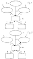
- the method according to the invention can be subdivided into two main steps, in which on the one hand the formation of a forecast model and on the other hand the forecast by the forecast model take place.
- the first main step of the method can be seen from FIG. It is assumed that material data 1 of an input product, material data 2 of an output product and setting or configuration data 3 of a given spinning machine, e.g. a card or a spinning machine for processing the input product.
- a model structure 4 is also specified, which together with model coefficients 5, which still have to be determined with a model formation process 6a, result in a usable process model 6.
- material data 1 include the fiber length, the fiber diameter and the type and quantitative distribution of nits and impurities, etc.
- a typical starting product can be a yarn, for example, which is determined by material data 2 such as its fineness, its uniformity, its tear strength, the frequency of yarn defects and nits, etc.
- the setting data include, for example, the drawing of the roving, the rotation of the yarn or the speed of the spindle or the rotor.
- configuration data the type of carding with card and cover and the relevant distances can be mentioned, etc.
- the model structure 4 is in turn determined by the type and arrangement of basic elements from which the model is constructed.
- the basic elements here are equations which can be implemented in terms of hardware by means of arrangements known per se with simple logic circuits, operational amplifiers, adders, multipliers, etc. Arranging the elements in series, parallel or combined in several layers and the type and number of connections between the elements are to be understood as the arrangement of the elements.
- Such a model structure consists of a system of nonlinear, at least approximately similar equations, which is commonly referred to as a neural network.
- Coefficients are to be understood as quantities or sets of numbers that can be assigned or added to the equations or elements in the model structure and that influence the behavior of the individual elements and thus the model.
- the model structure and the coefficients together form the model or process model.
- the process model is thus formed by specifying a model structure 4, specifying material data 1 of the input product, material data 2 of the output product and configuration and setting data 3 of the machine or the processing, and determining coefficients that cause a reproducible relationship between data sets of the material data 1 and 2 and the configuration data 3 arises. For this, given Data sets of material and configuration data as initial values, the coefficients specified until the relationship is correct, that is, until when the material data 1 of the input product and the configuration and setting data 3 are input, the material data 2 of the output product can be output with good approximation by the process model.
- the coefficients determined in this way are then an integral part of the process model, are expressed in the setting of its elements or are stored in a database which is known per se and which can be passed on to the elements at any time as required.
- the processes just described are further illustrated by arrows 7 to 11, which indicate a specific direction for the flow of data and specifications.
- the arrows 7 to 10 are directed against the model formation process 6a and thus indicate that material data, configuration and setting data and the model structure for this step are predefined from the outside. From this, useful coefficients are to be obtained, which is indicated by the direction of arrow 11, because it indicates the result.
- the second main step of the method can be seen from FIG.
- the same elements known from FIG. 1 are provided with the same reference numerals.
- the arrows 8 and 11 point in the opposite direction and thus indicate that the coefficients are now known and thus given and that material data 2 of starting products can be sought, for example.
- this step is only an example, because it is equally conceivable with this step to search for known material data 1 and 2 configuration data from the known process model, or material data 1 of the input product from the material data 2 and the configuration and setting data 3.
- the configuration and setting data 3 in this step could also be hypothetical processing data, that is, setting data of a machine that does not really exist. This could be used to determine how such a hypothetical machine works. In such cases, relevant data do not appear as individual data or as individual values, but rather in groups or as data sets that characterize products or machines.
- FIG. 3 shows a schematic representation of a structure of a model as it is designated by the reference number 4 in FIGS. 1 and 2.
- the model 6 consists of individual equations or elements 12a to 12n of a first layer 12 which are at least approximately the same, elements 13a to 13n of a second layer 13 and elements 14a to 14n of a further layer 14. All elements are of the first layer 12 via connections 15 to all elements of the second layer 13 and these in turn connected to all elements of the further layer 14 via connections 16.
- the elements 12a to 12n of the first layer 12 have inputs 17a to 17n for a group of material data 1 of an input product and for configuration and setting data of a spinning machine.
- the elements 14a to 14n of the further layer 14 have inputs 18a to 18n for a group of material data 2. All of these elements 12a to 12n, 13a to 13n and 14a to 14n, when the model 6 is operating in the learning mode, receive coefficients which weight the data in the connections 15 and 16.
- FIG. 4 shows the model according to FIG. 3 when it works in the forecast mode.
- this consists in that, starting from input values 1 for material data and configuration and setting data 3, which are input via inputs 17a to 17n, output values for material data 2 of an output product are output via outputs 18a to 18n.
- outputs 18a to 18n With 18a to 18n, depending on the working method of the model, inputs are designated in one case and outputs for data in the other.
- FIGS. 3 and 4 are known to the experts as so-called neural networks and, for example, from R. Lippmann "An Introduction to Computing with Neural Nets", IEEE, Acoustics, Speech and Signal Processing Magazine, April 1987, pages 4 - 22 known.
- FIG. 5 shows, for example, the structure of an equation or an element 12, 13 or 14 from FIGS. 3 and 4 as it could be implemented in traditional electronics.
- an element consists of an operational amplifier 40, with a feedback 41.
- the operational amplifier 40 has one or more inputs 42a to 42n and an output 43, which opens into a downstream element 44, which can be designed as a filter, distortion or limiter, etc.
- the operational amplifier 40 is also connected to a feed line 45.
- the gain is determined by the resistor 46 of the feedback 41 and by series resistors W1, W2, Wn etc. which are assigned to the individual inputs 42a, 42b 42n.
- series resistors W1 to Wn are adjustable, so that the gain of the element 12, 13, 14 can be adjusted with respect to the individual inputs.
- the setting of the gain corresponds to what was previously referred to as setting the coefficients.
- the series resistors can be connected, for example, to a computer or to a coefficient generator, by means of which these series resistors W1, Wn can also be set individually by automated input of values.
- Figure 6 shows an element 12, 13, 14 again in a schematic representation with the formula for its transfer function.
- the input values x, W the values of the series resistors or the coefficients, and theta a constant.
- FIGS. 7, 8 and 9 each show a typical example of a transfer function which could be implemented by a limiter 44, u being the input values and f (u) being the output values.
- FIGS. 3 to 6 The structure shown in FIGS. 3 to 6 with the elements does not have to be constructed from discrete elements in the manner shown. It can just as well be implemented by a computer, the program of which functionally simulates such a structure.
- FIG. 10 again shows schematically a process model 6 'of a first spinning machine and a process model 6''of a further spinning machine, which are formed independently of one another in a known manner.
- the process models can then be connected to one another by using at least some of the output data 18 'of the first process model 6' as input data 17 'of the further process model 6''can be used, each process model being supplied with its own data about the configuration and the setting parameters.
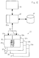
- FIG. 11 shows schematically known processing operations 20, such as those which take place, for example, on cards, spinning machines, etc.
- Several processing runs here in parallel so that several machines 21, 22, 23, 24 etc. arranged in parallel are shown schematically, all of which a controller 21a, 22a, 23a, 24a etc. and a device 21b, 22b, 23b, 24b for Show feedback of data.
- the controls 21a to 24a are designed in particular to execute control commands which they can receive from a computer 26 or a database 27.
- the devices 21b to 24b are designed, for example, as sensors which report the setting and status values of the machines 21 to 24. These can be, for example, tachometers, pressure sensors, etc. with their evaluation circuits.
- Machines in this sense are, for example, cards, ring spinning machines, rotor spinning machines, etc., or spinning machines in general, all of which have their own control and device for monitoring or reporting data for various parameters. All of these machines 21 to 24 are connected to one another via a fieldbus 25 and additionally to a computer 26 as a processing unit, which in turn is connected to a data memory with a database 27 stored therein and to an input and output unit 28 for data.
- the processing unit is designed as a computer 26 with an associated program memory 26a and serves to receive data from the machines 21 etc. or to deliver data to them.
- This processing unit can in particular also be used or designed to collect input variables, output variables and setting variables of the individual machines and to relate them to one another and to store corresponding data records in the database 27.
- a comparable arrangement as shown in FIG. 11 for a production process can be found in FIG. 12 for a textile test laboratory.
- Various tests 29 can be carried out in the test laboratory.
- a first test instrument 30 is designed, for example, to test the cross section and mass of yarns.
- a second test instrument 31 is designed, for example, for testing nonwovens or tapes.
- a third test instrument 32 is designed for measuring different sizes on individual fibers.
- Another test instrument 33 is designed, for example, to test the tensile strength of yarns, etc. All test instruments 30 to 33 have their own control 30a to 33a and their own data memory 30b to 33b.
- the controls 30a to 33a for example, issue control commands in the sense of orders to the actual test instruments 30a to 33a.
- the data memories 30b to 33b have stored measurement results, for example.
- the test instruments 30 to 33 are connected to a common fieldbus 34, which in turn is connected to a processing unit 35, via the controls and the data memories.
- This is constructed as a computer with a program memory 35a. As already known, this is also connected to an input and output unit 36 and a data memory with a database 37 stored therein. It is possible to provide a single and common processing unit 26 or 35 for one or more spinning machines 21 to 24 and measuring devices or test instruments 30 to 33 spatially separated therefrom. However, it is also conceivable to assign a computer to each spinning machine 21 to 24, which, for example, can be part of the control 21a to 24a and can operate in the sense of a processing unit in the aforementioned sense.
- the fieldbus 25 works as a means of moving the data between these computers.
- the databases 27 and / or 37 have an area with stored coefficients that can be fed to the computer 26 and / or 35 and thus can build up the model structure for the process model stored in the program memory 26a, 35a. Even if the test instruments 30 to 33 could each be provided with their own computer, it still makes sense to provide a common computer 35, as shown in FIG. 12. This is because the construction of a coefficient matrix according to the back propagation method requires a lot of computation requires that exceeds the capabilities of a single computer as it is assigned to a test instrument.
- the test laboratory is loaded with random samples that originate from the production process. The samples are taken before, between and at the end of each processing or machine. By testing the random samples, the success in the individual processing operations in the test laboratory can be measured.
- Through the networking of the individual test instruments 30, 31, 32, 33, etc. via the fieldbus 34 and the processing unit 35 input data and output data of the material from the corresponding tests can be recorded and in for each processing or machine 21, 22, 23, 24 etc. the database 37 are stored.
- the configuration and setting data of the machines 21, 22, 23, 24, etc. in question can be stored in the database 27 via the processing unit 26. In this way, all data for the creation of a model can be collected and stored in an orderly manner so that it can be called up.
- FIG. 13 shows, in particular, a schematic representation of the two databases 27 and 37, which are connected to a filter 50 implemented in software in the sense that the content of both databases 27 and 37 can be supplied to this filter at least temporarily.
- the filter 50 ensures that the material input and output data corresponding to one another are combined with the corresponding data of the machine or processing which has brought about the change in the material readable from the output data with the input data.
- output data relating to yarn fineness and yarn uniformity are to be related to setting data of a spinning machine and input data of a nonwoven or belt.
- various types of data must be merged, which are listed, for example, in field 51.
- This is divided into a field 52 for identification data, a field 53 for machine or configuration data and a field 54 for material data. Accordingly, the data from fields 52 and 53 must be extracted from database 27 and the data from fields 52 and 54 must be extracted from database 37. This takes place, for example, in one of the processing units 26 or 35, which have a filter 50, which can combine the configuration data and the material data on the basis of the identification data.
- This merging is known per se in database technology and is triggered, for example, in so-called “relational database systems" by the so-called "join command".
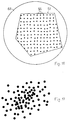
- Model 6 (FIGS. 3 and 4) is all the better and more universally applicable if material and configuration data which are as diverse as possible and which are as complete as possible in their entirety are taken into account when forming the model. If you get this data from an ongoing production, it may be that you only have data available in a narrow area. Such areas 55 and 56 are shown for input data 57 and output data 58 in FIG. 14. In such cases, it can be advantageous to determine data derived therefrom, for example by averaging the input data to an average value 59 and the output data to an average value 60, as shown in FIG. This is particularly useful if the input and output data do not exactly match due to statistical fluctuations. If this is the case, the modeling can be accelerated because there is only one data record at a time. This is indicated by a single arrow 61.
- each point 62, 63, 64 etc. represents a data record or a group of data records
- the above-mentioned averaging can be advantageous for areas 65 or parts of these areas where data is accumulated occur. This then leads to a diluted data record, as shown in FIG. 17.
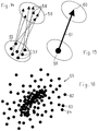
- the experiences that are brought into the model via the data can be very different. They can extend over a large range of material data and configuration and setting data, as indicated by points 66 in an area 67 in FIG. 18. In addition, there will always be an area 68 outside of area 67 for which the experiences of the model do not apply because they are not supported by any experiences because there was no data available.
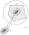
- FIG. 19 shows, there can also be a partial area 69 with particularly great experience within a area 70 with average experience.
- the process model is formed on the basis of data from a partial area 69 of the area 70. This can e.g. also mean that the greater experience was later brought into area 70.
- such models can help inexperienced people to favorably influence a production process.
- Experienced people are given the opportunity to deepen the experience.
Landscapes
- Engineering & Computer Science (AREA)
- Physics & Mathematics (AREA)
- General Physics & Mathematics (AREA)
- Automation & Control Theory (AREA)
- Artificial Intelligence (AREA)
- Evolutionary Computation (AREA)
- Health & Medical Sciences (AREA)
- Computer Vision & Pattern Recognition (AREA)
- Medical Informatics (AREA)
- Software Systems (AREA)
- General Engineering & Computer Science (AREA)
- Manufacturing & Machinery (AREA)
- Quality & Reliability (AREA)
- Spinning Or Twisting Of Yarns (AREA)
Abstract
Description
Die Erfindung betrifft ein Verfahren und eine Vorrichtung zur Voraussage von Eigenschaften von Produkten eines textilen Verarbeitungsprozesses aufgrund eines Prozessmodells, ausgehend von Materialeigenschaften, die das zur Verarbeitung bestimmte Eingangsprodukt betreffen sowie von Konfigurations- und Einstellgrössen, die den Verlauf des Verarbeitungsprozesses beeinflussen.The invention relates to a method and a device for predicting properties of products of a textile processing process based on a process model, starting from material properties that relate to the input product intended for processing and from configuration and setting variables that influence the course of the processing process.
Aus der europäischen Patentanmeldung Nr. 93120587.6 (Shofner et al) ist ein Verfahren zur optimalen Steuerung von Textilmaschinen mittels eines Prozessmodells bekannt. Das Verfahren geht davon aus, dass das Prozessmodell als System von linearen mathematischen Gleichungen dargestellt wird, deren Koeffizienten mittels des Verfahrens der mehrfachen linearen Regression aufgrund von Resultaten aus systematisch durchgeführten Versuchen ermittelt werden.From European patent application No. 93120587.6 (Shofner et al) a method for optimal control of textile machines by means of a process model is known. The method assumes that the process model is represented as a system of linear mathematical equations, the coefficients of which are determined using the method of multiple linear regression on the basis of results from systematically carried out experiments.
Ein Nachteil dieses Verfahrens besteht darin, dass die Einschränkungen, die durch die Voraussetzung eines lineares Gleichungssystems als Prozessmodell geschaffen werden, den praktischen Anforderungen an die Genauigkeit der Nachbildung eines Prozesses durch ein solches Prozessmodell vielfach nicht genügen. Da die funktionellen Zusammenhänge zwischen Eingangsdaten, Ausgangsdaten sowie Konfigurations- und Einstellparametern eines Prozesses in der Regel nicht linear sind, erbringt die Nachbildung eines Prozesses mittels eines linearen Modells höchstens in einem engen Betriebsbereich einigermassen brauchbare Resultate.A disadvantage of this method is that the restrictions created by the requirement of a linear system of equations as a process model often do not meet the practical requirements for the accuracy of the simulation of a process by such a process model. Since the functional relationships between input data, output data, and configuration and setting parameters of a process are generally not linear, the simulation of a process using a linear model only achieves reasonably useful results in a narrow operating range.
Ein weiterer Nachteil dieses Verfahrens besteht darin, dass die praktische Durchführung des Verfahrens der mehrfachen linearen Regression zur Ermittlung der Koeffizienten der Gleichungen eines linearen Gleichungssystems ein sehr gutes mathematisches Verständnis seitens der ausführenden Person erfordert, wenn trotz der genannten grundsätzlichen Einschränkungen ein möglichst praxistaugliches Modell zu erstellen ist.Another disadvantage of this method is that the practical implementation of the multiple linear regression method to determine the coefficients of the equations of a linear system of equations requires a very good mathematical understanding on the part of the person performing it if, despite the fundamental limitations mentioned, a model that is as practical as possible is to be created.
Es ist die Aufgabe der Erfindung, wie sie in den Patentansprüchen gekennzeichnet ist, ein Verfahren und eine Vorrichtung zu schaffen, mit denen anhand eines Prozessmodells zuverlässige Voraussagen über die Wechselwirkungen von Eingangsgrössen, Ausgangsgrössen und Einstellgrössen in der Verarbeitung von textilen Gebilden ohne die vorstehend genannten Nachteile möglich gemacht werden.It is the object of the invention, as characterized in the patent claims, to provide a method and a device with which, on the basis of a process model, reliable predictions about the interactions of input variables, output variables and setting variables in the processing of textile structures without the disadvantages mentioned above be made possible.
Die genannte Aufgabe wird dadurch gelöst, dass die Beziehungen zwischen den Eingangsgrössen, den Ausgangsgrössen und den Konfigurations- und Einstellgrössen durch ein gemeinhin als neuronales Netz bezeichnetes regelmässiges System von nicht linearen, unter sich mindestens annähernd gleichartigen Gleichungen vorgegeben werden.The stated object is achieved in that the relationships between the input variables, the output variables and the configuration and setting variables are predetermined by a regular system, commonly referred to as a neural network, of non-linear, at least approximately similar equations.
Die genannte Aufgabe wird ferner dadurch gelöst, dass die Koeffizienten, die die strukturell definierten Gleichungen eines solchen neuronalen Netzes ausprägen, mittels eines Algorithmus des als "Backpropagation" bekannten sogenannten "Trainings-Verfahrens" für neuronale Netze aufgrund von Resultaten aus systematisch durchgeführten Versuchen ermittelt werden.The above-mentioned object is further achieved in that the coefficients which characterize the structurally defined equations of such a neural network are determined by means of an algorithm of the so-called "training method" known as "back propagation" for neural networks on the basis of results from systematically carried out experiments .
Die genannte Aufgabe wird ferner dadurch gelöst, dass ein gegebenes Grundmodell im Bereich der spezifischen Erfahrung eines Spinnereibetriebes mit einfachen Mitteln so angepasst werden kann, dass es im Bereich dieser spezifischen Erfahrung eben diese wiedergibt.The stated object is also achieved in that a given basic model in the area of the specific experience of a spinning mill can be adapted with simple means in such a way that it reproduces this area in the area of this specific experience.
Die genannte Aufgabe wird ferner dadurch gelöst, dass mindestens eine Spinnereimaschine mit Messeinrichtungen zur Ermittlung der Eingangsgrössen, mit einem Rechner mit einer Ein- und Ausgabeeinheit für Daten, mit Mitteln für die Übertragung von Daten und Signalen zwischen dem Rechner und den Messeinrichtungen, mit einem Programmspeicher im Rechner mit einer Modellstruktur, die ein neuronales Netz darstellt und mit einem Datenspeicher mit Daten über die Eingangsprodukte, die Ausgangsprodukte und Konfigurations-und Einstellparameter vorgesehen wird.The stated object is further achieved in that at least one spinning machine with measuring devices for determining the input variables, with a computer with an input and output unit for data, with means for the transmission of data and signals between the computer and the measuring devices, with a program memory in the computer with a model structure that represents a neural network and is provided with a data memory with data about the input products, the output products and configuration and setting parameters.
Daraus ergeben sich wesentliche Vorteile, die beispielsweise darin bestehen, dass das Prozessmodell wegen der grossen Anpassungsfähigkeit eines neuronalen Netztes an nichtlineare Eigenschaften eines zu modellierenden Prozesses in einem grösseren Bereich mit guter Genauigkeit an das effektive Verhalten eines solchen Prozesses angepasst werden kann.This results in significant advantages, which consist, for example, in the fact that the process model can be adapted to the effective behavior of such a process with good accuracy over a large area due to the great adaptability of a neural network to nonlinear properties of a process to be modeled.
Ein weiterer Vorteil besteht darin, dass wegen der grossen Anpassungsfähigkeit eines neuronalen Netztes an nichtlineare Eigenschaften eines zu modellierenden Prozesses bei der Ermittlung der Koeffizienten, welche die dem Modell zugrunde liegenden Gleichungen ausprägen, keine spezifischen mathematischen Kenntnisse und/oder Einsichten in die mathematischen Verhältnisse notwendig sind und die dazu benötigten Verrichtungen auch von nicht speziell mathematisch geschultem Personal vorgenommen werden können.Another advantage is that due to the great adaptability of a neural network to nonlinear properties of a process to be modeled, no specific mathematical knowledge and / or insights into the mathematical relationships are necessary when determining the coefficients that characterize the equations on which the model is based and the operations required for this can also be carried out by personnel who are not specially mathematically trained.
Ein weiterer Vorteil besteht darin, dass auf diese Weise nicht nur Voraussagen über geschlossene, also einheitliche Verarbeitungen wie z. B. ein Spinnprozess aus dem ein Garn hervorgeht, gemacht werden können. Es können genau so gut zwei oder mehr Verarbeitungen, die hinter einander erfolgen, gemeinsam in ein kombiniertes Prozessmodell eingebracht werden. Dies auch dann, wenn in diesen Verarbeitungen Prozesse ablaufen, die sich durch ausgeprägte Nichtlinearitäten auszeichnenAnother advantage is that in this way not only predictions about closed, i.e. uniform processing such. B. a spinning process from which a yarn emerges can be made. It is just as good that two or more processes that take place one after the other can be brought together in a combined process model. This also applies to processes that are characterized by pronounced non-linearities
Im folgenden wird die Erfindung anhand eines Beispiels und mit Bezug auf die beiliegenden Figuren näher erläutert, wobei
Figur 1 und 2 je ein Verfahren schematisch,Figur 3 und 4 schematisch je eine Struktur eines Elementes für das Verfahren,Figur 5 eine Ausführungsform eines Elementes der Struktur,Figur 6 dieselbe Struktur nochmals schematisiert,Figur Figur 10 eine kombinierte Struktur eines Prozessmodells,Figur 11 und 12 je ein Schema einer Einrichtung Verarbeitung von Produkten und einer Einrichtung zur Gewinnung von Daten,Figur 13 schematisch einen Teil der Gewinnung von Daten,Figur - Figur 18 und 19 verschiedene Verteilungen der auftretenden Daten darstellen.
- 1 and 2 each schematically a process,
- FIGS. 3 and 4 schematically each show a structure of an element for the method,
- FIG. 5 shows an embodiment of an element of the structure,
- FIG. 6 shows the same structure again,
- FIGS. 7, 8 and 9 each have a transfer function,
- FIG. 10 shows a combined structure of a process model,
- FIGS. 11 and 12 each show a diagram of a device for processing products and a device for obtaining data,
- FIG. 13 schematically shows part of the data acquisition,
- Figure 14, 15, 16 and 17 schematically possible situations in the acquisition of data and
- Figures 18 and 19 show different distributions of the data occurring.
Das erfindungsgemässe Verfahren kann in zwei Hauptschritte unterteilt werden in denen einerseits die Bildung eines Prognosemodells und andererseits die Prognose durch das Prognosemodell stattfinden.The method according to the invention can be subdivided into two main steps, in which on the one hand the formation of a forecast model and on the other hand the forecast by the forecast model take place.
Aus Figur 1 ist der erste Hauptschritt des Verfahrens erkennbar. Man geht davon aus, dass in einem Bereiche messtechnisch erfasste Materialdaten 1 eines Eingangsproduktes, Materialdaten 2 eines Ausgangsproduktes und Einstell- oder Konfigurationsdaten 3 einer vorgegebenen Spinnereimaschine z.B. einer Karde oder einer Spinnmaschine, zur Verarbeitung des Eingangsproduktes vorliegen. Ebenfalls vorgegeben wird eine Modellstruktur 4, die zusammen mit Modellkoeffizienten 5, die mit einem Modellbildungsprozess 6a noch zu bestimmen sind, ein brauchbares Prozessmodell 6 ergeben.The first main step of the method can be seen from FIG. It is assumed that
Als Eingangsprodukte sind beispielsweise Fasern, Vorgarne oder andere Produkte zu nennen, aus denen ein Garn entstehen soll. Demnach sind als typische Beispiele von Materialdaten 1 die Faserlänge, der Faserdurchmesser und Art und mengenmässige Verteilung von Nissen und Verunreinigungen usw. zu nennen.For example, fibers, rovings or other products from which a yarn is to be made can be mentioned as input products. Accordingly, typical examples of
Ein typisches Ausgangsprodukt kann beispielsweise ein Garn sein, das durch Materialdaten 2 wie seine Feinheit, seine Gleichmässigkeit, seine Reissfestigkeit, die Häufigkeit von Garnfehlern und Nissen usw. bestimmt ist.A typical starting product can be a yarn, for example, which is determined by
Als Einstelldaten sind beispielsweise für eine Spinnmaschine die Verstreckung des Vorgarns, die Drehung des Garns oder die Drehzahl der Spindel oder des Rotors zu nennen. Als Beispiel für Konfigurationsdaten kann die Art der Bestückung einer Karde mit Garnitur und Deckel und die dabei relevanten Abstände genannt werden usw.For a spinning machine, the setting data include, for example, the drawing of the roving, the rotation of the yarn or the speed of the spindle or the rotor. As an example of configuration data, the type of carding with card and cover and the relevant distances can be mentioned, etc.
Die Modellstruktur 4 wiederum ist durch die Art und die Anordnung von Grundelementen bestimmt, aus denen das Modell aufgebaut ist. Als Grundelemente kommen hier Gleichungen in Frage, die durch an sich bekannte Anordnungen mit einfachen logischen Schaltkreisen, Operationsvertärkern, Addierern, Multiplizierern usw. hardwaremässig realisiert werden können. Als Anordnung der Elemente ist deren Schaltung in Serie, parallel oder kombiniert in mehreren Schichten sowie die Art und Zahl der Verbindungen zwischen den Elementen zu verstehen. Eine solche Modellstruktur besteht aus einem System von nichtlinearen, unter sich mindestens annähernd gleichartigen Gleichungen was man gemeinhin als neuronales Netz bezeichnet.The
Als Koeffizienten sind Grössen oder Zahlensätze zu verstehen, die den Gleichungen oder Elementen in der Modellstruktur zugeordnet oder zugeführt werden können und die das Verhalten der einzelnen Elemente und damit des Modells beeinflussen. Die Modellstruktur und die Koeffizienten bilden zusammen das Modell oder Prozessmodell.Coefficients are to be understood as quantities or sets of numbers that can be assigned or added to the equations or elements in the model structure and that influence the behavior of the individual elements and thus the model. The model structure and the coefficients together form the model or process model.
Das Prozessmodell wird somit gebildet, indem eine Modellstruktur 4 vorgegeben, Materialdaten 1 des Eingangsproduktes, Materialdaten 2 des Ausgangsproduktes und Konfigurations- und Einstelldaten 3 der Maschine oder der Verarbeitung vorgegeben und indem Koeffizienten ermittelt werden, die bewirken, dass eine reproduzierbare Beziehung zwischen Datensätzen der Materialdaten 1 und 2 und den Konfigurationsdaten 3 entsteht. Dazu werden bei gegebenen Datensätzen von Material- und Konfigurationsdaten als Startwerte vorgegebene Koeffizienten solange variiert bis die Beziehung stimmt, d.h. bis bei einer Eingabe der Materialdaten 1 des Eingangsproduktes und der Konfigurations- und Einstelldaten 3, die Materialdaten 2 des Ausgangsproduktes durch das Prozessmodell mit guter Näherung ausgegeben werden können. Die so ermittelten Koeffizienten sind dann fester Bestandteil des Prozessmodells, äussern sich darin in der Einstellung seiner Elemente oder sind in einer an sich bekannten Datenbank gespeichert, die diese nach Bedarf jederzeit an die Elemente abgeben kann. Die eben beschriebenen Vorgänge sind weiter durch Pfeile 7 bis 11 verdeutlicht, die eine bestimmte Richtung für den Fluss der Daten und Vorgaben angeben. Die Pfeile 7 bis 10 sind gegen den Modellbildungsprozess 6a gerichtet und deuten damit an, dass Materialdaten, Konfigurations- und Einstelldaten und die Modellstruktur für diesen Schritt von aussen vorgegeben werden. Daraus sollen brauchbare Koeffizienten gewonnen werden, was durch die Richtung des Pfeiles 11 angedeutet ist, denn er weist auf das Resultat hin.The process model is thus formed by specifying a
Aus Figur 2 ist der zweite Hauptschritt des Verfahrens erkennbar. Darin sind gleiche und aus der Fig. 1 bekannte Elemente mit gleichen Bezugszeichen versehen. Die Pfeile 8 und 11 weisen in die entgegengesetzte Richtung und deuten damit an, dass die Koeffizienten nun bekannt und damit gegeben sind und dass beispielsweise Materialdaten 2 von Ausgangsprodukten gesucht sein können. Dies ist aber nur ein Beispiel, denn es ist ebensogut denkbar mit diesem Schritt aus dem bekannten Prozessmodell nun für bekannte Materialdaten 1 und 2 Konfigurationsdaten, oder aus den Materialdaten 2 und den Konfigurations- und Einstelldaten 3, Materialdaten 1 des Eingangsproduktes zu suchen. Es ist weiter anzufügen, dass die Konfigurations- und Einstelldaten 3 in diesem Schritt ebenso Daten einer hypothetischen Verarbeitung sein könnten, also Einstelldaten einer Maschine die nicht wirklich existiert. Damit könnte die Arbeitsweise einer solchen hypothetischen Maschine ermittelt werden. Relevante Daten treten in solchen Fällen nicht als Einzeldaten oder als einzelne Werte sondern in Gruppen oder als Datensätze auf, die Produkte oder Maschinen charakterisieren.The second main step of the method can be seen from FIG. The same elements known from FIG. 1 are provided with the same reference numerals. The
Figur 3 zeigt in schematischer Darstellung eine Struktur eines Modells wie sie in den Figuren 1 und 2 mit dem Bezugszeichen 4 bezeichnet ist. Das Modell 6 besteht aus einzelnen unter sich mindestens annähernd gleichen Gleichungen oder Elementen 12a bis 12n einer ersten Schicht 12, aus ebensolchen Elementen 13a bis 13n einer zweiten Schicht 13 und aus Elementen 14a bis 14n einer weiteren Schicht 14. Dabei sind alle Elemente der ersten Schicht 12 über Verbindungen 15 mit allen Elementen der zweiten Schicht 13 und diese wiederum mit allen Elementen der weiteren Schicht 14 über Verbindungen 16 verbunden. Die Elemente 12a bis 12n der ersten Schicht 12 weisen Eingänge 17a bis 17n für eine Gruppe von Materialdaten 1 eines Eingangsproduktes und für Konfigurations- und Einstelldaten einer spinnereimaschine auf. Die Elemente 14a bis 14n der weiteren Schicht 14 weisen Eingänge 18a bis 18n für eine Gruppe von Materialdaten 2 auf. Alle diese Elemente 12a bis 12n, 13a bis 13n und 14a bis 14n erhalten, wenn das Modell 6 im Lernmodus arbeitet, Koeffizienten, die die Daten in den Verbindungen 15 und 16 gewichten.FIG. 3 shows a schematic representation of a structure of a model as it is designated by the
Figur 4 zeigt das Modell gemäss Fig. 3 wenn es im Prognosemodus arbeitet. Dieser besteht in der Regel darin, dass ausgehend von Eingangswerten 1 für Materialdaten und Konfigurations- und Einstelldaten 3, die über die Eingänge 17a bis 17n eingegeben werden, Ausgangswerte für Materialdaten 2 eines Ausgangsproduktes über Ausgänge 18a bis 18n ausgegeben werden. Mit 18a bis 18n sind demnach je nach Arbeitsweise des Modells im einen Falle Eingänge und im anderen Falle Ausgänge für Daten bezeichnet.FIG. 4 shows the model according to FIG. 3 when it works in the forecast mode. As a rule, this consists in that, starting from
Die in den Figuren 3 und 4 dargestellten Modelle oder Modellstrukturen sind der Fachwelt als sogenannte neuronale Netze bekannt und beispielsweise aus R. Lippmann "An Introduction to Computing with Neural Nets", IEEE, Acoustics, Speech and Signal Processing Magazine, April 1987, Seiten 4 - 22 bekannt.The models or model structures shown in FIGS. 3 and 4 are known to the experts as so-called neural networks and, for example, from R. Lippmann "An Introduction to Computing with Neural Nets", IEEE, Acoustics, Speech and Signal Processing Magazine, April 1987, pages 4 - 22 known.
Figur 5 zeigt beispielsweise den Aufbau einer Gleichung oder eines Elementes 12, 13 oder 14 aus den Figuren 3 und 4 wie er in traditioneller Elektronik realisiert werden könnte. In diesem Falle besteht ein solches Element aus einem Operationsverstärker 40, mit einer Rückkopplung 41. Der Operationsverstärker 40 hat einen oder mehrere Eingänge 42a bis 42n und einen Ausgang 43, der in ein nachgeschaltetes Element 44 mündet, das als Filter, Verzerrer oder Begrenzer usw. ausgebildet sein kann. Der Operationsverstärker 40 ist ebenfalls an eine Speiseleitung 45 angeschlossen. Die Verstärkung wird durch den Widerstand 46 der Rückkopplung 41 sowie durch Vorwiderstände W1, W2, Wn usw. bestimmt, die den einzelnen Eingängen 42a, 42b 42n zugeordnet sind. Diese Vorwiderstände W1 bis Wn sind einstellbar, so dass damit die Verstärkung des Elementes 12, 13, 14 in bezug auf die einzelnen Eingänge eingestellt werden kann. Das Einstellen der Verstärkung entspricht hier dem, was bisher als Einstellung der Koeffizienten bezeichnet wurde. Die Vorwiderstände können zu diesem Zweck beispielsweise an einen Rechner oder an einen Koeffizientengenerator angeschlossen sein, durch den diese Vorwiderstände W1, Wn auch durch automatisierte Eingbe von Werten individuell eingestellt werden können.FIG. 5 shows, for example, the structure of an equation or an
Figur 6 zeigt ein Element 12, 13, 14 nochmals in schematischer Darstellung mit der Formel für seine Übertragungsfunktion. Darin sind mit x die Eingangswerte, mit W die Werte der Vorwiderstände oder die Koeffizienten und mit theta eine Konstante bezeichnet.Figure 6 shows an
Die Figuren 7, 8 und 9 zeigen je ein typisches Beispiel einer Übertragungsfunktion, die durch einen Begrenzer 44 realisiert werden könnte, wobei mit u die Eingabewerte und mit f(u) die Ausgabewerte bezeichnet sind.FIGS. 7, 8 and 9 each show a typical example of a transfer function which could be implemented by a
Die in den Figuren 3 bis 6 dargestellte Struktur mit den Elementen muss nicht in der gezeigten Weise aus diskreten Elementen aufgebaut sein. Sie kann ebensogut durch einen Rechner realisiert sein, dessen Programm einen solchen Aufbau funktionsmässig nachbildet.The structure shown in FIGS. 3 to 6 with the elements does not have to be constructed from discrete elements in the manner shown. It can just as well be implemented by a computer, the program of which functionally simulates such a structure.
Figur 10 zeigt wiederum schematisch ein Prozessmodell 6' einer ersten Spinnereimaschine und ein Prozessmodell 6'' einer weiteren Spinnereimaschine die in nun bekannter Weise unabhängig voneinander gebildet werden. Anschliessend können die Prozessmodelle miteinander verbunden werden, indem mindestens ein Teil der Ausgangsdaten 18' des ersten Prozessmodells 6' als Eingangsdaten 17' des weiteren Prozessmodells 6'' verwendet werden, wobei jedem Prozessmodell eigene Daten über die Konfiguration und die Einstellparameter zugeführt werden.FIG. 10 again shows schematically a process model 6 'of a first spinning machine and a process model 6''of a further spinning machine, which are formed independently of one another in a known manner. The process models can then be connected to one another by using at least some of the output data 18 'of the first process model 6' as input data 17 'of the further process model 6''can be used, each process model being supplied with its own data about the configuration and the setting parameters.
Das erfindungsgemässe Verfahren welches die Vorteile der genannten Netze für bestimmte Probleme bei der Verarbeitung von Eingangsprodukten zu Zwischenprodukten oder zu textilen Gebilden nutzt, lässt sich an den weiteren und nachfolgend beschriebenen Figuren darstellen.The method according to the invention, which uses the advantages of the networks mentioned for certain problems in the processing of input products to intermediate products or to textile structures, can be illustrated in the further figures described below.
Figur 11 zeigt schematisch bekannte Verarbeitungen 20 wie sie beispielsweise auf Karden, Spinnmaschinen usw. ablaufen. Mehrere Verarbeitungen laufen hier parallel ab, so dass mehrere parallel angeordnete Maschinen 21, 22, 23, 24 usw. schematisch gezeigt sind, die alle eine Steuerung 21a, 22a, 23a, 24a usw. sowie eine Einrichtung 21b, 22b, 23b, 24b zur Rückmeldung von Daten aufweisen. Die Steuerungen 21a bis 24a sind insbesondere zur Ausführung von Steuerbefehlen, die sie aus einem Rechner 26 oder einer Datenbank 27 erhalten können, ausgebildet. Die Einrichtungen 21b bis 24b sind beispielsweise als Sensoren ausgebildet, die Einstell- und Zustandswerte der Maschinen 21 bis 24 melden. Das können beispielsweise Drehzahlmesser, Druckfühler usw. mit ihren Auswerteschaltungen sein. Als Maschinen in diesem Sinne sind beispielsweise Karden, Ringspinnmaschinen, Rotorspinnmaschinen usw. oder eben allgemein Spinnereimaschinen zu verstehen, die alle ihre eigene Steuerung und Einrichtung zur Überwachung oder Rückmeldung von Daten für verschiedene Parameter haben. Alle diese Maschinen 21 bis 24 sind über einen Feldbus 25 miteinander und zusätzlich mit einem Rechner 26 als Verarbeitungseinheit verbunden, der wiederum an einen Datenspeicher mit darin abgelegter Datenbank 27 und an eine Ein-und Ausgabeeinheit 28 für Daten angeschlossen ist. Die Verarbeitungseinheit ist als Rechner 26 mit zugeordnetem Programmspeicher 26a ausgebildet und dient dazu, von den Maschinen 21 usw. Daten zu empfangen oder Daten an diese abzugeben. Diese Verarbeitungseinheit kann insbesondere auch dazu verwendet werden oder ausgebildet sein, Eingangsgrössen, Ausgangsgrössen und Einstellgrössen der einzelnen Maschinen zu sammeln und miteinander in Beziehung zu bringen und entsprechende Datensätze in der Datenbank 27 abzulegen.FIG. 11 shows schematically known
Eine vergleichbare Anordnung wie sie in Fig. 11 für einen Produktionsprozess dargestellt ist, findet man in der Figur 12 für ein textiles Prüflabor. Im Prüflabor können verschiedene Prüfungen 29 durchgeführt werden. Ein erstes Prüfinstrument 30 ist beispielsweise zur Prüfung von Querschnitt und Masse von Garnen ausgebildet. Ein zweites Prüfinstrument 31 ist beispielsweise zur Prüfung von Vliesen oder Bändern ausgebildet. Ein drittes Prüfinstrument 32 ist für die Messung verschiedener Grössen an einzelnen Fasern ausgebildet. Ein weiteres Prüfinstrument 33 ist beispielsweise zur Prüfung der Reissfestigkeit von Garnen ausgebildet usw. Alle Prüfinstrumente 30 bis 33 haben eine eigene Steuerung 30a bis 33a und einen eigenen Datenspeicher 30b bis 33b. Die Steuerungen 30a bis 33a geben beispielsweise Steuerbefehle im Sinne von Aufträgen an die eigentlichen Prüfinstrumente 30a bis 33a ab. Die Datenspeicher 30b bis 33b haben beispielsweise Messergebnisse gespeichert. Über die Steuerungen und die Datenspeicher sind die Prüfinstrumente 30 bis 33 an einen gemeinsamen Feldbus 34 angeschlossen, der wiederum an eine Verarbeitungseinheit 35 angeschlossen ist. Diese ist als Rechner mit einem Programmspeicher 35a aufgebaut. Wie bereits bekannt, ist diese auch an eine Ein-und Ausgabeeinheit 36 und einen Datenspeicher mit darin abgespeicherter Datenbank 37 angeschlossen. Es ist möglich eine einzige und gemeinsame Verarbeitungseinheit 26 oder 35 für eine oder mehrere Spinnereimaschinen 21 bis 24 und davon räumlich getrennte Messeinrichtungen oder Prüfinstrumente 30 bis 33 vorzusehen. Es ist aber auch denkbar, jeder Spinnereimaschine 21 bis 24 einen Rechner zuzuordnen, der beispielsweise Teil der Steuerung 21a bis 24a sein und im Sinne einer Verarbeitungseinheit im obengenannten Sinne arbeiten kann. Dann arbeitet der Feldbus 25 als Mittel zum Verschieben der Daten zwischen diesen Rechnern. Die Datenbanken 27 und/oder 37 weisen einen Bereich mit gespeicherten Koeffizienten auf, die dem Rechner 26 und/oder 35 zugeführt werden können und so die im Programmspeicher 26a, 35a gespeicherte Modellstruktur zum Prozessmodell aufbauen können. Auch wenn man die Prüfinstrumente 30 bis 33 mit je einem eignen Rechner versehen könnte, so ist es doch sinnvoll, einen gemeinsamen Rechner 35, wie in Fig. 12 gezeigt, vorzusehen. Dies, weil der Aufbau einer Koeffizientenmatrix nach dem Back-Propagation-Verfahren einen hohen Rechenaufwand erfordert, der die Möglichkeiten eines einzelnen Rechners, wie er einem Prüfinstrument zugeordnet ist, übersteigt.A comparable arrangement as shown in FIG. 11 for a production process can be found in FIG. 12 for a textile test laboratory.
Zwischen einem Textilprüflabor, das wie in Fig. 12 dargestellt aufgebaut sein kann und einem Produktionsprozess oder einer Produktionsanlage, die beispielsweise wie in Fig. 11 dargestellt aufgebaut sein kann, besteht der nachfolgend beschriebene Zusammenhang und damit sind auch die nachfolgend beschriebenen Wechselwirkungen möglich.The relationship described below exists between a textile testing laboratory, which can be constructed as shown in FIG. 12, and a production process or a production plant, which can be constructed, for example, as shown in FIG. 11, and the interactions described below are therefore also possible.
Das Prüflabor wird mit Stichproben beschickt, die aus dem Produktionsprozess stammen. Die Stichproben werden vor, zwischen und am Ende der einzelnen Verarbeitungen oder Maschinen entnommen. Durch Prüfung der Stichproben ist der Erfolg in den einzelnen Verarbeitungen im Prüflabor messbar. Durch die Vernetzung der einzelnen Prüfinstrumente 30, 31, 32, 33 usw. über den Feldbus 34 und die Verarbeitungseinheit 35 können für jede Verarbeitung oder Maschine 21, 22, 23, 24 usw. Eingangsdaten und Ausgangsdaten des Materials aus den entsprechenden Prüfungen erfasst und in der Datenbank 37 abgelegt werden. Durch die entsprechende Vernetzung der Maschinen 21, 22, 23, 24 usw. über den Feldbus 25 können die Konfigurations- und Einstelldaten der betreffenden Maschinen 21, 22, 23, 24, usw. über die Verarbeitungseinheit 26 in der Datenbank 27 abgelegt werden. So können alle Daten für die Erstellung eines Modells gesammelt und geordnet gespeichert werden, so dass diese abrufbar sind. Durch geeignetes Zusammenführen der betreffenden Daten aus den beiden Datenbanken 27 und 37 kann dafür gesorgt werden, dass auch die richtigen Daten kombiniert werden. Dies wird mit der Darstellung in Fig. 13 gezeigt. Dies beispielsweise dadurch, dass der Feldbus 25 der Spinnereimaschinen 21 bis 24 und der Feldbus 34 der Prüfinstrumente 30 bis 33 identisch definiert und miteinander verbunden werden.The test laboratory is loaded with random samples that originate from the production process. The samples are taken before, between and at the end of each processing or machine. By testing the random samples, the success in the individual processing operations in the test laboratory can be measured. Through the networking of the
Figur 13 zeigt insbesondere in schematischer Darstellung die beiden Datenbanken 27 und 37, die in dem Sinne an ein softwaremässig realisiertes Filter 50 angeschlossen sind, als der Inhalt beider Datenbanken 27 und 37 diesem Filter wenigstens zeitweise zugeführt werden kann. Im Filter 50 wird dafür gesorgt, dass die einander entsprechenden Material-Ein-und Ausgangsdaten mit den entsprechenden Daten derjenigen Maschine oder Verarbeitung zusammengeführt werden, die die an den Ausgangsdaten ablesbare Veränderung am Material mit den Eingangsdaten herbeigeführt hat. Beispielsweise sollen Ausgangsdaten, die die Garnfeinheit und die Garngleichmässigkeit betreffen zu Einstelldaten einer Spinnmaschine und zu Eingangsdaten eines Vlieses oder Bandes in Beziehung gebracht werden. Damit dies gelingt, müssen verschiedenartige Daten zusammengeführt werden, die beispielsweise im Feld 51 aufgeführt sind. Dieses ist unterteilt in ein Feld 52 für Identifikationsdaten, ein Feld 53 für Maschinen- oder Konfigurationsdaten und ein Feld 54 für Materialdaten. Aus der Datenbank 27 müssen demnach die Daten aus den Feldern 52 und 53 herausgezogen und aus der Datenbank 37 müssen die Daten aus den Feldern 52 und 54 herausgezogen werden. Dies geschieht beispielsweise in einer der Verarbeitungseinheiten 26 oder 35, die über ein Filter 50 verfügen, das anhand der Identifikationsdaten die Konfigurationsdaten und die Materialdaten zusammenführen kann. Dieses Zusammenführen ist in der Datenbanktechnik an sich bekannt und wird beispielsweise bei sogenannten "relationalen Datenbankensystemen" durch den sogenannten "Join-Befehl" ausgelöst.FIG. 13 shows, in particular, a schematic representation of the two
Das Modell 6 (Fig. 3 und 4) ist umso besser und universaler anwendbar, wenn möglichst verschiedenartige und in ihrer Gesamtheit möglichst vollständige experimentell ermittelte Material-und Konfigurationsdaten bei der Modellbildung berücksichtigt wurden. Holt man diese Daten aus einer laufenden Produktion, so kann es sein, dass man nur in einem engen Bereich gelegene Daten zur Verfügung hat. Solche Bereiche 55 und 56 sind für Eingangsdaten 57 und Ausgangsdaten 58 in der Figur 14 gezeigt. In solchen Fällen kann es vorteilhaft sein davon abgeleitete Daten zu ermitteln, beispielsweise indem die Eingangsdaten zu einem Mittelwert 59 und die Ausgangsdaten zu einem Mittelwert 60 gemitttelt werden, wie dies in der Figur 15 gezeigt ist. Dies ist insbesondere dann sinnvoll, wenn die Ein- und die Ausgangsdaten lediglich wegen statistischer Schwankungen nicht genau übereinstimmen. Wenn das der Fall ist, kann die Modellbildung beschleunigt erfolgen, denn es ist jeweils nur ein Datensatz vorhanden. Dies ist durch einen einzigen Pfeil 61 angedeutet.Model 6 (FIGS. 3 and 4) is all the better and more universally applicable if material and configuration data which are as diverse as possible and which are as complete as possible in their entirety are taken into account when forming the model. If you get this data from an ongoing production, it may be that you only have data available in a narrow area.
Liegen Datensätze vor, wie sie in der Figur 16 gezeigt sind, wo jeder Punkt 62, 63, 64 usw. einen Datensatz oder eine Gruppe von Datensätzen darstellt, so kann die obengenannte Mittelung für Bereiche 65 oder Teile dieser Bereiche vorteilhaft sein, wo Daten gehäuft auftreten. Dies führt dann zu einem verdünnten Datensatz, wie er in der Figur 17 dargestellt ist.If there are data records as shown in FIG. 16, where each
Die Erfahrungen, die über die Daten in das Modell eingebracht sind, können sehr verschiedenartig sein. Sie können sich über einen grossen Bereich von Materialdaten und Konfigurations- und Einstelldaten erstrecken, so wie dies Punkte 66 in einem Bereich 67 in der Figur 18 andeuten. Darüberhinaus wird es immer auch ein Gebiet 68 ausserhalb des Gebietes 67 geben für das die Erfahrungen des Modells nicht gelten, weil sie durch keine Erfahrungen gestützt sind, weil eben keine Daten vorhanden waren.The experiences that are brought into the model via the data can be very different. They can extend over a large range of material data and configuration and setting data, as indicated by
Wie Figur 19 zeigt, kann es aber auch einen Teilbereich 69 mit besonders grosser Erfahrung innerhalb eines Bereiches 70 mit durchschnittlicher Erfahrung geben. Das bedeutet, dass das Prozessmodell ausgehend von Daten aus einem Teilbereich 69 des Bereiches 70 gebildet wird. Das kann z.B. auch bedeuten, dass die grössere Erfahrung später in das Gebiet 70 eingebracht wurde.As FIG. 19 shows, there can also be a
Mit dem vorgenannten und eben beschriebenen Verfahren sind viele Möglichkeiten zu dessen vorteilhaften Nutzung und viele Ausführungen dazu möglich. Insbesondere ist es damit möglich, ausgehend von vorhandenen oder teils auch gesuchten Materialdaten Konfigurations- und Einstelldaten zu bestimmen, oder mit gegebenen Konfigurations- und Einstelldaten einen Teil der fehlenden Materialdaten vorauszubestimmen. Voraussetzung dazu ist aber, dass das Modell schon erstellt ist. Es ist z.B. so denkbar, einer Produktionsmaschine ein solches Modell zuzuordnen woraus der unerfahrene Betreiber der Maschine sofort Konfigurationswerte ableiten kann, die ihm erlauben aus einem vorgegebenen Eingangsmaterial ein gewünschtes Ausgangsmaterial zu erzeugen, oder eben festzustellen, dass es unmöglich ist. Ein geschickter Betreiber der Maschine kann aber beispielsweise für einen Bereich 69 in dem er besonders grosse Erfahrung hat, das Modell verbessern oder verfeinern um noch genauere Voraussagen machen zu können.With the aforementioned method and just described, many possibilities for its advantageous use and many explanations are possible. In particular, it is thus possible to determine configuration and setting data on the basis of existing or in part also sought material data, or to predetermine part of the missing material data with given configuration and setting data. The prerequisite for this is that the model has already been created. For example, it is conceivable to assign such a model to a production machine, from which the inexperienced operator of the machine can immediately derive configuration values that allow him to generate a desired starting material from a given input material, or to determine that it is impossible. A skilled operator of the machine can, for example, improve or refine the model for an
Auf jeden Fall kann mit solchen Modellen unerfahrenen Leuten geholfen werden, einen Produktionsprozess günstig zu beeinflussen. Erfahrenen Leuten ist damit die Möglichkeit gegeben, die Erfahrung zu vertiefen.In any case, such models can help inexperienced people to favorably influence a production process. Experienced people are given the opportunity to deepen the experience.
Claims (13)
Applications Claiming Priority (2)
| Application Number | Priority Date | Filing Date | Title |
|---|---|---|---|
| CH2568/94 | 1994-08-22 | ||
| CH256894 | 1994-08-22 |
Publications (1)
| Publication Number | Publication Date |
|---|---|
| EP0704775A1 true EP0704775A1 (en) | 1996-04-03 |
Family
ID=4236733
Family Applications (1)
| Application Number | Title | Priority Date | Filing Date |
|---|---|---|---|
| EP95111497A Withdrawn EP0704775A1 (en) | 1994-08-22 | 1995-07-21 | Method and apparatus for estimating relevant quantity in the manufacture of textile products |
Country Status (2)
| Country | Link |
|---|---|
| US (1) | US6263257B1 (en) |
| EP (1) | EP0704775A1 (en) |
Cited By (4)
| Publication number | Priority date | Publication date | Assignee | Title |
|---|---|---|---|---|
| WO1998047052A1 (en) * | 1997-04-14 | 1998-10-22 | Siemens Aktiengesellschaft | Automatization system |
| EP1764429A1 (en) * | 2004-06-07 | 2007-03-21 | Shima Seiki Manufacturing, Ltd. | Yarn image forming apparatus for melange yarn, method of forming yarn image therewith, and program therefor |
| CN111623830A (en) * | 2020-06-11 | 2020-09-04 | 深圳技术大学 | Method, device and system for monitoring operation state of electromechanical equipment |
| CN113848706A (en) * | 2021-09-13 | 2021-12-28 | 无锡宏源机电科技股份有限公司 | Silk thread tension detection method, control method and control device |
Families Citing this family (13)
| Publication number | Priority date | Publication date | Assignee | Title |
|---|---|---|---|---|
| CA2328191A1 (en) * | 1998-03-31 | 1999-10-07 | Siemens Aktiengesellschaft | Method and arrangement for neural modeling of a paper winding device |
| US6735610B1 (en) * | 1999-04-29 | 2004-05-11 | Walter E. Pelton | Apparatus, methods, and computer program products for determining the coefficients of a function with decreased latency |
| US6922712B2 (en) * | 2000-02-26 | 2005-07-26 | Walter E. Pelton | Apparatus, methods, and computer program products for accurately determining the coefficients of a function |
| US6820104B2 (en) * | 2000-06-09 | 2004-11-16 | Walter Eugene Pelton | Apparatus, methods, and computer program products for reducing the number of computations and number of required stored values for information processing methods |
| AU2001275444A1 (en) * | 2000-06-09 | 2001-12-17 | K. Walt Herridge | Apparatus, methods and computer program products for performing high speed division calculations |
| EP1306474A1 (en) * | 2001-10-23 | 2003-05-02 | Viktor Achter GmbH & Co KG | Flat woven light-weight fabrics and their use for the production of seat covers |
| US6948347B2 (en) * | 2003-01-24 | 2005-09-27 | Isg Technologies Inc. | Graphical rolled steel sheet flatness display and method of using same |
| CH696544A5 (en) * | 2003-06-27 | 2007-07-31 | Rieter Ag Maschf | Textile machinery. |
| DE102006014475A1 (en) * | 2006-03-29 | 2007-10-04 | Rieter Ingolstadt Spinnereimaschinenbau Ag | Procedure for controlling a spinning preparation machine e.g. carding engine, drawing frame/rotor spinning machine, by determining input variables of a control device of the spinning machine so that parameter of the machine is optimized |
| TWI311969B (en) | 2007-09-11 | 2009-07-11 | Ind Tech Res Inst | Negative-pressure type drug-moving device and medication dispensing device and system using the same |
| WO2016016739A1 (en) * | 2014-07-31 | 2016-02-04 | MARZOLI MACHINES TEXTILE S.r.l. | System for monitoring physical parameters of textile machinery and method of predictive maintenance |
| CN105353623B (en) * | 2015-12-17 | 2018-04-13 | 西安理工大学 | A kind of gravure alignment control method based on Active Disturbance Rejection Control |
| EP3654114A1 (en) * | 2018-11-16 | 2020-05-20 | Maschinenfabrik Rieter AG | Parameter manager, central device and method of adapting operational parameters in a textile machine |
Citations (6)
| Publication number | Priority date | Publication date | Assignee | Title |
|---|---|---|---|---|
| WO1992002866A1 (en) * | 1990-08-03 | 1992-02-20 | E.I. Du Pont De Nemours And Company | Computer neural network process measurement and control system and method |
| DE4301130A1 (en) * | 1992-01-20 | 1993-07-22 | Hitachi Ltd | Control system with highly nonlinear characteristic - uses learning function and derives control values from selected parameter values of set point adjustment model |
| EP0573656A1 (en) * | 1991-11-22 | 1993-12-15 | Nissan Texsys Co., Ltd. | Control device in loom |
| US5285377A (en) * | 1990-10-30 | 1994-02-08 | Fujitsu Limited | Control apparatus structuring system |
| EP0588594A2 (en) * | 1992-09-14 | 1994-03-23 | TEXACO, Inc. | Control system using an adaptive neural network for target and path optimization for a multivariable, nonlinear process |
| EP0604876A2 (en) * | 1992-12-31 | 1994-07-06 | Zellweger Uster, Inc. | Methods for optimally controlling fiber processing machines |
Family Cites Families (1)
| Publication number | Priority date | Publication date | Assignee | Title |
|---|---|---|---|---|
| US5553196A (en) * | 1989-04-05 | 1996-09-03 | Yozan, Inc. | Method for processing data using a neural network having a number of layers equal to an abstraction degree of the pattern to be processed |
-
1995
- 1995-07-21 EP EP95111497A patent/EP0704775A1/en not_active Withdrawn
- 1995-08-22 US US08/517,628 patent/US6263257B1/en not_active Expired - Fee Related
Patent Citations (6)
| Publication number | Priority date | Publication date | Assignee | Title |
|---|---|---|---|---|
| WO1992002866A1 (en) * | 1990-08-03 | 1992-02-20 | E.I. Du Pont De Nemours And Company | Computer neural network process measurement and control system and method |
| US5285377A (en) * | 1990-10-30 | 1994-02-08 | Fujitsu Limited | Control apparatus structuring system |
| EP0573656A1 (en) * | 1991-11-22 | 1993-12-15 | Nissan Texsys Co., Ltd. | Control device in loom |
| DE4301130A1 (en) * | 1992-01-20 | 1993-07-22 | Hitachi Ltd | Control system with highly nonlinear characteristic - uses learning function and derives control values from selected parameter values of set point adjustment model |
| EP0588594A2 (en) * | 1992-09-14 | 1994-03-23 | TEXACO, Inc. | Control system using an adaptive neural network for target and path optimization for a multivariable, nonlinear process |
| EP0604876A2 (en) * | 1992-12-31 | 1994-07-06 | Zellweger Uster, Inc. | Methods for optimally controlling fiber processing machines |
Non-Patent Citations (1)
| Title |
|---|
| WU P ET AL.: "Decision surface modeling of textile spinning operations using neural network technology", 1994 IEEE ANNUAL TEXTILE, FIBER AND FILM INDUSTRY TECHNICAL CONFERENCE (CAT. NO.94CH3395-1), PROCEEDINGS OF 1994 IEEE/IAS ANNUAL TEXTILE, FIBER AND FILM INDUSTRY TECHNICAL CONFERENCE, GREENVILLE, SC, USA, 4-5 MAY 1994, ISBN 0-7803-1802-1, 1994, NEW YORK, NY, USA, IEEE, USA, pages 0 - 19 * |
Cited By (7)
| Publication number | Priority date | Publication date | Assignee | Title |
|---|---|---|---|---|
| WO1998047052A1 (en) * | 1997-04-14 | 1998-10-22 | Siemens Aktiengesellschaft | Automatization system |
| US6529780B1 (en) | 1997-04-14 | 2003-03-04 | Siemens Aktiengesellschaft | Method for automatic operation of industrial plants |
| EP1764429A1 (en) * | 2004-06-07 | 2007-03-21 | Shima Seiki Manufacturing, Ltd. | Yarn image forming apparatus for melange yarn, method of forming yarn image therewith, and program therefor |
| EP1764429A4 (en) * | 2004-06-07 | 2009-09-09 | Shima Seiki Mfg | Yarn image forming apparatus for melange yarn, method of forming yarn image therewith, and program therefor |
| CN111623830A (en) * | 2020-06-11 | 2020-09-04 | 深圳技术大学 | Method, device and system for monitoring operation state of electromechanical equipment |
| CN113848706A (en) * | 2021-09-13 | 2021-12-28 | 无锡宏源机电科技股份有限公司 | Silk thread tension detection method, control method and control device |
| CN113848706B (en) * | 2021-09-13 | 2024-01-12 | 无锡宏源机电科技股份有限公司 | Silk thread tension detection method, control method and control device |
Also Published As
| Publication number | Publication date |
|---|---|
| US6263257B1 (en) | 2001-07-17 |
Similar Documents
| Publication | Publication Date | Title |
|---|---|---|
| EP0704775A1 (en) | Method and apparatus for estimating relevant quantity in the manufacture of textile products | |
| DE3506924A1 (en) | DEVICE FOR SPINNING MONOFILE THREADS FROM THERMOPLASTIC PLASTIC | |
| CH693311A5 (en) | Regulating drafting of fiber structures. | |
| EP1194765A1 (en) | Method and device for process-optimizing regulation of parameters in a production process | |
| EP3537237A1 (en) | System for preparing tobacco for the tobacco industry and method for operating an apparatus | |
| EP0685580A1 (en) | Method and device for determining causes of faults in yarns, rovings and slivers | |
| EP0631136A2 (en) | Apparatus for measuring the mass or cross-sectional density of fibre bands and use of the apparatus | |
| WO2010009565A1 (en) | Method and device for yarn cleaning | |
| EP1530770B1 (en) | Method and device for optimizing processes | |
| WO2000042480A1 (en) | Quality surveillance of a production process | |
| DE19920592A1 (en) | Method to automatically recognise fibrous material or mixtures; involves using near infrared spectroscopy to study unmodified material sample, and using neural network to evaluate results | |
| EP0670058B1 (en) | Process for identifying controlling elements during the cross-section regulation of a continuously produced web of material | |
| EP1187786A1 (en) | Method and device for cleaning yarn | |
| EP0534181B2 (en) | Method for detecting inadmissible deviations of procedure parameters | |
| DE202020100886U1 (en) | Device for process optimization of a production plant | |
| CH687994A5 (en) | Device for increasing the production of spinning machines. | |
| WO2002014967A2 (en) | Method for carrying out an automated production process | |
| EP2225953B1 (en) | Tempering machine for continuous preparing of fatty masses with constant tempering level | |
| DE10041894A1 (en) | Device on a regulating section for fiber material for the direct determination of setting values for the regulating application point | |
| DE19931181B4 (en) | Process and device for optimizing process control and process monitoring in a plant for chocolate production | |
| EP4045986A1 (en) | Method for a model-based determination of model parameters | |
| EP0431481A1 (en) | Method of continuous determination of thinness of fibres in yarns and relative apparatus for application of the same | |
| WO2022263458A1 (en) | Monitoring the production of material boards, in particular engineered wood boards, in particular using a self-organizing map | |
| AT524001B1 (en) | Method for optimizing and/or operating at least one production process | |
| DE19727795C1 (en) | Process modelling method for neural network |
Legal Events
| Date | Code | Title | Description |
|---|---|---|---|
| PUAI | Public reference made under article 153(3) epc to a published international application that has entered the european phase |
Free format text: ORIGINAL CODE: 0009012 |
|
| AK | Designated contracting states |
Kind code of ref document: A1 Designated state(s): BE CH DE IT LI |
|
| 17P | Request for examination filed |
Effective date: 19960809 |
|
| 17Q | First examination report despatched |
Effective date: 19980304 |
|
| STAA | Information on the status of an ep patent application or granted ep patent |
Free format text: STATUS: THE APPLICATION IS DEEMED TO BE WITHDRAWN |
|
| 18D | Application deemed to be withdrawn |
Effective date: 19980715 |