EP0702807B1 - Building facility pre-automation system and device - Google Patents
Building facility pre-automation system and device Download PDFInfo
- Publication number
- EP0702807B1 EP0702807B1 EP95916719A EP95916719A EP0702807B1 EP 0702807 B1 EP0702807 B1 EP 0702807B1 EP 95916719 A EP95916719 A EP 95916719A EP 95916719 A EP95916719 A EP 95916719A EP 0702807 B1 EP0702807 B1 EP 0702807B1
- Authority
- EP
- European Patent Office
- Prior art keywords
- sensors
- mentioned
- cables
- actuators
- building
- Prior art date
- Legal status (The legal status is an assumption and is not a legal conclusion. Google has not performed a legal analysis and makes no representation as to the accuracy of the status listed.)
- Expired - Lifetime
Links
Images

Classifications
-
- G—PHYSICS
- G05—CONTROLLING; REGULATING
- G05B—CONTROL OR REGULATING SYSTEMS IN GENERAL; FUNCTIONAL ELEMENTS OF SUCH SYSTEMS; MONITORING OR TESTING ARRANGEMENTS FOR SUCH SYSTEMS OR ELEMENTS
- G05B19/00—Programme-control systems
- G05B19/02—Programme-control systems electric
- G05B19/04—Programme control other than numerical control, i.e. in sequence controllers or logic controllers
- G05B19/042—Programme control other than numerical control, i.e. in sequence controllers or logic controllers using digital processors
Landscapes
- Physics & Mathematics (AREA)
- General Physics & Mathematics (AREA)
- Engineering & Computer Science (AREA)
- Automation & Control Theory (AREA)
- Selective Calling Equipment (AREA)
- Alarm Systems (AREA)
- Operating, Guiding And Securing Of Roll- Type Closing Members (AREA)
- Power-Operated Mechanisms For Wings (AREA)
- Arrangements For Transmission Of Measured Signals (AREA)
- Gas-Insulated Switchgears (AREA)
Abstract
Description
L'invention concerne, d'une manière générale, l'automatisation des bâtiments et, plus particulièrement, un système qui permet de pré-automatiser les bâtiments industriels, tertiaires ou autres en vue d'installer par la suite divers équipements et installations.The invention relates, in general, building automation and more in particular, a system which allows pre-automate industrial, tertiary or others with a view to installing various equipment and facilities.
Il est connu d'équiper les bâtiments industriels, tertiaires ou autres de systèmes de pré-câblage qui permettent d'installer ultérieurement des équipements informatiques et téléphoniques. Ces systèmes de pré-câblage sont composés d'éléments passifs tels que câbles, prises, répartiteurs, borniers, fermes de pré-câblage, supports...It is known to equip industrial buildings, tertiary or other pre-wiring systems which allow subsequent installation of equipment IT and telephone. These systems of pre-wiring are composed of passive elements such as cables, sockets, distributors, terminal blocks, trusses pre-wiring, supports ...
De plus en plus, les bâtiments industriels, tertiaires ou autres comportent des équipements et installations pour assurer leur gestion technique et administrative dans les domaines de la climatisation, de la sécurité, du contrôle d'accès, de la gestion des horaires et des visiteurs. Ces équipements et installations comprennent des capteurs qui fournissent, dans chaque domaine cité, des informations à un automate dédié qui élabore des signaux de commande d'actionneurs du même domaine situés à différents emplacements du bâtiment. En outre, il est prévu pour chaque équipement ou installation une unité de supervision qui centralise les informations pour leur surveillance, cette unité pouvant être commune à plusieurs installations.Increasingly, industrial and tertiary buildings or others include equipment and facilities to ensure their technical and administrative management in the fields of air conditioning, security, access control, schedule management and visitors. These equipments and installations include sensors that provide, in each cited area, information to a dedicated controller that develops control signals from actuators in the same domain located at different locations in the building. In addition, it is provided for each equipment or installation a unit supervision which centralizes information for their surveillance, this unit can be common to several installations.
Le brevet US-A-4 567 557 décrit un système permettant de superviser les capteurs et les actionneurs dans un bâtiment comprenant un système de surveillance permettant de recueillir les informations au niveau central à partir des capteurs et de controler les actionneurs et comprenant également des appareils d'interconnexion qui se connectent aux actionneurs et aux capteurs par un bornier relié via des dispositifs d'entrée/sortie à un microprocesseur.US-A-4,567,557 describes a system for monitoring sensors and actuators in a building comprising a monitoring system for collecting information centrally from the sensors and controlling the actuators and also comprising devices interconnection devices which connect to actuators and sensors by a terminal block connected via input / output devices to a microprocessor.
Bien entendu, chacun des équipements et installations peut être pré-câblé d'une manière analogue à celle des équipements informatiques et téléphoniques mais il s'agit, pour chaque équipement, d'un réseau pré-câblé différent qui ne comporte que des éléments passifs tels que des câbles et des borniers.Of course, each of the equipment and installations can be pre-wired in a similar way to computer and telephone equipment but it for each device, it is a pre-wired network different which only includes passive elements such only cables and terminal blocks.
L'un des buts de la présente invention est donc de réaliser un système de pré-automatisation d'un bâtiment industriel, tertiaire ou autre qui permet de superviser en tout ou partie tous les capteurs et actionneurs d'au moins un domaine de gestion situé dans une certaine zone du bâtiment.One of the aims of the present invention is therefore to realize a pre-automation system of a industrial, tertiary or other building that allows supervise all or part of all the sensors and actuators from at least one management domain located in a certain area of the building.
Un autre but de la présente invention est de réaliser un système de pré-automatisation d'un bâtiment industriel, tertiaire ou autre comprenant plusieurs appareils d'interconnexion répartis dans le bâtiment qui sont connectés entre eux et à au moins une unité de supervision par un réseau de pré-câblage.Another object of the present invention is to provide a pre-automation system for an industrial building, tertiary or other including several devices interconnection distributed in the building which are connected to each other and to at least one unit of supervision by a pre-wiring network.
L'invention a pour objet un
système permettant de superviser des capteurs et
des actionneurs tel que défini dans la revendication 1.The subject of the invention is a
system for monitoring sensors and
actuators as defined in
D'autres objets, caractéristiques et avantages de la présente invention apparaítront à la lecture de la description suivante d'un exemple particulier de réalisation, ladite description étant faite en relation avec les dessins joints dans lesquels :
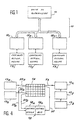
- la figure 1 est un schéma fonctionnel d'un système de pré-automatisation des installations d'un bâtiment industriel, tertiaire ou autre, selon l'invention;
- les figures 2 et 3 sont des schémas fonctionnels d'un appareil d'interconnexion selon la présente invention;
- la fiqure 4 est une vue schématique de câblages en étoile et en bus d'un appareil d'interconnexion, et
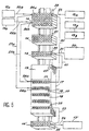
- la figure 5 est une vue d'un appareil d'interconnexion selon l'invention tel qu'il est monté sur un support de pré-câblage.
- Figure 1 is a block diagram of a pre-automation system for the installations of an industrial, tertiary or other building, according to the invention;
- Figures 2 and 3 are block diagrams of an interconnection apparatus according to the present invention;
- Figure 4 is a schematic view of star and bus wiring of an interconnection device, and
- Figure 5 is a view of an interconnection apparatus according to the invention as it is mounted on a pre-wiring support.
Sur la figure 1, un système de pré-automatisation selon
l'invention pour les installations d'un bâtiment
industriel, tertiaire ou autre comprend un réseau de
câbles 10 qui est prévu pour connecter une unité de
supervision 11 à des appareils d'interconnexion
121, 122...12n au nombre de n qui sont réalisés selon la
présente invention. Chaque appareil d'interconnexion
121 à 12n est connecté respectivement à
des capteurs et des actionneurs référencés 131 à 13n.
Chaque appareil d'interconnexion 12 comprend au
moins (figures 2 et 3) un bornier 14, 14' dont les
bornes sont connectées d'une part comme indiqué
ci-dessus, par des conducteurs 15, 15' à des capteurs 13
et des actionneurs 13' et, d'autre part, par des
conducteurs 16, 16' à un automate 17. L'automate 17
comprend un circuit d'entrées/sorties 18 qui est
connecté, d'une part, aux bornes 14, 14' et, d'autre
part, à une unité microprogrammée 19 tel qu'un
microprocesseur. In FIG. 1, a pre-automation system according to the invention for the installations of an industrial, tertiary or other building comprises a network of
Le circuit d'entrées/sorties 18 est également connecté à
l'unité de supervision 11 (figure 1) par le réseau de
câbles 10. Par ailleurs, le microprocesseur 19 peut être
connecté à un ordinateur portable 20 par un câble 21.The input /
Le circuit d'entrées/sorties 18 est prévu pour être
connecté, par l'intermédiaire du bornier 14, à des
capteurs 13a, 13b (figure 4) par des conducteurs
22a, 27a et 22b, 27b en étoile et à des capteurs
13x, 13y et 13z en série par un bus 23, 30.The input /
Le microprocesseur 19 est microprogrammé pour réaliser un certain nombre de fonctions telles que :
- l'acquisition d'informations en provenance des
capteurs 13, - la mémorisation des informations en provenance des
capteurs 13 avec leur date et leur heure d'acquisition, - la gestion des communications avec l'unité de
supervision 11, - le contrôle d'accès, la gestion des horaires et la
régulation, en local, sans l'intervention de l'unité
de
supervision 11, et - toutes autres fonctions qui peuvent être nécessaires pour une Gestion Technique du Bâtiment ou une Gestion Administrative Centralisée.
- the acquisition of information from the
sensors 13, - memorizing information from
sensors 13 with their date and time of acquisition, - managing communications with the
supervisory unit 11, - access control, schedule management and regulation, locally, without the intervention of the
supervision unit 11, and - all other functions that may be necessary for a Technical Building Management or Centralized Administrative Management.
La microprogrammation du microprocesseur 19 peut être
réalisée soit à partir de l'unité de supervision 11,
soit à partir de l'ordinateur portable 20.The microprocessor of the
Le microprocesseur 19 comprend de manière connue une
unité centrale, une mémoire vive et une mémoire morte
qui contient le programme de traitement des fonctions
définies ci-dessus.The
Les différents éléments d'un appareil
d'interconnexion selon l'invention sont montés sur une
ferme de pré-câblage 25 dans laquelle sont disposés les
câbles du réseau de pré-câblage comme le montre la
figure 5.The different elements of a device
interconnection according to the invention are mounted on a
Les capteurs 13a et 13b sont connectés respectivement
par des câbles 22a, 22b à des bornes 24a, 24b du
bornier 14 par sa face arrière. Ces bornes 24a, 24b
sont connectées, par la face avant du bornier,
respectivement par des câbles 27a, 27b à deux entrées
28a, 28b du circuit d'entrées/sorties 18.The
Les capteurs 13x, 13y et 13z sont connectés par un
bus 23 à une borne 28, par sa face arrière du bornier;
cette dernière est connectée par la face avant du
bornier à une borne d'entrée 31 du circuit
d'entrées/sorties 18 par un câble 30.The
De manière similaire, un actionneur 13' reçoit un signal
électrique par l'intermédiaire d'une borne de sortie 32
du circuit d'entrées/sorties 18, d'un premier, câble 33
qui le connecte à une borne 35 du bornier 14' par sa
face avant, et d'un deuxième câble 36 entre la face
arrière de la borne 35 et l'actionneur 13'.Similarly, an actuator 13 'receives a signal
electric via an
Les câbles 22a, 22b, 23 et 36 font partie du réseau de
pré-câblage et sont connectés au bornier 14, 14' par la
face arrière tandis que les câbles 27a, 27b, 30 et 33
sont mis en place à la demande et sont connectés au
bornier par la face avant.
Les bornes d'entrées/sorties du circuit d'entrées/sorties
18 peuvent être de tout type connu et présenter
chacune un repérage codé 37 et un voyant de
signalisation 38.The input / output terminals of the input /
L'ordinateur portable 20 est connect au microprocesseur
19 par l'intermédiaire du câble 21, une borne d'entrée
39 du bornier 14, d'une borne de sortie 40 et d'un
câble 41 connecté à une prise spéciale 42 du
microprocesseur 19. Dans une variante le câble 21 peut
être connecté directement à la prise spéciale 42. The
A titre indicatif, chaque appareil d'interconnexion est prévu pour être connecté à vingt-cinq capteurs et/ou actionneurs et il est donc nécessaire d'installer une quarantaine de dispositifs pour un système à mille points de mesure.As an indication, each interconnection device is intended to be connected to twenty-five sensors and / or actuators and it is therefore necessary to install forty devices for a system a thousand measuring points.
Claims (3)
- System for monitoring sensors (13) and actuators (13') in a building, comprising:a monitoring system (11) for acquiring data centrally from said sensors (13) and for controlling said actuators (13'),various interconnecting apparatuses (121, 122,...12n) which are connected to the above-mentioned actuators (13') and sensors, comprising:a) various terminal blocks (14, 14') connected to the above-mentioned sensors (13) and actuators (13') by conductors of a first series of cables (15, 15');b) a microprocessor (19) having various input/output connections, of which a part is connected to the above-mentioned terminal blocks (14, 14') by conductors of a second series of cables (16, 16') to transmit signals for controlling said actuators (13') and for receiving signals from the above-mentioned sensors (13); and a pre-cabling system (10) being located in said building, connecting the above-mentioned monitoring system (11) to a remaining part of said input/output connections, in whichc) said signals can be transferred to and from interconnection apparatuses and from the above-mentioned monitoring system (11) and the first above-mentioned series of cables (15) corresponds to pre-cabled cables in said building andd) in which said part of the above-mentioned input/output connections comprises a star connection with certain above-mentioned sensors (13) and a bus connection with other above-mentioned sensors (13).
- The system according to claim 1, in which said microprocessor (19) comprises a socket for a connection to a portable computer which programmes said microprocessor.
- The system according to claim 2, in which said interconnection apparatuses are supported on said pre-cabling system (10).
Applications Claiming Priority (3)
| Application Number | Priority Date | Filing Date | Title |
|---|---|---|---|
| FR9404157 | 1994-04-08 | ||
| FR9404157A FR2718543B1 (en) | 1994-04-08 | 1994-04-08 | System and device for the pre-automation of building installations. |
| PCT/FR1995/000442 WO1995027929A1 (en) | 1994-04-08 | 1995-04-06 | Building facility pre-automation system and device |
Publications (2)
| Publication Number | Publication Date |
|---|---|
| EP0702807A1 EP0702807A1 (en) | 1996-03-27 |
| EP0702807B1 true EP0702807B1 (en) | 2002-08-28 |
Family
ID=9461888
Family Applications (1)
| Application Number | Title | Priority Date | Filing Date |
|---|---|---|---|
| EP95916719A Expired - Lifetime EP0702807B1 (en) | 1994-04-08 | 1995-04-06 | Building facility pre-automation system and device |
Country Status (8)
| Country | Link |
|---|---|
| US (1) | US6059439A (en) |
| EP (1) | EP0702807B1 (en) |
| JP (1) | JP3058448B2 (en) |
| AT (1) | ATE223077T1 (en) |
| CA (1) | CA2164611C (en) |
| DE (1) | DE69527902T2 (en) |
| FR (1) | FR2718543B1 (en) |
| WO (1) | WO1995027929A1 (en) |
Families Citing this family (9)
| Publication number | Priority date | Publication date | Assignee | Title |
|---|---|---|---|---|
| RU2133490C1 (en) * | 1998-09-21 | 1999-07-20 | Гинзбург Виталий Вениаминович | Structurized system for monitoring and controlling engineering equipment of buildings |
| DE19964156B4 (en) * | 1999-01-25 | 2004-07-15 | Weidmüller Interface Gmbh & Co. | Electric device |
| ATE287101T1 (en) * | 1999-11-01 | 2005-01-15 | Abb Research Ltd | INTEGRATION OF A FIELD CONTROL DEVICE INTO A PLANT CONTROL SYSTEM |
| US20040000503A1 (en) * | 2002-06-28 | 2004-01-01 | Shah Ketan N. | Recloseable storage bag with porous evacuation portal |
| US6812848B2 (en) | 2002-08-12 | 2004-11-02 | Flo-Guard Water Leak Mitigation Systems, Llc | Water leak mitigation system |
| US7030767B2 (en) * | 2002-08-12 | 2006-04-18 | Flo-Guard Water Leak Mitigation Systems, L.L.C. | Water leak mitigation system |
| US7413336B2 (en) | 2003-08-29 | 2008-08-19 | 3M Innovative Properties Company | Adhesive stacking for multiple optical films |
| US7777832B2 (en) * | 2005-11-18 | 2010-08-17 | 3M Innovative Properties Company | Multi-function enhancement film |
| US20100109577A1 (en) * | 2008-11-05 | 2010-05-06 | Loughrey James F | Cascading addressable mastering protocol-based lighting system |
Family Cites Families (14)
| Publication number | Priority date | Publication date | Assignee | Title |
|---|---|---|---|---|
| US4275455A (en) * | 1977-07-11 | 1981-06-23 | Automation Systems, Inc. | Output interface card suitable for use with a programmable logic controller |
| CH629059A5 (en) * | 1978-02-08 | 1982-03-31 | Landis & Gyr Ag | ELECTRICAL CONNECTING PLATE WITH CONNECTORS FOR CONNECTING WIRE. |
| US4567557A (en) * | 1983-02-23 | 1986-01-28 | Burns Martin J | Building intelligence system |
| FR2589259B1 (en) * | 1985-10-24 | 1988-08-26 | Frachet Jean Paul | DEVICE FOR MODULAR CONNECTION OF THE ORGANS OF AN INDUSTRIAL INSTALLATION TO A PROGRAMMABLE CONTROL UNIT |
| US5001358A (en) * | 1988-02-19 | 1991-03-19 | Omron Tateisi Electronics Co. | Interface device |
| EP0345493B1 (en) * | 1988-06-08 | 1994-03-09 | Landis & Gyr Technology Innovation AG | Arrangement for the surveillance, control and regulation of a technical installation of a building automation system |
| JPH0278341A (en) * | 1988-09-14 | 1990-03-19 | Secom Co Ltd | Hierarchical bus star type composite communication system |
| US5086385A (en) * | 1989-01-31 | 1992-02-04 | Custom Command Systems | Expandable home automation system |
| SE466931B (en) * | 1990-08-29 | 1992-04-27 | Asea Brown Boveri | PROCESS ALIGNMENT SYSTEM |
| DE4223193A1 (en) * | 1992-07-15 | 1994-01-20 | Abb Patent Gmbh | Programmable controller with facility for plug in of test unit - allows inputs to be simulated or detection of analogue and digital signals for system testing |
| US5621662A (en) * | 1994-02-15 | 1997-04-15 | Intellinet, Inc. | Home automation system |
| US5528215A (en) * | 1994-05-31 | 1996-06-18 | Landis & Gyr Powers, Inc. | Building automation system having expansion modules |
| US5510975A (en) * | 1994-07-01 | 1996-04-23 | Atlantic Software, Inc. | Method of logical operations in home automation |
| DE4438804C1 (en) * | 1994-10-31 | 1996-03-28 | Weidmueller Interface | Modular control system with bus conductor e.g. B. for building automation |
-
1994
- 1994-04-08 FR FR9404157A patent/FR2718543B1/en not_active Expired - Fee Related
-
1995
- 1995-04-06 WO PCT/FR1995/000442 patent/WO1995027929A1/en active IP Right Grant
- 1995-04-06 AT AT95916719T patent/ATE223077T1/en not_active IP Right Cessation
- 1995-04-06 US US08/557,043 patent/US6059439A/en not_active Expired - Fee Related
- 1995-04-06 JP JP7526121A patent/JP3058448B2/en not_active Expired - Fee Related
- 1995-04-06 CA CA002164611A patent/CA2164611C/en not_active Expired - Fee Related
- 1995-04-06 DE DE69527902T patent/DE69527902T2/en not_active Expired - Fee Related
- 1995-04-06 EP EP95916719A patent/EP0702807B1/en not_active Expired - Lifetime
Also Published As
| Publication number | Publication date |
|---|---|
| FR2718543B1 (en) | 1996-06-21 |
| DE69527902D1 (en) | 2002-10-02 |
| EP0702807A1 (en) | 1996-03-27 |
| JP3058448B2 (en) | 2000-07-04 |
| FR2718543A1 (en) | 1995-10-13 |
| US6059439A (en) | 2000-05-09 |
| JPH09504400A (en) | 1997-04-28 |
| WO1995027929A1 (en) | 1995-10-19 |
| ATE223077T1 (en) | 2002-09-15 |
| DE69527902T2 (en) | 2003-01-02 |
| CA2164611C (en) | 2000-10-31 |
Similar Documents
| Publication | Publication Date | Title |
|---|---|---|
| US4771865A (en) | System for the remote management of elevator installations | |
| EP0702807B1 (en) | Building facility pre-automation system and device | |
| CN101490632B (en) | Building automation system | |
| EP1117018B1 (en) | Structured system for monitoring and controlling the engineering equipment of an installation | |
| FR2922664A1 (en) | AUTOMATIC GENERATION METHOD OF AN SSD FILE. | |
| GB2396920A (en) | Real-time viewing of turbine monitoring system data | |
| FR2904486A1 (en) | Targeted electrical equipment`s electrical power consumption controlling and modulating method, involves sending power supply cut order to box based on preset value, if value indicates to reduce power, and receiving and executing order | |
| MY115926A (en) | Troubleshooting computer systems during manufacturing using state and attiribute information | |
| CN104050807A (en) | On-line parking lot management system | |
| WO2020027538A1 (en) | Device and method for determining whether power generation system is abnormal | |
| US20160299515A1 (en) | Unitary telematic system for space management, with a universal general purpose | |
| CN114755223A (en) | Electronic equipment wiring monitoring method, device and system | |
| Atanassov | Advanced software architecture of an automatic vehicle number plate recognition system | |
| NL1004934C2 (en) | System for the central level and remote, using a computer or local by means of signal mediums, individual switching of electricity consumers in a building, where all control, supply and switching equipment is placed in one or more (daily) accessible central locations. All this by using the developed standardized Differentiated Electric Power Switch (öDEPSö) modules with associated system design. | |
| EP0410873B1 (en) | Device for interconnecting and extending busses in an information transmission network | |
| CN103926906A (en) | Industrial field bus system | |
| FR2695279A1 (en) | Device for automatic distribution of telephone and IT connections. | |
| CN113160468A (en) | Unmanned on duty system of oil gas station | |
| FR3074344A1 (en) | SYSTEM AND METHOD FOR BUILDING SUPERVISION | |
| EP3672107B1 (en) | Electrical distribution system provided with removable modules communicating by wireless optical beams | |
| KR102508560B1 (en) | DEVICE FOR MONITORING Control POWER AND ENVIRONMENTS, AND THE METHOD FOE INSTALLING OF THE DEVICE | |
| FR2744868A1 (en) | COMPUTER BREWING SYSTEM | |
| CN116566968A (en) | Distributed network data remote grabbing system based on cloud technology | |
| Wiecha et al. | Fully integrated control system for the Discovery Channel Telescope | |
| CA3225216A1 (en) | Cabling apparatuses and systems with low voltage digital connectivity |
Legal Events
| Date | Code | Title | Description |
|---|---|---|---|
| PUAI | Public reference made under article 153(3) epc to a published international application that has entered the european phase |
Free format text: ORIGINAL CODE: 0009012 |
|
| AK | Designated contracting states |
Kind code of ref document: A1 Designated state(s): AT BE CH DE DK ES FR GB IE IT LI LU MC NL SE |
|
| 17P | Request for examination filed |
Effective date: 19960328 |
|
| 17Q | First examination report despatched |
Effective date: 19990616 |
|
| GRAG | Despatch of communication of intention to grant |
Free format text: ORIGINAL CODE: EPIDOS AGRA |
|
| GRAG | Despatch of communication of intention to grant |
Free format text: ORIGINAL CODE: EPIDOS AGRA |
|
| GRAH | Despatch of communication of intention to grant a patent |
Free format text: ORIGINAL CODE: EPIDOS IGRA |
|
| GRAH | Despatch of communication of intention to grant a patent |
Free format text: ORIGINAL CODE: EPIDOS IGRA |
|
| GRAA | (expected) grant |
Free format text: ORIGINAL CODE: 0009210 |
|
| AK | Designated contracting states |
Kind code of ref document: B1 Designated state(s): AT BE CH DE DK ES FR GB IE IT LI LU MC NL SE |
|
| PG25 | Lapsed in a contracting state [announced via postgrant information from national office to epo] |
Ref country code: NL Free format text: LAPSE BECAUSE OF FAILURE TO SUBMIT A TRANSLATION OF THE DESCRIPTION OR TO PAY THE FEE WITHIN THE PRESCRIBED TIME-LIMIT Effective date: 20020828 Ref country code: IT Free format text: LAPSE BECAUSE OF FAILURE TO SUBMIT A TRANSLATION OF THE DESCRIPTION OR TO PAY THE FEE WITHIN THE PRESCRIBED TIME-LIMIT;WARNING: LAPSES OF ITALIAN PATENTS WITH EFFECTIVE DATE BEFORE 2007 MAY HAVE OCCURRED AT ANY TIME BEFORE 2007. THE CORRECT EFFECTIVE DATE MAY BE DIFFERENT FROM THE ONE RECORDED. Effective date: 20020828 Ref country code: IE Free format text: LAPSE BECAUSE OF FAILURE TO SUBMIT A TRANSLATION OF THE DESCRIPTION OR TO PAY THE FEE WITHIN THE PRESCRIBED TIME-LIMIT Effective date: 20020828 Ref country code: AT Free format text: LAPSE BECAUSE OF FAILURE TO SUBMIT A TRANSLATION OF THE DESCRIPTION OR TO PAY THE FEE WITHIN THE PRESCRIBED TIME-LIMIT Effective date: 20020828 |
|
| REF | Corresponds to: |
Ref document number: 223077 Country of ref document: AT Date of ref document: 20020915 Kind code of ref document: T |
|
| REG | Reference to a national code |
Ref country code: GB Ref legal event code: FG4D Free format text: NOT ENGLISH |
|
| REG | Reference to a national code |
Ref country code: CH Ref legal event code: EP |
|
| REF | Corresponds to: |
Ref document number: 69527902 Country of ref document: DE Date of ref document: 20021002 |
|
| REG | Reference to a national code |
Ref country code: IE Ref legal event code: FG4D Free format text: FRENCH |
|
| GBT | Gb: translation of ep patent filed (gb section 77(6)(a)/1977) |
Effective date: 20020919 |
|
| PG25 | Lapsed in a contracting state [announced via postgrant information from national office to epo] |
Ref country code: DK Free format text: LAPSE BECAUSE OF FAILURE TO SUBMIT A TRANSLATION OF THE DESCRIPTION OR TO PAY THE FEE WITHIN THE PRESCRIBED TIME-LIMIT Effective date: 20021128 |
|
| NLV1 | Nl: lapsed or annulled due to failure to fulfill the requirements of art. 29p and 29m of the patents act | ||
| PG25 | Lapsed in a contracting state [announced via postgrant information from national office to epo] |
Ref country code: ES Free format text: LAPSE BECAUSE OF FAILURE TO SUBMIT A TRANSLATION OF THE DESCRIPTION OR TO PAY THE FEE WITHIN THE PRESCRIBED TIME-LIMIT Effective date: 20030228 |
|
| PGFP | Annual fee paid to national office [announced via postgrant information from national office to epo] |
Ref country code: GB Payment date: 20030402 Year of fee payment: 9 |
|
| PG25 | Lapsed in a contracting state [announced via postgrant information from national office to epo] |
Ref country code: LU Free format text: LAPSE BECAUSE OF NON-PAYMENT OF DUE FEES Effective date: 20030406 |
|
| PGFP | Annual fee paid to national office [announced via postgrant information from national office to epo] |
Ref country code: FR Payment date: 20030418 Year of fee payment: 9 |
|
| PGFP | Annual fee paid to national office [announced via postgrant information from national office to epo] |
Ref country code: SE Payment date: 20030422 Year of fee payment: 9 |
|
| PG25 | Lapsed in a contracting state [announced via postgrant information from national office to epo] |
Ref country code: MC Free format text: LAPSE BECAUSE OF NON-PAYMENT OF DUE FEES Effective date: 20030430 Ref country code: LI Free format text: LAPSE BECAUSE OF NON-PAYMENT OF DUE FEES Effective date: 20030430 Ref country code: CH Free format text: LAPSE BECAUSE OF NON-PAYMENT OF DUE FEES Effective date: 20030430 Ref country code: BE Free format text: LAPSE BECAUSE OF NON-PAYMENT OF DUE FEES Effective date: 20030430 |
|
| PGFP | Annual fee paid to national office [announced via postgrant information from national office to epo] |
Ref country code: DE Payment date: 20030430 Year of fee payment: 9 |
|
| REG | Reference to a national code |
Ref country code: IE Ref legal event code: FD4D Ref document number: 0702807E Country of ref document: IE |
|
| PLBE | No opposition filed within time limit |
Free format text: ORIGINAL CODE: 0009261 |
|
| STAA | Information on the status of an ep patent application or granted ep patent |
Free format text: STATUS: NO OPPOSITION FILED WITHIN TIME LIMIT |
|
| 26N | No opposition filed |
Effective date: 20030530 |
|
| BERE | Be: lapsed |
Owner name: *ROBOT CONSULT Effective date: 20030430 |
|
| REG | Reference to a national code |
Ref country code: CH Ref legal event code: PL |
|
| PG25 | Lapsed in a contracting state [announced via postgrant information from national office to epo] |
Ref country code: GB Free format text: LAPSE BECAUSE OF NON-PAYMENT OF DUE FEES Effective date: 20040406 |
|
| PG25 | Lapsed in a contracting state [announced via postgrant information from national office to epo] |
Ref country code: SE Free format text: LAPSE BECAUSE OF NON-PAYMENT OF DUE FEES Effective date: 20040407 |
|
| PG25 | Lapsed in a contracting state [announced via postgrant information from national office to epo] |
Ref country code: DE Free format text: LAPSE BECAUSE OF NON-PAYMENT OF DUE FEES Effective date: 20041103 |
|
| GBPC | Gb: european patent ceased through non-payment of renewal fee | ||
| EUG | Se: european patent has lapsed | ||
| PG25 | Lapsed in a contracting state [announced via postgrant information from national office to epo] |
Ref country code: FR Free format text: LAPSE BECAUSE OF NON-PAYMENT OF DUE FEES Effective date: 20041231 |
|
| REG | Reference to a national code |
Ref country code: FR Ref legal event code: ST |