EP0702481A1 - Loss of carrier detector in a facsimile modem - Google Patents
Loss of carrier detector in a facsimile modem Download PDFInfo
- Publication number
- EP0702481A1 EP0702481A1 EP95410099A EP95410099A EP0702481A1 EP 0702481 A1 EP0702481 A1 EP 0702481A1 EP 95410099 A EP95410099 A EP 95410099A EP 95410099 A EP95410099 A EP 95410099A EP 0702481 A1 EP0702481 A1 EP 0702481A1
- Authority
- EP
- European Patent Office
- Prior art keywords
- amplitude
- output
- computer
- comparator
- loss detector
- Prior art date
- Legal status (The legal status is an assumption and is not a legal conclusion. Google has not performed a legal analysis and makes no representation as to the accuracy of the status listed.)
- Granted
Links
Images
Classifications
-
- H—ELECTRICITY
- H04—ELECTRIC COMMUNICATION TECHNIQUE
- H04L—TRANSMISSION OF DIGITAL INFORMATION, e.g. TELEGRAPHIC COMMUNICATION
- H04L1/00—Arrangements for detecting or preventing errors in the information received
- H04L1/20—Arrangements for detecting or preventing errors in the information received using signal quality detector
-
- H—ELECTRICITY
- H04—ELECTRIC COMMUNICATION TECHNIQUE
- H04N—PICTORIAL COMMUNICATION, e.g. TELEVISION
- H04N1/00—Scanning, transmission or reproduction of documents or the like, e.g. facsimile transmission; Details thereof
- H04N1/32—Circuits or arrangements for control or supervision between transmitter and receiver or between image input and image output device, e.g. between a still-image camera and its memory or between a still-image camera and a printer device
- H04N1/327—Initiating, continuing or ending a single-mode communication; Handshaking therefor
Definitions
- the value of the multiplying coefficient is chosen so that the value of the memorized threshold is attenuated, relative to the output of the first computer, by a value corresponding at least to the maximum amplitude of ripples that can present the output of the first computer
- the detector is associated with a device for identifying the sequence of determined signals which delivers a control signal to said switch, said sequence having a frequency spectrum of two determined frequencies.
- said identification device comprises a bandpass filter, associated with a second amplitude calculator, an output of which is sent, via a second multiplier, to a first input a second comparator, and a low-pass filter, associated with a third amplitude calculator, an output of which is sent, via a third multiplier, to a second input of the second comparator.
- the coefficient of the multiplier associated with the second computer is greater than the coefficient of the multiplier associated with the third computer.
- the carrier loss detector according to the invention differs from the conventional detector shown in FIG. 1 by the presence of a switch 6 responsible for periodically causing the recording, in the register 5, of the level present at the output of the amplitude calculator 1, assigned a coefficient K0 by means of a multiplier 7.
- the output of comparator 13 provides a two-state ENABLE signal indicating the presence or absence of segment three in the received signal Rx.
- the coefficient K1 of the multiplier 14 is approximately twice the coefficient K2 of the multiplier 15.
- the bandpass filter 9 is a narrow filter centered on the frequency of 1000 Hz and the lowpass filter 10 has a frequency 1760 Hz cutoff.
- the recognition device comprises a notch filter 16 on which is sent the signal received Rx by the modem after scanning.
- the output of this notch filter 16 is sent to a first amplitude calculator 11 whose output is connected to a first input of a comparator 13.
- the received signal Rx is also sent, directly, to a second computer amplitude 12, the output of which is connected to a second input of the comparator 13.
- a multiplier, respectively 14 and 15 is interposed between the output of each computer 11 and 12 and the input of the comparator with which it is associated.
- These multipliers 14 and 15 affect each computer output 11 or 12 by a positive coefficient and less than unity, K1 and K2 respectively, K1 being greater than K2.
Abstract
Description
La présente invention concerne le domaine des modulateurs/démodulateurs (modems) numériques et plus particulièrement l'opération de détection de perte de porteuse dans un modem utilisé pour la transmission de télécopies.The present invention relates to the field of digital modulators / demodulators (modems) and more particularly the operation of carrier loss detection in a modem used for the transmission of faxes.
Dans un modem utilisant un processeur de signal, les données à transmettre sont codées sous forme numérique à partir d'un certain nombre de symboles possibles puis transmises sous forme d'échantillons de portions d'une porteuse modulée, par exemple, en phase et en amplitude, puis convertis en signal analogique.In a modem using a signal processor, the data to be transmitted is coded in digital form from a certain number of possible symbols and then transmitted in the form of samples of portions of a modulated carrier, for example, in phase and in amplitude, then converted to analog signal.
Dans le cas des télécopieurs, les modems fonctionnent en mode bidirectionnel à l'alternat (semi-duplex) et sont susceptibles d'émettre et de recevoir des signaux correspondant à deux types de modulation. Une modulation en phase et en amplitude (QAM) ou une modulation différentielle de phase (DPH) d'une porteuse est utilisée pour la transmission des données. Une modulation par saut de fréquence (couramment appelée modulation FSK d'après l'expression anglo-saxonne Frequency Shift Keying) est utilisée pour échanger des informations sur la communication, en particulier, pour accuser réception de chaque page du document transmis par télécopie. La commutation d'une modulation QAM ou DPH vers une modulation FSK doit donc se produire à chaque fin de page du document transmis par télécopie. La détection d'une fin de page passe par la détection de la perte de la porteuse de la modulation QAM ou DPH.In the case of fax machines, the modems operate in two-way half-duplex mode and are capable of transmitting and receiving signals corresponding to two types of modulation. Phase and amplitude modulation (QAM) or differential phase modulation (DPH) of a carrier is used for data transmission. Frequency hopping modulation (commonly called FSK modulation from the English expression Frequency Shift Keying) is used to exchange information on the communication, in particular, to acknowledge receipt of each page of the document transmitted by fax. Switching from QAM or DPH modulation to FSK modulation must therefore occur at the end of each page of the document sent by fax. The detection of an end of page requires the detection of the loss of the carrier of the QAM or DPH modulation.
On utilise, côté récepteur, le niveau du signal reçu pour détecter la perte de porteuse. Un détecteur indique par une sortie à deux états, respectivement ON et OFF, la perte de la porteuse qui se caractérise par une atténuation du niveau du signal reçu.On the receiver side, the level of the received signal is used to detect the loss of carrier. A detector indicates by an output with two states, ON and OFF respectively, the loss of the carrier which is characterized by an attenuation of the level of the received signal.
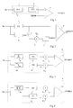
La figure 1 représente un exemple de détecteur de perte de porteuse classique. Ce détecteur comporte un calculateur 1 du niveau du signal reçu comprenant un circuit 2 de détermination de valeur absolue (fournissant la valeur absolue de l'amplitude du signal reçu Rx) dont la sortie est envoyée sur un moyenneur 3 constitué d'un filtre passe-bas récursif du premier ordre à fréquence de coupure nulle. Le signal Rx reçu par le calculateur 1 correspond au signal reçu par le modem après numérisation. Le moyenneur 3 sert à lisser les ondulations à la sortie du circuit 2 ainsi qu'à éviter une commutation intempestive du détecteur. Un comparateur 4 du détecteur reçoit, sur une entrée positive, la sortie du moyenneur 3 qui constitue la sortie du calculateur 1. Une entrée négative du comparateur 4 reçoit une valeur seuil prédéterminée THRSH à laquelle le niveau du signal reçu doit être comparée. La sortie du comparateur 4 délivre un signal de détection DETECT à deux états (ON ou OFF) indiquant la présence ou l'absence d'une porteuse.FIG. 1 shows an example of a conventional carrier loss detector. This detector comprises a
Un inconvénient de ce type de détecteur est que les caractéristiques de la ligne de transmission entre deux modems peuvent faire varier, de manière sensible, le niveau du signal reçu. Ces variations de niveau du signal reçu peuvent être comprises, par exemple, entre 0 dBm et -48 dBm. En utilisant, par exemple, pour le seuil THRSH, un niveau de -24 dBm, tout signal reçu d'un niveau inférieur à -24 dBm sera interprété comme une perte de porteuse. A l'inverse, si du bruit est mélangé au signal, le détecteur peut ne pas détecter la perte de porteuse.One drawback of this type of detector is that the characteristics of the transmission line between two modems can cause the level of the received signal to vary significantly. These variations in the level of the received signal can be included, for example, between 0 dBm and -48 dBm. By using, for example, for the THRSH threshold, a level of -24 dBm, any signal received of a level lower than -24 dBm will be interpreted as a carrier loss. Conversely, if noise is mixed with the signal, the detector may not detect the loss of carrier.
Le document JP-A-06 014062 décrit un autre exemple de détecteur de perte de porteuse utilisant un seuil mémorisé sur la base de l'énergie du signal reçu. Un tel détecteur est particulièrement complexe et nécessite des moyens additionnels pour commander la mémorisation du seuil d'énergie. De plus, il ne permet pas une adaptation d'un modem existant pourvu d'un détecteur tel que représenté à la figure 1 sans entraîner de modifications importantes du récepteur du modem. Un autre inconvénient d'un tel détecteur est qu'il est susceptible d'engendrer des erreurs de détection en raison du temps de réponse du filtre (passe-bande) utilisé.Document JP-A-06 014062 describes another example of a carrier loss detector using a threshold stored on the basis of the energy of the signal received. Such a detector is particularly complex and requires additional means to control the storage of the energy threshold. In addition, it does not allow an adaptation of an existing modem provided with a detector as shown in FIG. 1 without causing significant modifications to the receiver of the modem. Another drawback of such a detector is that it is liable to generate detection errors due to the response time of the filter (bandpass) used.
La présente invention vise à pallier ces inconvénients en proposant un détecteur de perte de porteuse qui soit à la fois rapide et fiable.The present invention aims to overcome these drawbacks by proposing a carrier loss detector which is both rapid and reliable.
L'invention vise également à proposer un tel détecteur qui puisse s'adapter à un détecteur de perte de porteuse et/ou à un modem existant sans entraîner de modifications importantes du récepteur du modem.The invention also aims to propose such a detector which can be adapted to a carrier loss detector and / or to an existing modem without causing significant modifications to the modem receiver.
Pour atteindre ces objets, la présente invention prévoit un détecteur de perte de porteuse dans un modem récepteur d'une transmission d'un document par télécopie, comportant :
un premier calculateur d'amplitude du signal reçu,
un premier comparateur de cette amplitude par rapport à un seuil, et
des moyens pour réaliser une adaptation dudit seuil entre chaque page du document transmis.To achieve these objects, the present invention provides a carrier loss detector in a modem receiving a transmission of a document by fax, comprising:
a first amplitude calculator of the received signal,
a first comparator of this amplitude with respect to a threshold, and
means for carrying out an adaptation of said threshold between each page of the transmitted document.
Selon un mode de réalisation de la présente invention, lesdits moyens comportent un registre de mémorisation d'un seuil qui correspond à un niveau d'amplitude du signal reçu pendant une séquence de signaux déterminés et un commutateur destiné à commander la mémorisation de l'amplitude du signal reçu issu du premier calculateur à l'apparition de la séquence de signaux déterminés, ladite séquence étant choisie pour présenter des signaux d'amplitude calibrée.According to an embodiment of the present invention, said means include a threshold storage register which corresponds to an amplitude level of the signal received during a sequence of determined signals and a switch intended to control the storage of the amplitude from the signal received from the first computer to the appearance of the sequence of determined signals, said sequence being chosen to present signals of calibrated amplitude.
Selon un mode de réalisation de la présente invention, le niveau d'amplitude devant être mémorisé est affecté d'un coefficient, inférieur à l'unité, au moyen d'un premier multiplieur intercalé entre une sortie du premier calculateur et une entrée de mémorisation du registre.According to an embodiment of the present invention, the amplitude level to be memorized is assigned a coefficient, less than unity, by means of a first multiplier interposed between an output of the first computer and a memorization input from the registry.
Selon un mode de réalisation de la présente invention, la valeur du coefficient multiplicateur est choisie pour que la valeur du seuil mémorisé soit atténuée, par rapport à la sortie du premier calculateur, d'une valeur correspondant au moins à l'amplitude maximale d'ondulations que peut présenter la sortie du premier calculateur.According to an embodiment of the present invention, the value of the multiplying coefficient is chosen so that the value of the memorized threshold is attenuated, relative to the output of the first computer, by a value corresponding at least to the maximum amplitude of ripples that can present the output of the first computer
Selon un mode de réalisation de la présente invention, le détecteur est associé à un dispositif d'identification de la séquence de signaux déterminés qui délivre un signal de commande audit commutateur, ladite séquence possédant un spectre fréquentiel de deux fréquences déterminées.According to an embodiment of the present invention, the detector is associated with a device for identifying the sequence of determined signals which delivers a control signal to said switch, said sequence having a frequency spectrum of two determined frequencies.
Selon un mode de réalisation de la présente invention, ledit dispositif d'identification comporte un filtre passe-bande, associé à un second calculateur d'amplitude dont une sortie est envoyée, par l'intermédiaire d'un second multiplieur, sur une première entrée d'un second comparateur, et un filtre passe-bas, associé à un troisième calculateur d'amplitude dont une sortie est envoyée, par l'intermédiaire d'un troisième multiplieur, sur une seconde entrée du second comparateur.According to an embodiment of the present invention, said identification device comprises a bandpass filter, associated with a second amplitude calculator, an output of which is sent, via a second multiplier, to a first input a second comparator, and a low-pass filter, associated with a third amplitude calculator, an output of which is sent, via a third multiplier, to a second input of the second comparator.
Selon un mode de réalisation de la présente invention, ledit dispositif d'identification comporte un filtre coupe-bandes, associé à un second calculateur d'amplitude dont une sortie est envoyée sur une première entrée d'un second comparateur, une seconde entrée du second comparateur recevant la sortie d'un troisième calculateur d'amplitude dont l'entrée reçoit, directement, ledit signal reçu.According to an embodiment of the present invention, said identification device comprises a notch filter, associated with a second amplitude calculator, an output of which is sent to a first input of a second comparator, a second input of the second comparator receiving the output of a third amplitude calculator whose input receives, directly, said received signal.
Selon un mode de réalisation de la présente invention, un multiplieur, par un coefficient prédéterminé, est intercalé entre la sortie de chaque calculateur du dispositif d'identification et l'entrée du second comparateur à laquelle ledit calculateur est associé.According to an embodiment of the present invention, a multiplier, by a predetermined coefficient, is interposed between the output of each computer of the identification device and the input of the second comparator with which said computer is associated.
Selon un mode de réalisation de la présente invention, le coefficient du multiplieur associé au second calculateur est supérieur au coefficient du multiplieur associé au troisième calculateur.According to an embodiment of the present invention, the coefficient of the multiplier associated with the second computer is greater than the coefficient of the multiplier associated with the third computer.
Selon un mode de réalisation de la présente invention, chaque calculateur d'amplitude comprend un circuit de détermination de la valeur absolue de l'amplitude du signal reçu et, constituant un moyenneur, un filtre numérique passe-bas récursif du premier ordre à fréquence de coupure nulle.According to an embodiment of the present invention, each amplitude calculator comprises a circuit for determining the absolute value of the amplitude of the received signal and, constituting an averager, a recursive low-pass digital filter of the first order at frequency of zero cut.
Ces objets, caractéristiques et avantages, ainsi que d'autres de la présente invention seront exposés en détail dans la description suivante de modes de réalisation particuliers faite à titre non limitatif en relation avec les figures jointes parmi lesquelles :
- la figure 1 décrite précédemment est destinée à exposer l'état de la technique et le problème posé ;
- la figure 2 représente un mode de réalisation d'un détecteur de perte de porteuse selon l'invention ;
- la figure 3 représente un mode de réalisation d'un circuit de commande d'un commutateur de mémorisation du seuil du détecteur de la figure 2 ; et
- la figure 4 représente une variante du mode de réalisation du circuit de commande représenté à la figure 3.
- Figure 1 described above is intended to expose the state of the art and the problem posed;
- FIG. 2 represents an embodiment of a carrier loss detector according to the invention;
- FIG. 3 represents an embodiment of a control circuit of a switch for memorizing the threshold of the detector of FIG. 2; and
- FIG. 4 represents a variant of the embodiment of the control circuit shown in FIG. 3.
Un détecteur de perte de porteuse selon l'invention, tel que représenté à la figure 2, comporte un comparateur 4 du niveau du signal reçu Rx, qui lui est fourni sur une entrée positive par un calculateur d'amplitude 1 constitué d'un circuit de détermination de la valeur absolue de l'amplitude du signal reçu et d'un moyenneur. Selon l'invention, on préfère utiliser un calculateur d'amplitude qui présente l'avantage d'une mise en oeuvre plus facile qu'un calculateur d'énergie élevant au carré le niveau du signal reçu. Le comparateur 4 reçoit, sur son entrée négative, une valeur seuil THRSH issue d'un registre 5.A carrier loss detector according to the invention, as shown in FIG. 2, includes a
Comme le montre la figure 2, le détecteur de perte de porteuse selon l'invention se distingue du détecteur classique représenté à la figure 1 par la présence d'un commutateur 6 chargé de provoquer périodiquement l'enregistrement, dans le registre 5, du niveau présent en sortie du calculateur d'amplitude 1, affecté d'un coefficient K0 au moyen d'un multiplieur 7.As shown in FIG. 2, the carrier loss detector according to the invention differs from the conventional detector shown in FIG. 1 by the presence of a switch 6 responsible for periodically causing the recording, in the
La position de repos du commutateur 6 est la position représentée à la figure 2.The rest position of the switch 6 is the position shown in FIG. 2.
Une caractéristique de la présente invention est que le seuil THRSH et le niveau courant du signal reçu sont, tous deux, obtenus au moyen d'un même calculateur d'amplitude 1. Ainsi, le fonctionnement d'un détecteur selon l'invention n'est pas altéré par des dérives éventuelles du fonctionnement du calculateur, dans la mesure où de telles dérives ne risquent pas de provoquer de divergences entre le calcul du seuil et du niveau courant. De plus, cela rend le fonctionnement du détecteur indépendant des tolérances de fabrication du calculateur. Ce qui n'est pas le cas de détecteurs (par exemple, un détecteur tel que décrit dans le document JP-A-06 014062) qui utilisent des calculateurs séparés pour obtenir le seuil et le niveau courant.A characteristic of the present invention is that the threshold THRSH and the current level of the received signal are both obtained by means of the
Un avantage de la présente invention est que le détecteur prend en compte le bruit, susceptible d'être mélangé au signal reçu, pour la détermination du seuil et du niveau courant d'amplitude.An advantage of the present invention is that the detector takes into account the noise, capable of being mixed with the received signal, for the determination of the threshold and the current amplitude level.
Périodiquement pendant la communication, le seuil THRSH est adapté en prenant, pour nouvelle valeur, l'amplitude du signal reçu Rx pendant une séquence déterminée qui est choisie pour correspondre à une émission d'une séquence de signaux calibrés en amplitude. Le choix d'une telle séquence est motivé par le fait que le niveau du signal reçu Rx pendant cette séquence, affecté du coefficient K0 inférieur à l'unité, peut alors représenter un seuil THRSH qui correspond à une absence de transmission de données.Periodically during the communication, the THRSH threshold is adapted by taking, for a new value, the amplitude of the signal received Rx during a determined sequence which is chosen to correspond to an emission of a sequence of signals calibrated in amplitude. The choice of such a sequence is motivated by the fact that the level of the signal received Rx during this sequence, affected by the coefficient K0 less than unity, can then represent a threshold THRSH which corresponds to an absence of data transmission.
Ceci constitue une caractéristique de la présente invention qui est de proposer un détecteur de perte de porteuse dont le seuil THRSH soit auto-adaptatif. On utilise pour cela le fait que, si des variations importantes peuvent se produire essentiellement entre deux communications en raison de lignes différentes, ces variations sont généralement faibles pendant une même communication.This is a feature of the present invention which is to provide a carrier loss detector whose THRSH threshold is self-adapting. It is used for this the fact that, if significant variations can occur essentially between two communications due to different lines, these variations are generally small during the same communication.
On peut donc prévoir d'adapter le seuil THRSH du détecteur de perte de porteuse entre chaque communication et, de préférence, entre chaque page transmise.Provision can therefore be made to adapt the THRSH threshold of the carrier loss detector between each communication and, preferably, between each page transmitted.
De façon particulièrement avantageuse, on utilise des signaux déterminés qui sont émis pendant une phase d'apprentissage, présente entre chaque transmission de page de document, pour effectuer cette adaptation du seuil THRSH.In a particularly advantageous manner, use is made of determined signals which are emitted during a learning phase, present between each transmission of a document page, to effect this adaptation of the THRSH threshold.
En effet, avant chaque transmission d'une page de document, une phase d'apprentissage est effectuée. Les recommandations CCITT prévoient une procédure d'apprentissage déterminée pour chaque norme de transmission en fixant le type de signaux devant être transmis et la durée maximale de la procédure d'apprentissage. Dans le cas de la norme V27, par exemple, qui correspond à une des normes utilisées pour la télécopie, une procédure d'apprentissage se divise en cinq segments.Indeed, before each transmission of a document page, a learning phase is carried out. The CCITT recommendations provide for a learning procedure determined for each transmission standard by fixing the type of signals to be transmitted and the maximum duration of the learning procedure. In the case of the V27 standard, for example, which corresponds to one of the standards used for facsimile, a learning procedure is divided into five segments.
Ces cinq segments correspondent à une émission particulière de signaux prédéterminés.These five segments correspond to a particular emission of predetermined signals.
Un premier segment consiste en une porteuse pure (dépourvue de modulation) émise à la fréquence de la porteuse de transmission de données, par exemple, 1800 Hz pour la norme V27.A first segment consists of a pure carrier (without modulation) transmitted at the frequency of the data transmission carrier, for example, 1800 Hz for the V27 standard.
Un deuxième segment consiste en une absence d'émission pendant une certaine durée.A second segment consists of an absence of transmission for a certain duration.
Un troisième segment consiste en un signal modulé par une fréquence donnée, en phase et en opposition de phase. Cette fréquence est, par exemple, de 1600 Hz pour la norme V27. Dans le domaine fréquentiel, cela correspond à émettre deux fréquences pures, l'une à 1000 Hz, l'autre à 2600 Hz.A third segment consists of a signal modulated by a given frequency, in phase and in phase opposition. This frequency is, for example, 1600 Hz for the V27 standard. In the frequency domain, this corresponds to transmitting two pure frequencies, one at 1000 Hz, the other at 2600 Hz.
Un quatrième segment consiste en un signal embrouillé aléatoire dans une plage de fréquence. Pour la norme V27, cette plage de fréquence est comprise entre 1000 et 2600 Hz.A fourth segment consists of a random scrambled signal in a frequency range. For the V27 standard, this frequency range is between 1000 and 2600 Hz.
Un cinquième segment consiste en un signal embrouillé encodé de manière prédéterminée.A fifth segment consists of a scrambled signal encoded in a predetermined manner.
L'invention propose d'utiliser le troisième segment pour réaliser l'adaptation du seuil de détection THRSH de perte de porteuse. Le choix de ce segment trois est motivé par le fait que les deux premiers segments ne sont pas toujours présents. En effet, ils ne sont présents que dans des phases d'apprentissage relatives à des modems pourvus de modules d'élimination d'écho. Quant aux quatrième et cinquième segments, ils comportent une modulation de la porteuse qui se rapproche d'une modulation par des symboles de données et se distinguent de ce fait difficilement des signaux reçus pendant la transmission d'une page de document.The invention proposes to use the third segment to adapt the THRSH detection threshold for carrier loss. The choice of this segment three is motivated by the fact that the first two segments are not always present. In fact, they are only present in learning phases relating to modems provided with echo cancellation modules. As for the fourth and fifth segments, they comprise a modulation of the carrier which is close to a modulation by data symbols and are therefore difficult to distinguish from the signals received during the transmission of a document page.
Par contre, le segment trois présente l'avantage d'être déjà détecté par le modem, notamment, pour ajuster une commande automatique de gain. Ainsi on dispose déjà dans le modem d'un signal ENABLE indicateur de la présence de ce segment, provenant d'un dispositif 8 d'identification du segment trois, qui peut alors servir de signal de commande du commutateur 6 d'adaptation de seuil.On the other hand, segment three has the advantage of already being detected by the modem, in particular, for adjusting an automatic gain control. Thus, there is already in the modem an ENABLE signal indicative of the presence of this segment, coming from a
Un avantage de la présente invention est qu'en utilisant, en guise de signal de commande, un signal déjà présent dans le modem, le détecteur d'un modem existant, par exemple tel que représenté à la figure 1, peut être modifié pour obtenir un détecteur selon l'invention. En effet, l'interrupteur 6, le multiplieur 7 et le registre 5 peuvent être insérés, entre la sortie du calculateur 1 et l'entrée négative du comparateur 4, sans autre modification du détecteur tel que représenté à la figure 1.An advantage of the present invention is that by using, as a control signal, a signal already present in the modem, the detector of an existing modem, for example as shown in FIG. 1, can be modified to obtain a detector according to the invention. In fact, the switch 6, the
On notera qu'une telle adaptation ne requiert pas de modification du calculateur 1 dans la mesure où le même calculateur est utilisé pour obtenir le seuil et la valeur courante.It will be noted that such an adaptation does not require modification of the
Le choix de la valeur du coefficient K0 du multiplieur 7 dépend de la norme de transmission. On choisira pour K0, une valeur telle qu'elle représente, pour la valeur du seuil THRSH obtenue en présence du segment trois, une atténuation du niveau du signal reçu Rx qui permette de considérer qu'elle correspond à la perte de la transmission. De plus, on veillera à ce que le niveau d'atténuation obtenu soit supérieur à l'amplitude maximale des ondulations que présente la sortie du moyenneur du calculateur 1 afin d'éviter des commutations intempestives.The choice of the value of the coefficient K0 of the
A titre d'exemple, on pourra choisir une atténuation de l'ordre de 6 dB pour la norme V27 ter, soit un coefficient K0 de l'ordre de 0,5. Pour la norme V27, le coefficient K0 pourra être de l'ordre de 0,25 représentant une atténuation de l'ordre de 12 dB. Pour la norme V17, le coefficient K0 pourra être de l'ordre de 0,125 représentant une atténuation de l'ordre de 18 dB.For example, we can choose an attenuation of the order of 6 dB for the V27 ter standard, ie a coefficient K0 of the order of 0.5. For standard V27, the coefficient K0 could be of the order of 0.25 representing an attenuation of the order of 12 dB. For standard V17, the coefficient K0 could be of the order of 0.125 representing an attenuation of the order of 18 dB.
La figure 3 représente un mode de réalisation classique d'un dispositif 8 d'identification de segment trois dont la sortie ENABLE est utilisée, selon l'invention, pour commander le commutateur 6. Ce circuit comporte un filtre passe-bande 9 et un filtre passe-bas 10 recevant, chacun, le signal Rx. Le signal Rx que reçoivent les filtres 9 et 10 correspond, comme dans le cas de la figure 2, au signal reçu par le modem après numérisation dans un convertisseur analogique/numérique (non représenté). Chaque filtre 9 ou 10 est suivi d'un calculateur d'amplitude, respectivement 11 et 12. Un comparateur 13 reçoit, sur une première entrée, la sortie d'un multiplieur 14 multipliant la sortie du calculateur 11 par un coefficient K1 et, sur une seconde entrée, la sortie d'un multiplieur 15 multipliant la sortie du calculateur 12 par un coefficient K2. La sortie du comparateur 13 fournit un signal ENABLE à deux états indiquant la présence ou l'absence du segment trois dans le signal reçu Rx. Le coefficient K1 du multiplieur 14 est approximativement le double du coefficient K2 du multiplieur 15. Pour la norme V27 ter, le filtre passe-bande 9 est un filtre étroit centré sur la fréquence de 1000 Hz et le filtre passe-bas 10 possède une fréquence de coupure de 1760 Hz.FIG. 3 represents a conventional embodiment of a
Ainsi, lorsque le segment trois est présent, c'est-à-dire deux fréquences pures de 1000 Hz et 2600 Hz, la première entrée du comparateur 13 est à un niveau supérieur à sa seconde entrée. En effet, le double du niveau de sortie du filtre passe-bande 9 est supérieur au niveau de sortie du filtre passe-bas 10.Thus, when segment three is present, that is to say two pure frequencies of 1000 Hz and 2600 Hz, the first input of
En présence d'un signal modulé (spectre plat entre 1000 Hz et 2600 Hz), ou de bruit sur la ligne, le niveau de sortie du filtre passe-bas 10 est supérieur au double du niveau de sortie du filtre passe-bande 9 en raison de l'étroitesse de ce dernier.In the presence of a modulated signal (flat spectrum between 1000 Hz and 2600 Hz), or of noise on the line, the output level of the low-
On préférera cependant, selon l'invention, avoir recours à un dispositif d'identification du segment trois qui soit fiable et rapide, même dans le cas d'une émission de segment trois de courte durée. En effet, la durée d'émission du segment trois sur la ligne de transmission dépend de la norme. Plus précisément, la durée de ce troisième segment dépend de l'option dans laquelle se trouvent les modems parmi deux options qui correspondent, respectivement, à un apprentissage initial (au début de la communication) ou à un apprentissage intermédiaire (entre chaque page). Pour la norme V27 ter, l'option d'apprentissage intermédiaire, dite option a, a une durée de 14 intervalles de symboles. L'option d'apprentissage initial, dite option b, a une durée de 50 intervalles de symboles. Les durées sont exprimées en nombres d'intervalles de symboles, ou bauds, car elles dépendent du débit en bits par seconde de la transmission, la norme V27 ter prévoyant deux vitesses de transmission (1200 bauds ou 2400 bits/s et 1600 bauds ou 4800 bits/s).However, it will be preferred, according to the invention, to use a device for identifying segment three which is reliable and rapid, even in the case of a transmission of segment three of short duration. Indeed, the transmission time of segment three on the transmission line depends on the standard. More precisely, the duration of this third segment depends on the option in which the modems are found among two options which correspond, respectively, to an initial learning (at the start of the communication) or to an intermediate learning (between each page). For the V27 ter standard, the intermediate learning option, called option a , has a duration of 14 symbol intervals. The initial learning option, called option b , has a duration of 50 symbol intervals. The durations are expressed in numbers of symbol intervals, or bauds, because they depend on the bit rate per bit of the transmission, the V27 ter standard providing for two transmission speeds (1200 baud or 2400 bits / s and 1600 baud or 4800 bits / s).
Si un détecteur classique de segment trois fonctionne correctement pour un segment trois de longue durée (par exemple, option b de la norme V27 ter qui correspond à 50 bauds, soit 31,25 ms), il ne permet pas de détecter de manière fiable le segment trois si celui-ci n'est émis que pendant une courte durée (par exemple, option a de la norme V27 ter qui correspond à 14 bauds, soit 8,75 ms). Cela est dû au temps de réponse du filtre passe-bande 1 dont la constante de temps est supérieure à 14 bauds en raison de son étroitesse.If a conventional segment three detector works properly for a long segment three (for example, option b of the V27 ter standard which corresponds to 50 baud, or 31.25 ms), it does not allow reliable detection of the segment three if this is only transmitted for a short time (for example, option a of the V27 ter standard which corresponds to 14 baud, or 8.75 ms). This is due to the response time of the
De fait, un filtre passe-bande numérique est classiquement un filtre récursif au moins du deuxième ordre constitué à partir d'intégrateurs, de multiplieurs et d'éléments de retard (registres à décalages). La structure et le comportement d'un filtre de ce type ont été décrits par P.-M. BEAUFILS et M. RAMI dans l'ouvrage "Le filtrage numérique", pages 216 à 224.In fact, a digital bandpass filter is conventionally a recursive filter at least of the second order made up of integrators, multipliers and delay elements (shift registers). The structure and behavior of a filter of this type have been described by P.-M. BEAUFILS and M. RAMI in the book "Digital filtering", pages 216 to 224.
Un inconvénient de ce type de filtre est que l'obtention d'un filtre passe-bande étroit, qui est nécessaire pour ne pas entraîner de fausses détections de segment trois, conduit à un filtre lent.A disadvantage of this type of filter is that obtaining a narrow bandpass filter, which is necessary in order not to cause false detections of segment three, leads to a slow filter.
Ainsi, selon une variante de l'invention, le dispositif d'identification du segment trois, dont le signal de sortie ENABLE commande le commutateur 6, est constitué selon la représentation de la figure 4.Thus, according to a variant of the invention, the device for identifying segment three, whose output signal ENABLE controls the switch 6, is constituted according to the representation of FIG. 4.
Comme le montre la figure 4, le dispositif de reconnaissance selon l'invention comporte un filtre coupe-bandes 16 sur lequel est envoyé le signal reçu Rx par le modem après numérisation. La sortie de ce filtre coupe-bandes 16 est envoyée sur un premier calculateur d'amplitude 11 dont la sortie est reliée à une première entrée d'un comparateur 13. Le signal reçu Rx est également envoyé, directement, sur un second calculateur d'amplitude 12 dont la sortie est reliée à une seconde entrée du comparateur 13. De préférence, un multiplieur, respectivement 14 et 15, est intercalé entre la sortie de chaque calculateur 11 et 12 et l'entrée du comparateur à laquelle il est associé. Ces multiplieurs 14 et 15 affectent chaque sortie de calculateur 11 ou 12 d'un coefficient positif et inférieur à l'unité, respectivement K1 et K2, K1 étant supérieur à K2.As shown in Figure 4, the recognition device according to the invention comprises a notch filter 16 on which is sent the signal received Rx by the modem after scanning. The output of this notch filter 16 is sent to a
Le filtre coupe-bandes 16 comporte deux fréquences de coupure qui correspondent aux deux fréquences présentes dans le segment trois, soit pour la norme V27 ter, 1000 Hz et 2600 Hz.The notch filter 16 has two cutoff frequencies which correspond to the two frequencies present in segment three, ie for the V27 ter standard, 1000 Hz and 2600 Hz.
Un avantage de l'emploi d'un tel filtre coupe-bandes 16 est qu'il est aisément réalisable sous la forme d'un filtre numérique non récursif possédant une faible constante de temps. Cela n'est pas le cas d'un filtre passe-bande dans la mesure où un filtre non récursif ne comporte que des zéros (fréquences pour lesquelles l'atténuation est infinie). Il faudrait donc multiplier le nombre d'éléments de retard du filtre pour entourer la fréquence centrale d'une multitude de zéros (fréquences coupées) dans la mesure où l'on cherche à obtenir une fréquence non coupée déterminée, ce qui conduirait à un temps de propagation très élevé du signal dans le filtre. Par contre, pour un filtre coupe-bandes, les fréquences déterminées sont précisément des fréquences coupées, donc des zéros.An advantage of using such a notch filter 16 is that it is easily achievable in the form of a non-recursive digital filter having a low time constant. This is not the case for a bandpass filter since a non-recursive filter only has zeros (frequencies for which the attenuation is infinite). It would therefore be necessary to multiply the number of delay elements of the filter to surround the central frequency of a multitude of zeros (cut frequencies) insofar as it is sought to obtain a determined uncut frequency, which would lead to a very high propagation time of the signal in the filter. On the other hand, for a notch filter, the determined frequencies are precisely cut frequencies, therefore zeros.
Au moyen d'un dispositif tel que représenté à la figure 4, la présence du segment trois entraîne un niveau élevé en sortie du calculateur 12 qui reçoit le signal Rx en direct, et un très faible niveau en sortie du calculateur 11 dans la mesure où les deux fréquences ont été coupées par le filtre 16. Le bruit susceptible d'être mélangé au signal reçu Rx est ici sans incidence dans la mesure où sa contribution est pratiquement la même sur les deux calculateurs 11 et 12 car les filtres coupe-bandes sont relativement étroits.By means of a device as shown in FIG. 4, the presence of segment three results in a high level at the output of the
En l'absence du segment trois, c'est-à-dire en présence d'un signal modulé, de bruit ou d'un segment trois d'une autre norme de transmission, les sorties des deux calculateurs 11 et 12 sont sensiblement aux mêmes niveaux.In the absence of segment three, that is to say in the presence of a modulated signal, of noise or of segment three of another transmission standard, the outputs of the two
Les calculateurs d'amplitude 11 et 12 (figure 3 ou 4) sont, comme le calculateur 1 (figure 2), constitués d'un circuit de détermination de la valeur absolue de l'amplitude du signal reçu et d'un filtre numérique passe-bas récursif du premier ordre à fréquence de coupure nulle constituant un moyenneur.The
Un avantage du circuit de détermination tel que représenté à la figure 4 est que, dans la conception d'un récepteur d'un modem, les calculateurs 1 (figure 2) et 11 (figure 4) peuvent être confondus. En effet, ils reçoivent le même signal (le signal reçu après numérisation) et délivrent la même information (une valeur moyenne de la valeur absolue de l'amplitude du signal reçu).An advantage of the determination circuit as shown in FIG. 4 is that, in the design of a receiver for a modem, the computers 1 (FIG. 2) and 11 (FIG. 4) can be combined. Indeed, they receive the same signal (the signal received after digitization) and deliver the same information (an average value of the absolute value of the amplitude of the received signal).
Les coefficients des multiplieurs 14 et 15 sont, de préférence, choisis pour que le niveau de sortie du calculateur 12 soit divisé par deux par rapport au niveau de sortie du calculateur 11. Cela permet de différencier aisément les deux cas possibles au niveau du comparateur 13, une des deux entrées du comparateur (la première en l'absence du segment trois, la seconde en présence du segment trois) ayant alors toujours un niveau supérieur à l'autre.The coefficients of the
Ainsi, à chaque apparition d'un segment trois, on adapte le seuil THRSH du comparateur 4 qui servira à détecter la fin de la page suivante du document transmis. On dispose donc d'un détecteur de perte de porteuse particulièrement fiable, même en cas de variations des caractéristiques de la ligne durant la transmission d'un document.Thus, at each appearance of a segment three, the threshold THRSH of the
On veillera cependant à choisir la constante de temps du moyenneur 3 pour qu'elle permette, à la fois, un calcul suffisamment rapide de l'amplitude du signal reçu pendant que le segment trois est présent et un respect de la contrainte relative à l'amplitude maximale des ondulations de la sortie du moyenneur, afin d'éviter de provoquer une fausse détection.However, care will be taken to choose the time constant of the
Bien entendu, la présente invention est susceptible de diverses variantes et modifications qui apparaîtront à l'homme de l'art. En particulier, chacun des composants décrits pourra être remplacé par un ou plusieurs éléments remplissant la même fonction.Of course, the present invention is susceptible of various variants and modifications which will appear to those skilled in the art. In particular, each of the components described may be replaced by one or more elements fulfilling the same function.
De plus, alors que certaines des explications précédentes ont été données par soucis de clarté en utilisant un vocabulaire qui correspond parfois à un fonctionnement analogique, il sera clair pour l'homme du métier que tous les éléments du circuit selon la présente invention traitent des signaux numériques et que les constituants du circuit illustrés sous forme matérielle pourront correspondre en pratique à des réalisations logicielles.In addition, while some of the previous explanations have been given for the sake of clarity by using a vocabulary which sometimes corresponds to analog operation, it will be clear to those skilled in the art that all the elements of the circuit according to the present invention process signals. digital and that the components of the circuit illustrated in hardware form may correspond in practice to software implementations.
Claims (10)
un premier calculateur d'amplitude (1) du signal reçu (Rx),
un premier comparateur (4) de cette amplitude par rapport à un seuil (THRSH), et
des moyens (5, 6, 7, 8) pour réaliser une adaptation dudit seuil (THRSH) entre chaque page du document transmis.Carrier loss detector in a modem receiving a document transmission by fax, comprising:
a first amplitude calculator (1) of the received signal (Rx),
a first comparator (4) of this amplitude with respect to a threshold (THRSH), and
means (5, 6, 7, 8) for adapting said threshold (THRSH) between each page of the transmitted document.
Applications Claiming Priority (2)
| Application Number | Priority Date | Filing Date | Title |
|---|---|---|---|
| FR9411212A FR2724517B1 (en) | 1994-09-14 | 1994-09-14 | CARRIER LOSS DETECTOR IN A FAX MODEM |
| FR9411212 | 1994-09-14 |
Publications (2)
| Publication Number | Publication Date |
|---|---|
| EP0702481A1 true EP0702481A1 (en) | 1996-03-20 |
| EP0702481B1 EP0702481B1 (en) | 1999-11-17 |
Family
ID=9467101
Family Applications (1)
| Application Number | Title | Priority Date | Filing Date |
|---|---|---|---|
| EP95410099A Expired - Lifetime EP0702481B1 (en) | 1994-09-14 | 1995-09-08 | Loss of carrier detector in a facsimile modem |
Country Status (4)
| Country | Link |
|---|---|
| US (1) | US5815534A (en) |
| EP (1) | EP0702481B1 (en) |
| DE (1) | DE69513355T2 (en) |
| FR (1) | FR2724517B1 (en) |
Families Citing this family (17)
| Publication number | Priority date | Publication date | Assignee | Title |
|---|---|---|---|---|
| US6553518B1 (en) | 1999-03-08 | 2003-04-22 | International Business Machines Corporation | Severe error detectors, methods and computer program products that use constellation specific error event thresholds to detect severe error events during demodulation of a signal comprising symbols from a plurality of symbol constellations |
| US6661847B1 (en) | 1999-05-20 | 2003-12-09 | International Business Machines Corporation | Systems methods and computer program products for generating and optimizing signal constellations |
| US6505222B1 (en) | 1999-10-29 | 2003-01-07 | International Business Machines Corporation | Systems methods and computer program products for controlling undesirable bias in an equalizer |
| US6611563B1 (en) | 1999-10-29 | 2003-08-26 | International Business Machines Corporation | Systems, methods and computer program products for data mode refinement of modem constellation points |
| US6754258B1 (en) | 1999-10-29 | 2004-06-22 | International Business Machines Corporation | Systems, methods and computer program products for averaging learned levels in the presence of digital impairments based on patterns |
| US6823017B1 (en) | 1999-10-29 | 2004-11-23 | International Business Machines Corporation | Systems, methods and computer program products for filtering glitches from measured values in a sequence of code points |
| US6765955B1 (en) | 1999-10-29 | 2004-07-20 | International Business Machines Corporation | Methods, systems and computer program products establishing a communication configuration for a modem connection to compensate for echo noise |
| US6650657B1 (en) | 1999-10-29 | 2003-11-18 | International Business Machines Corporation | Systems, methods and computer program products for identifying digital impairments in modem signals |
| US6662322B1 (en) | 1999-10-29 | 2003-12-09 | International Business Machines Corporation | Systems, methods, and computer program products for controlling the error rate in a communication device by adjusting the distance between signal constellation points |
| US6792004B1 (en) | 1999-10-29 | 2004-09-14 | International Business Machines Corporation | Systems, methods and computer program products for averaging learned levels in the presence of robbed-bit signaling based on proximity |
| US6816545B1 (en) | 1999-10-29 | 2004-11-09 | International Business Machines Corporation | Systems, methods and computer program products for identifying digital impairments in modems based on clusters and/or skips in pulse code modulation signal levels |
| US6792040B1 (en) | 1999-10-29 | 2004-09-14 | International Business Machines Corporation | Modems having a dual power mode capability and methods of operating same |
| US6826157B1 (en) | 1999-10-29 | 2004-11-30 | International Business Machines Corporation | Systems, methods, and computer program products for controlling data rate reductions in a communication device by using a plurality of filters to detect short-term bursts of errors and long-term sustainable errors |
| US6823004B1 (en) | 1999-10-29 | 2004-11-23 | International Business Machines Corporation | Methods, systems and computer program products for monitoring performance of a modem during a connection |
| US6452966B1 (en) * | 2000-01-19 | 2002-09-17 | Charles Industries, Ltd. | Digital signal carrier detector |
| US8131238B2 (en) * | 2008-03-20 | 2012-03-06 | Infineon Technologies Ag | Carrier signal detection |
| US10200163B1 (en) * | 2017-08-22 | 2019-02-05 | Texas Instruments Incorporated | Small and seamless carrier detector |
Citations (4)
| Publication number | Priority date | Publication date | Assignee | Title |
|---|---|---|---|---|
| JPS636935A (en) * | 1986-06-26 | 1988-01-12 | Toshiba Corp | Preamble detection circuit |
| WO1992021193A1 (en) * | 1991-05-10 | 1992-11-26 | Echelon Corporation | Adaptive carrier detection |
| JPH0614062A (en) | 1992-06-25 | 1994-01-21 | Mitsubishi Electric Corp | Carrier detector |
| GB2275395A (en) * | 1993-02-18 | 1994-08-24 | Fujitsu Ltd | Multiple frequency modem |
Family Cites Families (6)
| Publication number | Priority date | Publication date | Assignee | Title |
|---|---|---|---|---|
| US3990048A (en) * | 1973-11-23 | 1976-11-02 | Xerox Corporation | Carrier detect circuit |
| US4387401A (en) * | 1979-05-30 | 1983-06-07 | Rca Corporation | Carrier detector apparatus useful in a multiband sweep type tuning system |
| US4554508A (en) * | 1983-12-07 | 1985-11-19 | American Microsystems, Incorporated | Carrier detection circuit |
| US5181226A (en) * | 1989-03-06 | 1993-01-19 | Raytheon Company | Threshold level generator |
| US5596418A (en) * | 1990-08-17 | 1997-01-21 | Samsung Electronics Co., Ltd. | Deemphasis and subsequent reemphasis of high-energy reversed-spectrum components of a folded video signal |
| US5598441A (en) * | 1994-10-13 | 1997-01-28 | Westinghouse Electric Corp. | Carrier acquisition technique for mobile radio QPSK demodulator |
-
1994
- 1994-09-14 FR FR9411212A patent/FR2724517B1/en not_active Expired - Fee Related
-
1995
- 1995-09-08 EP EP95410099A patent/EP0702481B1/en not_active Expired - Lifetime
- 1995-09-08 DE DE69513355T patent/DE69513355T2/en not_active Expired - Fee Related
- 1995-09-12 US US08/527,055 patent/US5815534A/en not_active Expired - Lifetime
Patent Citations (4)
| Publication number | Priority date | Publication date | Assignee | Title |
|---|---|---|---|---|
| JPS636935A (en) * | 1986-06-26 | 1988-01-12 | Toshiba Corp | Preamble detection circuit |
| WO1992021193A1 (en) * | 1991-05-10 | 1992-11-26 | Echelon Corporation | Adaptive carrier detection |
| JPH0614062A (en) | 1992-06-25 | 1994-01-21 | Mitsubishi Electric Corp | Carrier detector |
| GB2275395A (en) * | 1993-02-18 | 1994-08-24 | Fujitsu Ltd | Multiple frequency modem |
Non-Patent Citations (2)
| Title |
|---|
| PATENT ABSTRACTS OF JAPAN vol. 012, no. 207 (E - 621) 14 June 1988 (1988-06-14) * |
| PATENT ABSTRACTS OF JAPAN vol. 018, no. 218 (E - 1539) 19 April 1994 (1994-04-19) * |
Also Published As
| Publication number | Publication date |
|---|---|
| US5815534A (en) | 1998-09-29 |
| FR2724517B1 (en) | 1996-12-13 |
| DE69513355D1 (en) | 1999-12-23 |
| EP0702481B1 (en) | 1999-11-17 |
| DE69513355T2 (en) | 2000-06-08 |
| FR2724517A1 (en) | 1996-03-15 |
Similar Documents
| Publication | Publication Date | Title |
|---|---|---|
| EP0702481B1 (en) | Loss of carrier detector in a facsimile modem | |
| EP0757452A1 (en) | Telecommunication system through electrical power lines | |
| EP0282393B1 (en) | Device for the realization of the hands free function in a telephone set associated with the functions of gain switching and echo cancelling | |
| EP0130263B1 (en) | Starting-up method for an echo canceller filter, and communication system using this method | |
| EP0421897B1 (en) | Device for extracting digital data from a video signal | |
| FR2602944A1 (en) | Subscriber unit for wireless digital telephone; modem and diverse devices (frequency synthesizer etc.) for this unit | |
| WO2004023682A1 (en) | Data transmission system and method using sound waves | |
| EP0329537A1 (en) | Transmission system using MSK modulation and coherent differential detection | |
| EP0013343A1 (en) | Process and device to detect a pseudo-random sequence of 0 degree and 180 degree phase changes of the carrier in a data receiver | |
| EP0125979B1 (en) | Demodulator for constant envelope and continuous phase signals angularly modulated by a series of binary symbols | |
| EP0702469B1 (en) | Detector for FSK training sequences | |
| FR2517906A1 (en) | ECHO CANCELLATOR WITH AUTOMATIC GAIN CONTROL FOR TRANSMISSION SYSTEMS | |
| FR2736231A1 (en) | DIGITAL COMMUNICATION SYSTEM COMPRISING A RECEIVER HAVING A RHYTHM RECOVERY DEVICE | |
| EP0756389A1 (en) | Assignment circuit for a transmission channel on the mains network | |
| EP0702468B1 (en) | Apparatus for the identification of a synchronisation sequence | |
| EP0080544A1 (en) | Method for receiving a data signal with double side-band quadrature carrier modulation | |
| FR2546693A1 (en) | ADAPTIVE DIGITAL FILTER ECHO CANCELLATOR FOR TRANSMISSION SYSTEM | |
| FR2717646A1 (en) | Digital broadband recovery device of a carrier. | |
| EP0755128A1 (en) | Transmission circuit for binary data on the mains network using several transmission channels | |
| EP0494003B1 (en) | Receiver for processing signals which are received over diversity paths | |
| EP0035434B1 (en) | Transmitting and receiving device for the transmission of digital signals | |
| EP0470548B1 (en) | Method for controlling attenuation in a digital hands-free telephone set | |
| FR2788184A1 (en) | METHOD, DEVICE FOR DETECTING THE CALLING OF A TELEPHONE AND MODEM COMPRISING SUCH A DEVICE | |
| FR2720575A1 (en) | Post-demodulation adaptor for TDMA signal | |
| FR2675001A1 (en) | Method and device for digital modulation with components in phase and in quadrature and transmission installation including an application thereof |
Legal Events
| Date | Code | Title | Description |
|---|---|---|---|
| PUAI | Public reference made under article 153(3) epc to a published international application that has entered the european phase |
Free format text: ORIGINAL CODE: 0009012 |
|
| AK | Designated contracting states |
Kind code of ref document: A1 Designated state(s): DE FR GB IT |
|
| 17P | Request for examination filed |
Effective date: 19960828 |
|
| GRAG | Despatch of communication of intention to grant |
Free format text: ORIGINAL CODE: EPIDOS AGRA |
|
| 17Q | First examination report despatched |
Effective date: 19981118 |
|
| RAP3 | Party data changed (applicant data changed or rights of an application transferred) |
Owner name: STMICROELECTRONICS S.A. |
|
| GRAG | Despatch of communication of intention to grant |
Free format text: ORIGINAL CODE: EPIDOS AGRA |
|
| GRAH | Despatch of communication of intention to grant a patent |
Free format text: ORIGINAL CODE: EPIDOS IGRA |
|
| GRAH | Despatch of communication of intention to grant a patent |
Free format text: ORIGINAL CODE: EPIDOS IGRA |
|
| GRAA | (expected) grant |
Free format text: ORIGINAL CODE: 0009210 |
|
| AK | Designated contracting states |
Kind code of ref document: B1 Designated state(s): DE FR GB IT |
|
| REF | Corresponds to: |
Ref document number: 69513355 Country of ref document: DE Date of ref document: 19991223 |
|
| GBT | Gb: translation of ep patent filed (gb section 77(6)(a)/1977) |
Effective date: 19991220 |
|
| ITF | It: translation for a ep patent filed |
Owner name: BOTTI & FERRARI S.R.L. |
|
| PLBE | No opposition filed within time limit |
Free format text: ORIGINAL CODE: 0009261 |
|
| STAA | Information on the status of an ep patent application or granted ep patent |
Free format text: STATUS: NO OPPOSITION FILED WITHIN TIME LIMIT |
|
| 26N | No opposition filed | ||
| REG | Reference to a national code |
Ref country code: GB Ref legal event code: IF02 |
|
| PGFP | Annual fee paid to national office [announced via postgrant information from national office to epo] |
Ref country code: DE Payment date: 20040902 Year of fee payment: 10 |
|
| PGFP | Annual fee paid to national office [announced via postgrant information from national office to epo] |
Ref country code: FR Payment date: 20050823 Year of fee payment: 11 |
|
| PGFP | Annual fee paid to national office [announced via postgrant information from national office to epo] |
Ref country code: GB Payment date: 20050907 Year of fee payment: 11 |
|
| PG25 | Lapsed in a contracting state [announced via postgrant information from national office to epo] |
Ref country code: IT Free format text: LAPSE BECAUSE OF NON-PAYMENT OF DUE FEES Effective date: 20050908 |
|
| PG25 | Lapsed in a contracting state [announced via postgrant information from national office to epo] |
Ref country code: DE Free format text: LAPSE BECAUSE OF NON-PAYMENT OF DUE FEES Effective date: 20060401 |
|
| GBPC | Gb: european patent ceased through non-payment of renewal fee |
Effective date: 20060908 |
|
| REG | Reference to a national code |
Ref country code: FR Ref legal event code: ST Effective date: 20070531 |
|
| PG25 | Lapsed in a contracting state [announced via postgrant information from national office to epo] |
Ref country code: GB Free format text: LAPSE BECAUSE OF NON-PAYMENT OF DUE FEES Effective date: 20060908 |
|
| PG25 | Lapsed in a contracting state [announced via postgrant information from national office to epo] |
Ref country code: FR Free format text: LAPSE BECAUSE OF NON-PAYMENT OF DUE FEES Effective date: 20061002 |