EP0695671A1 - Airbag system with serviceable tethered cover - Google Patents
Airbag system with serviceable tethered cover Download PDFInfo
- Publication number
- EP0695671A1 EP0695671A1 EP95305387A EP95305387A EP0695671A1 EP 0695671 A1 EP0695671 A1 EP 0695671A1 EP 95305387 A EP95305387 A EP 95305387A EP 95305387 A EP95305387 A EP 95305387A EP 0695671 A1 EP0695671 A1 EP 0695671A1
- Authority
- EP
- European Patent Office
- Prior art keywords
- cover
- airbag
- tether
- panel
- opening
- Prior art date
- Legal status (The legal status is an assumption and is not a legal conclusion. Google has not performed a legal analysis and makes no representation as to the accuracy of the status listed.)
- Granted
Links
Images


Classifications
-
- B—PERFORMING OPERATIONS; TRANSPORTING
- B60—VEHICLES IN GENERAL
- B60R—VEHICLES, VEHICLE FITTINGS, OR VEHICLE PARTS, NOT OTHERWISE PROVIDED FOR
- B60R21/00—Arrangements or fittings on vehicles for protecting or preventing injuries to occupants or pedestrians in case of accidents or other traffic risks
- B60R21/02—Occupant safety arrangements or fittings, e.g. crash pads
- B60R21/16—Inflatable occupant restraints or confinements designed to inflate upon impact or impending impact, e.g. air bags
- B60R21/20—Arrangements for storing inflatable members in their non-use or deflated condition; Arrangement or mounting of air bag modules or components
- B60R21/215—Arrangements for storing inflatable members in their non-use or deflated condition; Arrangement or mounting of air bag modules or components characterised by the covers for the inflatable member
- B60R21/216—Arrangements for storing inflatable members in their non-use or deflated condition; Arrangement or mounting of air bag modules or components characterised by the covers for the inflatable member comprising tether means for limitation of cover motion during deployment
Definitions
- the present invention relates to a serivceable, tethered cover, airbag system and more particularly to a motor vehicle airbag system employing a cover with a flexible tether detachably interconnected thereto to facilitate repair or replacement of the cover when desired.
- airbag cushioning devices used in motor vehicles, it is desirable to restrain and limit the amount of travel or movement of a cover or door away from a panel opening during airbag deployment.
- the cover or door normally closes an opening in a panel or a steering wheel. It is also desirable to prevent a cover or door from fracturing into pieces or fragments upon airbag deployment.
- an airbag cover commonly provides a portion of a panel or steering wheel surface in a passenger compartment of a vehicle, the cover can become defective, damaged or unsightly and it is desirable to replace or repair the cover without requiring disturbance of other components of the airbag system.
- U.S. Patent No. 3,822,894 to Muller et al. discloses a steering wheel having a built-in air cushion employing a strong hinge between a cover and a dish containing the airbag so that on inflation, the cover is pushed away but not completely liberated from attachment to the steering wheel.
- the Wulf et al. U.S. Patent No. 3,944,250, discloses an automatically inflatable gas cushion for the protection of passengers in vehicles employing a cover which is opened upon inflation of the airbag or gas cushion and which is retained by a flexible band so that the cover is restrained after opening.
- the Hirabayashi, U.S. Patent No. 4,911,471 discloses an arrangement of an airbag device in a motor vehicle wherein angular pivotal movement of a door over the airbag is restricted by a strap to limit the angular degree of opening when the airbag is inflated.
- U.S. Patent No. 4,964,653 to Parker discloses a self-skinned foam closure element for an inflatable restraint door assembly having a combination hinge and tether for restraining travel of the closure element during airbag deployment.
- U.S. Patent No. 5,064,217 to Shiracki discloses a cover for an airbag unit having "Nylon" yarn bands molded in place and wrapped around a retaining band of resin provided on the airbag enclosure or housing.
- U.S. Patent No. 5,150,919 to Sakakida et al. discloses an airbag system for a vehicle having a pair of doors or lids which pivotally open in opposite direction and which are restrained by belt members so that the lids pivot about transverse axes and open smoothly upon airbag deployment.
- U.S. Patent No. 5,195,776 to Sakakida et al. discloses an airbag installation having curved airbag cover lids which are reliably opened by rotation about a center point so as not to restrict the inflation of the airbag.
- U.S. Patent No. 5,072,967 to Batchelder et al. discloses an instrument panel having an invisible airbag deployment door with weakened sections formed therein but hidden from view for facilitating fracture of the door along predetermined lines for opening movement during airbag deployment.
- U.S. Patent No. 5,096,221 discloses an airbag door having plural substrates on the inside which normally retain the door in a closed position and at least one of which is notched or provided with a hidden tear seam to facilitate fracture for opening of the door.
- the Catron et al. U.S. Patent No. 5,211,421, discloses an airbag cover door retainer having bifurcated engagement flanges on the door normally retaining the door in a closed position and releasable to permit door opening during airbag deployment.
- the Fujiwara et al. United States Patent No. 5,199,739, discloses an airbag cover opening mechanism for a motor vehicle including a sheer pin which is severed upon opening pressure exerted on the inside of the door by the deploying airbag.
- U.S. Patent to Faigle et al. No. 5,242,191 discloses a tethered airbag cover system wherein the cover is retained after opening attached to the airbag itself.
- European Patent Application No. EPO 0415 362 A2 discloses an airbag supporting system having two fly-away covers restrained by loose flexible straps.
- German Patent No. DE 38 43 686 A1 discloses an airbag cover for a car which is retained in one piece in relation to the dashboard of the automobile by a retaining hinge element.
- Yet another object of the present invention is to provide a new and improved tethered cover for an airbag system wherein load spreading means is provided for attaching the tether to the cover so that the cover does not fracture or break apart during deployment of the airbag.
- Another object of the present invention is to provide a new and improved airbag system having a tethered cover which normally limits the amount of travel of the cover away from the panel of the vehicle when the airbag is deployed.
- Still another important object of the present invention is to provide a new and improved airbag system of the character described wherein a cover can be disconnected and reconnected to a tether with minimal disturbance of the airbag system so that replacement and repair of a damaged, defective or unsightly cover can be rapidly and easily accomplished.
- a new and improved airbag system for motor vehicles and the like having a panel formed with an opening in the vicinity of an occupant's seat.
- An inflatable airbag is contained within a housing in a deflated condition and the housing is aligned with a panel opening to permit the airbag to pass outwardly when deployed to provide cushioning support for an occupant of the seat during an emergency.
- a serviceable cover is provided for normally closing the panel opening to protect the airbag assembly and is movable bodily away from the opening during airbag deployment.
- a flexible tether is detachably interconnected between the cover and the panel or the housing of the airbag assembly for positively limiting the distance of travel of the cover during airbag deployment.
- a load spreading, detachable connector is provided between the cover and the tether so that stress exerted by the tether on the cover during opening deployment of the airbag is spread over a relatively large area on the cover, thus reducing the possibility that the cover will fracture or break up, yet still positively retaining the cover a limited distance away from the panel opening.
- the detachable connector is operable to disconnect and reconnect a cover with the tether so that a damaged, defective or unsightly cover can be repaired and/or replaced with minimal disturbance of the components of the airbag system, and when the cover is detached servicing of the airbag components internally of the cover can be accomplished and thereafter the original cover or a replacement can be readily reattached to the tether and positioned in place to close the panel opening.
- FIGS. 1-4 a motor vehicle 20 having a passenger compartment 22 for accommodating a person 24 in seated position on a vehicle seat 26.
- the vehicle 20 forward of the occupant 24, the vehicle 20 includes a dashboard 28 and a panel 30 having an enlarged opening 32 spaced directly above an airbag and inflator assembly generally indicated by the reference numeral 34.
- the airbag and inflator assembly 34 includes a housing or canister 36 fixedly mounted in place beneath the panel 30 and the opening 32.
- An airbag 38 in deflated condition is stored and contained within the housing 36 until deployed as illustrated in FIG. 2 to protect the vehicle occupant 24 from injury in an accident.
- the panel opening 32 is normally closed by a movable cover 40, which as shown in FIGS. 1 and 4 forms part of the upper surface of the panel 30 above the opening 32.
- a movable cover 40 which as shown in FIGS. 1 and 4 forms part of the upper surface of the panel 30 above the opening 32.
- the cover 40 includes an outer skin 44 formed of molded resinous plastic material and an inner skin 46 also formed of relatively thick resinous plastic material to provide strength and integrity for the cover 40 overall so that break up or fracture of the cover into pieces does not occur upon airbag deployment.
- a number of integral ribs 48 are molded into the inner skin 46 for stiffening purposes and a layer of foam 50 is bonded between the inner and outer skins 46 and 44, respectively, of the cover 40 to provide a strong and lightweight body.
- the cover 40 is retained in a closed position (FIG. 1) directly above and over the opening 32 by a plurality of pins or spring latch elements 52 which are locked into openings 54 (FIG. 4) provided in a lower flange 30a of the panel 30, around the edge of the opening 32.
- the cover 40 acts as an integrated part of the panel 30 and at the same time protects the airbag assembly 34 from damage and limits access thereto.
- one or more tethers of strong, flexible material such as a stranded metal cable 60, "Nylon” webbing, seat belt type material or the like is interconnected between the underside of the cover 40 and either the housing or canister 36 of the airbag inflator assembly 34 or, as schematically shown, the underside of panel 30.
- Inner ends of the flexible cable tethers 60 are interconnected to the upper sidewall of the housing or canister 36 by means of metal or plastic clips 62 (FIGS. 4 and 6).
- each cable tether 60 is provided with a swaged on, cylindrical cross-pin 61 of short length adapted to be detachably interconnected to a clevis type, connector 65 having a relatively large base 65a of square or rectangular shape secured to the lower face of the stiffening bar 66 with appropriate fasteners such as headed rivets or bolts (not shown) extended through aligned holes 63 in the base 65a and the bar 66.
- the clevis type connectors 65 include a pair of spaced apart, parallel, integrally formed, depending flanges 65b and 65c of generally triangular shape as best shown in FIGS. 5 and 6.
- Each flange 65b and 65c is formed with a circular opening 67 adjacent the central portion thereof having a diameter slightly larger than that of the cross-pin 61 on the cable tether 60.
- the openings 67 in each pair of facing flanges 65b and 65c are in coaxial alignment to provide bearing support surfaces for opposite end portions of the cross-pins 61 when inserted in place as shown in FIG. 6.
- each connector 65 is preferably formed of strong lightweight metal in a casting operation and inside faces of the flanges are spaced apart by a distance slightly greater than the diameter of the cable tether 60 to accommodate the cable between the flanges when interconnected as shown in FIG. 6.
- the flange 65b is formed with a slot 69 having an open mouth at the outer end on the edge of the flange.
- the open mouth of the slot 69 is wide enough to accommodate the diameter of the cable tether 60 when the tether is inserted into the slot from outside the flange and moved in a direction coaxial with the cross-pin along the centerline 71 of the circular openings 67.
- each slot 69 opens into the circular opening 67 of the flange 65b and once a cable tether 60 is inserted into the space between the flanges 65b and 65c, the cable tether is rotated downwardly to the position of FIG. 6 about the axis 71 so that the facing inside surfaces of the flanges 65b and 65c retain the cross-pins 61 from axial movement with opposite ends of cross-pin journalled in the cylindrical opening 67 of the flanges.
- the connectors 65 are attached to the stiffener bar 66 with the open mouth of the slots 69 facing toward the passenger or occupant 24 and the cable tethers 60 extend in an opposite direction toward the forward end of the vehicle as shown in FIGS. 1, 2 and 4.
- the cover 40 is withdrawn upwardly from the opening 32 in the panel 30 to expose the flanges 65b and 65c of the connectors 65 which project downwardly through slots 64a provided in the bottom wall of the compartment 64 formed in the inner skin or wall 46 of the cover 40.
- the cable tethers 60 are rotated in a counterclockwise direction (FIG. 4) until aligned with the slots 69 in the flanges 65a and the cables and cross-pins 61 are displaced along the axis 71 until free and clear of the flanges 65b and 65c, at which time a disconnection between the cover 40 and the cable tethers 60 is completed.
- the formed housing 64 in the inner skin 46 of the cover is provided with the slots 64a in the bottom wall at appropriate intervals along the length thereof to accommodate the number of connectors 65 and cable tethers 60 that are used in a particular system.
- the force exerted by the cable tethers 60 while in a taut condition (FIG. 2) is spread from the bases 65a of the connectors 65 to the stiffening bar 66 which are over a substantial portion of the length of the cover 40.
- This attachment arrangement greatly reduces the stress exerted by each cable tether 60 on the cover 40 during deployment of the airbag 38 and normally prevents fracture of the cover 40 into pieces or fragments which could become projectiles causing damage or injury.
- the number of cable tethers 60 required for a particular panel 60 may be increased if needed.
- 40 three rather than two tethers may be provided or the number of tethers may be decreased to one in some instances.
- the bases 65a of the connector 65 transmit and spread the load to the stiffening bar 66 which is positively contained between the inside wall or skin 46 and the outside wall or skin 44 in the foam 50 of cover 40.
- the detachable connector 65A for use with a tether 60A formed of flexible webbing of "Nylon" plastic stranded material.
- the detachable connector 65A includes a generally rectangular metal or plastic housing 75 of hollow tubular cross-section having rectangular openings 75a and 75b at opposite ends sized to accommodate a middle section 77 of an elongated metal tongue 78 having deflectable fingers 79 at the outer end portion. When the fingers 79 are pinched together toward a central slot 80 they can pass through the openings 75a and 75b of the housing.
- the tongue 78 has an enlarged collar portion 81 which acts as a stop to limit further insertion of the tongue into the housing and which is permanently attached to the tether 60A which is looped through a slot therein.
- Outer, oppositely facing edges of the fingers 79 of the tongue 78 act as cam surfaces which engage opposite edges of the entrance opening 75a of the housing 75 as the tongue is initially inserted to cam the fingers together toward the central slot 80.
- inner stop portions 79a at the base of each finger 79 engage the housing 75 outside the end of the opening 75b to lock the tongue 78 in place in the housing and thus securely connect the tether 60A to the cover 40 in a detachable connection.
- the fingers 79 are pinched together toward the center slot 80 while a pulling force is exerted on the tether 60A to withdraw the tongue 78 from the housing 75.
- the housings 75 are permanently attached to the stiffening bar 66 and the bottom wall of the housing 64 by means of fasteners such as rivets or bolts (not shown) which pass through aligned openings in the stiffening bar, housing wall and bottom wall of the connector housing 75.
- the connector 65B includes a generally rectangular, metal or plastic housing 85 of hollow tubular, generally rectangular cross-section having a rectangular entrance opening 85a at one end sized to accommodate a middle section 87 of a tongue 88.
- the tongue 88 is generally similar both in structure and function to the tongue 78 of the prior embodiment except that an outer free end 89 of the tongue does not project outside of the housing 85 which is closed by an end wall 85b opposite the entrance opening 85a.
- the outer end portion of the tongue 88 is formed with a central slot 90 forming deflectable fingers 91 which are pinched toward the slot 90 by facing inside, opposite side edge walls 85c of the rectangular housing 85 as the tongue is inserted.
- the opposite side edge walls 85c have open slots 92 at their ends adjacent the housing end wall 85b, in order to accommodate rounded outer cam elements 93 on the outer edge of the fingers 91 which extend into the slots 92 to lock and hold the tongue 88 in place in a detachable connection within the housing 85.
- the rounded cam elements 93 are pinched toward the center slot 90 while a pull out force is exerted on the tongue from the tether 60B. As this occurs, the cam elements 93 on the fingers 91 pass along the inside surfaces of the opposite side edge walls 85c of the housing 85 until the tongue 88 is clear.
- Insertion of the tongue 88 to interconnect or reconnect the tether 60B and the cover 40 is accomplished simply by inserting and pushing the tongue 88 inwardly into the housing 85 through the entrance opening 85a until the cam elements 93 reach the side edge wall slots 92 permitting the fingers 91 to spring apart to lock the tongue in place.
Landscapes
- Engineering & Computer Science (AREA)
- Mechanical Engineering (AREA)
- Air Bags (AREA)
Abstract
Description
- The present invention relates to a serivceable, tethered cover, airbag system and more particularly to a motor vehicle airbag system employing a cover with a flexible tether detachably interconnected thereto to facilitate repair or replacement of the cover when desired. In airbag cushioning devices used in motor vehicles, it is desirable to restrain and limit the amount of travel or movement of a cover or door away from a panel opening during airbag deployment. The cover or door normally closes an opening in a panel or a steering wheel. It is also desirable to prevent a cover or door from fracturing into pieces or fragments upon airbag deployment. Moreover, because an airbag cover commonly provides a portion of a panel or steering wheel surface in a passenger compartment of a vehicle, the cover can become defective, damaged or unsightly and it is desirable to replace or repair the cover without requiring disturbance of other components of the airbag system.
- U.S. Patent No. 3,822,894 to Muller et al. discloses a steering wheel having a built-in air cushion employing a strong hinge between a cover and a dish containing the airbag so that on inflation, the cover is pushed away but not completely liberated from attachment to the steering wheel.
- The Wulf et al., U.S. Patent No. 3,944,250, discloses an automatically inflatable gas cushion for the protection of passengers in vehicles employing a cover which is opened upon inflation of the airbag or gas cushion and which is retained by a flexible band so that the cover is restrained after opening.
- The DiSalvo et al., U.S. Patent No. 4,893,833, discloses a closure for an airbag deployment opening wherein an integral aluminum hinge flange on the closure is bolted to the frame of the vehicle permitting pivotal opening movement of the closure.
- The Hirabayashi, U.S. Patent No. 4,911,471, discloses an arrangement of an airbag device in a motor vehicle wherein angular pivotal movement of a door over the airbag is restricted by a strap to limit the angular degree of opening when the airbag is inflated.
- U.S. Patent No. 4,964,653 to Parker discloses a self-skinned foam closure element for an inflatable restraint door assembly having a combination hinge and tether for restraining travel of the closure element during airbag deployment.
- U.S. Patent No. 5,064,217 to Shiracki discloses a cover for an airbag unit having "Nylon" yarn bands molded in place and wrapped around a retaining band of resin provided on the airbag enclosure or housing.
- U.S. Patent No. 5,150,919 to Sakakida et al. discloses an airbag system for a vehicle having a pair of doors or lids which pivotally open in opposite direction and which are restrained by belt members so that the lids pivot about transverse axes and open smoothly upon airbag deployment.
- U.S. Patent No. 5,195,776 to Sakakida et al. discloses an airbag installation having curved airbag cover lids which are reliably opened by rotation about a center point so as not to restrict the inflation of the airbag.
- U.S. Patent No. 5,072,967 to Batchelder et al. discloses an instrument panel having an invisible airbag deployment door with weakened sections formed therein but hidden from view for facilitating fracture of the door along predetermined lines for opening movement during airbag deployment.
- The Combs et al., U.S. Patent No. 5,096,221, discloses an airbag door having plural substrates on the inside which normally retain the door in a closed position and at least one of which is notched or provided with a hidden tear seam to facilitate fracture for opening of the door.
- The Catron et al., U.S. Patent No. 5,211,421, discloses an airbag cover door retainer having bifurcated engagement flanges on the door normally retaining the door in a closed position and releasable to permit door opening during airbag deployment.
- The Fujiwara et al., United States Patent No. 5,199,739, discloses an airbag cover opening mechanism for a motor vehicle including a sheer pin which is severed upon opening pressure exerted on the inside of the door by the deploying airbag.
- The Wang, United States Patent No. 5,219,177, discloses a releasable latch for an airbag deployment door which is activated by airbag deployment to permit the door to open.
- U.S. Patent to Faigle et al. No. 5,242,191, discloses a tethered airbag cover system wherein the cover is retained after opening attached to the airbag itself.
- European Patent Application No. EPO 0415 362 A2 discloses an airbag supporting system having two fly-away covers restrained by loose flexible straps.
- German Patent No. DE 38 43 686 A1 discloses an airbag cover for a car which is retained in one piece in relation to the dashboard of the automobile by a retaining hinge element.
- Accordingly, it is an object of the present invention to provide a new and improved tethered cover airbag system for motor vehicles and the like and more particularly, to provide an airbag system having a serviceable cover for normally protecting the airbag but bodily movable to permit the bag to deploy outwardly when desired to protect an occupant of the vehicle.
- It is another object of the present invention to provide an airbag system of the character described having a flexible tether detachably connected between the cover and a panel of the vehicle or airbag housing in the vehicle so that the amount of movement of the cover away from the closed position is limited or restrained.
- Yet another object of the present invention is to provide a new and improved tethered cover for an airbag system wherein load spreading means is provided for attaching the tether to the cover so that the cover does not fracture or break apart during deployment of the airbag.
- Another object of the present invention is to provide a new and improved airbag system having a tethered cover which normally limits the amount of travel of the cover away from the panel of the vehicle when the airbag is deployed.
- Still another important object of the present invention is to provide a new and improved airbag system of the character described wherein a cover can be disconnected and reconnected to a tether with minimal disturbance of the airbag system so that replacement and repair of a damaged, defective or unsightly cover can be rapidly and easily accomplished.
- The foregoing and other objects and advantages of the present invention are accomplished in a new and improved airbag system for motor vehicles and the like having a panel formed with an opening in the vicinity of an occupant's seat. An inflatable airbag is contained within a housing in a deflated condition and the housing is aligned with a panel opening to permit the airbag to pass outwardly when deployed to provide cushioning support for an occupant of the seat during an emergency. A serviceable cover is provided for normally closing the panel opening to protect the airbag assembly and is movable bodily away from the opening during airbag deployment. In order to prevent the cover or portions thereof from moving about the vehicle in an uncontrolled manner, a flexible tether is detachably interconnected between the cover and the panel or the housing of the airbag assembly for positively limiting the distance of travel of the cover during airbag deployment. A load spreading, detachable connector is provided between the cover and the tether so that stress exerted by the tether on the cover during opening deployment of the airbag is spread over a relatively large area on the cover, thus reducing the possibility that the cover will fracture or break up, yet still positively retaining the cover a limited distance away from the panel opening. The detachable connector is operable to disconnect and reconnect a cover with the tether so that a damaged, defective or unsightly cover can be repaired and/or replaced with minimal disturbance of the components of the airbag system, and when the cover is detached servicing of the airbag components internally of the cover can be accomplished and thereafter the original cover or a replacement can be readily reattached to the tether and positioned in place to close the panel opening.
- For a better understanding of the present invention, reference should be had to the following detailed description taken in conjunction with the drawings, in which:
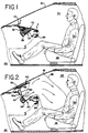
- FIG. 1 is a longitudinal cross-sectional view of a motor vehicle illustrating a serviceable, tethered cover airbag system in accordance with the present invention and shown with the cover in a closed position over a panel opening while the airbag is in deflated condition;
- FIG. 2 is a longitudinal cross-sectional view similar to FIG. 1 illustrating in animated fashion emergency deployment of the airbag with the cover in an open position while tethered so as to be positively retained a limited distance away from the panel opening;
- FIG. 3 is an underside view of a cover in accordance with the features of the present invention;
- FIG. 4 is an enlarged, fragmentary cross-sectional view similar to that of FIG. 1 showing the cover in a closed position covering the panel opening with the airbag in a deflated, stored condition ready for deployment;
- FIG. 5 is a perspective, animated view of a detachable connector for a cover and tether combination shown in a disconnected condition as used for permitting the cover to be detached from the tether for servicing of the system and/or repair and replacement of the cover;
- FIG. 6 is a view illustrating the connector and tether combination of FIG. 5 with the tether and cover interconnected together;
- FIG. 7 is a view of a portion of the underside of a tether and cover combination utilizing another embodiment of a detachable connector therebetween; and
- FIG. 8 is a view of a portion of the underside of a tether and cover combination utilizing yet another embodiment of a detachable connector therebetween.
- Referring now more particularly to the drawings, in FIGS. 1-4 is illustrated a
motor vehicle 20 having apassenger compartment 22 for accommodating aperson 24 in seated position on avehicle seat 26. Forward of theoccupant 24, thevehicle 20 includes adashboard 28 and apanel 30 having an enlargedopening 32 spaced directly above an airbag and inflator assembly generally indicated by thereference numeral 34. The airbag andinflator assembly 34 includes a housing orcanister 36 fixedly mounted in place beneath thepanel 30 and theopening 32. Anairbag 38 in deflated condition is stored and contained within thehousing 36 until deployed as illustrated in FIG. 2 to protect thevehicle occupant 24 from injury in an accident. - The
panel opening 32 is normally closed by amovable cover 40, which as shown in FIGS. 1 and 4 forms part of the upper surface of thepanel 30 above theopening 32. When theairbag 38 is inflated during a crash or emergency and expands outwardly, thecover 40 is rapidly moved away from the panel opening 32 permitting the expanding airbag to rapidly inflate as shown in FIG. 2. When airbag deployment occurs, thecover 40 if otherwise unrestrained or untethered could bounce off awindshield 42 or other interior surface inpassenger compartment 22. - Referring to FIG. 4, the
cover 40 includes anouter skin 44 formed of molded resinous plastic material and aninner skin 46 also formed of relatively thick resinous plastic material to provide strength and integrity for thecover 40 overall so that break up or fracture of the cover into pieces does not occur upon airbag deployment. - As can be seen from FIGS. 3 and 4, a number of
integral ribs 48 are molded into theinner skin 46 for stiffening purposes and a layer offoam 50 is bonded between the inner andouter skins cover 40 to provide a strong and lightweight body. Normally thecover 40 is retained in a closed position (FIG. 1) directly above and over theopening 32 by a plurality of pins orspring latch elements 52 which are locked into openings 54 (FIG. 4) provided in a lower flange 30a of thepanel 30, around the edge of the opening 32. Until theairbag 38 is deployed, thecover 40 acts as an integrated part of thepanel 30 and at the same time protects theairbag assembly 34 from damage and limits access thereto. - In accordance with the present invention, one or more tethers of strong, flexible material such as a
stranded metal cable 60, "Nylon" webbing, seat belt type material or the like is interconnected between the underside of thecover 40 and either the housing orcanister 36 of theairbag inflator assembly 34 or, as schematically shown, the underside ofpanel 30. Inner ends of theflexible cable tethers 60 are interconnected to the upper sidewall of the housing orcanister 36 by means of metal or plastic clips 62 (FIGS. 4 and 6). - Referring now specifically to FIGS. 3 and 4, the
inner skin 46 of thecover 40 is formed with an elongated, generallyrectangular compartment 64 therein in order to accommodate astiffening bar 66 formed of metal or other suitable stiff and strong material such as resinous plastic. As best shown in FIGS. 5 and 6, an outer end of eachcable tether 60 is provided with a swaged on,cylindrical cross-pin 61 of short length adapted to be detachably interconnected to a clevis type,connector 65 having a relativelylarge base 65a of square or rectangular shape secured to the lower face of the stiffeningbar 66 with appropriate fasteners such as headed rivets or bolts (not shown) extended through alignedholes 63 in thebase 65a and thebar 66. - In accordance with the present invention, the
clevis type connectors 65 include a pair of spaced apart, parallel, integrally formed, dependingflanges flange circular opening 67 adjacent the central portion thereof having a diameter slightly larger than that of the cross-pin 61 on thecable tether 60. Theopenings 67 in each pair of facingflanges - The
base 65a andflanges connector 65 are preferably formed of strong lightweight metal in a casting operation and inside faces of the flanges are spaced apart by a distance slightly greater than the diameter of thecable tether 60 to accommodate the cable between the flanges when interconnected as shown in FIG. 6. In order to permit the cable tethers 60 to be detachably connected to theconnectors 65 for easy interconnection and disconnection when required, theflange 65b is formed with a slot 69 having an open mouth at the outer end on the edge of the flange. The open mouth of the slot 69 is wide enough to accommodate the diameter of thecable tether 60 when the tether is inserted into the slot from outside the flange and moved in a direction coaxial with the cross-pin along thecenterline 71 of thecircular openings 67. - An inner end of each slot 69 opens into the
circular opening 67 of theflange 65b and once acable tether 60 is inserted into the space between theflanges axis 71 so that the facing inside surfaces of theflanges cylindrical opening 67 of the flanges. - As illustrated in FIG. 4, the
connectors 65 are attached to thestiffener bar 66 with the open mouth of the slots 69 facing toward the passenger oroccupant 24 and the cable tethers 60 extend in an opposite direction toward the forward end of the vehicle as shown in FIGS. 1, 2 and 4. When it is desired to service components of theairbag system 34 below thecover 40 or when it is desired to remove and replace or repair a defective, damaged orunsightly cover 40, thecover 40 is withdrawn upwardly from theopening 32 in thepanel 30 to expose theflanges connectors 65 which project downwardly throughslots 64a provided in the bottom wall of thecompartment 64 formed in the inner skin orwall 46 of thecover 40. When theflanges flanges 65a and the cables andcross-pins 61 are displaced along theaxis 71 until free and clear of theflanges cover 40 and the cable tethers 60 is completed. - The formed
housing 64 in theinner skin 46 of the cover is provided with theslots 64a in the bottom wall at appropriate intervals along the length thereof to accommodate the number ofconnectors 65 andcable tethers 60 that are used in a particular system. When theairbag 38 is deployed and thecover 40 is ejected away from theopening 32 in thepanel 30, the force exerted by the cable tethers 60 while in a taut condition (FIG. 2) is spread from thebases 65a of theconnectors 65 to the stiffeningbar 66 which are over a substantial portion of the length of thecover 40. This attachment arrangement greatly reduces the stress exerted by eachcable tether 60 on thecover 40 during deployment of theairbag 38 and normally prevents fracture of thecover 40 into pieces or fragments which could become projectiles causing damage or injury. - It should also be noted that the number of cable tethers 60 required for a
particular panel 60 may be increased if needed. For an exceptionally long cover, 40 three rather than two tethers may be provided or the number of tethers may be decreased to one in some instances. In any case, thebases 65a of theconnector 65 transmit and spread the load to the stiffeningbar 66 which is positively contained between the inside wall orskin 46 and the outside wall orskin 44 in thefoam 50 ofcover 40. - Referring now to FIG. 7, therein is illustrated an alternate embodiment of a
detachable connector 65A for use with atether 60A formed of flexible webbing of "Nylon" plastic stranded material. Thedetachable connector 65A includes a generally rectangular metal orplastic housing 75 of hollow tubular cross-section having rectangular openings 75a and 75b at opposite ends sized to accommodate amiddle section 77 of anelongated metal tongue 78 havingdeflectable fingers 79 at the outer end portion. When thefingers 79 are pinched together toward acentral slot 80 they can pass through the openings 75a and 75b of the housing. At an opposite end portion, thetongue 78 has anenlarged collar portion 81 which acts as a stop to limit further insertion of the tongue into the housing and which is permanently attached to thetether 60A which is looped through a slot therein. - Outer, oppositely facing edges of the
fingers 79 of thetongue 78 act as cam surfaces which engage opposite edges of the entrance opening 75a of thehousing 75 as the tongue is initially inserted to cam the fingers together toward thecentral slot 80. When full insertion of thetongue 78 in thehousing 75 is accomplished,inner stop portions 79a at the base of eachfinger 79, engage thehousing 75 outside the end of the opening 75b to lock thetongue 78 in place in the housing and thus securely connect thetether 60A to thecover 40 in a detachable connection. - When it is desired to disconnect the
tether 60A and thecover 40, thefingers 79 are pinched together toward thecenter slot 80 while a pulling force is exerted on thetether 60A to withdraw thetongue 78 from thehousing 75. Thehousings 75 are permanently attached to the stiffeningbar 66 and the bottom wall of thehousing 64 by means of fasteners such as rivets or bolts (not shown) which pass through aligned openings in the stiffening bar, housing wall and bottom wall of theconnector housing 75. - Referring now to FIG. 8, therein is illustrated yet another alternate embodiment of a detachable connector 65B for use with a
tether 60B such as a "seat belt" type webbing common to autos and airplanes. The connector 65B includes a generally rectangular, metal orplastic housing 85 of hollow tubular, generally rectangular cross-section having a rectangular entrance opening 85a at one end sized to accommodate amiddle section 87 of atongue 88. - The
tongue 88 is generally similar both in structure and function to thetongue 78 of the prior embodiment except that an outer free end 89 of the tongue does not project outside of thehousing 85 which is closed by anend wall 85b opposite the entrance opening 85a. The outer end portion of thetongue 88 is formed with acentral slot 90 formingdeflectable fingers 91 which are pinched toward theslot 90 by facing inside, oppositeside edge walls 85c of therectangular housing 85 as the tongue is inserted. - The opposite
side edge walls 85c haveopen slots 92 at their ends adjacent thehousing end wall 85b, in order to accommodate roundedouter cam elements 93 on the outer edge of thefingers 91 which extend into theslots 92 to lock and hold thetongue 88 in place in a detachable connection within thehousing 85. For release of thetongue 88 to disconnect thetether 60B and thepanel 40, therounded cam elements 93 are pinched toward thecenter slot 90 while a pull out force is exerted on the tongue from thetether 60B. As this occurs, thecam elements 93 on thefingers 91 pass along the inside surfaces of the oppositeside edge walls 85c of thehousing 85 until thetongue 88 is clear. Insertion of thetongue 88 to interconnect or reconnect thetether 60B and thecover 40 is accomplished simply by inserting and pushing thetongue 88 inwardly into thehousing 85 through the entrance opening 85a until thecam elements 93 reach the sideedge wall slots 92 permitting thefingers 91 to spring apart to lock the tongue in place.
Claims (12)
- An airbag system (34) for motor vehicles (20) and the like, having a panel (30) formed with an opening (32) in the vicinity of an occupant's seat (26), and including an inflatable airbag (38) and housing (36) for holding said airbag while in a deflated condition, said housing having an open end aligned with said panel opening to permit said airbag to pass outwardly when deployed to provide cushioning support for an occupant (24) of said seat, comprising:
cover means (40) closing said panel opening for protecting said airbag and movable to uncover said opening during airbag deployment;
flexible tether means, including an elongated flexible member (60), interconnected between said cover means and at least one of said panel and said housing for limiting the movement of said cover means away from said panel during airbag deployment;
attachment means (61, 65) connecting said tether means and said cover means, the connection being releasable for permitting removal or replacement of said cover means without disturbance of the connection of said tether to said panel or housing;
said attachment means comprising detachably interconnectable male and female connector elements, one of said elements (61) being fixedly attached to said tether means and the other of said elements (65) being fixedly attached to said cover means. - An airbag system according to claim 1 wherein said tether means (60A, 60B) comprises a webbing of woven material having an end portion looped around one of said connector elements.
- An airbag system according to claim 2 wherein said end portion of said tether means is looped around said male connector element (78, 88).
- An airbag system according to claim 1 wherein said tether means comprises cable means (60) formed of strand elements wound together.
- An airbag system according to any preceding claim wherein said male connector element (78, 88) includes a plurality of elongated fingers (79, 91) having free outer ends, at least one said free outer end being deflectable towards another and slidable longitudinally when so deflected in said female connector element (75, 85) to interconnect said tether means (60A, 60B) and said cover means (40).
- An airbag system according to claim 5 wherein at least one of said elongated fingers (79, 91) has retainer means (79a, 93) adjacent said free outer end for securing said finger against longitudinal retraction from said female connector (75, 85) when released from deflection.
- A tethered cover, for use with an airbag system for motor vehicles having a panel formed with an opening in the vicinity of an occupant's seat and a housing for an inflatable airbag aligned with said opening to permit said airbag to pass through said opening when it is deployed, comprising:
cover means (40) closing said opening (32) in said panel (30) for protecting said airbag (38) and movable to uncover said opening during airbag deployment;
flexible tether means, including an elongated flexible member (60, 60A, 60B), capable of detachably interconnecting said cover means and at least one of said panel and said housing for limiting the movement of said cover means away from said panel during airbag deployment; and
releasable attachment means (61, 65, 75, 78, 85, 88) connecting said tether means and said cover means and releasable to permit disconnection and reconnection of said cover means and said tether means;
said attachment means comprising detachably interconnectable male and female connectors, said male connector (61, 78, 88) being longitudinally slidable in said female connector (65, 75, 85) to a position at which it forms a connection with said female connector, one of said connectors (61, 78, 88) being fixedly attached to said tether means and the other of said elements (65, 75, 85) fixedly attached to said cover means. - A tethered cover according to claim 7 wherein said tether means comprises a webbing of woven stranded plastics material (60A, 60B) having an end portion looped around one of said connectors.
- A tethered cover according to claim 8 wherein said end portion (60A, 60B) of said tether means is looped around said male connector (78, 88).
- A tethered cover according to claim 7 wherein said tether means comprises cable means formed of a plurality of strand elements.
- A tethered cover according to any one of claims 7 to 10 wherein said male connector (78, 88) includes a plurality of spaced apart opposite elongated fingers (79, 91) having free outer ends, at least one free outer end of a finger being deflectable laterally toward an opposite finger, said male connector when so deflected being slidable longitudinally of said fingers to fit in said female connector (75, 85) to interconnect said tether means (60A, 60B) and said cover means (40).
- A tethered cover according to claim 11 wherein at least one of said elongated fingers (79, 91) has cam means (79a, 93) adjacent said free outer end for securing said finger against longitudinal retraction from said female connector (75, 85) after release from said lateral deflection.
Applications Claiming Priority (2)
| Application Number | Priority Date | Filing Date | Title |
|---|---|---|---|
| US286795 | 1994-08-05 | ||
| US08/286,795 US6053527A (en) | 1994-08-05 | 1994-08-05 | Airbag system with serviceable tethered cover |
Publications (2)
| Publication Number | Publication Date |
|---|---|
| EP0695671A1 true EP0695671A1 (en) | 1996-02-07 |
| EP0695671B1 EP0695671B1 (en) | 1998-11-11 |
Family
ID=23100189
Family Applications (1)
| Application Number | Title | Priority Date | Filing Date |
|---|---|---|---|
| EP95305387A Expired - Lifetime EP0695671B1 (en) | 1994-08-05 | 1995-08-01 | Airbag system with serviceable tethered cover |
Country Status (4)
| Country | Link |
|---|---|
| US (1) | US6053527A (en) |
| EP (1) | EP0695671B1 (en) |
| JP (1) | JP3021131U (en) |
| DE (1) | DE69505909T2 (en) |
Cited By (11)
| Publication number | Priority date | Publication date | Assignee | Title |
|---|---|---|---|---|
| EP0872390A1 (en) * | 1996-11-07 | 1998-10-21 | Toyota Jidosha Kabushiki Kaisha | Arrangement and construction of crew protective device for automobile |
| EP0873916A1 (en) * | 1997-04-24 | 1998-10-28 | Rover Group Limited | An airbag housing assembly |
| DE19828163A1 (en) * | 1998-06-24 | 1999-12-30 | Volkswagen Ag | Restraint unit for trim cover over airbag device |
| US6443483B2 (en) | 1999-12-30 | 2002-09-03 | Trw Occupant Restraint Systems Gmbh & Co. Kg | Gas bag module |
| EP1055567A3 (en) * | 1999-05-24 | 2002-11-27 | Ford Motor Company | Inflatable restraint system door assembly and tether to limit the movement of the door |
| GB2388082A (en) * | 2002-05-02 | 2003-11-05 | David J Salt | Flexibly tethered air bag cover |
| EP1487673A2 (en) * | 2002-03-27 | 2004-12-22 | Collins & Aikman Automotive Company Inc. | Dynamic sliding tether arrangement for airbag door |
| FR2902728A1 (en) * | 2006-06-21 | 2007-12-28 | Faurecia Interieur Ind Snc | Motor vehicle fascia, has flap retained on fascia by connection device disposed at side of opening nearest to windscreen, where device has sufficient length to allow contact with windscreen at side of flap nearest to windscreen |
| WO2011116950A1 (en) * | 2010-03-24 | 2011-09-29 | Faurecia Interieur Industrie | Inflatable airbag arrangement in a dashboard, comprising a flap connected to the dashboard by means of a linear link |
| EP2687412B1 (en) * | 2012-07-17 | 2016-03-23 | Dalphi Metal España, S.A. | Cover for a gas bag module, a bag module with said cover, steering wheel and method of manufacturing said cover |
| US9821747B2 (en) | 2014-10-09 | 2017-11-21 | Newfrey Llc | Tethered fastener and related methods |
Families Citing this family (28)
| Publication number | Priority date | Publication date | Assignee | Title |
|---|---|---|---|---|
| DE10010589C1 (en) * | 2000-03-03 | 2001-07-19 | Autoliv Dev | Airbag module for automobile has drive block for removal of cover for airbag module in crash situation |
| US6325415B1 (en) * | 2000-05-31 | 2001-12-04 | Trw Vehicle Safety Systems Inc. | Air bag module with tethered door |
| US6733032B2 (en) * | 2001-03-12 | 2004-05-11 | Delphi Technologies, Inc. | Air bag cover assembly |
| US7178850B2 (en) * | 2005-02-09 | 2007-02-20 | Termax Corporation | Tethered fastener apparatus and method |
| DE20112342U1 (en) * | 2001-07-26 | 2001-10-31 | Breed Automotive Tech | Fastening element for a curtain airbag |
| ATE389566T1 (en) * | 2001-12-03 | 2008-04-15 | Inova Gmbh Tech Entwicklungen | AIRBAG DEVICE AND OPERATING METHOD THEREOF |
| US6517108B1 (en) | 2002-01-02 | 2003-02-11 | Ford Global Technologies, Inc. | Pyrotechnic air bag stitch vent |
| US6736425B2 (en) | 2002-01-28 | 2004-05-18 | Ford Global Technologies, Llc | System for venting an air bag module |
| US6746045B2 (en) | 2002-04-05 | 2004-06-08 | Ford Global Technologies, Llc | Air bag inflator gas venting system |
| US6802528B2 (en) | 2002-04-05 | 2004-10-12 | Ford Global Technologies, Llc | Air bag cushion energy diverter |
| US7461861B2 (en) * | 2002-07-22 | 2008-12-09 | Ramesh Keshavaraj | Profile tuner panel for inflatable cushions |
| DK2730721T3 (en) | 2004-05-10 | 2019-08-12 | Zipwall Llc | Partition mount with integrated plunger assembly |
| US7178205B2 (en) * | 2004-08-10 | 2007-02-20 | Newfrey Llc | Multiple engagement joint tethered fastener |
| US7155783B2 (en) * | 2004-08-10 | 2007-01-02 | Newfrey Llc | Multiple engagement joint tethered fastener |
| JP4670629B2 (en) * | 2005-12-22 | 2011-04-13 | マツダ株式会社 | Instrument panel structure with airbag unit |
| US7543845B2 (en) * | 2006-01-04 | 2009-06-09 | Visteon Global Technologies, Inc. | Self-closing airbag door assembly |
| JP2011000962A (en) * | 2009-06-18 | 2011-01-06 | Honda Motor Co Ltd | Airbag device of saddle-riding type vehicle |
| FR2957871B1 (en) * | 2010-03-24 | 2012-04-20 | Faurecia Interieur Ind | INFLATABLE SAFETY CUSHION COMPONENT JOINED ON A DASHBOARD BY AN AGENCY LINK TO RELEASE AN ADDITIONAL LENGTH OF LINK ON OPENING THIS COMPONENT |
| DE102010051421A1 (en) * | 2010-11-17 | 2012-05-24 | Trw Automotive Gmbh | System for restraining front seat passenger in motor car during accident, has supporting structure provided on side of gas bag and arranged under instrument panel before activation of gas bag, where side faces windscreen |
| EP3027482B1 (en) | 2013-07-31 | 2021-09-15 | Rail Vision Ltd | System and method for obstacle identification and avoidance |
| US9663962B1 (en) | 2014-01-17 | 2017-05-30 | Zipwall, Llc. | Pole mount and methods of installation and application |
| US9669788B2 (en) * | 2014-10-03 | 2017-06-06 | GM Global Technology Operations LLC | Knee airbag for motor vehicle |
| US10428539B2 (en) | 2015-06-03 | 2019-10-01 | Zipwall, Llc. | Mounting unit for partition mount |
| US10377336B2 (en) * | 2017-11-13 | 2019-08-13 | Ford Global Technologies, Llc | Molded air bag chute with door reinforced by hollow channel |
| JP6689894B2 (en) * | 2018-01-15 | 2020-04-28 | 本田技研工業株式会社 | Vehicle airbag device |
| US10946825B2 (en) * | 2018-12-04 | 2021-03-16 | Ford Global Technologies, Llc | Airbag assembly |
| US11912229B2 (en) | 2021-03-30 | 2024-02-27 | Honda Motor Co., Ltd. | Lid for airbag tether deployment in vehicles |
| KR20230058972A (en) * | 2021-10-25 | 2023-05-03 | 현대모비스 주식회사 | Knee air bag |
Citations (17)
| Publication number | Priority date | Publication date | Assignee | Title |
|---|---|---|---|---|
| US3822894A (en) | 1970-10-24 | 1974-07-09 | Petri Ag | Steering wheel with built-in air cushion |
| US3944250A (en) | 1971-12-03 | 1976-03-16 | Daimler-Benz Aktiengesellschaft | Automatically inflatable gas cushion for the protection of the passengers of vehicles |
| US4893833A (en) | 1988-09-08 | 1990-01-16 | Tip Engineering Group, Inc. | Closure for an air bag deployment opening |
| US4911471A (en) | 1988-02-09 | 1990-03-27 | Nissan Motor Co., Ltd. | Arrangement of air-bag device in motor vehicle |
| DE3843686A1 (en) | 1988-12-23 | 1990-06-28 | Bayerische Motoren Werke Ag | Cover for an airbag arrangement in a motor vehicle |
| US4964653A (en) | 1989-08-24 | 1990-10-23 | Davidson Textron Inc. | Self-skinned foam component for an inflatable restraint door assembly |
| EP0415362A2 (en) | 1989-08-30 | 1991-03-06 | Mazda Motor Corporation | Air bag system for vehicle |
| US5064217A (en) | 1989-08-08 | 1991-11-12 | Toyoda Gosei Co., Ltd. | Cover for air bag unit |
| US5072967A (en) | 1990-07-12 | 1991-12-17 | Davidson Textron Inc. | Instrument panel with invisible airbag deployment door |
| US5096221A (en) | 1991-02-21 | 1992-03-17 | Davidson Textron Inc. | Air bag door with plural substrates |
| US5195776A (en) | 1990-03-27 | 1993-03-23 | Mazda Motor Corporation | Air bag installation |
| US5199739A (en) | 1990-09-05 | 1993-04-06 | Toyota Jidosha Kabushiki Kaisha | Air bag cover opening mechanism for use in vehicle |
| US5211421A (en) | 1992-02-24 | 1993-05-18 | General Motors Corporation | Air bag cover door retainer |
| US5219177A (en) | 1992-06-19 | 1993-06-15 | General Motors Corporation | Releasable latch for air bag deployment door |
| US5242191A (en) | 1991-01-18 | 1993-09-07 | Trw Vehicle Safety Systems Inc. | Tethered air bag cover |
| US5398960A (en) * | 1994-02-01 | 1995-03-21 | Morton International, Inc. | Airbag module doors having slip-in and snap-in tether attachments |
| US5398959A (en) * | 1992-02-19 | 1995-03-21 | General Motors Corporation | Panel cover door attachment for inflatable occupant restraint |
Family Cites Families (9)
| Publication number | Priority date | Publication date | Assignee | Title |
|---|---|---|---|---|
| US2099655A (en) * | 1935-03-20 | 1937-11-16 | United Carr Fastener Corp | Mounting bracket and installation thereof |
| GB2218698A (en) * | 1988-01-19 | 1989-11-22 | Talley Automotive Prod | Inflator device for deployment of a motor vehicle passenger passive restraint system |
| JP2936585B2 (en) * | 1989-07-18 | 1999-08-23 | タカタ株式会社 | Airbag device |
| US5082310A (en) * | 1989-11-06 | 1992-01-21 | Tip Engineering Group, Inc. | Arrangement for providing an air bag deployment opening |
| US5044663A (en) * | 1990-02-12 | 1991-09-03 | Solvay Automotive, Inc. | Blow molded airbag with fabric reinforcements |
| JPH04310450A (en) * | 1991-04-09 | 1992-11-02 | Toyota Motor Corp | Air bag device |
| US5211422A (en) * | 1991-08-29 | 1993-05-18 | General Motors Corporation | Occupant restraint system |
| JPH05338513A (en) * | 1992-06-09 | 1993-12-21 | Toyota Motor Corp | Cover mounting structure for side air bag device |
| US5332257A (en) * | 1993-08-09 | 1994-07-26 | Morton International, Inc. | Tether retention system for airbag module cover |
-
1994
- 1994-08-05 US US08/286,795 patent/US6053527A/en not_active Expired - Fee Related
-
1995
- 1995-07-31 JP JP1995007887U patent/JP3021131U/en not_active Expired - Lifetime
- 1995-08-01 EP EP95305387A patent/EP0695671B1/en not_active Expired - Lifetime
- 1995-08-01 DE DE69505909T patent/DE69505909T2/en not_active Expired - Fee Related
Patent Citations (18)
| Publication number | Priority date | Publication date | Assignee | Title |
|---|---|---|---|---|
| US3822894A (en) | 1970-10-24 | 1974-07-09 | Petri Ag | Steering wheel with built-in air cushion |
| US3944250A (en) | 1971-12-03 | 1976-03-16 | Daimler-Benz Aktiengesellschaft | Automatically inflatable gas cushion for the protection of the passengers of vehicles |
| US4911471A (en) | 1988-02-09 | 1990-03-27 | Nissan Motor Co., Ltd. | Arrangement of air-bag device in motor vehicle |
| US4893833A (en) | 1988-09-08 | 1990-01-16 | Tip Engineering Group, Inc. | Closure for an air bag deployment opening |
| DE3843686A1 (en) | 1988-12-23 | 1990-06-28 | Bayerische Motoren Werke Ag | Cover for an airbag arrangement in a motor vehicle |
| US5064217A (en) | 1989-08-08 | 1991-11-12 | Toyoda Gosei Co., Ltd. | Cover for air bag unit |
| US4964653A (en) | 1989-08-24 | 1990-10-23 | Davidson Textron Inc. | Self-skinned foam component for an inflatable restraint door assembly |
| US5150919A (en) | 1989-08-30 | 1992-09-29 | Mazda Motor Corporation | Air bag system for vehicle |
| EP0415362A2 (en) | 1989-08-30 | 1991-03-06 | Mazda Motor Corporation | Air bag system for vehicle |
| US5195776A (en) | 1990-03-27 | 1993-03-23 | Mazda Motor Corporation | Air bag installation |
| US5072967A (en) | 1990-07-12 | 1991-12-17 | Davidson Textron Inc. | Instrument panel with invisible airbag deployment door |
| US5199739A (en) | 1990-09-05 | 1993-04-06 | Toyota Jidosha Kabushiki Kaisha | Air bag cover opening mechanism for use in vehicle |
| US5242191A (en) | 1991-01-18 | 1993-09-07 | Trw Vehicle Safety Systems Inc. | Tethered air bag cover |
| US5096221A (en) | 1991-02-21 | 1992-03-17 | Davidson Textron Inc. | Air bag door with plural substrates |
| US5398959A (en) * | 1992-02-19 | 1995-03-21 | General Motors Corporation | Panel cover door attachment for inflatable occupant restraint |
| US5211421A (en) | 1992-02-24 | 1993-05-18 | General Motors Corporation | Air bag cover door retainer |
| US5219177A (en) | 1992-06-19 | 1993-06-15 | General Motors Corporation | Releasable latch for air bag deployment door |
| US5398960A (en) * | 1994-02-01 | 1995-03-21 | Morton International, Inc. | Airbag module doors having slip-in and snap-in tether attachments |
Cited By (18)
| Publication number | Priority date | Publication date | Assignee | Title |
|---|---|---|---|---|
| EP0872390A1 (en) * | 1996-11-07 | 1998-10-21 | Toyota Jidosha Kabushiki Kaisha | Arrangement and construction of crew protective device for automobile |
| EP0872390B1 (en) * | 1996-11-07 | 2004-05-19 | Toyota Jidosha Kabushiki Kaisha | Arrangement and construction of crew protective device for automobile |
| EP0873916A1 (en) * | 1997-04-24 | 1998-10-28 | Rover Group Limited | An airbag housing assembly |
| US6145870A (en) * | 1997-04-24 | 2000-11-14 | Rover Group Limited | Airbag housing assembly |
| US6402188B1 (en) * | 1998-06-24 | 2002-06-11 | Volkswagen | Retaining device for a paneling element covering an airbag arrangement |
| DE19828163A1 (en) * | 1998-06-24 | 1999-12-30 | Volkswagen Ag | Restraint unit for trim cover over airbag device |
| EP1055567A3 (en) * | 1999-05-24 | 2002-11-27 | Ford Motor Company | Inflatable restraint system door assembly and tether to limit the movement of the door |
| US6443483B2 (en) | 1999-12-30 | 2002-09-03 | Trw Occupant Restraint Systems Gmbh & Co. Kg | Gas bag module |
| EP1487673A4 (en) * | 2002-03-27 | 2008-12-10 | Collins & Aikman Automotive Co | Dynamic sliding tether arrangement for airbag door |
| EP1487673A2 (en) * | 2002-03-27 | 2004-12-22 | Collins & Aikman Automotive Company Inc. | Dynamic sliding tether arrangement for airbag door |
| GB2388082A (en) * | 2002-05-02 | 2003-11-05 | David J Salt | Flexibly tethered air bag cover |
| FR2902728A1 (en) * | 2006-06-21 | 2007-12-28 | Faurecia Interieur Ind Snc | Motor vehicle fascia, has flap retained on fascia by connection device disposed at side of opening nearest to windscreen, where device has sufficient length to allow contact with windscreen at side of flap nearest to windscreen |
| WO2011116950A1 (en) * | 2010-03-24 | 2011-09-29 | Faurecia Interieur Industrie | Inflatable airbag arrangement in a dashboard, comprising a flap connected to the dashboard by means of a linear link |
| FR2957872A1 (en) * | 2010-03-24 | 2011-09-30 | Faurecia Interieur Ind | INFLATABLE SAFETY CUSHION ARRANGEMENT IN A DASHBOARD COMPRISING A FLAP CONNECTED TO THE DASHBOARD BY A LINEAR LINK. |
| US8657328B2 (en) | 2010-03-24 | 2014-02-25 | Faurecia Interieur Industrie | Arrangement of an inflatable airbag in an instrument panel comprising a flap connected to the instrument panel by a linear tether |
| EP2687412B1 (en) * | 2012-07-17 | 2016-03-23 | Dalphi Metal España, S.A. | Cover for a gas bag module, a bag module with said cover, steering wheel and method of manufacturing said cover |
| EP2687413B1 (en) * | 2012-07-17 | 2016-03-23 | Dalphi Metal España, S.A. | Cover for a gas bag module, a bag module with said cover, steering wheel and method of manufacturing said cover |
| US9821747B2 (en) | 2014-10-09 | 2017-11-21 | Newfrey Llc | Tethered fastener and related methods |
Also Published As
| Publication number | Publication date |
|---|---|
| EP0695671B1 (en) | 1998-11-11 |
| DE69505909T2 (en) | 1999-06-02 |
| DE69505909D1 (en) | 1998-12-17 |
| US6053527A (en) | 2000-04-25 |
| JP3021131U (en) | 1996-02-16 |
Similar Documents
| Publication | Publication Date | Title |
|---|---|---|
| US6053527A (en) | Airbag system with serviceable tethered cover | |
| US5472228A (en) | Break-away fastening system for air bag deployment doors | |
| US5460401A (en) | Airbag system with tethered cover | |
| JP3042494U (en) | Airbag module | |
| EP0743230B1 (en) | Break-away fastening system for air bag deployment doors | |
| EP0638464B1 (en) | Tether retention system for airbag module cover | |
| US5211421A (en) | Air bag cover door retainer | |
| EP0722862B1 (en) | Cover for a panel opening in an air bag inflator system | |
| US5474324A (en) | Tethered cover airbag system | |
| EP0799750B1 (en) | Seat mounted air bag module | |
| US5647607A (en) | Tether attachment apparatus for air bag cover | |
| HU213434B (en) | Automotive vehicle including a security arrangement provided with an inflatable protective bag | |
| US20030111828A1 (en) | Compact tethering system and method for an inflatable curtain | |
| US5498027A (en) | Seamless door for air bag module | |
| EP0489174A1 (en) | Air bag device for assistant-driver's seat | |
| CN110871766A (en) | Inflatable restraint device for a vehicle | |
| US5971427A (en) | Side impact air bag clamshell-wrap around strap closure | |
| US5398961A (en) | Flexible strap attachment method and apparatus for passenger air bag module cover | |
| JP3051225U (en) | Cover and housing assembly | |
| EP0709258A1 (en) | Airbag cover retainer | |
| US20050189739A1 (en) | Airbag retention collar for airbag module assembly | |
| EP2149480A1 (en) | Improvements in curtain airbags | |
| JP3385905B2 (en) | Installation structure of vehicle occupant protection system | |
| US6076849A (en) | Motor vehicle dashboard assembly | |
| KR200144273Y1 (en) | Front passenger's airbag cover |
Legal Events
| Date | Code | Title | Description |
|---|---|---|---|
| PUAI | Public reference made under article 153(3) epc to a published international application that has entered the european phase |
Free format text: ORIGINAL CODE: 0009012 |
|
| AK | Designated contracting states |
Kind code of ref document: A1 Designated state(s): DE FR GB IT |
|
| 17P | Request for examination filed |
Effective date: 19960513 |
|
| 17Q | First examination report despatched |
Effective date: 19970131 |
|
| GRAG | Despatch of communication of intention to grant |
Free format text: ORIGINAL CODE: EPIDOS AGRA |
|
| GRAG | Despatch of communication of intention to grant |
Free format text: ORIGINAL CODE: EPIDOS AGRA |
|
| GRAG | Despatch of communication of intention to grant |
Free format text: ORIGINAL CODE: EPIDOS AGRA |
|
| GRAH | Despatch of communication of intention to grant a patent |
Free format text: ORIGINAL CODE: EPIDOS IGRA |
|
| GRAH | Despatch of communication of intention to grant a patent |
Free format text: ORIGINAL CODE: EPIDOS IGRA |
|
| RAP1 | Party data changed (applicant data changed or rights of an application transferred) |
Owner name: AUTOLIV ASP, INC. |
|
| GRAA | (expected) grant |
Free format text: ORIGINAL CODE: 0009210 |
|
| AK | Designated contracting states |
Kind code of ref document: B1 Designated state(s): DE FR GB IT |
|
| PG25 | Lapsed in a contracting state [announced via postgrant information from national office to epo] |
Ref country code: IT Free format text: LAPSE BECAUSE OF FAILURE TO SUBMIT A TRANSLATION OF THE DESCRIPTION OR TO PAY THE FEE WITHIN THE PRE;WARNING: LAPSES OF ITALIAN PATENTS WITH EFFECTIVE DATE BEFORE 2007 MAY HAVE OCCURRED AT ANY TIME BEFORE 2007. THE CORRECT EFFECTIVE DATE MAY BE DIFFERENT FROM THE ONE RECORDED.SCRIBED TIME-LIMIT Effective date: 19981111 |
|
| REF | Corresponds to: |
Ref document number: 69505909 Country of ref document: DE Date of ref document: 19981217 |
|
| ET | Fr: translation filed | ||
| PLBE | No opposition filed within time limit |
Free format text: ORIGINAL CODE: 0009261 |
|
| STAA | Information on the status of an ep patent application or granted ep patent |
Free format text: STATUS: NO OPPOSITION FILED WITHIN TIME LIMIT |
|
| 26N | No opposition filed | ||
| REG | Reference to a national code |
Ref country code: GB Ref legal event code: IF02 |
|
| PGFP | Annual fee paid to national office [announced via postgrant information from national office to epo] |
Ref country code: GB Payment date: 20040728 Year of fee payment: 10 |
|
| PGFP | Annual fee paid to national office [announced via postgrant information from national office to epo] |
Ref country code: FR Payment date: 20040819 Year of fee payment: 10 |
|
| PG25 | Lapsed in a contracting state [announced via postgrant information from national office to epo] |
Ref country code: GB Free format text: LAPSE BECAUSE OF NON-PAYMENT OF DUE FEES Effective date: 20050801 |
|
| GBPC | Gb: european patent ceased through non-payment of renewal fee |
Effective date: 20050801 |
|
| PG25 | Lapsed in a contracting state [announced via postgrant information from national office to epo] |
Ref country code: FR Free format text: LAPSE BECAUSE OF NON-PAYMENT OF DUE FEES Effective date: 20060428 |
|
| REG | Reference to a national code |
Ref country code: FR Ref legal event code: ST Effective date: 20060428 |
|
| PGFP | Annual fee paid to national office [announced via postgrant information from national office to epo] |
Ref country code: DE Payment date: 20061002 Year of fee payment: 12 |
|
| PG25 | Lapsed in a contracting state [announced via postgrant information from national office to epo] |
Ref country code: DE Free format text: LAPSE BECAUSE OF NON-PAYMENT OF DUE FEES Effective date: 20080301 |