EP0694740A2 - Combustion chamber - Google Patents
Combustion chamber Download PDFInfo
- Publication number
- EP0694740A2 EP0694740A2 EP95810442A EP95810442A EP0694740A2 EP 0694740 A2 EP0694740 A2 EP 0694740A2 EP 95810442 A EP95810442 A EP 95810442A EP 95810442 A EP95810442 A EP 95810442A EP 0694740 A2 EP0694740 A2 EP 0694740A2
- Authority
- EP
- European Patent Office
- Prior art keywords
- combustion chamber
- channel
- flow
- fuel
- stage
- Prior art date
- Legal status (The legal status is an assumption and is not a legal conclusion. Google has not performed a legal analysis and makes no representation as to the accuracy of the status listed.)
- Withdrawn
Links
Images


Classifications
-
- F—MECHANICAL ENGINEERING; LIGHTING; HEATING; WEAPONS; BLASTING
- F23—COMBUSTION APPARATUS; COMBUSTION PROCESSES
- F23C—METHODS OR APPARATUS FOR COMBUSTION USING FLUID FUEL OR SOLID FUEL SUSPENDED IN A CARRIER GAS OR AIR
- F23C13/00—Apparatus in which combustion takes place in the presence of catalytic material
-
- F—MECHANICAL ENGINEERING; LIGHTING; HEATING; WEAPONS; BLASTING
- F23—COMBUSTION APPARATUS; COMBUSTION PROCESSES
- F23C—METHODS OR APPARATUS FOR COMBUSTION USING FLUID FUEL OR SOLID FUEL SUSPENDED IN A CARRIER GAS OR AIR
- F23C6/00—Combustion apparatus characterised by the combination of two or more combustion chambers or combustion zones, e.g. for staged combustion
- F23C6/04—Combustion apparatus characterised by the combination of two or more combustion chambers or combustion zones, e.g. for staged combustion in series connection
- F23C6/042—Combustion apparatus characterised by the combination of two or more combustion chambers or combustion zones, e.g. for staged combustion in series connection with fuel supply in stages
-
- F—MECHANICAL ENGINEERING; LIGHTING; HEATING; WEAPONS; BLASTING
- F23—COMBUSTION APPARATUS; COMBUSTION PROCESSES
- F23R—GENERATING COMBUSTION PRODUCTS OF HIGH PRESSURE OR HIGH VELOCITY, e.g. GAS-TURBINE COMBUSTION CHAMBERS
- F23R3/00—Continuous combustion chambers using liquid or gaseous fuel
- F23R3/02—Continuous combustion chambers using liquid or gaseous fuel characterised by the air-flow or gas-flow configuration
- F23R3/04—Air inlet arrangements
- F23R3/10—Air inlet arrangements for primary air
- F23R3/12—Air inlet arrangements for primary air inducing a vortex
-
- F—MECHANICAL ENGINEERING; LIGHTING; HEATING; WEAPONS; BLASTING
- F23—COMBUSTION APPARATUS; COMBUSTION PROCESSES
- F23R—GENERATING COMBUSTION PRODUCTS OF HIGH PRESSURE OR HIGH VELOCITY, e.g. GAS-TURBINE COMBUSTION CHAMBERS
- F23R3/00—Continuous combustion chambers using liquid or gaseous fuel
- F23R3/02—Continuous combustion chambers using liquid or gaseous fuel characterised by the air-flow or gas-flow configuration
- F23R3/16—Continuous combustion chambers using liquid or gaseous fuel characterised by the air-flow or gas-flow configuration with devices inside the flame tube or the combustion chamber to influence the air or gas flow
-
- F—MECHANICAL ENGINEERING; LIGHTING; HEATING; WEAPONS; BLASTING
- F23—COMBUSTION APPARATUS; COMBUSTION PROCESSES
- F23R—GENERATING COMBUSTION PRODUCTS OF HIGH PRESSURE OR HIGH VELOCITY, e.g. GAS-TURBINE COMBUSTION CHAMBERS
- F23R3/00—Continuous combustion chambers using liquid or gaseous fuel
- F23R3/40—Continuous combustion chambers using liquid or gaseous fuel characterised by the use of catalytic means
-
- F—MECHANICAL ENGINEERING; LIGHTING; HEATING; WEAPONS; BLASTING
- F05—INDEXING SCHEMES RELATING TO ENGINES OR PUMPS IN VARIOUS SUBCLASSES OF CLASSES F01-F04
- F05B—INDEXING SCHEME RELATING TO WIND, SPRING, WEIGHT, INERTIA OR LIKE MOTORS, TO MACHINES OR ENGINES FOR LIQUIDS COVERED BY SUBCLASSES F03B, F03D AND F03G
- F05B2260/00—Function
- F05B2260/20—Heat transfer, e.g. cooling
- F05B2260/221—Improvement of heat transfer
- F05B2260/222—Improvement of heat transfer by creating turbulence
-
- F—MECHANICAL ENGINEERING; LIGHTING; HEATING; WEAPONS; BLASTING
- F23—COMBUSTION APPARATUS; COMBUSTION PROCESSES
- F23C—METHODS OR APPARATUS FOR COMBUSTION USING FLUID FUEL OR SOLID FUEL SUSPENDED IN A CARRIER GAS OR AIR
- F23C2900/00—Special features of, or arrangements for combustion apparatus using fluid fuels or solid fuels suspended in air; Combustion processes therefor
- F23C2900/07002—Premix burners with air inlet slots obtained between offset curved wall surfaces, e.g. double cone burners
-
- F—MECHANICAL ENGINEERING; LIGHTING; HEATING; WEAPONS; BLASTING
- F23—COMBUSTION APPARATUS; COMBUSTION PROCESSES
- F23C—METHODS OR APPARATUS FOR COMBUSTION USING FLUID FUEL OR SOLID FUEL SUSPENDED IN A CARRIER GAS OR AIR
- F23C2900/00—Special features of, or arrangements for combustion apparatus using fluid fuels or solid fuels suspended in air; Combustion processes therefor
- F23C2900/13002—Catalytic combustion followed by a homogeneous combustion phase or stabilizing a homogeneous combustion phase
-
- F—MECHANICAL ENGINEERING; LIGHTING; HEATING; WEAPONS; BLASTING
- F23—COMBUSTION APPARATUS; COMBUSTION PROCESSES
- F23R—GENERATING COMBUSTION PRODUCTS OF HIGH PRESSURE OR HIGH VELOCITY, e.g. GAS-TURBINE COMBUSTION CHAMBERS
- F23R2900/00—Special features of, or arrangements for continuous combustion chambers; Combustion processes therefor
- F23R2900/03341—Sequential combustion chambers or burners
Definitions
- the present invention relates to a combustion chamber according to the preamble of claim 1.
- the invention seeks to remedy this.
- the invention as characterized in the claims, is based on the object, in a combustion chamber of the type mentioned, to minimize all pollutant emissions occurring during combustion, regardless of the type of fuel used.
- the aim here is to keep the mixture constant in the first stage so that UHC and CO emissions can be prevented.
- the mixer used in the first stage mixes fuel and air evenly, whereby in the case of oil, droplet evaporation takes place. If a premix burner according to EP-A1-0 321 809 is used for the above-mentioned mixing, then this undergoes a modification regarding the aerodynamics, which is manifested in the fact that the swirl is significantly reduced. This is done by 20-100% wider air inlet slots, or by increasing the number of these slots.
- the new premix burner is characterized by the fact that it is used alone as a mixer and is no longer able to create a backflow zone.
- this mixer Downstream of this mixer is a catalytic converter in which the fuel / air mixture is completely burned.
- the mixture is selected in such a way that typical adiabatic flame temperatures between 800 ° and 1100 ° C are reached, thus precluding thermal destruction of the catalyst is. This is a great advantage compared to other catalytic processes for high temperatures. Due to the low temperatures, there is no homogeneous gas phase reaction, but only a reaction on the active surfaces. The NOx production of such a chemical reaction is very low, much less than 1 ppmv. A largely NOx-free hot gas is available at the end of the catalyst.
- Vortex generators ensure a vortex-intensive flow in order to mix in the fuel injected downstream as quickly as possible.
- the constant temperature at the entrance to the second stage ensures that the mixture ignites independently of the amount of fuel injected into the second stage.
- Another important advantage of the invention is that the power control over the gas turbine load can be carried out essentially by adjusting the amount of fuel in the second stage.
- annular combustion chamber which essentially has the shape of a coherent annular or quasi-annular cylinder.
- a combustion chamber can also consist of a number of axially, quasi-axially or helically arranged and individually closed combustion chambers.
- the combustion chamber can also consist of a single one Pipe exist. 1 consists of a first 1 and a second stage 2, which are connected in series, and the second stage 2 consists of the actual combustion zone 11.
- the first stage 1 in the direction of flow initially consists of a number of mixers 100 arranged in the circumferential direction, the mixer itself being essentially derived from the burner according to EP-0 321 809.
- a compressor 18 acts in this mixer 100, in which the intake air 17 is compressed.
- the air 115 then supplied by the compressor has a pressure of 10-40 bar at a temperature of 300-600 ° C.
- This air 115 flows into the mixer 100, the mode of operation of which is described in more detail in FIGS. 2-5.
- the fuel / air mixture 19 provided in the mixer 100 reaches a catalyst 3, in which this mixture 19 is completely combusted.
- the mixture 19 is selected such that typical adiabatic flame temperatures between 800 and 1050 ° C. are reached, with the result that the thermal destruction of the catalyst 3 is excluded. Because of the relatively low temperature, there is no homogeneous gas phase reaction, but only a reaction on the active surfaces of the catalyst 3. The NOx production of such a chemical reaction is very low, much less than 1 ppmv. A largely NOx-free hot gas 4 is thus available at the end of the catalyst 3.
- the catalyst 3 itself consists of a first very active stage, which initiates the fuel conversion. A palladium oxide is preferably used as the material here. The next stages of the catalyst 3 can consist of other materials, for example of platinum.
- the flow velocity in the Catalyst 3 is less than about 30 m / s.
- the hot gases 4 flow into an inflow zone 5 and are accelerated to approximately 80-120 m / s.
- the inflow zone 5 is equipped on the inside and in the circumferential direction of the channel wall 6 with a series of vortex-generating elements 200, hereinafter only called vortex generators, which will be discussed in more detail below.
- the hot gases 4 are swirled by the vortex generators 200 such that no recirculation areas occur in the wake of the vortex generators 200 mentioned in the subsequent premixing section 7.
- this premixing section 7 which is designed as a Venturi channel, a plurality of fuel lances 8 are arranged, which take over the supply of a fuel 9 and supporting air 10. These media can be supplied to the individual fuel lances 8, for example, via a ring line (not shown).
- the swirl flow triggered by the vortex generators 200 ensures a large-scale distribution of the introduced fuel 9, if necessary also the admixed supporting air 10. Furthermore, the swirl flow ensures a homogenization of the mixture of combustion air and fuel.
- the fuel 9 injected into the hot gases 4 by the fuel lance 8 triggers self-ignition, provided that these hot gases 4 have the specific temperature which the fuel-dependent auto-ignition can trigger.
- the ring combustion chamber is operated with a gaseous fuel, a temperature of the hot gases 4 of more than 800 ° C. must be present to initiate self-ignition, which is also present here.
- a temperature of the hot gases 4 of more than 800 ° C. must be present to initiate self-ignition, which is also present here.
- This problem is remedied by, on the one hand, designing the premixing zone 7 as a venturi channel and, on the other hand, disposing the injection of the fuel 9 in the region of the largest constriction in the premixing zone 7.
- the constriction in the premixing zone 7 reduces the turbulence by increasing the axial speed, which minimizes the risk of kickback by reducing the turbulent flame speed.
- the combustion zone 11 follows the relatively short premixing zone 7.
- the transition between the two zones is formed by a radial cross-sectional jump 12, which initially indicates the flow cross-section of the combustion zone 11.
- a flame front 21 also arises in the plane of the cross-sectional jump 12.
- the vortex generators 200 are designed such that no recirculation takes place in the premixing zone 7; only after the sudden cross-sectional expansion does the swirl flow burst.
- the swirl flow supports the rapid re-application of the flow behind the cross-sectional jump 12, so that a high burn-out with a short overall length can be achieved by utilizing the volume of the combustion zone 11 as fully as possible.
- a flow-like edge zone is formed during operation, in which vortex detachments occur due to the prevailing negative pressure, which then lead to stabilization of the flame front.
- These corner vortices 20 also form the ignition zones within the second stage 2.
- the hot working gases 13 provided in the combustion zone 11 then act on a downstream turbine 14.
- the exhaust gases 15 can then be used to operate a steam cycle, in the latter case the switching then Combined system is.
- the proposed method also behaves very well with regard to a wide load range. Since the mixture in the first stage 1 is always kept largely constant, the UHC or CO emissions can also be prevented.
- the constant temperature at the entrance to the second stage 2 ensures reliable self-ignition of the mixture, regardless of the amount of fuel in the second stage 2.
- the inlet temperature is still high enough to achieve sufficient burnout in the second stage 2 even with a small amount of fuel .
- the output control via the gas turbine load essentially takes place by adapting the fuel quantity in the second stage 2.
- the controllable compressor 18 ensures that the minimum combustion temperature at the outlet of the catalytic converter 3 is not undercut at zero load.
- FIGS. 3-5 In order to better understand the structure of the mixer 100, it is advantageous if the individual cuts according to FIGS. 3-5 are used simultaneously with FIG. 2. Furthermore, in order not to make FIG. 2 unnecessarily confusing, the guide plates 121a, 121b shown schematically according to FIGS. 3-5 have only been hinted at. In the description of FIG. 2, reference is made below to the remaining FIGS. 3-5 as required.
- the mixer 100 consists of two hollow, conical partial bodies 101, 102 which are nested one inside the other.
- the offset of the respective central axis or longitudinal axis of symmetry 201b, 202b of the conical partial bodies 101, 102 to one another creates a tangential air inlet slot 119, 120 on both sides, in a mirror-image arrangement (FIGS. 3-5), through which the combustion air 115 enters the interior of the Mixer 100, ie flows into the cone cavity 114.
- the conical shape of the partial bodies 101, 102 shown in the flow direction has a specific fixed angle.
- the partial bodies 101, 102 can have an increasing or decreasing cone inclination in the direction of flow, similar to a trumpet or. Tulip.
- the last two forms are not included in the drawing, since they can be easily understood by a person skilled in the art.
- the two tapered partial bodies 101, 102 each have a cylindrical starting part 101a, 102a, which, similarly to the conical partial bodies 101, 102, also run offset from one another, so that the tangential air inlet slots 119, 120 are present over the entire length of the mixer 100.
- a nozzle 103 is accommodated, the injection 104 of which coincides approximately with the narrowest cross section of the conical cavity 114 formed by the conical partial bodies 101, 102.
- the injection capacity and the type of this nozzle 103 depend on the specified parameters of the respective mixer 100.
- the mixer 100 can be designed purely conical, that is to say without cylindrical starting parts 101a, 102a.
- the conical sub-bodies 101, 102 further each have a fuel line 108, 109, which are arranged along the tangential inlet slots 119, 120 and are provided with injection openings 117, through which a gaseous fuel 113 is preferably injected into the combustion air 115 flowing through there, such as arrows 116 symbolize this.
- These fuel lines 108, 109 are preferably at the latest at the end of the tangential Inflow, prior to entering the cone cavity 114, is placed in order to obtain an optimal air / fuel mixture.
- the outlet opening of the mixer 100 merges into a front wall 110, in which a number of bores 110a are provided.
- the latter come into operation when necessary and ensure that dilution air or cooling air 110b is supplied to the front part of the transition piece 122.
- the fuel brought in through the nozzle 103 is a liquid fuel 112, which can be enriched with a recirculated exhaust gas at most.
- This fuel 112 is injected into the cone cavity 114 at an acute angle.
- a conical fuel profile 105 is thus formed from the nozzle 103 and is enclosed by the rotating combustion air 115 flowing in tangentially. In the axial direction, the concentration of the fuel 112 is continuously reduced to an optimal mixture by the inflowing combustion air 115.
- the mixer 100 is operated with a gaseous fuel 113, this is preferably done via opening nozzles 117, the formation of this fuel / air mixture taking place directly at the end of the air inlet slots 119, 120.
- the fuel 112 is injected via the fuel nozzle 103, the optimum, homogeneous fuel concentration over the cross section is achieved at the end of the mixer 100.
- the combustion air 115 is additionally preheated or enriched with a recirculated exhaust gas, this sustainably supports the evaporation of the liquid fuel 112.
- the same considerations also apply if, instead of gaseous, liquid fuels are supplied via the lines 108, 109.
- Another way of preventing the formation of a backflow zone is to increase the number of air inlet slots, and at the same time the number of partial bodies increases accordingly.
- the axial speed within the mixer 100 can be changed by a corresponding supply, not shown, of an axial combustion air flow.
- the construction of the mixer 100 is furthermore excellently suitable for changing the size of the tangential air inlet slots 119, 120, with which a relatively large operational bandwidth can be recorded without changing the overall length of the mixer 100.
- the partial bodies 101, 102 can also be displaced relative to one another in another plane, as a result of which even an overlap thereof can be controlled. It is even possible to interleave the partial bodies 101, 102 in a spiral manner by counter-rotating movement.
- the guide plates 121a, 121b have a flow introduction function, which, depending on their length, extend the respective end of the tapered partial bodies 101, 102 in the direction of flow relative to the combustion air 115.
- the channeling of the combustion air 115 into the cone cavity 114 can be optimized by opening or closing the guide plates 121a, 121b around a pivot point 123 located in the region of the entry of this channel into the cone cavity 114, in particular this is necessary if the original gap size of the tangential air inlet slots 119, 120 is to be changed from the above motives.
- these dynamic arrangements can also be provided statically are formed by the need for baffles as a fixed component with the tapered partial bodies 101, 102.
- Mixer 100 can also be operated without baffles, or other aids can be provided for this.
- a vortex generator 200, 201, 202 essentially consists of three freely flowing triangular surfaces. These are a roof surface 210 and two side surfaces 211 and 213. In their longitudinal extent, these surfaces run at certain angles in the direction of flow.
- the side walls of the vortex generators 200, 201, 202, which preferably consist of right-angled triangles, are fixed with their long sides on the channel wall 6 already mentioned, preferably gas-tight. They are oriented so that they form a joint on their narrow sides, including an arrow angle ⁇ .
- the joint is designed as a sharp connecting edge 216 and is perpendicular to each channel wall 6 with which the side surfaces are flush.
- the two side surfaces 211, 213 including the arrow angle ⁇ are symmetrical in shape, size and orientation in FIG. 4, they are arranged on both sides of an axis of symmetry 217 which is oriented in the same direction as the channel axis.
- the roof surface 210 lies against the same channel wall 6 as the side surfaces 211, 213 with a very narrow edge 215 running transversely to the flow channel. Its longitudinal edges 212, 214 are flush with the longitudinal edges of the side surfaces 211 protruding into the flow channel , 213.
- the roof surface 210 extends at an angle of inclination ⁇ to the channel wall 6, the longitudinal edges 212, 214 of which, together with the connecting edge 216, form a point 218.
- the vortex generator 200, 201, 202 can also be provided with a bottom surface with which he is suitably attached to the channel wall 6. Such a floor area is, however, unrelated to the mode of operation of the element.
- the mode of operation of the vortex generator 200, 201, 202 is as follows: When flowing around the edges 212 and 214, the main flow is converted into a pair of opposing vortices, as is schematically outlined in the figures.
- the vortex axes lie in the axis of the main flow.
- the number of swirls and the location of the vortex breakdown (vortex breakdown), if the latter is aimed for, are determined by appropriate selection of the angle of attack ⁇ and the arrow angle ⁇ .
- the vortex strength or the number of swirls is increased, and the location of the vortex bursting shifts upstream into the region of the vortex generator 200, 201, 202 itself.
- these two angles ⁇ and ⁇ are due to structural conditions and determined by the process itself.
- These vortex generators only have to be adapted in terms of length and height, as will be explained in more detail below under FIG. 9.
- the connecting edge 216 of the two side surfaces 211, 213 forms the downstream edge of the vortex generator 200.
- the edge 215 of the roof surface 210 which runs transversely to the flow through the channel is thus the edge which is first acted upon by the channel flow.
- FIG. 7 shows a so-called half "vortex generator” based on a vortex generator according to FIG. 6.
- the vortex generator 201 shown here only one of the two side surfaces is provided with the arrow angle ⁇ / 2.
- the other side surface is straight and oriented in the direction of flow.
- this vortex generator only one vortex is generated on the arrowed side, as is shown in the figure. Accordingly, it is downstream this vortex generator does not have a vortex-neutral field, but a swirl is forced on the flow.
- FIG. 8 differs from FIG. 6 in that the sharp connecting edge 216 of the vortex generator 202 is the point which is first acted upon by the channel flow. The element is therefore rotated by 180 °. As can be seen from the illustration, the two opposite vortices have changed their sense of rotation.
- FIG. 9 shows the basic geometry of a vortex generator 200 installed in a channel 5.
- the height h of the connecting edge 216 will be coordinated with the channel height H, or the height of the channel part which is assigned to the vortex generator that the vortex generated immediately downstream of the vortex generator 200 already reaches such a size that the full channel height H is filled. This leads to a uniform speed distribution in the cross-section applied.
- Another criterion that can influence the ratio of the two heights h / H to be selected is the pressure drop that occurs when the vortex generator 200 flows around. It goes without saying that the pressure loss coefficient also increases with a larger ratio h / H.
- the vortex generators 200, 201, 202 are mainly used when it comes to mixing two flows.
- the main flow 4 as hot gases attacks the transverse edge 215 or the connecting edge 216 in the direction of the arrow.
- the secondary flow in the form of a gaseous and / or liquid fuel, which is possibly enriched with a portion of supporting air (see FIG. 1), has a much smaller one Mass flow as the main flow. In the present case, this secondary flow is introduced into the main flow downstream of the vortex generator, as can be seen particularly well from FIG. 1.
- vortex generators 200 are distributed at a distance over the circumference of the channel 5.
- the vortex generators can also be strung together in the circumferential direction so that no gaps are left on the channel wall 6.
- the vortices to be generated are ultimately decisive for the choice of the number and the arrangement of the vortex generators.
- FIGS. 10-16 show further possible forms of introducing the fuel into the hot gases 4. These variants can be combined in a variety of ways with one another and with a central fuel injection, as can be seen, for example, from FIG. 1.
- the fuel is also injected via wall bores 221, which are located directly next to the side surfaces 211, 213 and in their longitudinal extent in the same channel wall 6, on the the vortex generators are arranged.
- the introduction of the fuel through the wall bores 221 gives the generated vortices an additional impulse, which extends the lifespan of the vortex generator.
- the fuel is injected via a slot 222 or via wall bores 223, both arrangements being located directly in front of the edge 215 of the roof surface 210 running transversely to the flowed channel and in the longitudinal extension thereof in the same channel wall 6 on which the Vortex generators are arranged.
- the geometry of the wall bores 223 or the slot 222 is selected such that the fuel is introduced into the main flow 4 at a certain injection angle and largely shields the post-placed vortex generator as a protective film against the hot main flow 4 by flow around it.
- the secondary flow (cf. above) is first introduced into the hollow interior of the vortex generators via guides (not shown) through the channel wall 6. This creates an internal cooling facility for the vortex generators without providing any additional equipment.
- the fuel is injected via wall bores 224, which are located inside the roof surface 210 directly behind and along the edge 215 running transversely to the flow channel.
- the vortex generator is cooled here more externally than internally.
- the emerging secondary flow forms when flowing around the roof surface 210 a protective layer shielding it against the hot main flow 4.
- the fuel is injected via wall bores 225, which are staggered within the roof surface 210 along the line of symmetry 217.
- the channel walls 6 are particularly well protected from the hot main flow 4, since the fuel is first introduced on the outer circumference of the vortex.
- the fuel is injected via wall bores 226, which are located in the longitudinal edges 212, 214 of the roof surface 210.
- This solution ensures good cooling of the vortex generators, since the fuel escapes from its extremities and thus completely flushes the inner walls of the element.
- the secondary flow is fed directly into the resulting vortex, which leads to defined flow conditions.
Landscapes
- Engineering & Computer Science (AREA)
- Chemical & Material Sciences (AREA)
- Combustion & Propulsion (AREA)
- Mechanical Engineering (AREA)
- General Engineering & Computer Science (AREA)
- Chemical Kinetics & Catalysis (AREA)
- Combustion Of Fluid Fuel (AREA)
Abstract
Description
Die vorliegende Erfindung betrifft eine Brennkammer gemäss Oberbegriff des Anspruchs 1.The present invention relates to a combustion chamber according to the preamble of claim 1.
Bei Brennkammern mit einem breiten Lastbereich stellt sich immer wieder das Problem, wie die Verbrennung bei einem hohen Wirkungsgrad schadstoffarm betrieben werden kann. Dabei stehen zwar mehrheitlich die NOx-Emissionen im Vordergrund, indessen hat es sich gezeigt, dass auch die UHC- (= ungesättigte Kohlen-Wasser-Stoffe) und die CO-Emissionen in Zukunft kräftig minimiert werden müssen. Insbesondere wenn es darum geht, flüssige und/oder gasförmige Brennstoffe zum Einsatz zu bringen, zeigt es sich sehr rasch, dass die Auslegung für die eine Brennstoffart, beispielsweise für Oel, und gerichtet auf Minimierung einer Schadstoff-Emission, beispielsweise der NOx-Emissionen, auf andere Betreibungsarten und andere Schadstoff-Emissionen nicht befriedigend übertragen werden kann. Bei mehrstufigen Brennkammern strebt man an, die zweite Stufe mager zu fahren. Dies ist indessen nur möglich, wenn am Eintritt dieser zweiten Stufe stets eine konstante Temperatur aufweist, damit ein ausreichender Ausbrand in der zweiten Stufe auch bei geringer Brennstoffmenge erreichbar ist, d.h., die Mischung in der ersten Stufe müsste weitgehend konstant gehalten werden, was beispielsweise mit den bekannten Diffusionsbrennern nicht möglich ist. Soweit ersichtlich zählt eine solche Brennkammer nicht zum Stand der Technik.In combustion chambers with a wide load range, there is always the problem of how combustion can be operated with low emissions and with high efficiency. Most of the NOx emissions are in the foreground, but it has been shown that UHC (= unsaturated coal-water substances) and CO emissions must also be minimized in the future. In particular when it comes to using liquid and / or gaseous fuels, it quickly becomes apparent that the design for one type of fuel, for example for oil, and aimed at minimizing pollutant emissions, for example NOx emissions, cannot be transferred satisfactorily to other types of debt collection and other pollutant emissions. With multi-stage combustion chambers, the aim is to run the second stage lean. However, this is only possible if on Entry of this second stage always has a constant temperature, so that sufficient burnout can be achieved in the second stage even with a small amount of fuel, ie the mixture in the first stage would have to be kept largely constant, which is not possible with the known diffusion burners, for example. As far as can be seen, such a combustion chamber is not part of the prior art.
Hier will die Erfindung Abhilfe schaffen. Der Erfindung, wie sie in den Ansprüchen gekennzeichnet ist, liegt die Aufgabe zugrunde, bei einer Brennkammer der eingangs genannten Art, sämtliche bei einer Verbrennung auftretende Schadstoff-Emissionen zu minimieren, unabhängig davon, mit welcher Brennstoffart gefahren wird.The invention seeks to remedy this. The invention, as characterized in the claims, is based on the object, in a combustion chamber of the type mentioned, to minimize all pollutant emissions occurring during combustion, regardless of the type of fuel used.
Grundsätzlich geht es hier darum, die Mischung in der ersten Stufe konstant zu halten, damit können die UHC- und CO-Emissionen verhindert werden. Der zum Einsatz kommende Mischer der ersten Stufe vermischt sonach Brennstoff und Luft gleichmässig, wobei im Falle von Oel eine Tropfenverdampfung stattfindet. Kommt für die genannte Vermischung ein Vormischbrenner gemäss EP-A1-0 321 809 zu Einsatz, so erfährt dieser betreffend die Aerodynamik eine Modifikation, die sich darin manifestiert, dass der Drall wesentlich reduziert wird. Dies geschieht durch 20-100% breitere Lufteintrittsschlitze, oder durch eine Erhöhung der Anzahl dieser Schlitze. Sonach zeichnet sich der neue Vormischbrenner dadurch, dass er allein als Mischer eingesetzt und keine Rückströmzone mehr zu erzeugen vermag. Diesem Mischer nachgeschaltet wirkt ein Katalysator, in welchem das Brennstoff/Luft-Gemisch vollständig verbrannt wird. Die Mischung ist so gewählt, dass typische adiabate Flammentemperaturen zwischen 800° und 1100°C erreicht werden, und damit die thermische Zerstörung des Katalysators ausgeschlossen ist. Im Vergleich zu anderen katalytischen Verfahren für hohe Temperaturen ist dies ein grosser Vorteil. Aufgrund der niedrigen Temperaturen findet keine homogene Gasphasenreaktion, sondern nur eine Reaktion an den aktiven Oberflächen statt. Die NOx-Produktion einer solchen chemischen Umsetzung ist sehr niedrig, sehr viel kleiner als 1 ppmv. Am Ende des Katalysators steht ein weitgehend NOx-freies Heissgas zur Verfügung.Basically, the aim here is to keep the mixture constant in the first stage so that UHC and CO emissions can be prevented. The mixer used in the first stage mixes fuel and air evenly, whereby in the case of oil, droplet evaporation takes place. If a premix burner according to EP-A1-0 321 809 is used for the above-mentioned mixing, then this undergoes a modification regarding the aerodynamics, which is manifested in the fact that the swirl is significantly reduced. This is done by 20-100% wider air inlet slots, or by increasing the number of these slots. The new premix burner is characterized by the fact that it is used alone as a mixer and is no longer able to create a backflow zone. Downstream of this mixer is a catalytic converter in which the fuel / air mixture is completely burned. The mixture is selected in such a way that typical adiabatic flame temperatures between 800 ° and 1100 ° C are reached, thus precluding thermal destruction of the catalyst is. This is a great advantage compared to other catalytic processes for high temperatures. Due to the low temperatures, there is no homogeneous gas phase reaction, but only a reaction on the active surfaces. The NOx production of such a chemical reaction is very low, much less than 1 ppmv. A largely NOx-free hot gas is available at the end of the catalyst.
Nach dem Austritt aus dem Katalysator wird die Strömung beschleunigt auf ca. 80-120 m/s. Wirbelgeneratoren sorgen für eine wirbelintensive Strömung, um den stromab eingedüsten Brennstoff möglichst schnell einzumischen. Dabei sorgt die konstante Temperatur am Eintritt der zweiten Stufe für eine sichere Selbstzündung des Gemisches, unabhängig der in die zweite Stufe eingedüsten Brennstoffmenge. Auch hier zeigt es sich, dass die Eindüsung des Brennstoffes in ein Heissgas nur sehr wenig NOx produziert.After exiting the catalyst, the flow is accelerated to approximately 80-120 m / s. Vortex generators ensure a vortex-intensive flow in order to mix in the fuel injected downstream as quickly as possible. The constant temperature at the entrance to the second stage ensures that the mixture ignites independently of the amount of fuel injected into the second stage. Here, too, it can be seen that the fuel injection into a hot gas produces very little NOx.
Ein weiterer wesentlicher Vorteil der Erfindung ist darin zu sehen, dass die Leistungsregelung über der Gasturbinenlast im wesentlichen durch die Anpassung der Brennstoffmenge in der zweiten Stufe erfolgen kann.Another important advantage of the invention is that the power control over the gas turbine load can be carried out essentially by adjusting the amount of fuel in the second stage.
Vorteilhafte und zweckmässige Weiterbildungen der erfindungsgemässen Aufgabenlösung sind in den weiteren abhängigen Ansprüchen gekennzeichnet.Advantageous and expedient developments of the task solution according to the invention are characterized in the further dependent claims.
Im folgenden wird anhand der Zeichnungen Ausführungsbeispiele der Erfindung näher erläutert. Alle für das unmittelbare Verständnis der Erfindung nicht erforderlichen Elemente sind fortgelassen. Gleiche Elemente sind in den verschiedenen Figuren mit den gleichen Bezugszeichen versehen. Die Strömungsrichtung der Medien ist mit Pfeilen angegeben.Exemplary embodiments of the invention are explained in more detail below with reference to the drawings. All elements not necessary for the immediate understanding of the invention have been omitted. Identical elements are provided with the same reference symbols in the various figures. The direction of flow of the media is indicated by arrows.
Es zeigt:
- Fig. 1
- eine Brennkammer, als Ringbrennkammer konzipiert, zwischen zwei Strömungsmaschinen angeordnet,
- Fig. 2
- einen Mischer in perspektivischer Darstellung, entsprechend aufgeschnitten,
- Fig. 3-5
- entsprechende Schnitte durch verschiedene Ebenen des Mischers,
- Fig. 6
- eine perspektivische Darstellung des Wirbel-Generators,
- Fig. 7
- eine Ausführungsvariante des Wirbel-Genenerators,
- Fig. 8
- eine Anordnungsvariante des Wirbel-Generators nach Fig. 7,
- Fig. 9
- einen Wirbel-Generators im Vormischkanal,
- Fig. 10-16
- Varianten der Brennstoffzuführung im Zusammenhang mit Wirbel-Generatoren.
- Fig. 1
- a combustion chamber, designed as an annular combustion chamber, arranged between two turbomachines,
- Fig. 2
- a mixer in perspective, cut open accordingly,
- Fig. 3-5
- appropriate cuts through different levels of the mixer,
- Fig. 6
- a perspective view of the vortex generator,
- Fig. 7
- a variant of the vortex generator,
- Fig. 8
- 7 shows a variant of the arrangement of the vortex generator according to FIG. 7,
- Fig. 9
- a vortex generator in the premixing channel,
- Fig. 10-16
- Variants of fuel supply in connection with vortex generators.
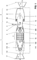
Fig. 1 zeigt, wie aus der Wellenachse 16 hervorgeht, eine Ringbrennkammer, welche im wesentlichen die Form eines zusammenhängenden annularen oder quasi-annularen Zylinders aufweist. Darüber hinaus kann eine solche Brennkammer auch aus einer Anzahl axial, quasi-axial oder schraubenförmig angeordneter und einzeln in sich abgeschlossener Brennräume bestehen. An sich kann die Brennkammer auch aus einem einzigen Rohr bestehen. Die Ringbrennkammer gemäss Fig. 1 besteht aus einer ersten 1 und einer zweiten Stufe 2, welche nacheinander geschaltet sind, und wobei die zweite Stufe 2 aus der eigentlichen Verbrennungszone 11 besteht. Die erste Stufe 1 besteht in Strömungsrichtung zunächst aus einer Anzahl von in Umfangsrichtung angeordneten Mischern 100, wobei der Mischer selbst im wesentlichen aus dem Brenner gemäss EP-0 321 809 abgeleitet ist. Was die folgende Beschreibung der Brennkammer betrifft, wird allein auf die eine Schnittebene gemäss Fig. 1 abgestellt. Selbstverständlich sind alle Komponenten der Brennkammer in entsprechender Anzahl in Umfangsrichtung angeordnet. Stromauf dieses Mischers 100 wirkt ein Kompressor 18, in welchem die angesaugte Luft 17 komprimiert wird. Die dann vom Kompressor gelieferte Luft 115 weist einen Druck von 10-40 bar bei einer Temperatur von 300-600°C auf. Diese Luft 115 strömt in den Mischer 100, dessen Betreibungsweise unter den Fig. 2-5 näher beschrieben wird. Nach einem kurzen Uebergangsstück 122 stromab des Mischers 100 erreicht das im Mischer 100 bereitgestellte Brennstoff/Luft-Gemisch 19 einen Katalysator 3, in welchem dieses Gemisch 19 vollständig verbrannt wird. Dabei ist das Gemisch 19 so gewählt, dass typische adiabate Flammentemperaturen zwischen 800 und 1050°C erreicht werden, womit die thermische Zerstörung des Katalysators 3 ausgeschlossen ist. Aufgrund der relativ niedrigen Temperatur findet keine homogene Gasphasenreaktion, sondern nur eine Reaktion an den aktiven Oberflächen des Katalysators 3 statt. Die NOx-Produktion einer solchen chemischen Umsetzung ist sehr niedrig, sehr viel kleiner als 1 ppmv. Am Ende des Katalysators 3 steht somit ein weitgehend NOx-freies Heissgas 4 zur Verfügung. Der Katalysator 3 selbst besteht aus einer ersten sehr aktiven Stufe, welche die Brennstoffumsetzung einleitet. Als Material wird hier vorzugsweise ein Palladiumoxid eingesetzt. Die nächsten Stufen des Katalysators 3 können aus anderen Materialien bestehen, beispielsweise aus Platin. Sonach wird im Katalysator 3 der Brennstoff weitgehend umgesetzt, wobei die Strömungsgeschwindigkeit im Katalysator 3 kleiner als ca. 30 m/s ist. Nach dem Austritt aus dem Katalysator 3 strömen die Heissgase 4 in eine Zuströmzone 5 und werden auf ca. 80-120 m/s beschleunigt. Die Zuströmzone 5 ist innenseitig und in Umfangsrichtung der Kanalwand 6 mit einer Reihe von wirbelerzeugenden Elementen 200, im folgenden nur noch Wirbel-Generatoren genannt, bestückt, auf welche weiter unten noch näher eingegangen wird. Die Heissgase 4 werden durch die Wirbel-Generatoren 200 derart verdrallt, dass in der anschliessenden Vormischstrecke 7 keine Rezirkulationsgebiete mehr im Nachlauf der genannten Wirbel-Generatoren 200 auftreten. In Umfangsrichtung dieser als Venturikanal ausgebildete Vormischstrecke 7 sind mehrere Brennstofflanzen 8 disponiert, welche die Zuführung eines Brennstoffes 9 und einer Stützluft 10 übernehmen. Die Zuführung dieser Medien zu den einzelnen Brennstofflanzen 8 kann bespielsweise über eine nicht gezeigte Ringleitung vorgenommen werden. Die von den Wirbel-Generatoren 200 ausgelöste Drallströmung sorgt für eine grossräumige Verteilung des eingebrachten Brennstoffes 9, allenfalls auch der zugemischten Stützluft 10. Des weiteren sorgt die Drallströmung für eine Homogenisierung des Gemisches aus Verbrennungsluft und Brennstoff. Der durch die Brennstofflanze 8 in die Heissgase 4 eingedüste Brennstoff 9 löst eine Selbstzündung aus, soweit diese Heissgase 4 jene spezifische Temperatur aufweisen, welche die brennstoffabhängige Selbstzündung auszulösen vermag. Wird die Ringbrennkammer mit einem gasförmigen Brennstoff betrieben, muss für die Inizierung einer Selbstzündung eine Temperatur der Heissgase 4 grösser 800°C vorliegen, die hier auch vorhanden ist. Bei einer solchen Verbrennung besteht, wie bereits oben gewürdigt, an sich die Gefahr eines Flammenrückschlages. Dieses Problem wird behoben, indem einerseits die Vormischzone 7 als Venturikanal ausgebildet wird, andererseits indem die Eindüsung des Brennstoffes 9 im Bereich der grössten Einschnürung in der Vormischzone 7 disponiert wird. Durch die Verengung in der Vormischzone 7 wird die Turbulenz durch die Anhebung der Axialgeschwindigkeit vermindert, was die Rückschlaggefahr durch die Verminderung der turbulenten Flammengeschwindigkeit minimiert wird. Andererseits wird die grossräumige Verteilung des Brennstoffes 9 weiterhin gewährleistet, da die Umfangskomponente der von den Wirbel-Generatoren 200 stammenden Drallströmung nicht beeinträchtigt wird. Hinter der relativ kurz gehaltenen Vormischzone 7 schliesst sich die Verbrennungszone 11 an. Der Uebergang zwischen der beiden Zonen wird durch einen radialen Querschnittssprung 12 gebildet, der zunächst den Durchflussquerschnitt der Verbrennungszone 11 indiziert. In der Ebene des Querschnittssprunges 12 stellt sich auch eine Flammenfront 21 ein. Um eine Rückzündung der Flamme ins Innere der Vormischzone 7 zu vermeiden muss die Flammenfront 21 stabil gehalten werden. Zu diesem Zweck werden die Wirbel-Generatoren 200 so ausgelegt, dass in der Vormischzone 7 noch keine Rezirkulation stattfindet; erst nach der plötzlichen Querschnittserweiterung findet das Aufplatzen der Drallströmung statt. Die Drallströmung unterstützt das schnelle Wiederanlegen der Strömung hinter dem Querschnittssprung 12, so dass durch die möglichst vollständige Ausnutzung des Volumens der Verbrennungszone 11 ein hoher Ausbrand bei kurzer Baulänge erzielt werden kann. Innerhalb dieses Querschnittssprunges 12 bildet sich während des Betriebes eine strömungsmässige Randzone, in welcher durch den dort vorherrschenden Unterdruck Wirbelablösungen entstehen, welche dann zu einer Stabilisierung der Flammenfront führen. Diese Eckwirbel 20 bilden auch die Zündzonen innerhalb der zweiten Stufe 2. Die in der Verbrennungszone 11 bereitgestellten heissen Arbeitsgase 13 beaufschlagen anschliessend eine stromab wirkende Turbine 14. Die Abgase 15 können anschliessend zum Betrieb eines Dampfkreislaufes herangezogen werden, wobei im letztgenannten Fall die Schaltung dann eine Kombianlage ist.1 shows, as can be seen from the
Zusammenfassend lässt sich sagen, dass aufgrund der hohen Strömungsgeschwindigkeit ein Einsetzen der Nachverbrennung im Strömungskanal ausgeschlossen ist. Bei Verbrennung von Oel kann durch Wasserzugabe eine unmittelbare Zündung verhindert werden. Zur Stabilisierung der Nachverbrennung dient, wie bereits erläutert, der Querschnittssprung 12. In den Eckwirbeln 20 erfolgt aufgrund der langen Aufenthaltszeit die Selbstzündung des Gemisches. Die Flammenfront 21 schreitet zur Mitte der Verbrennungszone 11 hin fort. Kurz stromab des Vereinigungspunktes beider Flammenfrontpartien ist auch der CO-Ausbrand abgeschlossen. Typische Verbrennungstemperaturen sind 1300-1600°C. Das Verfahren, Brennstoff in ein Heissgas einzudüsen, ist prädestiniert, nur wenig NOx zu produzieren.In summary, it can be said that due to the high flow rate, the onset of post-combustion in the flow channel is impossible. When burning oil an immediate ignition can be prevented by adding water. As already explained, the
Das vorgeschlagene Verfahren besitzt auch ein sehr gutes Verhalten hinsichtlich eines breiten Lastbereiches. Da die Mischung in der ersten Stufe 1 immer weitgehend konstant gehalten wird, können auch die UHC- oder CO-Emissionen verhindert werden. Die konstante Temperatur am Eintritt in die zweite Stufe 2 stellt eine sichere Selbstzündung des Gemisches sicher, unabhängig von der Brennstoffmenge in der zweiten Stufe 2. Die Eintrittstemperatur ist weiterhin hoch genug, um einen ausreichenden Ausbrand in der zweiten Stufe 2 auch bei geringer Brennstoffmenge zu erreichen. Die Leistungsregelung über die Gasturbinenlast erfolgt im wesentlichen durch die Anpassung der Brennstoffmenge in der zweiten Stufe 2. Der regelbare Kompressor 18 stellt sicher, dass bei Nullast die oben beschriebene Mindestverbrennungstemperatur am Austritt des Katalysators 3 nicht unterschritten wird.The proposed method also behaves very well with regard to a wide load range. Since the mixture in the first stage 1 is always kept largely constant, the UHC or CO emissions can also be prevented. The constant temperature at the entrance to the
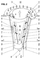
Um den Aufbau des Mischers 100 besser zu verstehen, ist es von Vorteil, wenn gleichzeitig zu Fig. 2 die einzelnen Schnitte nach den Figuren 3-5 herangezogen werden. Des weiteren, um Fig. 2 nicht unnötig unübersichtlich zu gestalten, sind in ihr die nach den Figuren 3-5 schematisch gezeigten Leitbleche 121a, 121b nur andeutungsweise aufgenommen worden. Im folgenden wird bei der Beschreibung von Fig. 2 nach Bedarf auf die restlichen Figuren 3-5 hingewiesen.In order to better understand the structure of the
Der Mischer 100 nach Fig. 2 besteht aus zwei hohlen kegelförmigen Teilkörpern 101, 102, die versetzt zueinander ineinandergeschachtelt sind. Die Versetzung der jeweiligen Mittelachse oder Längssymmetrieachse 201b, 202b der kegeligen Teilkörper 101, 102 zueinander schafft auf beiden Seiten, in spiegelbildlicher Anordnung, jeweils einen tangentialen Lufteintrittsschlitz 119, 120 frei (Fig. 3-5), durch welche die Verbrennungsluft 115 in Innenraum des Mischers 100, d.h. in den Kegelhohlraum 114 strömt. Die Kegelform der gezeigten Teilkörper 101, 102 in Strömungsrichtung weist einen bestimmten festen Winkel auf. Selbstverständlich, je nach Betriebseinsatz, können die Teilkörper 101, 102 in Strömungsrichtung eine zunehmende oder abnehmende Kegelneigung aufweisen, ähnlich einer Trompete resp. Tulpe. Die beiden letztgenannten Formen sind zeichnerisch nicht erfasst, da sie für den Fachmann ohne weiteres nachempfindbar sind. Die beiden kegeligen Teilkörper 101, 102 weisen je einen zylindrischen Anfangsteil 101a, 102a, die ebenfalls, analog den kegeligen Teilkörpern 101, 102, versetzt zueinander verlaufen, so dass die tangentialen Lufteintrittsschlitze 119, 120 über die ganze Länge des Mischers 100 vorhanden sind. Im Bereich des zylindrischen Anfangsteils ist eine Düse 103 untergebracht, deren Eindüsung 104 in etwa mit dem engsten Querschnitt des durch die kegeligen Teilkörper 101, 102 gebildeten Kegelhohlraum 114 zusammenfällt. Die Eindüsungskapazität und die Art dieser Düse 103 richtet sich nach den vorgegebenen Parametern des jeweiligen Mischers 100. Selbstverständlich kann der Mischer 100 rein kegelig, also ohne zylindrische Anfangsteile 101a, 102a, ausgeführt sein. Die kegeligen Teilkörper 101, 102 weisen des weiteren je eine Brennstoffleitung 108, 109 auf, welche entlang der tangentialen Eintrittsschlitze 119, 120 angeordnet und mit Eindüsungsöffnungen 117 versehen sind, durch welche vorzugsweise ein gasförmiger Brennstoff 113 in die dort durchströmende Verbrennungsluft 115 eingedüst wird, wie dies die Pfeile 116 versinnbildlichen wollen. Diese Brennstoffleitungen 108, 109 sind vorzugsweise spätestens am Ende der tangentialen Einströmung, vor Eintritt in den Kegelhohlraum 114, plaziert, dies um eine optimale Luft/Brennstoff-Mischung zu erhalten. Im Bereich des Uebergangsstückes 122 geht die Ausgangsöffnung des Mischers 100 in eine Frontwand 110 über, in welcher eine Anzahl Bohrungen 110a vorhanden sind. Die letztgenannten treten bei Bedarf in Funktion, und sorgen dafür, dass Verdünnungsluft oder Kühlluft 110b dem vorderen Teil des Uebergangsstückes 122 zugeführt wird. Bei dem durch die Düse 103 herangeführten Brennstoff handelt es sich um einen flüssigen Brennstoff 112, der allenfalls mit einem rückgeführten Abgas angereichert sein kann. Dieser Brennstoff 112 wird unter einem spitzen Winkel in den Kegelhohlraum 114 eingedüst. Aus der Düse 103 bildet sich sonach ein kegeliges Brennstoffprofil 105, das von der tangential einströmenden rotierenden Verbrennungsluft 115 umschlossen wird. In axialer Richtung wird die Konzentration des Brennstoffes 112 fortlaufend durch die einströmenden Verbrennungsluft 115 zu einer optimalen Gemisch abgebaut. Wird der Mischer 100 mit einem gasförmigen Brennstoff 113 betrieben, so geschieht dies vorzugsweise über Oeffnungsdüsen 117, wobei die Bildung dieses Brennstoff/Luft-Gemisches direkt am Ende der Lufteintrittsschlitze 119, 120 zustande kommt. Bei der Eindüsung des Brennstoffes 112 über die Brennstoffdüse 103 wird am Ende des Mischers 100 die optimale, homogene Brennstoffkonzentration über den Querschnitt erreicht. Ist die Verbrennungsluft 115 zusätzlich vorgeheizt oder mit einem rückgeführten Abgas angereichert, so unterstützt dies die Verdampfung des flüssigen Brennstoffes 112 nachhaltig. Die gleichen Ueberlegungen gelten auch, wenn über die Leitungen 108, 109 statt gasförmige flüssige Brennstoffe zugeführt werden. Bei der Gestaltung der kegeligen Teilkörper 101, 102 hinsichtlich Kegelwinkel und Breite der tangentialen Lufteintrittsschlitze 119, 120 sind an sich enge Grenzen einzuhalten, damit sich das gewünschte Strömungsfeld der Verbrennungsluft 115 am Ausgang des Mischers 100 einstellen kann. Allgemein ist zu sagen, dass eine Minimierung des Querschnittes der tangentialen Lufteintrittsschlitze 119, 120 prädestiniert ist, eine Rückströmzone 106 zu bilden. In unserem Fall soll aber gerade keine Rückströmzone gebildet werden, weshalb die Aerodynamik des Mischers 100 so sein muss, dass der Drall wesentlich zu reduzieren ist. Dies geschieht durch 20-100% breitere Lufteintrittsschlitze 119, 120 gegenüber einen gleichem Körper, der als Vormischbrenner dient. Eine andere Möglichkeit, die Bildung einer Rückströmzone zu verhindern, besteht darin, die Anzahl der Lufteintrittschlitze zu vergrössern, wobei zugleich auch die Zahl der Teilkörper entsprechend zunimmt. Die Axialgeschwindigkeit innerhalb des Mischers 100 lässt sich durch eine entsprechende nicht gezeigte Zuführung eines axialen Verbrennungsluftstromes verändern. Die Konstruktion des Mischers 100 eignet sich des weiteren vorzüglich, die Grösse der tangentialen Lufteintrittsschlitze 119, 120 zu verändern, womit ohne Veränderung der Baulänge des Mischers 100 eine relativ grosse betriebliche Bandbreite erfasst werden kann. Selbstverständlich sind die Teilkörper 101, 102 auch in einer anderen Ebene zueinander verschiebbar, wodurch sogar eine Ueberlappung derselben angesteuert werden kann. Es ist sogar möglich, die Teilkörper 101, 102 durch eine gegenläufige drehende Bewegung spiralartig ineinander zu verschachteln.The
Aus Fig. 3-5 geht nunmehr die geometrische Konfiguration der Leitbleche 121a, 121b hervor. Sie haben Strömungseinleitungsfunktion, wobei diese, entsprechend ihrer Länge, das jeweilige Ende der kegeligen Teilkörper 101, 102 in Anströmungsrichtung gegenüber der Verbrennungsluft 115 verlängern. Die Kanalisierung der Verbrennungsluft 115 in den Kegelhohlraum 114 kann durch Oeffnen bzw. Schliessen der Leitbleche 121a, 121b um einen im Bereich des Eintritts dieses Kanals in den Kegelhohlraum 114 plazierten Drehpunkt 123 optimiert werden, insbesondere ist dies vonnöten, wenn die ursprüngliche Spaltgrösse der tangentialen Lufteintrittsschlitze 119, 120 aus oben genannten Motiven zu verändern ist. Selbstverständlich können diese dynamische Vorkehrungen auch statisch vorgesehen werden, indem bedarfsmässige Leitbleche einen festen Bestandteil mit den kegeligen Teilkörpern 101, 102 bilden. Ebenfalls kann der Mischer 100 auch ohne Leitbleche betrieben werden, oder es können andere Hilfsmittel hierfür vogesehen werden.3-5 now shows the geometrical configuration of the
In den Figuren 6, 7 und 8 ist die eigentliche Zuströmzone 5 nicht dargestellt. Dargestellt ist hingegen durch einen Pfeil die Strömung der Heissgase 4, womit auch die Strömungsrichtung vorgegeben ist. Gemäss diesen Figuren besteht ein Wirbel-Generator 200, 201, 202 im wesentlichen aus drei frei umströmten dreieckigen Flächen. Es sind dies eine Dachfläche 210 und zwei Seitenflächen 211 und 213. In ihrer Längserstreckung verlaufen diese Flächen unter bestimmten Winkeln in Strömungsrichtung. Die Seitenwände der Wirbel-Generatoren 200, 201, 202, welche vorzugsweise aus rechtwinkligen Dreiecken bestehen, sind mit ihren Längsseiten auf der bereits angesprochenen Kanalwand 6 fixiert, vorzugsweise gasdicht. Sie sind so orientiert, dass sie an ihren Schmalseiten einen Stoss bilden unter Einschluss eines Pfeilwinkels α. Der Stoss ist als scharfe Verbindungskante 216 ausgeführt und steht senkrecht zu jeder Kanalwand 6, mit welcher die Seitenflächen bündig sind. Die beiden den Pfeilwinkel α einschliessenden Seitenflächen 211, 213 sind in Fig. 4 symmetrisch in Form, Grösse und Orientierung, sie sind beidseitig einer Symmetrieachse 217 angeordnet, welche gleichgerichtet wie die Kanalachse ist.
Die Dachfläche 210 liegt mit einer quer zum durchströmten Kanal verlaufenden und sehr schmal ausgebildeten Kante 215 an der gleichen Kanalwand 6 an wie die Seitenflächen 211, 213. Ihre längsgerichteten Kanten 212, 214 sind bündig mit den in den Strömungskanal hineinragenden, längsgerichteten Kanten der Seitenflächen 211, 213. Die Dachfläche 210 verläuft unter einem Anstellwinkel Θ zur Kanalwand 6, deren Längskanten 212, 214 bilden zusammen mit der Verbindungskante 216 eine Spitze 218. Selbstverständlich kann der Wirbel-Generator 200, 201, 202 auch mit einer Bodenfläche versehen sein, mit welcher er auf geeignete Weise an der Kanalwand 6 befestigt ist. Eine derartige Bodenfläche steht indessen in keinem Zusammenhang mit der Wirkungsweise des Elementes.The
The
Die Wirkungsweise des Wirbel-Generators 200, 201, 202 ist die folgende: Beim Umströmen der Kanten 212 und 214 wird die Hauptströmung in ein Paar gegenläufiger Wirbel umgewandelt, wie dies in den Figuren schematisch skizziert ist. Die Wirbelachsen liegen in der Achse der Hauptströmung. Die Drallzahl und der Ort des Wirbelaufplatzens (Vortex Breakdown), sofern letzteres angestrebt wird, werden durch entsprechende Wahl des Anstellwinkels Θ und des Pfeilwinkels α bestimmt. Mit steigenden Winkeln wird die Wirbelstärke bzw. die Drallzahl erhöht, und der Ort des Wirbelaufplatzens verschiebt sich stromaufwärts bis hin in den Bereich des Wirbel-Generators 200, 201, 202 selbst. Je nach Anwendung sind diese beiden Winkel Θ und α durch konstruktive Gegebenheiten und durch den Prozess selbst vorgegeben. Angepasst werden müssen diese Wirbel-Generatoren nur noch bezüglich Länge und Höhe, wie dies weiter unten unter Fig. 9 noch detailliert zur Ausführung gelangen wird.The mode of operation of the
In Fig. 6 bildet die Verbindungskante 216 der beiden Seitenflächen 211, 213 die stromabwärtsseitige Kante des Wirbel-Generators 200. Die quer zum durchströmten Kanal verlaufende Kante 215 der Dachfläche 210 ist somit die von der Kanalströmung zuerst beaufschlagte Kante.In FIG. 6, the connecting
In Fig. 7 ist ein sogenannter halber "Wirbel-Generator" auf der Basis eines Wirbel-Generators nach Fig. 6 gezeigt. Beim hier gezeigten Wirbel-Generator 201 ist nur die eine der beiden Seitenflächen mit dem Pfeilwinkel α/2 versehen. Die andere Seitenfläche ist gerade und in Strömungsrichtung ausgerichtet. Im Gegensatz zum symmetrischen Wirbel-Generator wird hier nur ein Wirbel an der gepfeilten Seite erzeugt, wie dies in der Figur versinnbildlicht wird. Demnach liegt stromab dieses Wirbel-Generators kein wirbelneutrales Feld vor, sondern der Strömung wird ein Drall aufgezwungen.FIG. 7 shows a so-called half "vortex generator" based on a vortex generator according to FIG. 6. In the
Fig. 8 unterscheidet sich gegenüber Fig. 6 insoweit, als hier die scharfe Verbindungskante 216 des Wirbel-Generators 202 jene Stelle ist, welche von der Kanalströmung zuerst beaufschlagt wird. Das Element ist demnach um 180° gedreht. Wie aus der Darstellung ersichtlich ist, haben die beiden gegenläufigen Wirbel ihren Drehsinn geändert.FIG. 8 differs from FIG. 6 in that the sharp connecting
Fig. 9 zeigt die grundsätzliche Geometrie eines in einem Kanal 5 eingebauten Wirbel-Generators 200. In der Regel wird man die Höhe h der Verbindungskante 216 mit der Kanalhöhe H, oder der Höhe des Kanalteils, welchem dem Wirbel-Generator zugeordnet ist, so abstimmen, dass der erzeugte Wirbel unmittelbar stromab des Wirbel-Generators 200 bereits eine solche Grösse erreicht, dergestalt, dass damit die volle Kanalhöhe H ausgefüllt wird. Dies führt zu einer gleichmässigen Geschwindigkeitsverteilung in dem beaufschlagten Querschnitt. Ein weiteres Kriterium, das Einfluss auf das zu wählende Verhältnis der beiden Höhen h/H nehmen kann, ist der Druckabfall, der beim Umströmen des Wirbel-Generators 200 auftritt. Es versteht sich, dass mit grösserem Verhältnis h/H auch der Druckverlustbeiwert ansteigt.9 shows the basic geometry of a
Die Wirbel-Generatoren 200, 201, 202 werden hauptsächlich dort eingesetzt, wo es darum geht, zwei Strömungen miteinander zu mischen. Die Hauptströmung 4 als Heissgase attackiert in Pfeilrichtung die quergerichtete Kante 215, respektiv die Verbindungskante 216. Die Sekundärströmung in Form eines gasförmigen und/oder flüssigen Brennstoffes, der allenfalls mit einem Anteil Stützluft angereichert ist (Vgl. Fig. 1), weist einen wesentlichen kleineren Massenstrom als die Hauptströmung auf. Diese Sekündärströmung wird im vorliegenden Fall stromab des Wirbel-Generators in die Hauptströmung eingeleitet, wie dies aus Fig. 1 besonders gut hervorgeht.The
Im dargestellten Beispiel gemäss Fig. 1 sind vier Wirbel-Generatoren 200 mit Abstand über den Umfang des Kanals 5 verteilt. Selbstverständlich können die Wirbel-Generatoren in Umfangsrichtung auch so aneinander gereiht werden, dass keine Zwischenräume an der Kanalwand 6 freigelassen werden. Für die Wahl der Anzahl und der Anordnung der Wirbel-Generatoren ist letzlich der zu erzeugenden Wirbel entscheidend.In the example shown in FIG. 1, four
Die Figuren 10-16 zeigen weitere mögliche Formen der Einführung des Brennstoffes in die Heissgase 4. Diese Varianten können auf vielfältige Weise miteinander und mit einer zentralen Brennstoffeindüsung, wie sie beispielsweise aus Fig. 1 hervorgeht, kombiniert werden.FIGS. 10-16 show further possible forms of introducing the fuel into the
In Fig. 10 wird der Brennstoff, zusätzlich zu Kanalwandbohrungen 220, die sich stromabwärts der Wirbel-Generatoren befinden, auch über Wandbohrungen 221 eingedüst, die sich unmittelbar neben der Seitenflächen 211, 213 und in deren Längserstreckung in der gleichen Kanalwand 6 befinden, an der die Wirbel-Generatoren angeordnet sind. Die Einleitung des Brennstoffes durch die Wandbohrungen 221 verleiht den erzeugten Wirbeln einen zusätzlichen Impuls, was die Lebensdauer des Wirbel-Generators verlängert.In Fig. 10, in addition to channel wall bores 220, which are located downstream of the vortex generators, the fuel is also injected via wall bores 221, which are located directly next to the side surfaces 211, 213 and in their longitudinal extent in the
In Fig. 11 und 12 wird der Brennstoff über einen Schlitz 222 oder über Wandbohrungen 223 eingedüst, wobei sich beide Vorkehrungen unmittelbar vor der quer zum durchströmten Kanal verlaufenden Kante 215 der Dachfläche 210 und in deren Längserstreckung in der gleichen Kanalwand 6 befinden, an der die Wirbel-Generatoren angeordnet sind. Die Geometrie der Wandbohrungen 223 oder des Schlitzes 222 ist so gewählt, dass der Brennstoff unter einem bestimmten Eindüsungswinkel in die Hauptströmung 4 eingegeben wird und den nachplazierten Wirbel-Generator als Schutzfilm gegen die heisse Hauptströmung 4 durch Umströmung weitgehend abschirmt.11 and 12, the fuel is injected via a
In den nachstehend beschriebenen Beispielen wird die Sekundärströmung (Vgl. oben) zunächst über nicht gezeigte Führungen durch die Kanalwand 6 ins hohle Innere der Wirbel-Generatoren eingeleitet. Damit wird, ohne weitere Dispositiven vorzusehen, eine interne Kühlmöglichkeit für die Wirbel-Generatoren geschaffen.In the examples described below, the secondary flow (cf. above) is first introduced into the hollow interior of the vortex generators via guides (not shown) through the
In Fig. 13 wird der Brennstoff über Wandbohrungen 224 eingedüst, welche sich innerhalb der Dachfläche 210 unmittelbar hinter und entlang der quer zum durchströmten Kanal verlaufenden Kante 215. Die Kühlung des Wirbel-Generators erfolgt hier mehr extern als intern. Die austretende Sekundärströmung bildet beim Umströmen der Dachfläche 210 eine diese gegen die heisse Hauptströmung 4 abschirmende Schutzschicht.13, the fuel is injected via wall bores 224, which are located inside the
In Fig. 14 wird der Brennstoff über Wandbohrungen 225 eingedüst, welche innerhalb der Dachfläche 210 entlang der Symmetrielinie 217 gestaffelt angeordnet sind. Mit dieser Variante werden die Kanalwände 6 besonders gut vor der heissen Hauptströmung 4 geschützt, da der Brennstoff zunächst am Aussenumfang der Wirbel eingeführt wird.In FIG. 14, the fuel is injected via wall bores 225, which are staggered within the
In Fig. 15 wird der Brennstoff über Wandbohrungen 226 eingedüst, die sich in den längsgerichteten Kanten 212, 214 der Dachfläche 210 befinden. Diese Lösung gewährleistet eine gute Kühlung der Wirbel-Generatoren, da der Brennstoff an dessen Extremitäten austritt und somit die Innenwandungen des Elementes voll umspült. Die Sekundärströmung wird hier direkt in den entstehenden Wirbel hineingegeben, was zu definierten Strömungsverhältnissen führt.15, the fuel is injected via wall bores 226, which are located in the
In Fig. 16 geschieht die Eindüsung über Wandbohrungen 227, die sich in den Seitenflächen 211 und 213 befinden, einerseits im Bereich der Längskanten 212 und 214, andererseits im Bereich der Verbindungskante 216. Diese Variante ist wirkungsähnlich wie jene aus Fig. 10 (Bohrungen 221) und aus Fig. 15 (Bohrungen 226).16, the injection takes place via wall bores 227, which are located in the side surfaces 211 and 213, on the one hand in the area of the
- 11
- Erste StufeFirst stage
- 22nd
- Zweite StufeSecond step
- 33rd
- Katalysatorcatalyst
- 44th
- Heissgase, HauptströmungHot gases, main flow
- 55
- Zuströmzone, Kanal der ZuströmzoneInflow zone, channel of the inflow zone
- 66
- Kanalwand der ZuströmzoneCanal wall of the inflow zone
- 77
- VormischzonePremixing zone
- 88th
- BrennstofflanzeFuel lance
- 99
- Brennstofffuel
- 1010th
- StützluftSupport air
- 1111
- VerbrennungszoneCombustion zone
- 1212th
- QuerschnittssprungCross-sectional jump
- 1313
- Heisse ArbeitsgaseHot working gases
- 1414
- Turbineturbine
- 1515
- AbgaseExhaust gases
- 1616
- WellenachseShaft axis
- 1717th
- AnsaugluftIntake air
- 1818th
- Kompressorcompressor
- 1919th
- Brennstoff/Luft-GemischAir / fuel mixture
- 2020th
- Eckenwirbel, ZündzonenCorner swirls, ignition zones
- 2121
- FlammenfrontFlame front
- 100100
- Mischermixer
- 101, 102101, 102
- TeilkörperPartial body
- 101a, 102a101a, 102a
- Zylindrische AnfangsteileCylindrical starting parts
- 101b, 102b101b, 102b
- LängssymmetrieachsenLongitudinal symmetry axes
- 103103
- BrennstoffdüseFuel nozzle
- 104104
- BrennstoffeindüsungFuel injection
- 105105
- BrennstoffeindüsungsprofilFuel injection profile
- 108, 109108, 109
- BrennstoffleitungenFuel lines
- 110110
- FrontwandFront wall
- 110a110a
- LuftbohrungenAir holes
- 110b110b
- KühlluftCooling air
- 112112
- Flüssiger BrennstoffLiquid fuel
- 113113
- Gasförmiger BrennstoffGaseous fuel
- 114114
- KegelhohlraumCone cavity
- 115115
- VerbrennungsluftCombustion air
- 116116
- Brennstoff-EindüsungFuel injection
- 117117
- BrennstoffdüsenFuel nozzles
- 119, 120119, 120
- Tangentiale LufteintrittsschlitzeTangential air inlet slots
- 121a, 121b121a, 121b
- LeitblecheBaffles
- 122122
- UebergangsstückTransition piece
- 123123
- Drehpunkt der LeitblechePivot point of the guide plates
- 200, 201, 202200, 201, 202
- Wirbel-GeneratorenVortex generators
- 210210
- DachflächeRoof area
- 211, 213211, 213
- SeitenflächenSide faces
- 212, 214212, 214
- Längsgerichtete KantenLongitudinal edges
- 215215
- Querverlaufende KanteTransverse edge
- 216216
- VerbindungskanteConnecting edge
- 217217
- SymmetrieachseAxis of symmetry
- 218218
- Spitzetop
- 220-227220-227
- Bohrungen zur Eindüsung eines BrennstoffesDrilling holes for fuel injection
- L, h,L, h,
- Abmessungen des Wirbel-GeneratorsDimensions of the vortex generator
- HH
- Höhe des KanalsHeight of the channel
- αα
- PfeilwinkelArrow angle
- ΘΘ
- AnstellwinkelAngle of attack
Claims (13)
Applications Claiming Priority (2)
| Application Number | Priority Date | Filing Date | Title |
|---|---|---|---|
| DE4426351 | 1994-07-25 | ||
| DE4426351A DE4426351B4 (en) | 1994-07-25 | 1994-07-25 | Combustion chamber for a gas turbine |
Publications (1)
| Publication Number | Publication Date |
|---|---|
| EP0694740A2 true EP0694740A2 (en) | 1996-01-31 |
Family
ID=6524114
Family Applications (1)
| Application Number | Title | Priority Date | Filing Date |
|---|---|---|---|
| EP95810442A Withdrawn EP0694740A2 (en) | 1994-07-25 | 1995-07-05 | Combustion chamber |
Country Status (5)
| Country | Link |
|---|---|
| US (1) | US5626017A (en) |
| EP (1) | EP0694740A2 (en) |
| JP (1) | JPH08189641A (en) |
| CN (1) | CN1121570A (en) |
| DE (1) | DE4426351B4 (en) |
Cited By (21)
| Publication number | Priority date | Publication date | Assignee | Title |
|---|---|---|---|---|
| EP0745809A1 (en) * | 1995-06-02 | 1996-12-04 | ABB Management AG | Vortex generator for combustion chamber |
| EP0718561B1 (en) * | 1994-12-24 | 2001-03-14 | ABB (Schweiz) AG | Combustor |
| EP1255080A1 (en) * | 2001-04-30 | 2002-11-06 | ALSTOM (Switzerland) Ltd | Catalytic burner |
| EP1279898A3 (en) * | 2001-07-26 | 2003-04-16 | ALSTOM (Switzerland) Ltd | Premix burner with high flame stability |
| WO2005095855A1 (en) * | 2004-03-30 | 2005-10-13 | Alstom Technology Ltd | Device and method for stabilizing the flame in a burner |
| US7069727B2 (en) | 2003-02-11 | 2006-07-04 | Alstom Technology Ltd. | Method for operating a gas turbo group |
| EP2071155A2 (en) * | 2007-12-14 | 2009-06-17 | United Technologies Corporation | Nacelle assembly with turbulators |
| WO2009109454A1 (en) * | 2008-03-07 | 2009-09-11 | Alstom Technology Ltd | Method and burner arrangement for the production of hot gas, and use of said method |
| WO2009109448A1 (en) * | 2008-03-07 | 2009-09-11 | Alstom Technology Ltd | Burner arrangement, and use of such a burner arrangement |
| US8057224B2 (en) * | 2004-12-23 | 2011-11-15 | Alstom Technology Ltd. | Premix burner with mixing section |
| US8192147B2 (en) | 2007-12-14 | 2012-06-05 | United Technologies Corporation | Nacelle assembly having inlet bleed |
| US8282037B2 (en) | 2007-11-13 | 2012-10-09 | United Technologies Corporation | Nacelle flow assembly |
| US8468833B2 (en) | 2008-03-07 | 2013-06-25 | Alstom Technology Ltd | Burner arrangement, and use of such a burner arrangement |
| WO2013139914A1 (en) * | 2012-03-23 | 2013-09-26 | Alstom Technology Ltd | Combustion device |
| EP2700878A3 (en) * | 2012-08-24 | 2014-03-26 | Alstom Technology Ltd | Method for mixing a dilution air in a sequential combustion system of a gas turbine |
| WO2014063835A1 (en) * | 2012-10-24 | 2014-05-01 | Alstom Technology Ltd | Sequential combustion with dilution gas mixer |
| CN105371301A (en) * | 2015-10-08 | 2016-03-02 | 北京航空航天大学 | Staged combustor of high-temperature jet flow ignition self-stabilization flame |
| AU2012320439B2 (en) * | 2011-10-07 | 2016-05-19 | Wobben Properties Gmbh | Method and device for mounting a rotor of a wind energy plant |
| EP3267107A1 (en) * | 2016-07-08 | 2018-01-10 | Ansaldo Energia IP UK Limited | Method of controlling a gas turbine assembly |
| EP3889506A1 (en) * | 2020-03-31 | 2021-10-06 | Siemens Aktiengesellschaft | Burner component of a burner and burner of a gas turbine with same |
| WO2021197654A1 (en) * | 2020-03-31 | 2021-10-07 | Siemens Aktiengesellschaft | Burner component of a burner, and burner of a gas turbine having a burner component of this type |
Families Citing this family (86)
| Publication number | Priority date | Publication date | Assignee | Title |
|---|---|---|---|---|
| DE19614001A1 (en) * | 1996-04-09 | 1997-10-16 | Abb Research Ltd | Combustion chamber |
| DE19649486A1 (en) * | 1996-11-29 | 1998-06-04 | Abb Research Ltd | Combustion chamber |
| US6000930A (en) * | 1997-05-12 | 1999-12-14 | Altex Technologies Corporation | Combustion process and burner apparatus for controlling NOx emissions |
| US6155819A (en) * | 1998-06-12 | 2000-12-05 | Precision Combustion, Inc. | Dry, low NOx catalytic pilot |
| WO2000019081A2 (en) * | 1998-08-17 | 2000-04-06 | Ramgen Power Systems, Inc. | Fuel supply and fuel - air mixing for a ram jet combustor |
| US6339925B1 (en) * | 1998-11-02 | 2002-01-22 | General Electric Company | Hybrid catalytic combustor |
| DE19905996A1 (en) | 1999-02-15 | 2000-08-17 | Abb Alstom Power Ch Ag | Fuel lance for injecting liquid and / or gaseous fuels into a combustion chamber |
| DE19905995A1 (en) * | 1999-02-15 | 2000-08-17 | Asea Brown Boveri | Injection lance or nozzle for liquid and gaseous fuel in combustion chamber is part of secondary or tertiary burner around which flows hot gas jet in main flow direction |
| DE10056243A1 (en) * | 2000-11-14 | 2002-05-23 | Alstom Switzerland Ltd | Combustion chamber and method for operating this combustion chamber |
| US6652265B2 (en) | 2000-12-06 | 2003-11-25 | North American Manufacturing Company | Burner apparatus and method |
| DE10061527A1 (en) | 2000-12-11 | 2002-06-13 | Alstom Switzerland Ltd | Premix burner assembly with catalytic combustion and method of operation therefor |
| DE50212351D1 (en) * | 2001-04-30 | 2008-07-24 | Alstom Technology Ltd | Apparatus for burning a gaseous fuel-oxidizer mixture |
| US6564555B2 (en) | 2001-05-24 | 2003-05-20 | Allison Advanced Development Company | Apparatus for forming a combustion mixture in a gas turbine engine |
| US7603841B2 (en) * | 2001-07-23 | 2009-10-20 | Ramgen Power Systems, Llc | Vortex combustor for low NOx emissions when burning lean premixed high hydrogen content fuel |
| DE10164097A1 (en) * | 2001-12-24 | 2003-07-03 | Alstom Switzerland Ltd | Premixing burner comprises a twisting arrangement having tangential inlets for introducing a combustion air stream into the inner chamber of the twisting arrangement, and devices for introducing a fuel into the combustion air stream |
| JP2003306307A (en) * | 2002-04-09 | 2003-10-28 | Nissan Motor Co Ltd | Fuel-reforming apparatus |
| DE10330023A1 (en) * | 2002-07-20 | 2004-02-05 | Alstom (Switzerland) Ltd. | Vortex generator used in the swirling and mixing of fuel/air mixtures in pre-mixing combustion chambers comprises an outlet opening for targeted introduction of a secondary flow into the core flow of the wake produced |
| EP1439349A1 (en) | 2003-01-14 | 2004-07-21 | Alstom Technology Ltd | Combustion method and burner for carrying out the method |
| US7096671B2 (en) * | 2003-10-14 | 2006-08-29 | Siemens Westinghouse Power Corporation | Catalytic combustion system and method |
| US7421843B2 (en) * | 2005-01-15 | 2008-09-09 | Siemens Power Generation, Inc. | Catalytic combustor having fuel flow control responsive to measured combustion parameters |
| DE102005061486B4 (en) * | 2005-12-22 | 2018-07-12 | Ansaldo Energia Switzerland AG | Method for operating a combustion chamber of a gas turbine |
| US7797944B2 (en) | 2006-10-20 | 2010-09-21 | United Technologies Corporation | Gas turbine engine having slim-line nacelle |
| US7870721B2 (en) * | 2006-11-10 | 2011-01-18 | United Technologies Corporation | Gas turbine engine providing simulated boundary layer thickness increase |
| SE530775C2 (en) * | 2007-01-05 | 2008-09-09 | Zemission Ab | Heating device for catalytic combustion of liquid fuels and a stove comprising such a heating device |
| US8727267B2 (en) * | 2007-05-18 | 2014-05-20 | United Technologies Corporation | Variable contraction ratio nacelle assembly for a gas turbine engine |
| US8402739B2 (en) * | 2007-06-28 | 2013-03-26 | United Technologies Corporation | Variable shape inlet section for a nacelle assembly of a gas turbine engine |
| US9228534B2 (en) | 2007-07-02 | 2016-01-05 | United Technologies Corporation | Variable contour nacelle assembly for a gas turbine engine |
| US8671658B2 (en) | 2007-10-23 | 2014-03-18 | Ener-Core Power, Inc. | Oxidizing fuel |
| EP2058590B1 (en) * | 2007-11-09 | 2016-03-23 | Alstom Technology Ltd | Method for operating a burner |
| EP2220433B1 (en) * | 2007-11-27 | 2013-09-04 | Alstom Technology Ltd | Method and device for burning hydrogen in a premix burner |
| EP2072899B1 (en) | 2007-12-19 | 2016-03-30 | Alstom Technology Ltd | Fuel injection method |
| EP2116766B1 (en) * | 2008-05-09 | 2016-01-27 | Alstom Technology Ltd | Burner with fuel lance |
| CN102224378B (en) * | 2008-09-22 | 2014-07-23 | 达塞尔·卡尔灵顿 | Burner |
| US8701413B2 (en) | 2008-12-08 | 2014-04-22 | Ener-Core Power, Inc. | Oxidizing fuel in multiple operating modes |
| EP2253888B1 (en) * | 2009-05-14 | 2013-10-16 | Alstom Technology Ltd | Burner of a gas turbine having a vortex generator with fuel lance |
| US8408872B2 (en) * | 2009-09-24 | 2013-04-02 | General Electric Company | Fastback turbulator structure and turbine nozzle incorporating same |
| DE102010037688A1 (en) * | 2009-09-24 | 2011-03-31 | General Electric Co. | Fastback turbulator structure and a turbine nozzle containing same |
| WO2011054766A2 (en) | 2009-11-07 | 2011-05-12 | Alstom Technology Ltd | Reheat burner injection system |
| EP2496883B1 (en) | 2009-11-07 | 2016-08-10 | Alstom Technology Ltd | Premixed burner for a gas turbine combustor |
| EP2496880B1 (en) | 2009-11-07 | 2018-12-05 | Ansaldo Energia Switzerland AG | Reheat burner injection system |
| EP2496885B1 (en) | 2009-11-07 | 2019-05-29 | Ansaldo Energia Switzerland AG | Burner with a cooling system allowing an increased gas turbine efficiency |
| WO2011054757A2 (en) | 2009-11-07 | 2011-05-12 | Alstom Technology Ltd | Reheat burner injection system with fuel lances |
| JP2011102669A (en) * | 2009-11-10 | 2011-05-26 | Mitsubishi Heavy Ind Ltd | Gas turbine combustor and gas turbine |
| EP2420731B1 (en) | 2010-08-16 | 2014-03-05 | Alstom Technology Ltd | Reheat burner |
| CH704829A2 (en) * | 2011-04-08 | 2012-11-15 | Alstom Technology Ltd | Gas turbine group and associated operating method. |
| RU2550370C2 (en) | 2011-05-11 | 2015-05-10 | Альстом Текнолоджи Лтд | Centrifugal nozzle with projecting parts |
| US8938971B2 (en) | 2011-05-11 | 2015-01-27 | Alstom Technology Ltd | Flow straightener and mixer |
| JP5732135B2 (en) * | 2011-08-17 | 2015-06-10 | 大陽日酸株式会社 | H2 burner combustion method |
| US9273606B2 (en) | 2011-11-04 | 2016-03-01 | Ener-Core Power, Inc. | Controls for multi-combustor turbine |
| US9267432B2 (en) * | 2012-03-09 | 2016-02-23 | Ener-Core Power, Inc. | Staged gradual oxidation |
| US9726374B2 (en) | 2012-03-09 | 2017-08-08 | Ener-Core Power, Inc. | Gradual oxidation with flue gas |
| US9353946B2 (en) | 2012-03-09 | 2016-05-31 | Ener-Core Power, Inc. | Gradual oxidation with heat transfer |
| US9567903B2 (en) | 2012-03-09 | 2017-02-14 | Ener-Core Power, Inc. | Gradual oxidation with heat transfer |
| US9371993B2 (en) | 2012-03-09 | 2016-06-21 | Ener-Core Power, Inc. | Gradual oxidation below flameout temperature |
| US9381484B2 (en) | 2012-03-09 | 2016-07-05 | Ener-Core Power, Inc. | Gradual oxidation with adiabatic temperature above flameout temperature |
| US9534780B2 (en) | 2012-03-09 | 2017-01-03 | Ener-Core Power, Inc. | Hybrid gradual oxidation |
| US9328916B2 (en) | 2012-03-09 | 2016-05-03 | Ener-Core Power, Inc. | Gradual oxidation with heat control |
| US9328660B2 (en) | 2012-03-09 | 2016-05-03 | Ener-Core Power, Inc. | Gradual oxidation and multiple flow paths |
| US9359948B2 (en) | 2012-03-09 | 2016-06-07 | Ener-Core Power, Inc. | Gradual oxidation with heat control |
| US9347664B2 (en) | 2012-03-09 | 2016-05-24 | Ener-Core Power, Inc. | Gradual oxidation with heat control |
| US9234660B2 (en) | 2012-03-09 | 2016-01-12 | Ener-Core Power, Inc. | Gradual oxidation with heat transfer |
| US9273608B2 (en) | 2012-03-09 | 2016-03-01 | Ener-Core Power, Inc. | Gradual oxidation and autoignition temperature controls |
| US9359947B2 (en) | 2012-03-09 | 2016-06-07 | Ener-Core Power, Inc. | Gradual oxidation with heat control |
| RU2561956C2 (en) | 2012-07-09 | 2015-09-10 | Альстом Текнолоджи Лтд | Gas-turbine combustion system |
| EP2700879B1 (en) * | 2012-08-24 | 2019-03-27 | Ansaldo Energia Switzerland AG | Method for mixing a dilution air in a sequential combustion system of a gas turbine, and sequential combustion system for a gas turbine comprising dilution air injector |
| SE537347C2 (en) * | 2012-08-31 | 2015-04-07 | Reformtech Heating Holding Ab | Combustion apparatus |
| CA2830031C (en) | 2012-10-23 | 2016-03-15 | Alstom Technology Ltd. | Burner for a can combustor |
| EP2725302A1 (en) | 2012-10-25 | 2014-04-30 | Alstom Technology Ltd | Reheat burner arrangement |
| EP2837883B1 (en) | 2013-08-16 | 2018-04-04 | Ansaldo Energia Switzerland AG | Premixed can annular combustor with mixing lobes for the second stage of a sequential gas turbine |
| EP2894405B1 (en) * | 2014-01-10 | 2016-11-23 | General Electric Technology GmbH | Sequential combustion arrangement with dilution gas |
| WO2015150114A1 (en) | 2014-04-03 | 2015-10-08 | Siemens Aktiengesellschaft | Burner, gas turbine having such a burner, and fuel nozzle |
| EP2933559A1 (en) | 2014-04-16 | 2015-10-21 | Alstom Technology Ltd | Fuel mixing arragement and combustor with such a fuel mixing arrangement |
| WO2015184294A1 (en) | 2014-05-29 | 2015-12-03 | General Electric Company | Fastback turbulator |
| US10364684B2 (en) | 2014-05-29 | 2019-07-30 | General Electric Company | Fastback vorticor pin |
| JP6456481B2 (en) | 2014-08-26 | 2019-01-23 | シーメンス エナジー インコーポレイテッド | Film cooling hole array for an acoustic resonator in a gas turbine engine |
| EP2993404B1 (en) | 2014-09-08 | 2019-03-13 | Ansaldo Energia Switzerland AG | Dilution gas or air mixer for a combustor of a gas turbine |
| US10233775B2 (en) | 2014-10-31 | 2019-03-19 | General Electric Company | Engine component for a gas turbine engine |
| US10280785B2 (en) | 2014-10-31 | 2019-05-07 | General Electric Company | Shroud assembly for a turbine engine |
| EP3023696B1 (en) | 2014-11-20 | 2019-08-28 | Ansaldo Energia Switzerland AG | Lobe lance for a gas turbine combustor |
| EP3029378B1 (en) | 2014-12-04 | 2019-08-28 | Ansaldo Energia Switzerland AG | Sequential burner for an axial gas turbine |
| EP3051206B1 (en) * | 2015-01-28 | 2019-10-30 | Ansaldo Energia Switzerland AG | Sequential gas turbine combustor arrangement with a mixer and a damper |
| CN104832912A (en) * | 2015-04-08 | 2015-08-12 | 石家庄新华能源环保科技股份有限公司 | Multistage relay burner |
| EP3133342A1 (en) * | 2015-08-20 | 2017-02-22 | Siemens Aktiengesellschaft | A premixed dual fuel burner with a tapering injection component for main liquid fuel |
| EP3354984B1 (en) | 2017-01-31 | 2020-09-09 | Ansaldo Energia Switzerland AG | Lobed injector for a gas turbine combustor |
| CN113932249B (en) * | 2020-06-29 | 2022-10-18 | 中国航发商用航空发动机有限责任公司 | Combustion chamber and pre-diffuser |
| CN112676054A (en) * | 2020-12-17 | 2021-04-20 | 青岛科技大学 | Vortex guide type supersonic flame spraying spray gun device |
Citations (1)
| Publication number | Priority date | Publication date | Assignee | Title |
|---|---|---|---|---|
| EP0321809A1 (en) | 1987-12-21 | 1989-06-28 | BBC Brown Boveri AG | Process for combustion of liquid fuel in a burner |
Family Cites Families (10)
| Publication number | Priority date | Publication date | Assignee | Title |
|---|---|---|---|---|
| DE370773C (en) * | 1923-03-06 | Eisenbahnwagen Und Maschinen F | Ventilation device for railway vehicles | |
| US3974646A (en) * | 1974-06-11 | 1976-08-17 | United Technologies Corporation | Turbofan engine with augmented combustion chamber using vorbix principle |
| US4047877A (en) * | 1976-07-26 | 1977-09-13 | Engelhard Minerals & Chemicals Corporation | Combustion method and apparatus |
| FR2392231A1 (en) * | 1977-05-23 | 1978-12-22 | Inst Francais Du Petrole | GAS TURBINE WITH A COMBUSTION CHAMBER BETWEEN THE STAGES OF THE TURBINE |
| EP0144094B1 (en) * | 1983-12-07 | 1988-10-19 | Kabushiki Kaisha Toshiba | Nitrogen oxides decreasing combustion method |
| DE3742891A1 (en) * | 1987-12-17 | 1989-06-29 | Bayerische Motoren Werke Ag | GAS TURBINE SYSTEM |
| US5013236A (en) * | 1989-05-22 | 1991-05-07 | Institute Of Gas Technology | Ultra-low pollutant emission combustion process and apparatus |
| DE4202018C1 (en) * | 1992-01-25 | 1993-04-29 | Abb Patent Gmbh, 6800 Mannheim, De | Combustion chamber for gas turbine plant - has two catalyst holders consisting of honeycomb segments with flame holder downstream of them. |
| MX9206040A (en) * | 1992-03-05 | 1994-03-31 | Southwest Res Inst | FUEL AND ADDITIVE TO REDUCE THE EMISSIONS OF PARTICLES FROM COMPRESSION IGNITION ENGINES. |
| US5452574A (en) * | 1994-01-14 | 1995-09-26 | Solar Turbines Incorporated | Gas turbine engine catalytic and primary combustor arrangement having selective air flow control |
-
1994
- 1994-07-25 DE DE4426351A patent/DE4426351B4/en not_active Expired - Lifetime
-
1995
- 1995-05-25 US US08/449,752 patent/US5626017A/en not_active Expired - Lifetime
- 1995-07-05 EP EP95810442A patent/EP0694740A2/en not_active Withdrawn
- 1995-07-20 JP JP7184330A patent/JPH08189641A/en active Pending
- 1995-07-24 CN CN95108625A patent/CN1121570A/en active Pending
Patent Citations (1)
| Publication number | Priority date | Publication date | Assignee | Title |
|---|---|---|---|---|
| EP0321809A1 (en) | 1987-12-21 | 1989-06-28 | BBC Brown Boveri AG | Process for combustion of liquid fuel in a burner |
Cited By (34)
| Publication number | Priority date | Publication date | Assignee | Title |
|---|---|---|---|---|
| EP0718561B1 (en) * | 1994-12-24 | 2001-03-14 | ABB (Schweiz) AG | Combustor |
| EP0745809A1 (en) * | 1995-06-02 | 1996-12-04 | ABB Management AG | Vortex generator for combustion chamber |
| EP1255080A1 (en) * | 2001-04-30 | 2002-11-06 | ALSTOM (Switzerland) Ltd | Catalytic burner |
| US6609905B2 (en) | 2001-04-30 | 2003-08-26 | Alstom (Switzerland) Ltd. | Catalytic burner |
| EP1279898A3 (en) * | 2001-07-26 | 2003-04-16 | ALSTOM (Switzerland) Ltd | Premix burner with high flame stability |
| US7069727B2 (en) | 2003-02-11 | 2006-07-04 | Alstom Technology Ltd. | Method for operating a gas turbo group |
| WO2005095855A1 (en) * | 2004-03-30 | 2005-10-13 | Alstom Technology Ltd | Device and method for stabilizing the flame in a burner |
| US7467942B2 (en) | 2004-03-30 | 2008-12-23 | Alstom Technology Ltd. | Device and method for flame stabilization in a burner |
| US8057224B2 (en) * | 2004-12-23 | 2011-11-15 | Alstom Technology Ltd. | Premix burner with mixing section |
| US8282037B2 (en) | 2007-11-13 | 2012-10-09 | United Technologies Corporation | Nacelle flow assembly |
| US9004399B2 (en) | 2007-11-13 | 2015-04-14 | United Technologies Corporation | Nacelle flow assembly |
| US8596573B2 (en) | 2007-11-13 | 2013-12-03 | United Technologies Corporation | Nacelle flow assembly |
| EP2071155A2 (en) * | 2007-12-14 | 2009-06-17 | United Technologies Corporation | Nacelle assembly with turbulators |
| US8186942B2 (en) | 2007-12-14 | 2012-05-29 | United Technologies Corporation | Nacelle assembly with turbulators |
| US8192147B2 (en) | 2007-12-14 | 2012-06-05 | United Technologies Corporation | Nacelle assembly having inlet bleed |
| EP2071155A3 (en) * | 2007-12-14 | 2012-02-22 | United Technologies Corporation | Nacelle assembly with turbulators |
| US8459985B2 (en) | 2008-03-07 | 2013-06-11 | Alstom Technology Ltd | Method and burner arrangement for the production of hot gas, and use of said method |
| WO2009109448A1 (en) * | 2008-03-07 | 2009-09-11 | Alstom Technology Ltd | Burner arrangement, and use of such a burner arrangement |
| US8468833B2 (en) | 2008-03-07 | 2013-06-25 | Alstom Technology Ltd | Burner arrangement, and use of such a burner arrangement |
| WO2009109454A1 (en) * | 2008-03-07 | 2009-09-11 | Alstom Technology Ltd | Method and burner arrangement for the production of hot gas, and use of said method |
| US10119519B2 (en) | 2011-10-07 | 2018-11-06 | Wobben Properties Gmbh | Method and device for mounting a rotor of a wind energy plant |
| AU2012320439B2 (en) * | 2011-10-07 | 2016-05-19 | Wobben Properties Gmbh | Method and device for mounting a rotor of a wind energy plant |
| US9568198B2 (en) | 2012-03-23 | 2017-02-14 | General Electric Technology Gmbh | Combustion device having a distribution plenum |
| WO2013139914A1 (en) * | 2012-03-23 | 2013-09-26 | Alstom Technology Ltd | Combustion device |
| EP2700878A3 (en) * | 2012-08-24 | 2014-03-26 | Alstom Technology Ltd | Method for mixing a dilution air in a sequential combustion system of a gas turbine |
| AU2013219140B2 (en) * | 2012-08-24 | 2015-10-08 | Ansaldo Energia Switzerland AG | Method for mixing a dilution air in a sequential combustion system of a gas turbine |
| WO2014063835A1 (en) * | 2012-10-24 | 2014-05-01 | Alstom Technology Ltd | Sequential combustion with dilution gas mixer |
| RU2627759C2 (en) * | 2012-10-24 | 2017-08-11 | Ансалдо Энерджиа Свитзерлэнд Аг | Consequent burning with the dilution gas mixer |
| US10330319B2 (en) | 2012-10-24 | 2019-06-25 | Ansaldo Energia Switzerland AG | Sequential combustion with dilution gas mixer |
| CN105371301B (en) * | 2015-10-08 | 2017-12-08 | 北京航空航天大学 | A kind of high temp jet is lighted a fire from the fractional combustion room of steady flame |
| CN105371301A (en) * | 2015-10-08 | 2016-03-02 | 北京航空航天大学 | Staged combustor of high-temperature jet flow ignition self-stabilization flame |
| EP3267107A1 (en) * | 2016-07-08 | 2018-01-10 | Ansaldo Energia IP UK Limited | Method of controlling a gas turbine assembly |
| EP3889506A1 (en) * | 2020-03-31 | 2021-10-06 | Siemens Aktiengesellschaft | Burner component of a burner and burner of a gas turbine with same |
| WO2021197654A1 (en) * | 2020-03-31 | 2021-10-07 | Siemens Aktiengesellschaft | Burner component of a burner, and burner of a gas turbine having a burner component of this type |
Also Published As
| Publication number | Publication date |
|---|---|
| DE4426351B4 (en) | 2006-04-06 |
| JPH08189641A (en) | 1996-07-23 |
| CN1121570A (en) | 1996-05-01 |
| DE4426351A1 (en) | 1996-02-01 |
| US5626017A (en) | 1997-05-06 |
Similar Documents
| Publication | Publication Date | Title |
|---|---|---|
| EP0694740A2 (en) | Combustion chamber | |
| EP0387532B1 (en) | Gas turbine combustion chamber | |
| EP0718561B1 (en) | Combustor | |
| EP0401529B1 (en) | Gas turbine combustion chamber | |
| EP0733861A2 (en) | Combustor for staged combustion | |
| EP0777081B1 (en) | Premix burner | |
| EP0629817B1 (en) | Furnace | |
| DE4416650A1 (en) | Combustion process for atmospheric combustion plants | |
| DE19757189B4 (en) | Method for operating a burner of a heat generator | |
| EP0918190A1 (en) | Burner for the operation of a heat generator | |
| EP0675322A2 (en) | Premix burner | |
| EP0687860A2 (en) | Self igniting combustion chamber | |
| EP0481111B1 (en) | Gas-turbine combustion chamber | |
| EP0724114A2 (en) | Burner | |
| EP0851172B1 (en) | Burner and method for operating a combustion chamber with a liquid and/or gaseous fuel | |
| EP0521325A1 (en) | Combustion chamber | |
| EP0775869A2 (en) | Premix burner | |
| EP0994300B1 (en) | Burner for operating a heat generator | |
| EP0931980A1 (en) | Burner for operating a heat generator | |
| EP0909921B1 (en) | Burner for operating a heat generator | |
| EP0751351B1 (en) | Combustion chamber | |
| EP0483554B1 (en) | Method for minimising the NOx emissions from a combustion | |
| DE19537636B4 (en) | Power plant | |
| DE4242003A1 (en) | Process heat generator | |
| EP0961905B1 (en) | Fuel combustion device and method |
Legal Events
| Date | Code | Title | Description |
|---|---|---|---|
| PUAI | Public reference made under article 153(3) epc to a published international application that has entered the european phase |
Free format text: ORIGINAL CODE: 0009012 |
|
| AK | Designated contracting states |
Kind code of ref document: A2 Designated state(s): DE FR GB NL |
|
| STAA | Information on the status of an ep patent application or granted ep patent |
Free format text: STATUS: THE APPLICATION HAS BEEN WITHDRAWN |
|
| 18W | Application withdrawn |
Withdrawal date: 19980220 |