EP0691534A1 - Method of visibility determination in particular for vehicle movement - Google Patents
Method of visibility determination in particular for vehicle movement Download PDFInfo
- Publication number
- EP0691534A1 EP0691534A1 EP95108569A EP95108569A EP0691534A1 EP 0691534 A1 EP0691534 A1 EP 0691534A1 EP 95108569 A EP95108569 A EP 95108569A EP 95108569 A EP95108569 A EP 95108569A EP 0691534 A1 EP0691534 A1 EP 0691534A1
- Authority
- EP
- European Patent Office
- Prior art keywords
- image
- points
- recording device
- original images
- original
- Prior art date
- Legal status (The legal status is an assumption and is not a legal conclusion. Google has not performed a legal analysis and makes no representation as to the accuracy of the status listed.)
- Granted
Links
Images

Classifications
-
- G—PHYSICS
- G06—COMPUTING; CALCULATING OR COUNTING
- G06T—IMAGE DATA PROCESSING OR GENERATION, IN GENERAL
- G06T7/00—Image analysis
- G06T7/60—Analysis of geometric attributes
-
- G—PHYSICS
- G01—MEASURING; TESTING
- G01N—INVESTIGATING OR ANALYSING MATERIALS BY DETERMINING THEIR CHEMICAL OR PHYSICAL PROPERTIES
- G01N21/00—Investigating or analysing materials by the use of optical means, i.e. using sub-millimetre waves, infrared, visible or ultraviolet light
- G01N21/17—Systems in which incident light is modified in accordance with the properties of the material investigated
- G01N21/47—Scattering, i.e. diffuse reflection
- G01N21/49—Scattering, i.e. diffuse reflection within a body or fluid
- G01N21/53—Scattering, i.e. diffuse reflection within a body or fluid within a flowing fluid, e.g. smoke
- G01N21/538—Scattering, i.e. diffuse reflection within a body or fluid within a flowing fluid, e.g. smoke for determining atmospheric attenuation and visibility
-
- G—PHYSICS
- G06—COMPUTING; CALCULATING OR COUNTING
- G06T—IMAGE DATA PROCESSING OR GENERATION, IN GENERAL
- G06T7/00—Image analysis
- G06T7/20—Analysis of motion
- G06T7/246—Analysis of motion using feature-based methods, e.g. the tracking of corners or segments
Definitions
- the invention relates to a method for determining the visual range, in particular for the movement of a motor vehicle, by means of image processing.
- German Patent DE 37 35 267 C2 describes a device for measuring the range of vision with a light emitter, preferably a laser diode, and a light sensor, which are arranged inside the motor vehicle on a rear view mirror.
- the laser diode generates extremely short flashes of light, the light rays of which are directed towards an area of the windshield in the direction of travel.
- a more or less large proportion of the emitted light is scattered back onto the windshield.
- a greater or lesser proportion of the light passing through the windshield is also scattered back when the motor vehicle drives through a foggy area or approaches a wall of fog, or when visibility is restricted by other suspended substances in the atmosphere, for example smoke.
- the backscattered light rays fall partially on the light sensor, which emits a signal that reflects the level of the light intensity in each case. The greater the intensity of the backscattered light rays, the worse the visibility.
- the device described only determines the visual range indirectly as a function of transmissions in the atmosphere or the degree of soiling of the windshield, it being possible for only the backscattered rays which strike the light sensor to be upgraded.
- German Patent DE 38 10 840 C1 Another method based on the evaluation of emitted light rays for determining the visibility is known from German Patent DE 38 10 840 C1.
- the system described has a device which, using an optical pulse radar or continuous wave radar and a distance measurement according to the transit time measurement method, determines the physical visibility from factors which are determined from transmissions in the atmosphere, a signal from a brightness sensor and a headlight signal to determine the physical visibility.
- This method too is mainly based on the measurement of the backscatter fraction due to particles in the atmosphere, with the influencing variable brightness being included in the visibility range calculation in the case of darkness via the headlight signal and the brightness sensor.
- the headlights illuminate the street area, especially in the case of low beam not completely off, so that the range of vision in the case of non-self-illuminating vision targets can only lie within the headlight cone.
- the object of the invention is accordingly to provide a method which uses image processing to carry out a precise determination of the range of vision which is close to human vision.
- the original images recorded by at least one optoelectronic recording device are transformed into image features which identify locations of defined changes in brightness in the recorded original images.
- the current visual range is determined by determining the distance of the image features relative to the optoelectronic recording device and then filtering the distance values.
- the image features represent contours of objects or object sections, which in turn can be approximated by straight lines or straight line segments.
- the image features can represent striking points of this straight line, such as the end points or the intersection points of two straight lines.
- a motion stereo method is used to determine the positions of the image features and thus also their distance from the optoelectronic recording device, a comparison of the position of the image features in two successively recorded original images takes place and a displacement vector is calculated from the difference between the positions of each image feature in the original images, from which the position of the object or object section that can be assigned to the image feature is determined, including the movement of the optoelectronic recording device.
- the movement of the optoelectronic recording device is calculated from parameters of the vehicle movement, such as the driving speed, the roll, transverse and / or the pitch movement of the motor vehicle.
- the optoelectronic recording device continuously delivers original images with a frequency in the range from 25 to 30 Hz, which are examined for image features.
- the original images generated by the optoelectronic recording device are gray-scale images.
- the recognition or detection of the striking points in the original image can advantageously take place via known interest operators, such as the Moravec or the Dreschler operator, wherein factors of the driver's physiological visual performance can be included in the calculation of the threshold value.
- the current range of vision is advantageously determined from the distances of the image features by filtering with a threshold value, e.g. B. Maximum filtering.
- a threshold value e.g. B. Maximum filtering.
- the method according to the invention is based on considerations of how people record visual information.
- the images taken with the eyes are transformed into basic image features that only contain locations of changes in identity of the original image.
- a CCD camera 1 is used to record the original images, which continuously delivers gray-scale images with a frequency of 25 Hz. That is examined in a subsequent method step 2 for striking points P and their position is stored.
- the distinctive points P of a first recorded original image are assigned in a subsequent second original image using a motion stereo method.
- the position of the distinctive points relative to the CCD camera 1 can be calculated with the knowledge of the vehicle movement 5 in method step 4.
- the distances of the striking points are filtered with regard to a maximum distance, which is then a measure of the visibility 7.
- Dreschler operator Another usable interest operator is the so-called Dreschler operator.
- Dreschler operator The idea behind the Dreschler operator is not to use gray value differences, but rather local curvatures to capture the differential-geometric properties of the image function.
- the main or Gaussian curvatures are calculated based on the second derivatives of the image function and distinctive points are determined by an interpretation of the local curvature extremes.
- the feature structure is described in detail.
- a displacement vector field is derived via method step 3, assignment of the distinctive points P from two successively recorded original images, with which the actual distance determination 4 can then be carried out.
- the corresponding point P 'with respect to a detected distinctive point P from the first original image is to be determined in the second image or vice versa.
- the method is based on the knowledge that when there is a movement whose direction of movement is identical to the direction of view, all the fixed pixels P; P 'move radially outward from an imaginary point, the expansion center E, to the edge of the image, the relative speed at which a point moves being inversely proportional to its physical distance from the recording device.
- the displacement vectors of the striking points P have different lengths.
- Image characteristics of non-stationary objects for example of other vehicles, generate displacement vectors that do not point radially outward in the direction of the expansion center, whereby a distinction can be made between fixed and non-fixed points.
- a basic representation of the movement of the fixed points P and the non-stationary points N with respect to the expansion center E is shown in FIG. 3.
- a search space is spanned from the prediction of the movement of fixed points and the areas of uncertainty.
- the search space length b is adaptively controlled by the distance a from the prominent point P to the expansion center E, since points close to the expansion center have smaller displacement vectors than points further away (FIG. 4).
- Such a procedure aims on the one hand to reduce the number of distinctive points for the correspondence and on the other hand to use special filtering which extracts fixed points. The latter is necessary because points that are not fixed cannot be used for position evaluation by means of a motion stereo method because their change in position between the recordings is generally unknown.
- the 4th similarity rule is a special behavior of the Dreschler operator.
- Puniform image structures consist of a maximum of the Gaussian curvature surrounded by several minima. If these structures become larger, which is the case when one approaches, these structures become more pronounced, with the result that the number of the minima bound around the maximum decreases, in extreme cases to a minimum at one corner. From this it is concluded that the camera is moving towards the points.
- the distance of an object or object component belonging to the prominent point P is calculated taking into account the vehicle movement with yaw, pitching and swaying and entered in a distance histogram. Since the vehicle or the CCD camera has approached the distinctive point P during the recording of the images, the distance calculation must be based on the distinctive point P 'in the second original image.
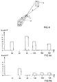
- the value of the corresponding distance interval is incremented and a maximum filtering is then carried out in such a way that, depending on which distance is greater, either the highest distance interval with a point frequency of greater than 1 or the highest distance interval with a point frequency of at least 1 and occupying the two lower ones Neighbor fields is selected to rule out random errors.
- Two corresponding distance histograms for a visual range of 160 m are shown in FIG. 5.
Landscapes
- Engineering & Computer Science (AREA)
- Physics & Mathematics (AREA)
- General Physics & Mathematics (AREA)
- Theoretical Computer Science (AREA)
- Computer Vision & Pattern Recognition (AREA)
- Analytical Chemistry (AREA)
- General Health & Medical Sciences (AREA)
- Biochemistry (AREA)
- Immunology (AREA)
- Pathology (AREA)
- Chemical & Material Sciences (AREA)
- Multimedia (AREA)
- Life Sciences & Earth Sciences (AREA)
- Health & Medical Sciences (AREA)
- Geometry (AREA)
- Image Analysis (AREA)
- Traffic Control Systems (AREA)
- Length Measuring Devices By Optical Means (AREA)
Abstract
Description
Die Erfindung betrifft ein Verfahren zur Ermittlung der Sichtweite, insbesondere für die Bewegung eines Kraftfahrzeuges, mittels Bildverarbeitung.The invention relates to a method for determining the visual range, in particular for the movement of a motor vehicle, by means of image processing.
Der größte Anteil der Informationen, die zum Führen eines Kraftfahrzeuges notwendig sind, werden visuell aufgenommen. Die Bedeutung der Fahrersicht wird besonders durch die Folgen deutlich, wenn das visuelle System für den Fahrer quasi ausfällt, dieses ist beispielsweise bei dichtem Nebel oder Dunkelheit der Fall. Bei der Abschätzung der momentanen Sichtweite durch den Fahrer treten oft große Fehler auf, die wachsen, wenn die Leitpfosten am Straßenrand als Referenzmaß fehlen. Aber auch mit dieser Referenz können sich starke Fehleinschätzungen ergeben, da der Verschmutzungsgrad der Leitpfosten stark schwanken kann. Aus diesem Grund ergibt sich die Aufgabe, eine Möglichkeit zur fahrzeugautonomen Sichtweitendetektion zu schaffen. Diese Unterstützung ist aber nicht nur für einen menschlichen Fahrer wichtig, sondern auch für vollautomatische Fahrzeugführungssysteme.Most of the information required to drive a motor vehicle is recorded visually. The importance of the driver's view is particularly clear from the consequences if the visual system for the driver virtually fails, which is the case, for example, in thick fog or darkness. When estimating the current line of sight by the driver, there are often large errors that increase when the roadside guide posts are missing as a reference measure. But even with this reference, strong misjudgments can result, since the degree of contamination of the guide posts can fluctuate greatly. For this reason, the task arises to create a possibility for vehicle-autonomous visibility detection. This support is not only important for a human driver, but also for fully automatic vehicle guidance systems.
Aus dem Stand der Technik sind verschiedene Systeme zur Sichtweitendetektion bekannt. So beschreibt die Deutsche Patentschrift DE 37 35 267 C2 eine Vorrichtung zur Sichtweitenmessung mit einem Lichtemitter, vorzugsweise einer Laserdiode, sowie einem Lichtsensor, die innerhalb des Kraftfahrzeuges an einem Rückspiegel angeordnet sind. Die Laserdiode erzeugt zeitlich extrem kurze Lichtblitze, deren Lichtstrahlen in Fahrtrichtung auf einen Bereich der Windschutzscheibe gerichtet sind. Je nach dem Verschmutzungsgrad der Windschutzscheibe wird ein mehr oder weniger großer Anteil des emittierten Licht an der Windschutzscheibe rückgestreut. Darüber hinaus wird auch von dem die Windschutzscheibe durchsetzenden Lichtes ein mehr oder weniger große Anteil rückgestreut, wenn das Kraftfahrzeug durch ein Nebelgebiet fährt bzw. sich einer Nebelwand annähert oder wenn die Sichtverhältnisse durch andere Schwebestoffe in der Atmosphäre, beispielsweise durch Rauch eingeschränkt sind. Die rückgestreuten Lichtstrahlen fallen teilweise auf den Lichtsensor, der ein Signal abgibt, welches den Pegel der jeweils aufgefangenen Lichtintensität wiedergibt. Dabei ist die Sichtweite um so schlechter, je größer die Intensität der zurückgestreuten Lichtstrahlen ist. Die beschriebene Vorrichtung ermittelt die Sichtweite nur indirekt in Abhängigkeit von Transmissionen in der Atmosphäre bzw. vom Verschmutzungsgrad der Windschutzscheibe, wobei nur die rückgestreuten Strahlen, die auf den Lichtsensor fallen, aufgewertet werden können.Various systems for visual range detection are known from the prior art. For example, German Patent DE 37 35 267 C2 describes a device for measuring the range of vision with a light emitter, preferably a laser diode, and a light sensor, which are arranged inside the motor vehicle on a rear view mirror. The laser diode generates extremely short flashes of light, the light rays of which are directed towards an area of the windshield in the direction of travel. Depending on the degree of contamination of the windshield, a more or less large proportion of the emitted light is scattered back onto the windshield. In addition, a greater or lesser proportion of the light passing through the windshield is also scattered back when the motor vehicle drives through a foggy area or approaches a wall of fog, or when visibility is restricted by other suspended substances in the atmosphere, for example smoke. The backscattered light rays fall partially on the light sensor, which emits a signal that reflects the level of the light intensity in each case. The greater the intensity of the backscattered light rays, the worse the visibility. The device described only determines the visual range indirectly as a function of transmissions in the atmosphere or the degree of soiling of the windshield, it being possible for only the backscattered rays which strike the light sensor to be upgraded.
Ein anderes, auf der Auswertung von ausgesendeten Lichtstrahlen basierendes Verfahren zur Ermittlung der Sichtweite ist aus der Deutschen Patentschrift DE 38 10 840 C1 bekannt. Das beschriebene System weist eine Einrichtung auf, die unter Verwendung eines optischen Pulsradars oder Dauerstrich-Radars und einer Entferungsmessung nach dem Laufzeitmeßverfahren die physikalische Sichtweite aus Faktoren, die sich aus Transmissionen der Atmosphäre, einem Signal eines Helligkeitssensors und einem Scheinwerfersignal die physikalische Sichtweite ermittelt. Auch dieses Verfahren basiert hauptsächlich auf der Messung des Rückstreuanteils aufgrund von in der Atmosphäre befindlicher Partikel, wobei für den Fall der Dunkelheit in die Sichtweitenberechnung die Einflußgröße Helligkeit über das Scheinwerfersignal und den Helligkeitssensor einfließt. Allerdings leuchten die Scheinwerfer, insbesondere bei Abblendlicht, den Straßenraum nicht vollständig aus, so daß die Sichtweite im Fall für nicht selbstleuchtende Sehziele nur innerhalb des Scheinwerferkegels liegen kann.Another method based on the evaluation of emitted light rays for determining the visibility is known from German Patent DE 38 10 840 C1. The system described has a device which, using an optical pulse radar or continuous wave radar and a distance measurement according to the transit time measurement method, determines the physical visibility from factors which are determined from transmissions in the atmosphere, a signal from a brightness sensor and a headlight signal to determine the physical visibility. This method too is mainly based on the measurement of the backscatter fraction due to particles in the atmosphere, with the influencing variable brightness being included in the visibility range calculation in the case of darkness via the headlight signal and the brightness sensor. However, the headlights illuminate the street area, especially in the case of low beam not completely off, so that the range of vision in the case of non-self-illuminating vision targets can only lie within the headlight cone.
Die Aufgabe der Erfindung besteht demgemäß darin, ein Verfahren, das mittels Bildverarbeitung eine genaue dem menschlichen Sehen nahekommende Sichtweitenermittlung durchführt, zu schaffen.The object of the invention is accordingly to provide a method which uses image processing to carry out a precise determination of the range of vision which is close to human vision.
Die Aufgabe wird durch die Merkmale des Patentanspruchs gelöst. Vorteilhafte Weiterbildungen sind in den Unteransprüchen dargestellt.The object is achieved by the features of the patent claim. Advantageous further developments are presented in the subclaims.
Erfindungsgemäß werden die von mindestens einer optoelektronischen Aufnahmeeinrichtung aufgenommenen Originalbilder in Bildmerkmale transformiert, die Orte von definierten Helligkeitsänderungen in den aufgenommenen Originalbildern kennzeichnen. Über eine Entfernungsbestimmung der Bildmerkmale relativ zu der optoelektronischen Aufnahmeeinrichtung und einer anschließenden Filterung der Entfernungswerte wird die aktuelle Sichtweite ermittelt.According to the invention, the original images recorded by at least one optoelectronic recording device are transformed into image features which identify locations of defined changes in brightness in the recorded original images. The current visual range is determined by determining the distance of the image features relative to the optoelectronic recording device and then filtering the distance values.
Von Vorteil ist dabei, daß keine Objekterkennung durchgeführt werden muß, sondern auch mit Objektkomponenten gearbeitet werden kann. Nach einer bevorzugten Ausführungsform der Erfindung stellen die Bildmerkmale Konturen von Objekten oder Objektausschnitten dar, die wiederum durch Geraden oder Geradenstücke angenähert werden können. Aus Gründen der zu verarbeitenden Datenmenge können die Bildmerkmale markante Punkte dieser Geraden, wie die Endpunkte oder die Schnittpunkte zweier Geraden, darstellen.The advantage here is that no object recognition has to be carried out, but can also be used with object components. According to a preferred embodiment of the invention, the image features represent contours of objects or object sections, which in turn can be approximated by straight lines or straight line segments. For reasons of the amount of data to be processed, the image features can represent striking points of this straight line, such as the end points or the intersection points of two straight lines.
Gemäß einer Ausgestaltung der Erfindung wird zur Ermittlung der Positionen der Bildmerkmale und damit auch ihrer Entfernung zu der optoelektronischen Aufnahmeeinrichtung ein Bewegungsstereo-Verfahren verwendet, wobei ein Vergleich der Position der Bildmerkmale in zwei nacheinander aufgenommenen Originalbildern erfolgt und aus der Differenz der Positionen jedes Bildmerkmals in den Originalbildern ein Verschiebungsvektor berechnet wird, aus dem unter Einbeziehung der Bewegung der optoelektronischen Aufnahmeeinrichtung die Position des dem Bildmerkmal zuordnenbaren Objektes bzw. Objektausschnittes ermittelt wird.According to one embodiment of the invention, a motion stereo method is used to determine the positions of the image features and thus also their distance from the optoelectronic recording device, a comparison of the position of the image features in two successively recorded original images takes place and a displacement vector is calculated from the difference between the positions of each image feature in the original images, from which the position of the object or object section that can be assigned to the image feature is determined, including the movement of the optoelectronic recording device.
Die Bewegung der optoelektronischen Aufnahmeeinrichtung wird aus Parametern der Fahrzeugbewegung, wie zum Beispiel der Fahrgeschwindigkeit, der Wank-, Quer- und/oder der Nickbewegung des Kraftfahrzeuges, berechnet.The movement of the optoelectronic recording device is calculated from parameters of the vehicle movement, such as the driving speed, the roll, transverse and / or the pitch movement of the motor vehicle.
Gemäß einer vorteilhaften Weiterbildung der Erfindung liefert die optoelektronische Aufnahmeeinrichtung kontinuierlich Originalbilder mit einer Frequenz im Bereich von 25 bis 30 Hz, die auf Bildmerkmale untersucht werden. Die von der optoelektronischen Aufnahmeeinrichtung erzeugten Originalbilder sind gemäß einer weiteren Ausbildung Grauwertbilder.According to an advantageous development of the invention, the optoelectronic recording device continuously delivers original images with a frequency in the range from 25 to 30 Hz, which are examined for image features. According to a further embodiment, the original images generated by the optoelectronic recording device are gray-scale images.
Die Erkennung bzw. Detektion der markanten Punkte im Originalbild kann vorteilhafterweise über bekannte Interest-Operatoren, wie den Moravec- oder den Dreschler-Operator, erfolgen, wobei in die Berechnung des Schwellwertes Faktoren der physiologischen Sehleistung des Fahrers einfließen können.The recognition or detection of the striking points in the original image can advantageously take place via known interest operators, such as the Moravec or the Dreschler operator, wherein factors of the driver's physiological visual performance can be included in the calculation of the threshold value.
Die aktuelle Sichtweite wird aus den Entfernungen der Bildmerkmale vorteilhaft über eine Filterung mit einem Schwellwert ermittelt z. B. Maximumfilterung. Der Vorteil des erfindungsgemäßen, gegenüber herkömmlichen Verfahren besteht insbesondere darin, daß ohne aktive Sender zusätzlich zu Transmission der Atmosphäre der echte Sehobjektkontrast in die Ermittlung der Sichtweite einfließt.The current range of vision is advantageously determined from the distances of the image features by filtering with a threshold value, e.g. B. Maximum filtering. The advantage of the inventive method compared to conventional methods is, in particular, that without an active transmitter, in addition to transmission of the atmosphere, the real visual object contrast is included in the determination of the visual range.
Nachfolgend wird die Erfindung anhand von Ausführungsbeispielen näher beschreiben. Die zugehörigen Zeichnungen zeigen:
- Figur 1:
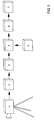
- eine schematische Darstellung der Verfahrensschritte,
- Figur 2:
- ein Bildausschnitt mit markanten Punkten,
- Figur 3:
- ein Bildausschnitt mit eingetragenen Verschiebungsvektoren,
- Figur 4:
- eine Darstellung der Suchraumeinschränkung und
- Figur 5:
- zwei Entfernungshistogramme.
- Figure 1:
- a schematic representation of the process steps,
- Figure 2:
- an image section with distinctive dots,
- Figure 3:
- an image section with entered displacement vectors,
- Figure 4:
- a representation of the search space restriction and
- Figure 5:
- two distance histograms.
Die Grundlage des erfindungsgemäßen Verfahrens sind Überlegungen, wie Menschen visuelle Informationen aufnehmen. Die mit den Augen aufgenommenen Bilder werden in grundlegende Bildmerkmale transformiert, die lediglich Orte von Identitätsänderungen des Originalbildes enthalten. Zur Aufnahme der Originalbilder wird eine CCD-Kamera 1 verwendet, die kontinuierlich Grauwertbilder mit einer Frequenz von 25 Hz liefert. Die in einem nachfolgenden Verfahrensschritt 2 auf markante Punkte P untersucht und deren Position gespeichert wird. Im anschließenden Verfahrensschritt 3 erfolgt die Zuordnung der markanten Punkte P eines ersten aufgenommenen Originalbildes in einem nachfolgenden zweiten Originalbild über ein Bewegungsstereo-Verfahren. Durch die so entstandenen Verschiebungsvektoren der markanten Punkte P kann mit dem Wissen der Fahrzeugbewegung 5 im Verfahrenschritt 4 die Position der markanten Punkte relativ zur CCD-Kamera 1 berechnet werden. Im letzten Schritt 6 werden die Entfernungen der markanten Punkte hinsichtlich einer maximalen Entfernung gefiltert, was dann ein Maß für die Sichtweite 7 ist.The method according to the invention is based on considerations of how people record visual information. The images taken with the eyes are transformed into basic image features that only contain locations of changes in identity of the original image. A
Nachfolgend werden die einzelnen Verfahrenschritte näher erläutert. Für die Detektierung der markanten Punkte werden lokale Gebiete bzw. Punkte, die eine steile Autokorrelationsfunktion besitzen, benötigt, um diese im nächsten Originalbild wiederfinden zu können. Der Moravec-Operator bzw. der modifizierte Moravec-Operator bewertet lokalgerichtete Grauwert-Varianzen.The individual process steps are explained in more detail below. Local areas or points that have a steep autocorrelation function are required for the detection of the striking points in order to be able to find them again in the next original image. The Moravec operator or the modified Moravec operator evaluates locally directed gray value variances.
Der Ablauf ist folgendermaßen: innerhalb einer gewählten Operatorgröße werden Quadrate der Grauwertdifferenzen benachbarter Pixel in verschiedenen Richtungen addiert. Der erhaltene Operator wird als das Minimum der Richtungsvarianten definiert und wird dem betrachteten Pixel zugeordnet. Als markante Punkte werden nun alle lokalen Maxima des Operatorwertes detektiert, die einen ausgewählten Schwellwert überschreiten. Figur 2 zeigt ein Originalbild einer realen Verkehrsszene mit detektierten markanten Punkten P.The process is as follows: within a selected operator size, squares of the gray value differences of neighboring pixels are added in different directions. The operator obtained is defined as the minimum of the directional variants and is assigned to the pixel under consideration. All local maxima of the operator value that exceed a selected threshold value are now detected as distinctive points. Figure 2 shows an original image of a real traffic scene with detected striking points P.
Ein weiterer, einsetzbarer Interest-Operator ist der sogenannte Dreschler-Operator. Der Gedanke des Dreschler-Operators liegt darin, nicht mit Grauwertdifferenzen, sondern direkt mit lokalen Krümmungen die differentialgeometrischen Eigenschaften der Bildfunktion zur Erfassen. Basierend auf den 2. Ableitungen der Bildfunktion werden die Haupt- bzw. Gaußschen Krümmungen berechnet und über eine Interpretation der lokalen Krümmungsextrema markante Punkte bestimmt. Dabei wird die Merkmalsstruktur genau beschrieben.Another usable interest operator is the so-called Dreschler operator. The idea behind the Dreschler operator is not to use gray value differences, but rather local curvatures to capture the differential-geometric properties of the image function. The main or Gaussian curvatures are calculated based on the second derivatives of the image function and distinctive points are determined by an interpretation of the local curvature extremes. The feature structure is described in detail.
Über den Verfahrensschritt 3, Zuordnung der markanten Punkte P aus zwei nacheinander aufgenommenen Originalbildern wird ein Verschiebungsvektorfeld abgeleitet, mit dem dann die eigentliche Entfernungsbestimmung 4 durchgeführt werden kann. Dafür ist in dem zweiten Bild der korrespondierende Punkt P' bezüglich eines detektierten markanten Punktes P aus dem ersten Originalbild zu bestimmen bzw. umgekehrt. Bei dem Verfahren wird von der Erkenntnis ausgegangen, wenn bei einer Bewegung, deren Bewegungsrichtung identisch mit der Blickrichtung ist, sich alle ortsfesten Bildpunkte P; P' radial von einem gedachten Punkt, dem Expansionszentrum E, nach außen zum Bildrand bewegen, wobei die relative Geschwindigkeit, mit der sich ein Punkt bewegt, umgekehrt proportional zu seiner pysikalischen Entfernung von der Aufnahmeeinrichtung ist. Entsprechend der zugehörigen Objektposition sind die Verschiebungsvektoren der markanten Punkte P unterschiedlich lang. Bildmerkmale von nicht ortsfesten Objekten, zum Beispiel von anderen Fahrzeugen, erzeugen Verschiebungsvektoren, die in ihrer Richtung nicht radial von dem Expansionszentrum nach außen zeigen, wodurch zwischen ortsfesten und nicht ortsfesten Punkten unterschieden werden kann. Eine prinzipielle Darstellung der Bewegung der ortsfesten Punkte P und der nicht ortsfesten Punkte N bezüglich des Expansionszentrums E ist in Figur 3 dargestellt.A displacement vector field is derived via
Bei einer Entfernungsbestimmung der ortsfesten markanten Punkte P muß einerseits die radiale Punktbewegung bezüglich des Expansionszentrums E andererseits auch die Eigenbewegungen des Kraftfahrzeuges berücksichtigt werden. Letzteres ist notwendig, da sich die mit dem Fahrzeug festverbundene CCD-Kamera nicht ideal in einer Richtung, der Fahrtrichtung bewegt, sondern bedingt durch Nick- und Wankbewegungen des Fahrzeuges die CCD-Kamera zusätzlich störende Eigenbewegungen ausführt. Aus diesem Grund wird sowohl um das Expansionszentrum E wie auch um den markanten Punkt P selbst ein Unsicherheitsbereich eingeführt. Dabei ist zu berücksichtigen, daß die Position des markanten Punktes P aus dem ersten Originalbild auf die im zweiten Originalbild veränderten Verhältnisse transformiert werden muß, was durch einen zum Originalpunkt P zugehörigen Translationsvektor T bewirkt wird. Es wird ein Suchraum aus der Vorhersage der Bewegung von ortsfesten Punkten sowie der Unsicherheitsbereiche aufgespannt. Die Suchraumlänge b wird adaptiv durch den Abstand a des markanten Punktes P zum Expansionszentrum E gesteuert, da nah am Expansionszentrum liegende Punkte kleinere Verschiebungsvektoren als weiter davon entfernte Punkte besitzen (Fig. 4). Ein solches Vorgehen bezweckt einerseits die Reduktion der Anzahl der markanten Punkte für die Korrespondenz als auch andererseits eine spezielle Filterung, welche ortsfeste Punkte extrahiert. Letzteres ist deshalb notwendig, da nicht ortsfeste Punkte für die Positionsauswertung mittels eines Bewegungsstereo-Verfahrens nicht herangezogen werden können, weil ihre Positionsänderung zwischen den Aufnahmen im allgemeinen unbekannt ist.When determining the distance of the fixed, distinctive points P, on the one hand the radial point movement with respect to the expansion center E and on the other hand the own movements of the motor vehicle must be taken into account. The latter is necessary because the CCD camera, which is firmly connected to the vehicle, does not ideally move in one direction, the direction of travel, but due to the vehicle's pitching and rolling movements, the CCD camera also performs its own disturbing movements. For this reason, an area of uncertainty is introduced around both the expansion center E and the striking point P itself. It must be taken into account here that the position of the distinctive point P from the first original image must be transformed to the conditions changed in the second original image, which is brought about by a translation vector T associated with the original point P. A search space is spanned from the prediction of the movement of fixed points and the areas of uncertainty. The search space length b is adaptively controlled by the distance a from the prominent point P to the expansion center E, since points close to the expansion center have smaller displacement vectors than points further away (FIG. 4). Such a procedure aims on the one hand to reduce the number of distinctive points for the correspondence and on the other hand to use special filtering which extracts fixed points. The latter is necessary because points that are not fixed cannot be used for position evaluation by means of a motion stereo method because their change in position between the recordings is generally unknown.
Die markanten Punkte P' im zweiten Originalbild, die innerhalb des beschriebenen Suchraums liegen sind potentielle Kandidaten für den korrespondierten Punkt P aus dem ersten Originalbild. Die Entscheidungsfindung, welcher markante Punkt aus dem zweiten Originalbild zum markanten Punkt aus dem ersten Originalbild korrespondiert, kann mit Hilfe von Algorithmen der FUZZY-Logic durchgeführt werden. Dabei einsetzbare Regeln sind:
- 1. die Position des Punktes P; P' bezüglich des Suchraums,
- 2. die Anzahl der markanten Punkte,
- 3. die Gaußsche Krümmung im Maximum,
- 4. die Strukturentwicklung beim Dreschler-Operator,
- 5. Anzahl der zugehörigen Minima beim Dreschler-Operator,
- 6. Mittelwert der Grauwert-Umgebung und
- 7. Überschreitung einer Mindestschwelle.
- 1. the position of point P; P 'with respect to the search space,
- 2. the number of striking points,
- 3. the Gaussian curvature at the maximum,
- 4. the structure development at the Dreschler operator,
- 5. number of associated minima for the Dreschler operator,
- 6. mean value of the gray value environment and
- 7. A minimum threshold is exceeded.
Bei der 4. Ähnlichkeitsregel handelt es sich um ein spezielles Verhalten des Dreschler-Operators. Sehr kleine, im Extremfall punktförmliche Bildstrukturen bestehen aus einem Maximum der Gaußschen Krümmung umgeben von mehreren Minima. Werden diese Strukturen größer, was der Fall ist, wenn man sich nähert, so werden diese Strukturen ausgeprägter, woraus resultiert, daß die Anzahl der das Maximum umgebundenen Minima sinkt, im Extremfall auf ein Minimum bei einer Ecke. Hieraus wird geschlossen, daß sich die Kamera auf die Punkte zu bewegt.The 4th similarity rule is a special behavior of the Dreschler operator. Very small, in extreme cases punctiform image structures consist of a maximum of the Gaussian curvature surrounded by several minima. If these structures become larger, which is the case when one approaches, these structures become more pronounced, with the result that the number of the minima bound around the maximum decreases, in extreme cases to a minimum at one corner. From this it is concluded that the camera is moving towards the points.
Anhand der Ergebnisse oben genannten Regeln wird für jeden im Suchraum B liegenden markanten Punkt P' im zweiten Originalbild ein Bewertungsmaß bezüglich seiner Ähnlichkeit zu dem markanten Punkt P des ersten Originalbildes berechnet. Das Ergebnis sind Verschiebungsfaktoren von ortsfesten Punkten, die sich aus der Änderung der Kameraposition ergeben.On the basis of the results of the above-mentioned rules, for each distinctive point P 'in the search space B in the second original image, an assessment measure is made regarding its similarity to the distinctive one Point P of the first original image is calculated. The result is displacement factors from fixed points, which result from the change in the camera position.
Über den Verschiebungsvektor eines ortsfesten markanten Punktes P, der durch das Punktpaar P und P' aufgespannt wird, wird unter Berücksichtigung der Fahrzeugbewegung mit Gieren, Nicken und Wanken die Entfernung eines dem markanten Punkt P zugehörigen Objektes oder Objektkomponente berechnet und in ein Entfernungshistogramm eingetragen. Da sich das Fahrzeug bzw. die CCD-Kamera während der Aufnahme der Bilder dem markanten Punkt P genähert hat, ist dabei die Entfernungsberechnung auf dem markanten Punkt P' im zweiten Originalbild zu beziehen.Using the displacement vector of a fixed, distinctive point P, which is spanned by the pair of points P and P ', the distance of an object or object component belonging to the prominent point P is calculated taking into account the vehicle movement with yaw, pitching and swaying and entered in a distance histogram. Since the vehicle or the CCD camera has approached the distinctive point P during the recording of the images, the distance calculation must be based on the distinctive point P 'in the second original image.
Die Sichtweite wird im nächsten Verfahrensschnitt aus der Entfernungsverteilung der zu den erkannten markanten Punkten zugehörigen Objekten, deren photometrischer Kontrast somit größer als ein definierter Schwellwert, z. B. der physiologische Schwellenkontrast des menschlichen Auges, ist, bestimmt. Da für die Sichtweite aufgrund ihres Bereichsverständnisses die Größenordnung wesentlich wichtiger ist, als ein exakter Wert, wird die Sichtweite nach dem Ausführungsbeispiel in Intervallen s = 10 m ermittelt. Der Ablauf der Auswertung geschieht deshalb mittels einer Intervallorganisation, die durch ihre Struktur eine lokale Tiefpaßcharakteristik besitzt, wodurch Ergebnisschwankungen reduziert werden. So wird für jedes Merkmal der Wert des entsprechenden Entfernungsintervalls inkrementiert und anschließend eine Maximumfilterung derart durchgeführt, daß je nachdem welche Entfernung größer ist, entweder das höchste Entfernungsintervall mit einer Punkthäufigkeit von größer 1 oder das höchste Entfernungsintervall in einer Punkthäufigkeit von mindestens 1 und besetzten beiden unteren Nachbarfeldern ausgewählt wird, um zufällige Fehler auszuschließen. Zwei entsprechende Entfernungshistogramme für eine Sichtweite von 160 m ist in Figur 5 dargestellt.In the next section of the method, the range of vision is determined from the distance distribution of the objects belonging to the recognized striking points, the photometric contrast of which is thus greater than a defined threshold value, e.g. B. the physiological threshold contrast of the human eye is determined. Since the order of magnitude is much more important than an exact value for the range of vision due to its understanding of the area, the range of vision is determined according to the exemplary embodiment in intervals s = 10 m. The evaluation is therefore carried out by means of an interval organization, which has a local low-pass characteristic due to its structure, which reduces fluctuations in results. For each characteristic, the value of the corresponding distance interval is incremented and a maximum filtering is then carried out in such a way that, depending on which distance is greater, either the highest distance interval with a point frequency of greater than 1 or the highest distance interval with a point frequency of at least 1 and occupying the two lower ones Neighbor fields is selected to rule out random errors. Two corresponding distance histograms for a visual range of 160 m are shown in FIG. 5.
- 11
- elektronische Bildaufnahmeeinrichtungelectronic image recording device
- 22nd
- DetektionDetection
- 33rd
- Zuordnung markanter PunkteAllocation of distinctive points
- 44th
- EnternungsbestimmungDeforestation determination
- 55
- FahrzeugbewegungVehicle movement
- PP
- markante Punkte eines ersten Originalbildesstriking points of a first original picture
- P'P '
- markante Punkte eines zweiten Originalbildesstriking points of a second original picture
- EE
- ExpansionszentrumExpansion center
- NN
- nicht ortsfeste Punktenot fixed points
- TT
- TranslationsvektorTranslation vector
- bb
- SuchraumlängeSearch space length
- aa
- Abstand vom ExpansionszentrumDistance from the expansion center
Claims (17)
Applications Claiming Priority (2)
| Application Number | Priority Date | Filing Date | Title |
|---|---|---|---|
| DE4423604 | 1994-07-06 | ||
| DE4423604 | 1994-07-06 |
Publications (2)
| Publication Number | Publication Date |
|---|---|
| EP0691534A1 true EP0691534A1 (en) | 1996-01-10 |
| EP0691534B1 EP0691534B1 (en) | 2001-12-12 |
Family
ID=6522329
Family Applications (1)
| Application Number | Title | Priority Date | Filing Date |
|---|---|---|---|
| EP95108569A Expired - Lifetime EP0691534B1 (en) | 1994-07-06 | 1995-06-03 | Method of visibility determination in particular for vehicle movement |
Country Status (3)
| Country | Link |
|---|---|
| US (1) | US5987152A (en) |
| EP (1) | EP0691534B1 (en) |
| DE (1) | DE59509929D1 (en) |
Cited By (16)
| Publication number | Priority date | Publication date | Assignee | Title |
|---|---|---|---|---|
| EP1067399A2 (en) * | 1999-06-24 | 2001-01-10 | Robert Bosch Gmbh | Method of visibility determination |
| WO2002006851A1 (en) * | 2000-07-15 | 2002-01-24 | Robert Bosch Gmbh | Method for determining visibility |
| EP1069536A3 (en) * | 1999-07-14 | 2002-02-06 | Fuji Jukogyo Kabushiki Kaisha | Stereo type vehicle monitoring apparatus with fail-safe function |
| WO2003066375A1 (en) * | 2002-02-08 | 2003-08-14 | Robert Bosch Gmbh | Device for automatically adjusting the brightness of a luminous beam emitted by the rear lighting equipment on a vehicle |
| FR2839787A1 (en) * | 2002-05-15 | 2003-11-21 | Peugeot Citroen Automobiles Sa | Visibility sensor for cars has optical target on windscreen viewed by camera on telescopic mount |
| DE102006005231A1 (en) * | 2006-02-02 | 2007-08-16 | Optotransmitter-Umweltschutz-Technologie E.V. | Method for determination of distance of an object, involves stereoscopic analysis of two picture fields comprising digital camera pictures, which are recorded by stationary camera system |
| EP2050644A1 (en) * | 2007-10-18 | 2009-04-22 | Renault S.A.S. | Methods for measuring the visibility of an automobile driver and calculating speed instructions for the vehicle, and method for implementing same |
| EP1962245A3 (en) * | 2007-02-21 | 2009-06-24 | Hella KGaA Hueck & Co. | Method and device for detecting the movement state of objects |
| DE102008051593A1 (en) * | 2008-10-14 | 2010-04-15 | Bayerische Motoren Werke Aktiengesellschaft | Vehicle's visibility measurement determining method, involves transforming light distribution into perspective view of position such that another light distribution is retained, and determining measurements from latter light distribution |
| US8077921B2 (en) | 2007-01-11 | 2011-12-13 | Denso Corporation | Apparatus for determining the presence of fog using image obtained by vehicle-mounted imaging device |
| DE102011105074A1 (en) | 2011-06-21 | 2011-12-22 | Daimler Ag | Method for determining visual range for vehicle, involves determining surrounding of vehicle by camera, where contrast dimensions are determined for object depicted in images, where visual range is determined from contrast dimensions |
| EP2562042A1 (en) * | 2011-08-23 | 2013-02-27 | Robert Bosch Gmbh | Method for determining a range of at least one headlamp and method for calibrating a light emission from at least one headlamp of a vehicle |
| US8786697B2 (en) | 2007-01-11 | 2014-07-22 | Denso Corporation | Apparatus for determining the presence of fog using image obtained by vehicle-mounted imaging device |
| DE102014212216A1 (en) * | 2014-06-17 | 2015-12-17 | Conti Temic Microelectronic Gmbh | Method and driver assistance system for detecting a Fahrzeugumfel des |
| US9952058B2 (en) | 2016-08-29 | 2018-04-24 | Denso International America, Inc. | Driver visibility detection system and method for detecting driver visibility |
| US11482101B2 (en) | 2017-10-19 | 2022-10-25 | Continental Automotive Gmbh | Method for generating a visual range collection and visual range collecting device |
Families Citing this family (35)
| Publication number | Priority date | Publication date | Assignee | Title |
|---|---|---|---|---|
| JP4672094B2 (en) * | 1999-01-22 | 2011-04-20 | ソニー株式会社 | Image processing apparatus and method, and recording medium |
| US7016045B2 (en) * | 1999-03-12 | 2006-03-21 | Regents Of The University Of Minnesota | Video camera-based visibility measurement system |
| US6853453B2 (en) * | 1999-03-12 | 2005-02-08 | Regents Of The University Of Minnesota | Video camera-based visibility measurement system |
| JP3853542B2 (en) * | 1999-07-26 | 2006-12-06 | パイオニア株式会社 | Image processing apparatus, image processing method, and navigation apparatus |
| US6704621B1 (en) * | 1999-11-26 | 2004-03-09 | Gideon P. Stein | System and method for estimating ego-motion of a moving vehicle using successive images recorded along the vehicle's path of motion |
| AU2001253619A1 (en) * | 2000-04-14 | 2001-10-30 | Mobileye, Inc. | Generating a model of the path of a roadway from an image recorded by a camera |
| US7113867B1 (en) | 2000-11-26 | 2006-09-26 | Mobileye Technologies Limited | System and method for detecting obstacles to vehicle motion and determining time to contact therewith using sequences of images |
| FR2835911B1 (en) * | 2002-02-14 | 2004-05-07 | France Etat Ponts Chaussees | METHOD FOR DETERMINING THE DISTANCE OF VISISBILITY AND METHOD FOR DETERMINING THE PRESENCE OF A FOG |
| DE10219788C1 (en) * | 2002-05-03 | 2003-11-13 | Bosch Gmbh Robert | Method and device for measuring visibility with image sensor systems |
| AU2003281400A1 (en) * | 2002-07-03 | 2004-01-23 | Iwane Laboratories, Ltd. | Automatic guide apparatus for public transport |
| FR2847367B1 (en) * | 2002-11-19 | 2005-01-14 | Valeo Vision | METHOD AND DEVICE FOR DETERMINING THE VISIBILITY DISTANCE OF THE DRIVER OF A VEHICLE |
| EP3454315A1 (en) | 2004-04-08 | 2019-03-13 | Mobileye Vision Technologies Ltd. | Collision warning system |
| FR2876826B1 (en) * | 2004-10-19 | 2007-03-02 | France Etat Ponts Chaussees | DEVICE FOR MEASURING VISIBILITY DISTANCE |
| US7270229B2 (en) * | 2004-11-05 | 2007-09-18 | New England Machinery, Inc. | Container unscrambler system having adjustable track and method |
| JP4608631B2 (en) * | 2005-06-08 | 2011-01-12 | 国立大学法人名古屋大学 | Image processing device for vehicle, driving support device |
| DE102005035812A1 (en) * | 2005-07-27 | 2007-02-08 | Adc Automotive Distance Control Systems Gmbh | Method of detecting soiling on a transparent pane |
| DE102005035810A1 (en) * | 2005-07-27 | 2007-02-01 | Adc Automotive Distance Control Systems Gmbh | Method of determining visibility with a camera |
| US7538800B1 (en) * | 2005-09-27 | 2009-05-26 | The United States Of America As Represented By The Secretary Of The Army | Methods and apparatus for assessing visibility through an optical material |
| JP4725391B2 (en) * | 2006-03-29 | 2011-07-13 | 株式会社デンソー | Visibility measuring device for vehicle and driving support device |
| US7786898B2 (en) | 2006-05-31 | 2010-08-31 | Mobileye Technologies Ltd. | Fusion of far infrared and visible images in enhanced obstacle detection in automotive applications |
| FR2902556B1 (en) * | 2006-06-15 | 2008-08-15 | Valeo Vision Sa | METHOD FOR DETERMINING A VISIBILITY DISTANCE FOR A DRIVER OF A VEHICLE |
| US8600656B2 (en) * | 2007-06-18 | 2013-12-03 | Leddartech Inc. | Lighting system with driver assistance capabilities |
| US8416300B2 (en) * | 2009-05-20 | 2013-04-09 | International Business Machines Corporation | Traffic system for enhancing driver visibility |
| DE112010001879A5 (en) | 2009-07-06 | 2012-10-11 | Conti Temic Microelectronic Gmbh | Optical module for simultaneous focusing on two viewing areas |
| DE102009046597A1 (en) | 2009-11-11 | 2011-05-12 | Robert Bosch Gmbh | Light detecting and ranging system's atmospheric influences reducing method for driver assistant system for detecting pedestrian in surrounding of motor vehicle, involves determining whether object is stationary object or movable object |
| CN101860677A (en) * | 2010-06-04 | 2010-10-13 | 西安天和防务技术股份有限公司 | Fog-penetrating and night-vision system based on refrigeration type CCD element |
| KR101903981B1 (en) | 2010-11-30 | 2018-10-05 | 콘티 테믹 마이크로일렉트로닉 게엠베하 | Detection of raindrops on a pane by means of a camera and lighting |
| DE102011103302A1 (en) | 2011-06-03 | 2012-12-06 | Conti Temic Microelectronic Gmbh | Camera system for a vehicle |
| DE102011056051A1 (en) | 2011-12-05 | 2013-06-06 | Conti Temic Microelectronic Gmbh | Method for evaluating image data of a vehicle camera taking into account information about rain |
| DE102012103873A1 (en) | 2012-05-03 | 2013-11-21 | Conti Temic Microelectronic Gmbh | Detecting raindrops on a glass by means of a camera and lighting |
| DE102014209197A1 (en) | 2014-05-15 | 2015-11-19 | Conti Temic Microelectronic Gmbh | Apparatus and method for detecting precipitation for a motor vehicle |
| EP3215807B1 (en) | 2014-11-06 | 2020-04-15 | Gentex Corporation | System and method for visibility range detection |
| DE102015112103A1 (en) | 2015-07-24 | 2017-01-26 | Preh Gmbh | Detection device for detecting fog for a motor vehicle |
| CN105554358A (en) * | 2016-01-29 | 2016-05-04 | 成都科创谷科技有限公司 | Intelligent image collection device with anti-fog function |
| US10803570B2 (en) | 2018-05-10 | 2020-10-13 | Eagle Technology, Llc | Method and system for a measure of visibility from a single daytime image |
Citations (7)
| Publication number | Priority date | Publication date | Assignee | Title |
|---|---|---|---|---|
| US4216498A (en) * | 1978-09-12 | 1980-08-05 | Sri International | Visibility monitor employing television camera |
| DE3801368A1 (en) * | 1988-01-19 | 1989-07-27 | Spies Martin J Dipl Ing Fh | Visual range meter |
| DE3810840C1 (en) | 1988-03-30 | 1989-11-09 | Messerschmitt-Boelkow-Blohm Gmbh, 8012 Ottobrunn, De | |
| DE3735267C2 (en) | 1987-10-17 | 1990-08-23 | Daimler-Benz Aktiengesellschaft, 7000 Stuttgart, De | |
| EP0390640A1 (en) * | 1989-03-29 | 1990-10-03 | General Electric Cgr S.A. | Method for automatic image matching |
| EP0444402A2 (en) * | 1990-02-24 | 1991-09-04 | ELTRO GmbH Gesellschaft für Strahlungstechnik | Method and apparatus for indicating visibility in fog to drivers of motor vehicles |
| DE4301228C1 (en) * | 1993-01-19 | 1994-04-21 | Daimler Benz Ag | Procedure for determining visibility |
Family Cites Families (2)
| Publication number | Priority date | Publication date | Assignee | Title |
|---|---|---|---|---|
| US4969036A (en) * | 1989-03-31 | 1990-11-06 | Bir Bhanu | System for computing the self-motion of moving images devices |
| US5179441A (en) * | 1991-12-18 | 1993-01-12 | The United States Of America As Represented By The Administrator Of The National Aeronautics And Space Administration | Near real-time stereo vision system |
-
1995
- 1995-06-03 EP EP95108569A patent/EP0691534B1/en not_active Expired - Lifetime
- 1995-06-03 DE DE59509929T patent/DE59509929D1/en not_active Expired - Lifetime
-
1997
- 1997-11-18 US US08/972,692 patent/US5987152A/en not_active Expired - Lifetime
Patent Citations (7)
| Publication number | Priority date | Publication date | Assignee | Title |
|---|---|---|---|---|
| US4216498A (en) * | 1978-09-12 | 1980-08-05 | Sri International | Visibility monitor employing television camera |
| DE3735267C2 (en) | 1987-10-17 | 1990-08-23 | Daimler-Benz Aktiengesellschaft, 7000 Stuttgart, De | |
| DE3801368A1 (en) * | 1988-01-19 | 1989-07-27 | Spies Martin J Dipl Ing Fh | Visual range meter |
| DE3810840C1 (en) | 1988-03-30 | 1989-11-09 | Messerschmitt-Boelkow-Blohm Gmbh, 8012 Ottobrunn, De | |
| EP0390640A1 (en) * | 1989-03-29 | 1990-10-03 | General Electric Cgr S.A. | Method for automatic image matching |
| EP0444402A2 (en) * | 1990-02-24 | 1991-09-04 | ELTRO GmbH Gesellschaft für Strahlungstechnik | Method and apparatus for indicating visibility in fog to drivers of motor vehicles |
| DE4301228C1 (en) * | 1993-01-19 | 1994-04-21 | Daimler Benz Ag | Procedure for determining visibility |
Cited By (23)
| Publication number | Priority date | Publication date | Assignee | Title |
|---|---|---|---|---|
| EP1067399A2 (en) * | 1999-06-24 | 2001-01-10 | Robert Bosch Gmbh | Method of visibility determination |
| EP1067399A3 (en) * | 1999-06-24 | 2003-11-26 | Robert Bosch Gmbh | Method of visibility determination |
| EP1069536A3 (en) * | 1999-07-14 | 2002-02-06 | Fuji Jukogyo Kabushiki Kaisha | Stereo type vehicle monitoring apparatus with fail-safe function |
| WO2002006851A1 (en) * | 2000-07-15 | 2002-01-24 | Robert Bosch Gmbh | Method for determining visibility |
| US7274386B2 (en) | 2000-07-15 | 2007-09-25 | Robert Bosch Gmbh | Method for determining visibility |
| WO2003066375A1 (en) * | 2002-02-08 | 2003-08-14 | Robert Bosch Gmbh | Device for automatically adjusting the brightness of a luminous beam emitted by the rear lighting equipment on a vehicle |
| FR2839787A1 (en) * | 2002-05-15 | 2003-11-21 | Peugeot Citroen Automobiles Sa | Visibility sensor for cars has optical target on windscreen viewed by camera on telescopic mount |
| DE102006005231A1 (en) * | 2006-02-02 | 2007-08-16 | Optotransmitter-Umweltschutz-Technologie E.V. | Method for determination of distance of an object, involves stereoscopic analysis of two picture fields comprising digital camera pictures, which are recorded by stationary camera system |
| DE102008003948B4 (en) * | 2007-01-11 | 2013-10-31 | Denso Corporation | An apparatus for determining the presence of fog using an image obtained by a vehicle-mounted imaging device |
| US8077921B2 (en) | 2007-01-11 | 2011-12-13 | Denso Corporation | Apparatus for determining the presence of fog using image obtained by vehicle-mounted imaging device |
| US8786697B2 (en) | 2007-01-11 | 2014-07-22 | Denso Corporation | Apparatus for determining the presence of fog using image obtained by vehicle-mounted imaging device |
| EP1962245A3 (en) * | 2007-02-21 | 2009-06-24 | Hella KGaA Hueck & Co. | Method and device for detecting the movement state of objects |
| EP2050644A1 (en) * | 2007-10-18 | 2009-04-22 | Renault S.A.S. | Methods for measuring the visibility of an automobile driver and calculating speed instructions for the vehicle, and method for implementing same |
| FR2922506A1 (en) * | 2007-10-18 | 2009-04-24 | Renault Sas | METHODS FOR MEASURING THE VISIBILITY DISTANCE OF A MOTOR VEHICLE DRIVER AND CALCULATING A VEHICLE SPEED SET, AND SYSTEMS FOR THEIR IMPLEMENTATION |
| DE102008051593A1 (en) * | 2008-10-14 | 2010-04-15 | Bayerische Motoren Werke Aktiengesellschaft | Vehicle's visibility measurement determining method, involves transforming light distribution into perspective view of position such that another light distribution is retained, and determining measurements from latter light distribution |
| DE102008051593B4 (en) * | 2008-10-14 | 2021-03-11 | Bayerische Motoren Werke Aktiengesellschaft | Method and system for determining the visibility of a vehicle |
| DE102011105074A1 (en) | 2011-06-21 | 2011-12-22 | Daimler Ag | Method for determining visual range for vehicle, involves determining surrounding of vehicle by camera, where contrast dimensions are determined for object depicted in images, where visual range is determined from contrast dimensions |
| EP2562042A1 (en) * | 2011-08-23 | 2013-02-27 | Robert Bosch Gmbh | Method for determining a range of at least one headlamp and method for calibrating a light emission from at least one headlamp of a vehicle |
| US8941303B2 (en) | 2011-08-23 | 2015-01-27 | Robert Bosch Gmbh | Method for determining an illumination range of at least one headlight and method for calibrating a light emission of at least one headlight of a vehicle |
| DE102011081392B4 (en) | 2011-08-23 | 2023-01-26 | Robert Bosch Gmbh | Method for calibrating a light emission of at least one headlight of a vehicle |
| DE102014212216A1 (en) * | 2014-06-17 | 2015-12-17 | Conti Temic Microelectronic Gmbh | Method and driver assistance system for detecting a Fahrzeugumfel des |
| US9952058B2 (en) | 2016-08-29 | 2018-04-24 | Denso International America, Inc. | Driver visibility detection system and method for detecting driver visibility |
| US11482101B2 (en) | 2017-10-19 | 2022-10-25 | Continental Automotive Gmbh | Method for generating a visual range collection and visual range collecting device |
Also Published As
| Publication number | Publication date |
|---|---|
| DE59509929D1 (en) | 2002-01-24 |
| US5987152A (en) | 1999-11-16 |
| EP0691534B1 (en) | 2001-12-12 |
Similar Documents
| Publication | Publication Date | Title |
|---|---|---|
| EP0691534B1 (en) | Method of visibility determination in particular for vehicle movement | |
| EP1267178B1 (en) | Method for processing a high definition picture | |
| DE4341689B4 (en) | Device for detecting a vehicle ahead | |
| EP1067399B1 (en) | Method of visibility determination | |
| DE10114932B4 (en) | Three-dimensional environment detection | |
| DE102019120118A1 (en) | DEVICE AND METHOD FOR CONTROLLING THE DRIVING OF A VEHICLE | |
| EP1531343B1 (en) | Method for tracking objects | |
| EP1303768B1 (en) | Method for determining visibility | |
| DE19720764A1 (en) | Traffic detecting method for motor vehicle | |
| EP1531342B1 (en) | Method of detecting pedestrians | |
| EP1298454A2 (en) | Method for recognising and tracking objects | |
| DE10324895A1 (en) | Vehicle object location procedure for adaptive cruise control system car tracking, uses video mask matching in search field from radar sensor | |
| DE10252323A1 (en) | Method for determining an own movement of a vehicle | |
| DE102018008442A1 (en) | Method for weather and / or visibility detection | |
| EP1306690B1 (en) | Method for recognising and tracking objects | |
| WO2021239323A1 (en) | Method for identifying image artifacts, controller for carrying out such a method, identifying device comprising such a controller, and motor vehicle comprising such an identifying device | |
| EP1298012B1 (en) | Method for recognizing and tracking objects | |
| EP1419402A1 (en) | Method for detecting and tracking objects | |
| DE10148062A1 (en) | Localizing system for objects uses transmitter for pulsed emission of laser beams and receiver with sensor to pick up reflected beam pulses and to analyze them regarding their execution time | |
| DE10219788C1 (en) | Method and device for measuring visibility with image sensor systems | |
| DE102006037600B4 (en) | Method for the resolution-dependent representation of the environment of a motor vehicle | |
| EP3663881B1 (en) | Method for controlling an autonomous vehicle on the basis of estimated movement vectors | |
| DE102006004770B4 (en) | Method for image-based recognition of vehicles in the vicinity of a road vehicle | |
| DE102009046597A1 (en) | Light detecting and ranging system's atmospheric influences reducing method for driver assistant system for detecting pedestrian in surrounding of motor vehicle, involves determining whether object is stationary object or movable object | |
| DE102008050456B4 (en) | Method and apparatus for lane detection |
Legal Events
| Date | Code | Title | Description |
|---|---|---|---|
| PUAI | Public reference made under article 153(3) epc to a published international application that has entered the european phase |
Free format text: ORIGINAL CODE: 0009012 |
|
| AK | Designated contracting states |
Kind code of ref document: A1 Designated state(s): DE ES FR GB |
|
| 17P | Request for examination filed |
Effective date: 19960710 |
|
| GRAG | Despatch of communication of intention to grant |
Free format text: ORIGINAL CODE: EPIDOS AGRA |
|
| 17Q | First examination report despatched |
Effective date: 20010419 |
|
| GRAG | Despatch of communication of intention to grant |
Free format text: ORIGINAL CODE: EPIDOS AGRA |
|
| GRAH | Despatch of communication of intention to grant a patent |
Free format text: ORIGINAL CODE: EPIDOS IGRA |
|
| GRAH | Despatch of communication of intention to grant a patent |
Free format text: ORIGINAL CODE: EPIDOS IGRA |
|
| GRAA | (expected) grant |
Free format text: ORIGINAL CODE: 0009210 |
|
| AK | Designated contracting states |
Kind code of ref document: B1 Designated state(s): DE ES FR GB |
|
| REG | Reference to a national code |
Ref country code: GB Ref legal event code: IF02 |
|
| REF | Corresponds to: |
Ref document number: 59509929 Country of ref document: DE Date of ref document: 20020124 |
|
| GBT | Gb: translation of ep patent filed (gb section 77(6)(a)/1977) |
Effective date: 20020314 |
|
| PG25 | Lapsed in a contracting state [announced via postgrant information from national office to epo] |
Ref country code: ES Free format text: LAPSE BECAUSE OF FAILURE TO SUBMIT A TRANSLATION OF THE DESCRIPTION OR TO PAY THE FEE WITHIN THE PRESCRIBED TIME-LIMIT Effective date: 20020627 |
|
| PLBE | No opposition filed within time limit |
Free format text: ORIGINAL CODE: 0009261 |
|
| STAA | Information on the status of an ep patent application or granted ep patent |
Free format text: STATUS: NO OPPOSITION FILED WITHIN TIME LIMIT |
|
| 26N | No opposition filed | ||
| PGFP | Annual fee paid to national office [announced via postgrant information from national office to epo] |
Ref country code: DE Payment date: 20130630 Year of fee payment: 19 |
|
| PGFP | Annual fee paid to national office [announced via postgrant information from national office to epo] |
Ref country code: FR Payment date: 20130719 Year of fee payment: 19 Ref country code: GB Payment date: 20130701 Year of fee payment: 19 |
|
| REG | Reference to a national code |
Ref country code: DE Ref legal event code: R119 Ref document number: 59509929 Country of ref document: DE |
|
| GBPC | Gb: european patent ceased through non-payment of renewal fee |
Effective date: 20140603 |
|
| REG | Reference to a national code |
Ref country code: DE Ref legal event code: R119 Ref document number: 59509929 Country of ref document: DE Effective date: 20150101 |
|
| REG | Reference to a national code |
Ref country code: FR Ref legal event code: ST Effective date: 20150227 |
|
| PG25 | Lapsed in a contracting state [announced via postgrant information from national office to epo] |
Ref country code: DE Free format text: LAPSE BECAUSE OF NON-PAYMENT OF DUE FEES Effective date: 20150101 |
|
| PG25 | Lapsed in a contracting state [announced via postgrant information from national office to epo] |
Ref country code: FR Free format text: LAPSE BECAUSE OF NON-PAYMENT OF DUE FEES Effective date: 20140630 Ref country code: GB Free format text: LAPSE BECAUSE OF NON-PAYMENT OF DUE FEES Effective date: 20140603 |