EP0690176A1 - Chain of divider modules - Google Patents
Chain of divider modules Download PDFInfo
- Publication number
- EP0690176A1 EP0690176A1 EP95108372A EP95108372A EP0690176A1 EP 0690176 A1 EP0690176 A1 EP 0690176A1 EP 95108372 A EP95108372 A EP 95108372A EP 95108372 A EP95108372 A EP 95108372A EP 0690176 A1 EP0690176 A1 EP 0690176A1
- Authority
- EP
- European Patent Office
- Prior art keywords
- guide
- sleepers
- locking element
- tensioning
- legs
- Prior art date
- Legal status (The legal status is an assumption and is not a legal conclusion. Google has not performed a legal analysis and makes no representation as to the accuracy of the status listed.)
- Granted
Links
Images


Classifications
-
- E—FIXED CONSTRUCTIONS
- E01—CONSTRUCTION OF ROADS, RAILWAYS, OR BRIDGES
- E01F—ADDITIONAL WORK, SUCH AS EQUIPPING ROADS OR THE CONSTRUCTION OF PLATFORMS, HELICOPTER LANDING STAGES, SIGNS, SNOW FENCES, OR THE LIKE
- E01F15/00—Safety arrangements for slowing, redirecting or stopping errant vehicles, e.g. guard posts or bollards; Arrangements for reducing damage to roadside structures due to vehicular impact
- E01F15/006—Lane control by movable lane separating barriers, e.g. shiftable barriers, retractable kerbs ; Apparatus or barriers specially adapted therefor, e.g. wheeled barriers
Definitions
- the invention relates to a guide threshold line according to the features in the preamble of claim 1.
- Such a threshold line is part of the prior art through US Pat. No. 4,632,598.
- This guide sleeper string can only be moved in the transverse direction with the help of rollers driven by an electric motor. In this way it is possible to assign the same number of lanes to two directions of travel in the case of multi-lane traffic routes or, depending on the traffic volume, to assign a different number of traffic lanes. This is an advantage, for example, in the morning or evening rush hour traffic on major and minor roads in major cities.
- the invention is based on the object of creating a guide threshold line, which, without endangering mechanics, allows traffic flows to be laterally diverted from specified lanes in certain traffic areas without the need for manual work.
- the guide threshold strand according to the invention is basically clamped between two fixed points in its longitudinal direction.
- a tensioning and locking unit is incorporated into the guide threshold line at at least one end of the guide line.
- This tensioning and locking unit is designed so that it takes over the tensioning of the guide sill strand between the two fixed points on the one hand, but on the other hand also ensures the bottom-side locking of the guide sill strand at a fixed point that is let into the ground and can be run over by rolling traffic. If, therefore, the guiding sleeper strand is to be pivoted at an angle due to the local conditions, it is sufficient if a tensioning and locking device is arranged at one end and a stationary axis of rotation is located at the other end of the guiding sleeper strand.
- the longitudinal tension between the fixed points is then released with the help of the tensioning and locking unit, the locking of the guide sill strand at the base-side fixed point is released and the guide sill strand is pivoted so that it rolls by motor around the axis of rotation until the intended next floor-side, by which Rolling traffic overrun fixed point is reached.
- the guide threshold line is then locked again on the floor and braced in the longitudinal direction.
- the formation of the guide sleeper line with a fixed axis of rotation at one end and with a tensioning and locking unit at the other end can, for example, be installed advantageously where the traffic has to be deflected laterally from one lane to another lane.
- This can be the case before or after tunnel tubes, before or after tollbooths or on multi-lane roads where the traffic must be transferred from one side to the other of an otherwise permanently installed roadway boundary.
- two guide threshold strands can form the wings of a gate that is opened in the closed guideway boundary. The one guiding threshold line is then pivoted in one direction and the other guiding threshold line in the other direction and re-fixed there.
- the invention also opens up the possibility of providing tensioning and locking units at both ends of a guide threshold line, so that the fixed points on both ends of the guide line must then be able to be driven over by the rolling traffic if the guide line moves parallel to itself into another position of use becomes.
- the fixed points are designed in such a way that they not only ensure proper tensioning of a guide threshold strand Ensure the longitudinal direction and its local locking, but also ensure their function in cooperation with the tensioning and locking units in all seasons under all weather conditions.
- the locking element assigned according to claim 2 to a tensioning and locking unit forms, in cooperation with a fixed point that can be run over by rolling traffic, to a certain extent an abutment which, together with the fixed point at the other end, ensures the tensioning of the guide threshold strand in the longitudinal direction and its local locking.
- the locking element is provided on a guide body which is inevitably movable in the longitudinal direction of the guide threshold strand and which at the same time carries a lifting device for the locking element.
- the guide body can, for example, be positively guided along a base plate which is fixedly connected to the guide threshold line, with the aid of a threaded spindle which can be rotated by an electric motor. Pneumatically or hydraulically actuated cylinders are also conceivable, which shift the guide body in the longitudinal direction of the guide threshold line.
- the lifting device carried by the guide body can be of an electric motor, pneumatic or hydraulic design. It is able to couple and disengage the locking element with a fixed point.
- each fixed point has a cover plate as part of a clamping housing firmly anchored in the floor.
- This cover plate is so spring-loaded in the closing direction of the clamping housing that rolling traffic can easily pass the fixed point and stand on it. If a guide threshold line is to be locked on the floor, the locking element is moved vertically downwards using the lifting device. Here, the cover plate is displaced by the locking element against the restoring force.
- a sensor interacting with the cover plates is assigned to the locking element.
- the tensioning and locking unit is only activated when the correct locking position has been determined via this sensor.
- the features of claim 6 allow the remote controllability of all movable devices.
- Remote control can be carried out from a central control center.
- the devices can also be connected to a computer. Via the program entered into the computer, it is then possible to shift the respective guide threshold line in the desired manner by pressing a button.
- the guide threshold line according to the invention is of such a limited length, for example 50 m to 100 m long, and a secure bracing between the end fixed points must always be guaranteed, a correspondingly stable design of the guide threshold strand according to the features of claim 7 proves to be particularly advantageous.
- FIG. 1 in FIG. 1 denotes a travel path boundary that separates two travel paths FW1, FW2 from one another.
- two guide threshold strands 2, 3 are incorporated, which can be pivoted about fixed vertical axes of rotation 4 in the transverse direction of the guideway boundary 1.
- the guide threshold strands 2, 3 In the extended operating position (closed lines) between the axes of rotation 4 and fixed points 5 which can be run over by the rolling traffic, the guide threshold strands 2, 3 are braced in the longitudinal direction and locked in position.
- the guide sleeper strands 2, 3 are pivoted about the axes of rotation 4 according to the arrows PF and locked at the fixed points 6 (dash-dotted lines) that the traffic from the lane FS1 of the guideway FW1 over the then open area between the two guide sleeper strands 2, 3 can be transferred to the lane FS2 of the route FW2.
- the guide sleeper lines 2, 3 can also be pivoted in the other direction according to the arrows PF1 (dash-dot-dot line routing), so that the traffic from the lane FS1 of the route FW1 to the parallel lane FS3 and the traffic from the lane FS2 of the route FW2 can be transferred to the parallel lane FS4.
- the guide threshold strands 2, 3 are locked in the fixed points 7.
- the guide threshold strands 2, 3 can be pivoted over the entire width of the travel paths FW1 and FW2 (dash-dot-dot-dot lines). You will then be locked in the fixed points 8. In this way, if necessary, both lanes FS1 and FS3 can be steered onto the parallel route FW2.
- FIG. 2 shows a top view of a traffic area in front of four tunnel tubes 9, 10, 11, 12.
- the two routes FW1 and FW2, each with two lanes FS1, FS3 and FS2, FS4, are separated from one another by a route boundary 1.
- a guide sleeper line 13 is incorporated, which extends between a fixed axis of rotation 4 and a fixed point 14 that can be driven over by rolling traffic. Between the axis of rotation 4 and the fixed point 14, the guide threshold strand 13 is clamped in the longitudinal direction. Furthermore, the guide threshold strand 13 is locked in position at the fixed point 14.
- the guide threshold line 13 is consequently shifted according to the arrows PF2-PF5 into one of the four avoidance positions around the axis of rotation 4 (dash-dotted lines) and anchored here via the fixed points 15-18 provided there.
- FIG. 3 shows a top view of a guideway boundary 1 between two guideways FW1, FW2 and a guide threshold line 20 integrated into this guideway boundary 1, which can be shifted parallel to itself according to arrows PF6.
- the guide threshold line 20 is firmly clamped between two fixed points 21, 22 that can be driven over by rolling traffic and is locked at the fixed points 21, 22. Even in the transversely shifted operating position (dash-dotted lines), the guide threshold line 20 is clamped between two fixed points 23, 24 that can be run over by rolling traffic and is locked in position in these fixed points 23, 24.
- the guide threshold line 20 can of course also be shifted to the edge of the route FW1, between the two lanes FS2 and FS4 of the route FW2 or to the edge of the route FW2. In these operating positions, the guide threshold line 20 is then locked in the fixed points 25, 26 or 27, 28 or 29, 30.
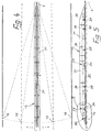
- the guide threshold line 2, 3, 13, 19, 20 used in the traffic areas according to FIGS. 1 to 3 is shown in more detail in FIGS. 4 and 5. It is composed of several guide thresholds 31, which are explained in more detail with reference to FIG. Take the guide threshold line 13 of FIG. 2 as an example.
- the guide sill strand 13 can be pivoted about a vertical axis of rotation 4, while at the other end the guide sill strand 13 is provided with a tensioning and locking unit 32, which enables the guide sill strand 13 between the axis of rotation 4 and a fixed point 14-18 embedded in the floor and to lock the position.
- FIG. 5 also shows that a plurality of non-driven rollers 35 are provided in the longitudinal direction of the guide sleeper line 13, but can be displaced vertically by lifting devices 36.
- the lifting devices 36 can be formed by pneumatically actuated cylinders.
- the guide sleeper strand 13 lies directly on the floor 37, while the rollers 34, 35 are extended downward for displacement, and the frictional contact of the guide sleeper strand 13 with the floor 37 is thereby eliminated.
- FIGS. 6 to 9 show an electric motor drive 33.
- Each drive 33 comprises two electric motors 38, which drive on rollers 34 via gears 39.
- pneumatically actuated lifting cylinders 40 are arranged between the electric motors 38, which extend the rollers 34 downward out of the guide sleeper strand 13 and can thereby lift it off the floor 37, so that it only rests on the rollers 34 and 35.
- the tensioning and locking unit 32 which serves to tension a guide threshold strand 2, 3, 13, 19, 20 in the longitudinal direction and its respective local locking in the fixed points 5-8, 14-18 and 21-30 is shown in FIGS. 6, 10 and 11 remove. It is again explained using the guide threshold line 13 and the fixed point 14.
- the tensioning and locking unit 32 initially comprises a guide body 41 which can be displaced in a positively guided manner in a groove 42 of a base plate 43 fastened in the guide sleeper line 13.
- the guide body 41 laterally carries a nut 44 which is penetrated by a threaded spindle 45.
- the spindle ends are rotatably supported in two bearing blocks 46 which are fastened on the base plate 43.
- the threaded spindle 45 is driven by an electric motor 47 via a gear 48 and a coupling 49.
- the guide body 41 is consequently displaced in one or the other direction in the groove 42 of the base plate 43.
- a spherical locking element 50 can be displaced vertically in the guide body 41. The displacement takes place with the aid of a pneumatically actuated cylinder 51 which is fastened on the guide body 41. It can also be seen that a sensor 52 is arranged on the locking element 50.
- the guide threshold strand 13 has just been displaced and the sensor 52 of the locking element 50 is oriented over the fixed point 14 for the purpose of determining the exact position.
- a cover plate 55 which is vertically displaceable against an elastic restoring force 54 is provided on the fixed point 14 which has a clamping housing 53 embedded in the floor 37.
- the locking element 50 is moved downward by acting on the pneumatic cylinder 51, whereby the cover plate 55 is moved downward against the restoring force of the spring 54.
- the locking element 50 is at a height at which it is completely immersed in the clamping housing 53 ( Figure 11, left half), the lifting movement is ended.
- the tensioning unit 32 is now activated, which shifts the locking element 50 transversely in the tensioning housing 53 until it is supported on the tensioning housing 53 in such a way that the guide sleeper strand 13 is tensioned in the longitudinal direction.
- the degree of tension is monitored by a force sensor 56 (FIG. 10), which is assigned to the gear 48.
- the guide sill strand 13 is first relaxed in the longitudinal direction until the locking element 50 lies exactly below the opening 57 which receives the cover plate 55.
- the pneumatic cylinder 51 is now acted upon and the locking element 50 is moved upward out of the clamping housing 53.
- the cover plate 55 follows the locking element 50 into a position (right half of FIG. 11) in which the cover plate 55 can again be passed over by the rolling traffic without problems.
- the guide sleeper line 13 can be shifted about the axis of rotation 4 by first extending the rollers 34, 35 and then activating the electric motors 38.
- the guide threshold strand 13 now rolls into the intended pivot position and is locked there in the manner described above in one of the fixed points 15-18.
- the guide threshold line 13 has, in accordance with FIG. cross-sectionally trapezoidal, internally stiffened guide sleepers 31 with lateral drive-on legs 58 and coupling tabs 59 at the end.
- the guide sleepers 31 are stiffened by runners 60 which are U-shaped in cross section and open at the top (FIGS. 6 and 8).
- the runners 60 extend from areas below the slightly inclined drive-on leg 58 to approximately half the height of the guide thresholds 31.
- the end faces of the vertical runner legs are on the inner contour of the drive-on leg 58 and the flat side surfaces 62 that end on the drive-on leg 58 with a curved transition section 61 the guide thresholds 31 are positively adapted. They are also welded to the drive-on legs 58, the transition sections 61 and the side surfaces 62.
- guide sleepers 31 there are provided guide rails 63 which are open at the bottom and have a trapezoidal cross section, which are put over the guide sleepers 31 and are detachably coupled to them by screw connections 64.
- the angle of inclination of the flat side surfaces 62 of the guide sleepers 31 and 66 of the guide rails 63 with respect to the vertical is approximately 10 °.
- the guide bars 63 also have coupling tabs 65 for mutual connection.
Landscapes
- Engineering & Computer Science (AREA)
- Architecture (AREA)
- Civil Engineering (AREA)
- Structural Engineering (AREA)
- Road Signs Or Road Markings (AREA)
- Refuge Islands, Traffic Blockers, Or Guard Fence (AREA)
- Glass Compositions (AREA)
Abstract
Description
Die Erfindung betrifft einen Leitschwellenstrang gemäß den Merkmalen im Oberbegriff des Anspruchs 1.The invention relates to a guide threshold line according to the features in the preamble of
Ein solcher Leitschwellenstrang zählt durch die US-PS 46 32 598 zum Stand der Technik. Dieser Leitschwellenstrang kann mit Hilfe von elektromotorisch angetriebenen Laufrollen ausschließlich in Querrichtung verlagert werden. Auf diese Weise ist es möglich, bei mehrspurigen Verkehrswegen beiden Fahrtrichtungen dieselbe Anzahl von Fahrspuren oder in Abhängigkeit von dem Verkehrsaufkommen eine unterschiedliche Anzahl von Verkehrsspuren-zuzuordnen. Dies ist beispielsweise im morgendlichen oder abendlichen Berufsverkehr bei Ein- und Ausfallstraßen von Großstädten von Vorteil.Such a threshold line is part of the prior art through US Pat. No. 4,632,598. This guide sleeper string can only be moved in the transverse direction with the help of rollers driven by an electric motor. In this way it is possible to assign the same number of lanes to two directions of travel in the case of multi-lane traffic routes or, depending on the traffic volume, to assign a different number of traffic lanes. This is an advantage, for example, in the morning or evening rush hour traffic on major and minor roads in major cities.
Ferner ist es im Umfang der US-PS 44 74 503 bekannt, einen gelenkigen Leitschwellenstrang mit Hilfe eines speziellen Verlegewagens quer zu sich selber zu verlagern, um auf diese Weise durch eine Veränderung der Anzahl der Fahrspuren ebenfalls dem jeweiligen Verkehrsaufkommen gerecht werden zu können.Furthermore, it is known in the scope of US-
Nun gibt es aber Verkehrkehrsleitprobleme, insbesondere vor und nach Tunnelröhren oder im Bereich von Mautstellen auf mehrspurigen Verkehrswegen (Autobahnen), bei denen es nicht auf die Bereitstellung von mehr Fahrspuren ankommt, um den rollenden Verkehr möglichst flüssig zu halten, sondern wo mehrere Fahrspuren auf eine geringere Anzahl zusammengeführt oder zumindest eine Fahrspur fächerförmig auf mehrere Fahrspuren erweitert werden sollen. Dies ist z.B. bei der Sperrung von Tunnelröhren, bei der Nichtbesetzung von Kassenhäuschen bei Mautstellen oder auch bei der Sperrung bestimmter Fahrwege notwendig. In diesen Fällen war es bislang üblich, daß die Leitschwellenstränge so manuell aus ihrer Längsrichtung verlagert wurden, daß der beispielsweise auf zwei Fahrspuren anrollende Verkehr statt in zwei Tunnelröhren nur in eine Tunnelröhre gelenkt oder von zwei Tunnelröhren in eine abführende Fahrspur überführt wird. Ähnlich ging man auch bei der Sperrung von Fahrwegen vor, wo dann an bestimmten Stellen eine Fahrwegbegrenzung geöffnet wird und der Verkehr von der einen Seite der Fahrwegbegrenzung auf die andere Seite gelenkt wird.Now there are traffic management problems, especially before and after tunnels or in the area of toll gates on multi-lane traffic routes (motorways), where it is not important to provide more lanes to keep rolling traffic as smooth as possible, but where several lanes in one a smaller number should be merged or at least one lane should be expanded into several lanes in a fan shape. This is e.g. necessary when tunnel tubes are blocked, when the ticket booths are not occupied at toll booths or when certain routes are blocked. In these cases, it was previously common for the guide sleeper strands to be shifted manually from their longitudinal direction in such a way that the traffic that, for example, rolled into two lanes was only directed into a tunnel tube instead of two tunnel tubes or was transferred from two tunnel tubes into a lane. A similar procedure was followed for the blocking of routes, where a route limitation is then opened at certain points and the traffic is directed from one side of the route limitation to the other side.
Der mit dem Umsetzen von Leitschwellensträngen bzw. der zusätzlichen Installierung verbundene zeitliche und personelle Aufwand ist hoch. Außerdem sind Gefährdungen der Personen, die das Umsetzen vornehmen, nicht ausgeschlossen, da die Arbeiten zumindest in der Nähe von weiterhin rollendem Verkehr durchgeführt werden müssen.The expenditure of time and personnel associated with the implementation of control threshold lines or the additional installation is high. In addition, hazards to the people carrying out the implementation are not excluded, since the work must be carried out at least in the vicinity of traffic that continues to move.
Der Erfindung liegt ausgehend vom Stand der Technik die Aufgabe zugrunde, einen Leitschwellenstrang zu schaffen, der es ohne Gefährdung von Monteuren kurzfristig erlaubt, Verkehrsströme aus vorgegebenen Fahrspuren an bestimmten Verkehrsbereichen seitlich abzulenken, ohne daß es hierzu manueller Tätigkeiten bedarf.Based on the prior art, the invention is based on the object of creating a guide threshold line, which, without endangering mechanics, allows traffic flows to be laterally diverted from specified lanes in certain traffic areas without the need for manual work.
Die Lösung dieser Aufgabe besteht nach der Erfindung in den im kennzeichnenden Teil des Anspruchs 1 aufgeführten Merkmalen.This object is achieved according to the invention in the features listed in the characterizing part of
Der erfindungsgemäße Leitschwellenstrang ist grundsätzlich zwischen zwei Fixpunkten in seiner Längsrichtung verspannt. Dazu ist an mindestens einem Ende des Leitschwellenstrangs eine Spann- und Arretiereinheit in den Leitschwellenstrang eingegliedert. Diese Spann- und Arretiereinheit ist so ausgebildet, daß sie einerseits die Verspannung des Leitschwellenstrangs zwischen den beiden Fixpunkten übernimmt, andererseits jedoch auch die bodenseitige Arretierung des Leitschwellenstrangs an einem Fixpunkt gewährleistet, der in den Boden eingelassen und von dem rollenden Verkehr überfahrbar ist. Soll mithin aufgrund der örtlichen Gegebenheiten der Leitschwellenstrang im Winkel verschwenkt werden, genügt es, wenn an einem Ende eine Spann- und Arretiereinrichtung angeordnet ist und sich am anderen Ende des Leitschwellenstrangs eine ortsfeste Drehachse befindet. Für das Schwenken des Leitschwellenstrangs wird dann mit Hilfe der Spann- und Arretiereinheit die Längsverspannung zwischen den Fixpunkten aufgehoben, die Arretierung des Leitschwellenstrangs am bodenseitigen Fixpunkt gelöst und der Leitschwellenstrang um die Drehachse motorisch rollend so weit geschwenkt, bis daß der vorgesehene nächste bodenseitige, von dem rollenden Verkehr überfahrbare Fixpunkt erreicht ist. Hier wird dann der Leitschwellenstrang wieder am Boden arretiert und in Längsrichtung verspannt.The guide threshold strand according to the invention is basically clamped between two fixed points in its longitudinal direction. For this purpose, a tensioning and locking unit is incorporated into the guide threshold line at at least one end of the guide line. This tensioning and locking unit is designed so that it takes over the tensioning of the guide sill strand between the two fixed points on the one hand, but on the other hand also ensures the bottom-side locking of the guide sill strand at a fixed point that is let into the ground and can be run over by rolling traffic. If, therefore, the guiding sleeper strand is to be pivoted at an angle due to the local conditions, it is sufficient if a tensioning and locking device is arranged at one end and a stationary axis of rotation is located at the other end of the guiding sleeper strand. For the pivoting of the guide sill strand, the longitudinal tension between the fixed points is then released with the help of the tensioning and locking unit, the locking of the guide sill strand at the base-side fixed point is released and the guide sill strand is pivoted so that it rolls by motor around the axis of rotation until the intended next floor-side, by which Rolling traffic overrun fixed point is reached. Here, the guide threshold line is then locked again on the floor and braced in the longitudinal direction.
Die Ausbildung des Leitschwellenstrangs mit einer ortsfesten Drehachse an einem Ende und mit einer Spann- und Arretiereinheit am anderen Ende kann beispielsweise dort mit Vorteil installiert werden, wo der Verkehr von einer Fahrspur seitlich auf eine andere Fahrspur abgelenkt werden muß. Dies kann vor oder nach Tunnelröhren, vor oder nach Mautstellen oder auch auf mehrspurigen Fahrwegen der Fall sein, wo gezielt der Verkehr von der einen auf die andere Seite einer ansonsten fest installierten Fahrwegbegrenzung überführt werden muß. Bei diesem Einzelfall können auch zwei Leitschwellenstränge gewissermaßen die Flügel eines Tors bilden, das in der geschlossenen Fahrwegbegrenzung geöffnet wird. Der eine Leitschwellenstrang wird dann in die eine und der andere Leitschwellenstrang in die andere Richtung verschwenkt und dort neu fixiert.The formation of the guide sleeper line with a fixed axis of rotation at one end and with a tensioning and locking unit at the other end can, for example, be installed advantageously where the traffic has to be deflected laterally from one lane to another lane. This can be the case before or after tunnel tubes, before or after tollbooths or on multi-lane roads where the traffic must be transferred from one side to the other of an otherwise permanently installed roadway boundary. In this individual case, two guide threshold strands can form the wings of a gate that is opened in the closed guideway boundary. The one guiding threshold line is then pivoted in one direction and the other guiding threshold line in the other direction and re-fixed there.
Die Erfindung eröffnet aber auch die Möglichkeit, an beiden Enden eines Leitschwellenstrangs Spann- und Arretiereinheiten vorzusehen, so daß dann auch die Fixpunkte an beiden Enden des Leitschwellenstrangs von dem rollenden Verkehr überfahrbar sein müssen, wenn der Leitschwellenstrang parallel zu sich selbst in eine andere Einsatzposition verlagert wird.However, the invention also opens up the possibility of providing tensioning and locking units at both ends of a guide threshold line, so that the fixed points on both ends of the guide line must then be able to be driven over by the rolling traffic if the guide line moves parallel to itself into another position of use becomes.
Selbstverständlich ist es im Rahmen der Erfindung auch möglich, zwei oder mehrere verlagerbare Leitschwellenstränge begrenzter Länge in Längsrichtung hintereinander vorzusehen.Of course, it is also possible within the scope of the invention to provide two or more displaceable guide threshold strands of limited length in the longitudinal direction one behind the other.
Wieviele Laufrollen ein Leitschwellenstrang aufweist, und wieviele von den Laufrollen elektromotorisch angetrieben sind, hängt von dem Einsatzort und den jeweiligen örtlichen Gegebenheiten ab.How many rollers a guide threshold line has and how many of the rollers are driven by an electric motor depends on the place of use and the respective local conditions.
Die Fixpunkte sind so ausgebildet, daß sie nicht nur eine ordnungsgemäße Verspannung eines Leitschwellenstrangs in Längsrichtung und seine örtliche Arretierung sicherstellen, sondern auch zu allen Jahreszeiten unter sämtlichen Witterungsbedingungen ihre Funktion im Zusammenwirken mit den Spann- und Arretiereinheiten gewährleisten.The fixed points are designed in such a way that they not only ensure proper tensioning of a guide threshold strand Ensure the longitudinal direction and its local locking, but also ensure their function in cooperation with the tensioning and locking units in all seasons under all weather conditions.
Das gemäß Anspruch 2 einer Spann- und Arretiereinheit zugeordnete Verriegelungselement bildet im Zusammenwirken mit einem von dem rollenden Verkehr überfahrbaren Fixpunkt gewissermaßen ein Widerlager, das zusammen mit dem Fixpunkt am anderen Ende die Verspannung des Leitschwellenstrangs in Längsrichtung und seine örtliche Verriegelung sicherstellt.The locking element assigned according to
Entsprechend einer vorteilhaften Weiterbildung der Erfindung ist gemäß Anspruch 3 das Verriegelungselement an einem in Längsrichtung des Leitschwellenstrangs zwangsläufig beweglichen Führungskörper vorgesehen, der zugleich eine Hubeinrichtung für das Verriegelungselement trägt. Der Führungskörper kann beispielsweise an einer fest mit dem Leitschwellenstrang verbundenen Grundplatte entlang zwangsgeführt sein, und zwar mit Hilfe einer von einem Elektromotor drehbaren Gewindespindel. Denkbar sind aber auch pneumatisch oder hydraulisch beaufschlagbare Zylinder, welche den Führungskörper in Längsrichtung des Leitschwellenstrangs verlagern. Die von dem Führungskörper getragene Hubeinrichtung kann elektromotorisch, pneumatisch oder hydraulisch ausgebildet sein. Sie ist in der Lage, das Verriegelungselement mit einem Fixpunkt zu kuppeln und zu entkuppeln.According to an advantageous development of the invention, according to
Desweiteren ist es gemäß den Merkmalen des Anspruchs 4 von Vorteil, daß die von dem rollenden Verkehr überfahrbaren Fixpunkte ausschließlich durch ein Verriegelungselement beeinflußbar sind. Zu diesem Zweck weist jeder Fixpunkt eine Deckelplatte als Bestandteil eines fest im Boden verankerten Spanngehäuses auf. Diese Deckelplatte ist in Schließrichtung des Spanngehäuses so federbelastet, daß der rollende Verkehr den Fixpunkt problemlos überfahren und auch auf ihm stehen kann. Soll ein Leitschwellenstrang am Boden arretiert werden, so wird das Verriegelungselement mit Hilfe der Hubeinrichtung vertikal nach unten bewegt. Hierbei wird die Deckelplatte durch das Verriegelungselement gegen die Rückstellkraft verlagert. Anschließend erfolgt eine Längsverlagerung des Führungskörpers der Spann- und Arretiereinheit mit dem Ergebnis, daß dann der Leitschwellenstrang zwischen diesem Fixpunkt und dem Fixpunkt am anderen Ende (feste Drehachse oder vom Verkehr überrollbarer Fixpunkt) verspannt ist.Furthermore, according to the features of
Damit beim Verlagern eines Leitschwellenstrangs und Erreichen eines neuen vom Verkehr überfahrbaren Fixpunkts die Ver- und Entriegelungsstellungen auch einwandfrei definiert sind, wird entsprechend Anspruch 5 dem Verriegelungselement ein mit den Deckelplatten zusammenwirkender Sensor zugeordnet. Erst wenn über diesen Sensor die einwandfreie Verriegelungsposition ermittelt worden ist, erfolgt eine Aktivierung der Spann- und Arretiereinheit.So that the locking and unlocking positions are also correctly defined when moving a guide threshold line and reaching a new fixed point that can be run over by traffic, a sensor interacting with the cover plates is assigned to the locking element. The tensioning and locking unit is only activated when the correct locking position has been determined via this sensor.
Die Merkmale des Anspruchs 6 erlauben in bevorzugter Ausgestaltung der Erfindung die Fernsteuerbarkeit aller beweglichen Einrichtungen. Die Fernsteuerung kann von einem zentralen Leitstand aus erfolgen. Desweiteren können die Einrichtungen aber auch an einen Rechner angeschlossen sein. Über das in den Rechner eingegebene Programm ist es dann möglich, durch entsprechenden Knopfdruck den jeweiligen Leitschwellenstrang in der gewünschten Weise zu verlagern.In a preferred embodiment of the invention, the features of
In Anbetracht des Sachverhalts, daß es sich bei dem erfindungsgemäßen Leitschwellenstrang um einen solchen begrenzter Länge handelt, beispielsweise 50 m bis 100 m lang, und stets eine sichere Verspannung zwischen den endseitigen Fixpunkten gewährleistet sein muß, erweist sich eine entsprechend stabile Gestaltung des Leitschwellenstrangs gemäß den Merkmalen des Anspruchs 7 als besonders vorteilhaft.In view of the fact that the guide threshold line according to the invention is of such a limited length, for example 50 m to 100 m long, and a secure bracing between the end fixed points must always be guaranteed, a correspondingly stable design of the guide threshold strand according to the features of
Die Erfindung ist nachfolgend anhand von in den Zeichnungen dargestellten Ausführungsbeispielen näher erläutert. Es zeigen:
Figuren 1 bis 3- in schematischer Draufsicht verschiedene Verkehrsbereiche mit verlagerbaren Leitschwellensträngen;
Figur 4- den Verkehrsbereich der
Figur 2 in detaillierterer Darstellung; Figur 5- eine Seitenansicht des Leitschwellenstrangs gemäß
Figur 4; Figur 6- den Ausschnitt VI der
Figur 5 in vergrößertem Maßstab, teilweise im Vertikalschnitt; Figur 7- den Ausschnitt VII der
Figur 6 in nochmals vergrößertem Maßstab; Figur 8- einen Vertikalschnitt durch die Darstellung der
Figur 7 entlang der Linie VIII-VIII; Figur 9- einen Horizontalschnitt durch die Darstellung der
Figur 8 entlang der Linie IX-IX; Figur 10- in vergrößerter Darstellung eine Draufsicht auf den Schnitt XI der
Figur 6; Figur 11- den Schnitt
XI der Figur 7 in 180° Versetzung in vergrößerter Darstellung in zwei verschiedenen Betriebspositionen und Figur 12- in perspektivischer Darstellung einen Abschnitt des Leitschwellenstrangs der Figuren 4
und 5.
- Figures 1 to 3
- a schematic top view of different traffic areas with relocatable guide threshold lines;
- Figure 4
- the traffic area of Figure 2 in more detail;
- Figure 5
- a side view of the guide threshold strand according to Figure 4;
- Figure 6
- the section VI of Figure 5 on an enlarged scale, partially in vertical section;
- Figure 7
- the section VII of Figure 6 on a further enlarged scale;
- Figure 8
- a vertical section through the representation of Figure 7 along the line VIII-VIII;
- Figure 9
- a horizontal section through the representation of Figure 8 along the line IX-IX;
- Figure 10
- in an enlarged view a plan view of the section XI of Figure 6;
- Figure 11
- the section XI of Figure 7 in 180 ° offset in an enlarged view in two different operating positions and
- Figure 12
- a perspective view of a section of the guide threshold strand of Figures 4 and 5.
Mit 1 ist in der Figur 1 eine Fahrwegbegrenzung bezeichnet, die zwei Fahrwege FW1, FW2 voneinander trennt. Im Verlauf dieser Fahrwegbegrenzung 1 sind zwei Leitschwellenstränge 2, 3 eingegliedert, die um ortsfeste vertikale Drehachsen 4 in Querrichtung der Fahrwegbegrenzung 1 verschwenkbar sind. Die Leitschwellenstränge 2, 3 sind in der gestreckten Betriebsposition (geschlossene Linienführung) zwischen den Drehachsen 4 und vom rollenden Verkehr überfahrbaren Fixpunkten 5 in Längsrichtung verspannt und lagearretiert.1 in FIG. 1 denotes a travel path boundary that separates two travel paths FW1, FW2 from one another. In the course of this
Beim Ausführungsbeispiel sind die Leitschwellenstränge 2, 3 gemäß den Pfeilen PF so um die Drehachsen 4 verschwenkt und an den Fixpunkten 6 arretiert (strichpunktierte Linienführung), daß der Verkehr von der Fahrspur FS1 des Fahrwegs FW1 über den dann offenen Bereich zwischen den beiden Leitschwellensträngen 2, 3 auf die Fahrspur FS2 des Fahrwegs FW2 überführt werden kann.In the exemplary embodiment, the
Selbstverständlich können die Leitschwellenstränge 2, 3 gemäß den Pfeilen PF1 auch in die jeweils andere Richtung verschwenkt werden (Strich-Punkt-Punkt-Linienführung), so daß dann der Verkehr von der Fahrspur FS1 des Fahrwegs FW1 auf die parallele Fahrspur FS3 und der Verkehr von der Fahrspur FS2 des Fahrwegs FW2 auf die parallele Fahrspur FS4 überführt werden kann. In diesem Fall sind die Leitschwellenstränge 2, 3 in den Fixpunkten 7 arretiert.Of course, the
Ferner können die Leitschwellenstränge 2, 3 über die gesamte Breite der Fahrwege FW1 und FW2 verschwenkt werden (Strich-Punkt-Punkt-Punkt-Linienführung). Sie werden dann in den Fixpunkten 8 arretiert. Auf diese Weise können bei Bedarf beide Fahrspuren FS1 und FS3 auf den parallelen Fahrweg FW2 gelenkt werden.In addition, the
In der Figur 2 ist in der Draufsicht ein Verkehrsbereich vor vier Tunnelröhren 9, 10, 11, 12 veranschaulicht. Die beiden Fahrwege FW1 und FW2 mit jeweils zwei Fahrspuren FS1, FS3 bzw. FS2, FS4 sind durch eine Fahrwegbegrenzung 1 voneinander getrennt. Im Verlauf dieser Fahrwegbegrenzung 1 ist ein Leitschwellenstrang 13 eingegliedert, der sich zwischen einer ortsfesten Drehachse 4 und einem vom rollenden Verkehr überfahrbaren Fixpunkt 14 erstreckt. Zwischen der Drehachse 4 und dem Fixpunkt 14 ist der Leitschwellenstrang 13 in Längsrichtung verspannt. Desweiteren ist der Leitschwellenstrang 13 am Fixpunkt 14 lagearretiert.FIG. 2 shows a top view of a traffic area in front of four
Je nach den örtlichen Gegebenheiten, beispielsweise bei Sperrung einer der Tunnelröhren 9-12, kann es erforderlich werden, den Verkehrsstrom entsprechend zu lenken. In diesem Fall wird folglich der Leitschwellenstrang 13 entsprechend den Pfeilen PF2-PF5 in eine der vier Ausweichpositionen um die Drehachse 4 verlagert (strichpunktierte Linienführung) und hier über die dort vorgesehenen Fixpunkte 15-18 verankert.Depending on the local conditions, for example when one of the tunnel tubes 9-12 is blocked, it may be necessary to control the traffic flow accordingly. In this case, the
Vorstellbar ist es bei der Ausführungsform der Figur 2 auch, daß in der Normalposition zwei Leitschwellenstränge 13, 19 unmittelbar nebeneinander in Längsrichtung hinter der Fahrwegbegrenzung 1 angeordnet sind. Der Leitschwellenstrang 13 kann dann in den in die Tunnelröhren 9, 10 führenden Fahrweg FW1 und der andere Leitschwellenstrang 19 in den aus den Tunnelröhren 11, 12 führenden Fahrweg FW2 verschwenkt werden.It is also conceivable in the embodiment of FIG. 2 that, in the normal position, two
Die Figur 3 zeigt in der Draufsicht eine Fahrwegbegrenzung 1 zwischen zwei Fahrwegen FW1, FW2 und einen in diese Fahrwegbegrenzung 1 integrierten Leitschwellenstrang 20, der gemäß den Pfeilen PF6 parallel zu sich selbst verlagerbar ist. Der Leitschwellenstrang 20 ist zwischen zwei vom rollenden Verkehr überfahrbaren Fixpunkten 21, 22 fest verspannt und an den Fixpunkten 21, 22 arretiert. Auch in der quer verlagerten Betriebsposition (strichpunktierte Linienführung) ist der Leitschwellenstrang 20 zwischen zwei vom rollenden Verkehr überfahrbaren Fixpunkten 23, 24 verspannt und in diesen Fixpunkten 23, 24 lagearretiert.FIG. 3 shows a top view of a
Der Leitschwellenstrang 20 kann selbstverständlich gemäß den Pfeilen PF7, PF8 und PF9 auch an den Rand des Fahrwegs FW1, zwischen die beiden Fahrspuren FS2 und FS4 des Fahrwegs FW2 oder an den Rand des Fahrwegs FW2 verlagert werden. In diesen Betriebsstellungen wird der Leitschwellenstrang 20 dann in den Fixpunkten 25, 26 bzw. 27, 28 bzw. 29, 30 arretiert.According to the arrows PF7, PF8 and PF9, the
Der in den Verkehrsbereichen gemäß den Figuren 1 bis 3 zur Anwendung kommende Leitschwellenstrang 2, 3, 13, 19, 20 ist in den Figuren 4 und 5 konstruktiv näher dargestellt. Er setzt sich aus mehreren anhand der Figur 12 noch eingehender erläuterten Leitschwellen 31 zusammen. Als Beispiel sei der Leitschwellenstrang 13 der Figur 2 angenommen.The
An einem Ende ist der Leitschwellenstrang 13 um eine vertikale Drehachse 4 verschwenkbar, während am anderen Ende der Leitschwellenstrang 13 mit einer Spann- und Arretiereinheit 32 versehen ist, die es ermöglicht, den Leitschwellenstrang 13 zwischen der Drehachse 4 und einem im Boden eingelassenen Fixpunkt 14-18 zu verspannen und lagezuarretieren.At one end, the
Ferner sind in Längsrichtung des Leitschwellenstrangs 13 elektromotorische Antriebe 33 eingegliedert, die vertikal verlagerbare Laufrollen 34 antreiben. Außerdem zeigt die Figur 5, daß in Längsrichtung des Leitschwellenstrangs 13 mehrere nicht angetriebene Laufrollen 35 vorgesehen sind, die jedoch durch Hubeinrichtungen 36 vertikal verlagerbar sind. Die Hubeinrichtungen 36 können durch pneumatisch beaufschlagbare Zylinder gebildet sein.Furthermore, 13
In der Einsatzposition liegt der Leitschwellenstrang 13 unmittelbar auf dem Boden 37, während zum Verlagern die Laufrollen 34, 35 nach unten ausgefahren werden und dadurch der Reibkontakt des Leitschwellenstrangs 13 mit dem Boden 37 aufgehoben wird.In the use position, the
Die Figuren 6 bis 9 zeigen einen elektromotorischen Antrieb 33. Jeder Antrieb 33 umfaßt zwei Elektromotoren 38, die über Getriebe 39 auf Laufrollen 34 abtreiben. Außerdem sind zwischen den Elektromotoren 38 pneumatisch betätigbare Hubzylinder 40 angeordnet, welche die Laufrollen 34 nach unten aus dem Leitschwellenstrang 13 ausfahren und ihn dadurch vom Boden 37 abheben können, so daß er nur noch auf den Laufrollen 34 und 35 ruht.FIGS. 6 to 9 show an
Die der Verspannung eines Leitschwellenstrangs 2, 3, 13, 19, 20 in Längsrichtung und seiner jeweiligen örtlichen Arretierung in den Fixpunkten 5-8, 14-18 und 21-30 dienende Spann- und Arretiereinheit 32 ist den Figuren 6, 10 und 11 zu entnehmen. Sie wird wiederum anhand des Leitschwellenstrangs 13 und des Fixpunkts 14 erläutert.The tensioning and locking
Die Spann- und Arretiereinheit 32 umfaßt zunächst einen Führungskörper 41, der in einer Nute 42 einer im Leitschwellenstrang 13 befestigten Grundplatte 43 zwangsgeführt verlagerbar ist. Der Führungskörper 41 trägt seitlich eine Mutter 44, die von einer Gewindespindel 45 durchsetzt ist. Die Spindelenden sind in zwei Lagerböcken 46 drehbar gelagert, welche auf der Grundplatte 43 befestigt sind. Angetrieben wird die Gewindespindel 45 von einem Elektromotor 47 über ein Getriebe 48 und eine Kupplung 49. Je nach Drehrichtung der Gewindespindel 45 wird folglich der Führungskörper 41 in die eine oder andere Richtung in der Nute 42 der Grundplatte 43 verlagert.The tensioning and locking
Im Führungskörper 41 ist ein kugelförmiges Verriegelungselement 50 vertikal verlagerbar. Die Verlagerung erfolgt mit Hilfe eines pneumatisch beaufschlagbaren Zylinders 51, der auf dem Führungskörper 41 befestigt ist. Außerdem ist zu erkennen, daß am Verriegelungselement 50 ein Sensor 52 angeordnet ist.A
In der in den Figuren 4 bis 6 und 11 veranschaulichten Position ist der Leitschwellenstrang 13 gerade verlagert worden und der Sensor 52 des Verriegelungselements 50 orientiert sich über dem Fixpunkt 14 zwecks genauer Lagebestimmung. Hierzu ist an dem ein in den Boden 37 eingelassenes Spanngehäuse 53 aufweisenden Fixpunkt 14 eine gegen eine elastische Rückstellkraft 54 vertikal verlagerbare Deckelplatte 55 vorgesehen.In the position illustrated in FIGS. 4 to 6 and 11, the
Hat der Sensor 52 im Zusammenwirken mit der Deckelplatte 55 die genaue Lage des Fixpunkts 14 ermittelt, wird durch Beaufschlagung des Pneumatikzylinders 51 das Verriegelungselement 50 abwärts bewegt, wodurch die Deckelplatte 55 gegen die Rückstellkraft der Feder 54 abwärts bewegt wird. Befindet sich das Verriegelungselement 50 in einer Höhe, in welcher es völlig in das Spanngehäuse 53 eingetaucht ist (Figur 11, linke Hälfte), wird die Hubbewegung beendet. Dafür wird nunmehr die Spanneinheit 32 aktiviert, welche das Verriegelungselement 50 quer im Spanngehäuse 53 verlagert, bis es sich am Spanngehäuse 53 so abstützt, daß der Leitschwellenstrang 13 in Längsrichtung verspannt wird. Der Grad der Verspannung wird durch einen Kraftsensor 56 überwacht (Figur 10), der dem Getriebe 48 zugeordnet ist.If the
Soll die Lage des Leitschwellenstrangs 13 gemäß Figur 4 aufgehoben werden, so erfolgt zunächst eine Entspannung des Leitschwellenstrangs 13 in Längsrichtung, bis daß das Verriegelungselement 50 exakt unterhalb der die Deckelplatte 55 aufnehmenden Öffnung 57 liegt. Nunmehr wird der Pneumatikzylinder 51 beaufschlagt und das Verriegelungselement 50 nach oben aus dem Spanngehäuse 53 bewegt. Die Deckelplatte 55 folgt dem Verriegelungselement 50 bis in eine Stellung (rechte Hälfte der Figur 11), in der die Deckelplatte 55 wieder einwandfrei von dem rollenden Verkehr überfahrbar ist.If the position of the
Jetzt kann der Leitschwellenstrang 13 dadurch um die Drehachse 4 verlagert werden, daß zunächst die Laufrollen 34, 35 ausgefahren und dann die Elektromotoren 38 aktiviert werden. Der Leitschwellenstrang 13 rollt nun in die vorgesehene Schwenkstellung und wird dort in der vorstehend beschriebenen Weise in einem der Fixpunkte 15-18 arretiert.Now the
Sämtliche Bewegungen sind ferngesteuert und/oder in einem Rechner programmiert, so daß kein manueller Aufwand für die Verlagerung, Verspannung und Arretierung eines Leitschwellenstrangs 13 erforderlich ist.All movements are remotely controlled and / or programmed in a computer, so that no manual effort for the displacement, tensioning and locking of a
Der Leitschwellenstrang 13 gemäß den Figuren 4 und 5 besitzt entsprechend Figur 12 mehrere schußweise lösbar aneinandergesetzte, im Querschnitt trapezförmige, innen ausgesteifte Leitschwellen 31 mit seitlichen Auffahrschenkeln 58 und endseitigen Kupplungslaschen 59. Die Leitschwellen 31 sind durch im Querschnitt U-förmige, nach oben offene Kufen 60 ausgesteift (Figuren 6 und 8). Die Kufen 60 erstrecken sich aus Bereichen unterhalb der leicht geneigten Auffahrschenkel 58 bis etwa zur halben Höhe der Leitschwellen 31. Die Stirnseiten der vertikalen Kufenschenkel sind an die Innenkontur der Auffahrschenkel 58 sowie der sich an die Auffahrschenkel 58 mit einem gekrümmten Übergangsabschnitt 61 abschließenden ebenen Seitenflächen 62 der Leitschwellen 31 formschlüssig angepaßt. Außerdem sind sie mit den Auffahrschenkeln 58, den Übergangsabschnitten 61 sowie den Seitenflächen 62 verschweißt.The
Oberhalb der Leitschwellen 31 sind als nach unten offene, im Querschnitt trapezförmige Hauben ausgebildete Leitholme 63 vorgesehen, die über die Leitschwellen 31 gestülpt und mit diesen durch Schraubverbindungen 64 lösbar gekuppelt sind. Der Neigungswinkel der ebenen Seitenflächen 62 der Leitschwellen 31 sowie 66 der Leitholme 63 gegenüber der Vertikalen beträgt etwa 10°. Auch die Leitholme 63 besitzen Kupplungslaschen 65 zur gegenseitigen Verbindung.Above the
- 11
- - Fahrwegbegrenzung- Travel path limitation
- 22nd
- - Leitschwellenstrang- Guardrail line
- 33rd
- - Leitschwellenstrang- Guardrail line
- 44th
- - Drehachsen- axes of rotation
- 55
- - Fixpunkt- Fixed point
- 66
- - Fixpunkt- Fixed point
- 77
- - Fixpunkt- Fixed point
- 88th
- - Fixpunkt- Fixed point
- 99
- - Tunnelröhre- tunnel tube
- 1010th
- - Tunnelröhre- tunnel tube
- 1111
- - Tunnelröhre- tunnel tube
- 1212th
- - Tunnelröhre- tunnel tube
- 1313
- - Leitschwellenstrang- Guardrail line
- 1414
- - Fixpunkt- Fixed point
- 1515
- - Fixpunkt- Fixed point
- 1616
- - Fixpunkt- Fixed point
- 1717th
- - Fixpunkt- Fixed point
- 1818th
- - Fixpunkt- Fixed point
- 1919th
- - Leitschwellenstrang- Guardrail line
- 2020th
- - Leitschwellenstrang- Guardrail line
- 2121
- - Fixpunkt- Fixed point
- 2222
- - Fixpunkt- Fixed point
- 2323
- - Fixpunkt- Fixed point
- 2424th
- - Fixpunkt- Fixed point
- 2525th
- - Fixpunkt- Fixed point
- 2626
- - Fixpunkt- Fixed point
- 2727
- - Fixpunkt- Fixed point
- 2828
- - Fixpunkt- Fixed point
- 2929
- - Fixpunkt- Fixed point
- 3030th
- - Fixpunkt- Fixed point
- 3131
- - Leitschwellen- Guiding thresholds
- 3232
- - Spann- und Arretiereinheit- Tensioning and locking unit
- 3333
- - Elektroantrieb- electric drive
- 3434
- - Laufrollen- casters
- 3535
- - Laufrollen- casters
- 3636
- - Hubeinrichtungen- lifting devices
- 3737
- - Boden- Ground
- 3838
- - Elektromotoren- electric motors
- 3939
- - Getriebe- Transmission
- 4040
- - Hubzylinder- lifting cylinder
- 4141
- - Führungskörper- guide body
- 4242
- - Nute- Groove
- 4343
- - Grundplatte- base plate
- 4444
- - Mutter- Mother
- 4545
- - Gewindespindel- threaded spindle
- 4646
- - Lagerböcke- pillow blocks
- 4747
- - Elektromotor- electric motor
- 4848
- - Getriebe- Transmission
- 4949
- - Kupplung- clutch
- 5050
- - Verriegelungselement- locking element
- 5151
- - Zylinder- cylinder
- 5252
- - Sensor- sensor
- 5353
- - Spanngehäuse- clamping housing
- 5454
- - Rückstellkraft- restoring force
- 5555
- - Deckelplatte- cover plate
- 5656
- - Kraftsensor- force sensor
- 5757
- - Öffnung f. 55- opening f. 55
- 5858
- - Auffahrschenkel- Ascending leg
- 5959
- - Kupplungslaschen- Coupling tabs
- 6060
- - Kufen- runners
- 6161
- - Übergangsabschnitt- Transitional section
- 6262
- - Seitenflächen v. 31- side surfaces v. 31
- 6363
- - Leitholme- Guide rails
- 6464
- - Schraubverbindungen- screw connections
- 6565
- - Kupplungslaschen- Coupling tabs
- 6666
- - Seitenflächen v. 63- side surfaces v. 63
- FW1FW1
- - Fahrweg- road
- FW2FW2
- - Fahrweg- road
- FS1FS1
- - Fahrspur v. FW1- lane v. FW1
- FS2FS2
- - Fahrspur v. FW2- lane v. FW2
- FS3FS3
- - Fahrspur v. FW1- lane v. FW1
- FS4FS4
- - Fahrspur v. FW2- lane v. FW2
- PFPF
- - Pfeile- arrows
- PF1PF1
- - Pfeile- arrows
- PF2PF2
- - Pfeile- arrows
- PF3PF3
- - Pfeile- arrows
- PF4PF4
- - Pfeile- arrows
- PF5PF5
- - Pfeile- arrows
- PF6PF6
- - Pfeile- arrows
- PF7PF7
- - Pfeile- arrows
- PF8PF8
- - Pfeile- arrows
- PF9PF9
- - Pfeile- arrows
Claims (7)
wobei die Leitschwellen (31) durch im Querschnitt U-förmige, nach oben offene Kufen (60) ausgesteift sind, die sich aus Bereichen unterhalb der leicht geneigten Auffahrschenkel (58) bis etwa zu halben Höhe der Leitschwellen (31) erstrecken,
die Stirnseiten der vertikalen Kufenschenkel an die Innenkontur der Auffahrschenkel (58) sowie der sich an die Auffahrschenkel (58) mit einem gekrümmten Übergangsabschnitt (61) anschließenden ebenen Seitenflächen (62) der Leitschwellen (31) formschlüssig angepaßt und mit den Auffahrschenkeln (58), den Übergangsabschnitten (61) sowie den Seitenflächen (62) verschweißt sind,
die Leitholme (63) als nach unten offene, im Querschnitt trapezförmige Hauben ausgebildet, formschlüssig über die Leitschwellen (31) gestülpt und mit diesen durch Schraubverbindung (64) lösbar gekuppelt sind und
der Neigungswinkel der ebenen Seitenflächen (62, 66) der Leitschwellen (31) sowie der Leitholme (63) gegenüber der Vertikalen etwa 10° beträgt.Guide rail string according to one of claims 1 to 6, characterized in that it consists of a plurality of guide sleepers (31) with crosswise trapezoidal cross-section and internally stiffened guide sleepers (31) with lateral drive legs (58) and end coupling plates (59) and from above the guide sleepers (31 ) arranged and connected to the guide sleepers (31), also in sections placed against each other, guide rails (63) with end coupling tabs (65),
the guide sleepers (31) being stiffened by runners (60) which are U-shaped in cross section and open at the top and which extend from regions below the slightly inclined one Ramp legs (58) extend up to about half the height of the guide thresholds (31),
the end faces of the vertical runner legs are matched to the inner contour of the drive-on legs (58) and the flat side surfaces (62) of the guide sleepers (31) adjoining the drive-on legs (58) with a curved transition section (61) and with the drive-on legs (58), the transition sections (61) and the side surfaces (62) are welded,
the guide bars (63) are designed as hoods which are open at the bottom and trapezoidal in cross section, positively placed over the guide thresholds (31) and detachably coupled to them by screw connection (64) and
the angle of inclination of the flat side surfaces (62, 66) of the guide sleepers (31) and the guide rails (63) with respect to the vertical is approximately 10 °.
Applications Claiming Priority (2)
| Application Number | Priority Date | Filing Date | Title |
|---|---|---|---|
| DE4422050A DE4422050C2 (en) | 1994-06-27 | 1994-06-27 | Control threshold line |
| DE4422050 | 1994-06-27 |
Publications (2)
| Publication Number | Publication Date |
|---|---|
| EP0690176A1 true EP0690176A1 (en) | 1996-01-03 |
| EP0690176B1 EP0690176B1 (en) | 1998-08-12 |
Family
ID=6521359
Family Applications (1)
| Application Number | Title | Priority Date | Filing Date |
|---|---|---|---|
| EP95108372A Expired - Lifetime EP0690176B1 (en) | 1994-06-27 | 1995-06-01 | Chain of divider modules |
Country Status (5)
| Country | Link |
|---|---|
| EP (1) | EP0690176B1 (en) |
| AT (1) | ATE169706T1 (en) |
| DE (1) | DE4422050C2 (en) |
| ES (1) | ES2119275T3 (en) |
| TR (1) | TR199500760A2 (en) |
Cited By (5)
| Publication number | Priority date | Publication date | Assignee | Title |
|---|---|---|---|---|
| EP1124012A2 (en) * | 2000-02-01 | 2001-08-16 | elkosta security systems GmbH & Co. KG | Vehicle control system for lane changing |
| EP1124013A2 (en) * | 2000-02-01 | 2001-08-16 | elkosta security systems GmbH & Co. KG | Vehicle control system for lane changing |
| WO2008098465A1 (en) * | 2007-02-14 | 2008-08-21 | Guozhu Ji | A transversely moveable road barricade |
| EP2107164A3 (en) * | 2008-04-01 | 2012-09-26 | Heintzmann Sicherheitssysteme GmbH & Co. KG | Safety barrier on roadways |
| CN104532771A (en) * | 2014-11-28 | 2015-04-22 | 张灵杰 | Intelligent traffic control system with LED light bars and position sensors |
Families Citing this family (7)
| Publication number | Priority date | Publication date | Assignee | Title |
|---|---|---|---|---|
| DE10256199B4 (en) * | 2002-12-02 | 2004-11-18 | Linde, Albrecht von, Dr. | Device and method for changing the route of a vehicle racing track |
| EP1619312B1 (en) | 2004-07-19 | 2009-09-30 | Volkmann & Rossbach GmbH & Co. KG | Safety barrier passage |
| DE102005011382B4 (en) * | 2005-03-11 | 2007-01-11 | Volkmann & Rossbach Gmbh & Co. Kg | A vehicle restraint system for securing lanes in a passage area and a barrier element for a vehicle restraint system |
| DE102005059353B4 (en) * | 2005-12-09 | 2008-10-16 | Heintzmann Sicherheitssysteme Gmbh & Co. Kg | Safety device for limiting the road |
| DE102007029926A1 (en) | 2007-06-28 | 2009-01-02 | Volkmann & Rossbach Gmbh & Co. Kg | Vehicle restraint system for securing lanes with a passage area |
| CN104376722B (en) * | 2014-11-28 | 2015-07-01 | 温岭市仁全机械设备有限公司 | Intelligent traffic control system with limiting sensor |
| CN110097752B (en) * | 2019-03-27 | 2021-04-27 | 杭州远眺科技有限公司 | Intelligent variable guide lane calculation method |
Citations (5)
| Publication number | Priority date | Publication date | Assignee | Title |
|---|---|---|---|---|
| US4474503A (en) | 1982-03-22 | 1984-10-02 | Booth William L | Traffic control apparatus |
| US4632598A (en) | 1985-07-15 | 1986-12-30 | Richards David B | Movable roadway barrier |
| FR2663657A3 (en) * | 1990-06-20 | 1991-12-27 | Tech Special Securite | Movable and removable barrier for altering road traffic lanes and the equipment for gaps in central reservations |
| FR2666105A1 (en) * | 1990-08-23 | 1992-02-28 | Tech Innovantes | Mobile installation for road signalling, especially for selective signalling (distribution of lanes) at the entry of a toll station, for example of a motorway |
| FR2692295A1 (en) * | 1992-06-15 | 1993-12-17 | Sps Schutzplanken Gmbh | Undercarriage for protective edging and protective edging provided with such undercarriages. |
Family Cites Families (1)
| Publication number | Priority date | Publication date | Assignee | Title |
|---|---|---|---|---|
| US5033905A (en) * | 1989-06-05 | 1991-07-23 | Eric J. Schmidt | Movable barrier |
-
1994
- 1994-06-27 DE DE4422050A patent/DE4422050C2/en not_active Expired - Fee Related
-
1995
- 1995-06-01 ES ES95108372T patent/ES2119275T3/en not_active Expired - Lifetime
- 1995-06-01 EP EP95108372A patent/EP0690176B1/en not_active Expired - Lifetime
- 1995-06-01 AT AT95108372T patent/ATE169706T1/en not_active IP Right Cessation
- 1995-06-27 TR TR95/00760A patent/TR199500760A2/en unknown
Patent Citations (5)
| Publication number | Priority date | Publication date | Assignee | Title |
|---|---|---|---|---|
| US4474503A (en) | 1982-03-22 | 1984-10-02 | Booth William L | Traffic control apparatus |
| US4632598A (en) | 1985-07-15 | 1986-12-30 | Richards David B | Movable roadway barrier |
| FR2663657A3 (en) * | 1990-06-20 | 1991-12-27 | Tech Special Securite | Movable and removable barrier for altering road traffic lanes and the equipment for gaps in central reservations |
| FR2666105A1 (en) * | 1990-08-23 | 1992-02-28 | Tech Innovantes | Mobile installation for road signalling, especially for selective signalling (distribution of lanes) at the entry of a toll station, for example of a motorway |
| FR2692295A1 (en) * | 1992-06-15 | 1993-12-17 | Sps Schutzplanken Gmbh | Undercarriage for protective edging and protective edging provided with such undercarriages. |
Cited By (8)
| Publication number | Priority date | Publication date | Assignee | Title |
|---|---|---|---|---|
| EP1124012A2 (en) * | 2000-02-01 | 2001-08-16 | elkosta security systems GmbH & Co. KG | Vehicle control system for lane changing |
| EP1124013A2 (en) * | 2000-02-01 | 2001-08-16 | elkosta security systems GmbH & Co. KG | Vehicle control system for lane changing |
| EP1124012A3 (en) * | 2000-02-01 | 2003-09-10 | elkosta security systems GmbH & Co. KG | Vehicle control system for lane changing |
| EP1124013A3 (en) * | 2000-02-01 | 2003-09-10 | elkosta security systems GmbH & Co. KG | Vehicle control system for lane changing |
| WO2008098465A1 (en) * | 2007-02-14 | 2008-08-21 | Guozhu Ji | A transversely moveable road barricade |
| EP2107164A3 (en) * | 2008-04-01 | 2012-09-26 | Heintzmann Sicherheitssysteme GmbH & Co. KG | Safety barrier on roadways |
| CN104532771A (en) * | 2014-11-28 | 2015-04-22 | 张灵杰 | Intelligent traffic control system with LED light bars and position sensors |
| CN104532771B (en) * | 2014-11-28 | 2016-06-29 | 山东智慧生活数据系统有限公司 | A kind of intelligent traffic control system with LED lamp bar and position sensor |
Also Published As
| Publication number | Publication date |
|---|---|
| DE4422050C2 (en) | 1998-04-09 |
| EP0690176B1 (en) | 1998-08-12 |
| DE4422050A1 (en) | 1996-01-11 |
| TR199500760A2 (en) | 1996-06-21 |
| ES2119275T3 (en) | 1998-10-01 |
| ATE169706T1 (en) | 1998-08-15 |
Similar Documents
| Publication | Publication Date | Title |
|---|---|---|
| DE3827030C2 (en) | Limitation of the route side | |
| EP2907921B1 (en) | Barrier system | |
| EP1627956B1 (en) | Guardrail road barrier | |
| AT391724B (en) | GUIDELINE GATE | |
| DE1231282B (en) | Device for bridging expansion joints in roadways and sidewalks, in particular road bridges | |
| EP0685600B1 (en) | Assembly method for a portable bridge and bridge obtained by such a method | |
| AT390979B (en) | ARRANGEMENT ARRANGEMENT | |
| EP0690176B1 (en) | Chain of divider modules | |
| DE3108614A1 (en) | DEVICE FOR MOWING GRASS, IN PARTICULAR UNDER BARRIERS | |
| DE2421964B2 (en) | Bridging device for expansion joints in the roadways of bridges or the like | |
| DE4305764A1 (en) | Layable bridge and device for laying the bridge | |
| DE202005002859U1 (en) | Crash barrier for crossing points in central reservation of motorway, has pivotably mounted crash barrier sections connected to concrete barrier wall | |
| CH636663A5 (en) | Road barrier device for keeping vehicles on a road | |
| DE2615814C2 (en) | Switch for guided vehicles | |
| DE3730368C2 (en) | ||
| DE102005011382B4 (en) | A vehicle restraint system for securing lanes in a passage area and a barrier element for a vehicle restraint system | |
| DE69733383T2 (en) | Ladder tracks for lanes with temporary passage | |
| DE4017455A1 (en) | Crash barrier at side of motorway - consists of two parallel back=to=back steel planks secured by posts and crossbeams | |
| EP2816158A2 (en) | Separation module for a lane separation system | |
| EP0666376B1 (en) | Guide wall for motor vehicles | |
| DE4333577A1 (en) | Reusable passive protection device for placing on roadways | |
| EP1380695A2 (en) | Vehicle restraint system | |
| EP1854923A1 (en) | Safety barrier on traffic roads | |
| EP1923508B1 (en) | Device for driver training | |
| EP0854101A1 (en) | Device for aligning stones |
Legal Events
| Date | Code | Title | Description |
|---|---|---|---|
| PUAI | Public reference made under article 153(3) epc to a published international application that has entered the european phase |
Free format text: ORIGINAL CODE: 0009012 |
|
| 17P | Request for examination filed |
Effective date: 19951017 |
|
| AK | Designated contracting states |
Kind code of ref document: A1 Designated state(s): AT CH ES FR LI NL |
|
| GRAG | Despatch of communication of intention to grant |
Free format text: ORIGINAL CODE: EPIDOS AGRA |
|
| GRAG | Despatch of communication of intention to grant |
Free format text: ORIGINAL CODE: EPIDOS AGRA |
|
| GRAH | Despatch of communication of intention to grant a patent |
Free format text: ORIGINAL CODE: EPIDOS IGRA |
|
| 17Q | First examination report despatched |
Effective date: 19971104 |
|
| GRAH | Despatch of communication of intention to grant a patent |
Free format text: ORIGINAL CODE: EPIDOS IGRA |
|
| GRAA | (expected) grant |
Free format text: ORIGINAL CODE: 0009210 |
|
| AK | Designated contracting states |
Kind code of ref document: B1 Designated state(s): AT CH ES FR LI NL |
|
| REF | Corresponds to: |
Ref document number: 169706 Country of ref document: AT Date of ref document: 19980815 Kind code of ref document: T |
|
| REG | Reference to a national code |
Ref country code: CH Ref legal event code: NV Representative=s name: PATENTANWAELTE SCHAAD, BALASS, MENZL & PARTNER AG Ref country code: CH Ref legal event code: EP |
|
| REG | Reference to a national code |
Ref country code: ES Ref legal event code: FG2A Ref document number: 2119275 Country of ref document: ES Kind code of ref document: T3 |
|
| ET | Fr: translation filed | ||
| PLBE | No opposition filed within time limit |
Free format text: ORIGINAL CODE: 0009261 |
|
| STAA | Information on the status of an ep patent application or granted ep patent |
Free format text: STATUS: NO OPPOSITION FILED WITHIN TIME LIMIT |
|
| 26N | No opposition filed | ||
| PGFP | Annual fee paid to national office [announced via postgrant information from national office to epo] |
Ref country code: FR Payment date: 20100706 Year of fee payment: 16 Ref country code: ES Payment date: 20100623 Year of fee payment: 16 |
|
| PGFP | Annual fee paid to national office [announced via postgrant information from national office to epo] |
Ref country code: AT Payment date: 20100614 Year of fee payment: 16 |
|
| PGFP | Annual fee paid to national office [announced via postgrant information from national office to epo] |
Ref country code: NL Payment date: 20100614 Year of fee payment: 16 Ref country code: CH Payment date: 20100623 Year of fee payment: 16 |
|
| REG | Reference to a national code |
Ref country code: NL Ref legal event code: V1 Effective date: 20120101 |
|
| REG | Reference to a national code |
Ref country code: CH Ref legal event code: PL |
|
| PG25 | Lapsed in a contracting state [announced via postgrant information from national office to epo] |
Ref country code: AT Free format text: LAPSE BECAUSE OF NON-PAYMENT OF DUE FEES Effective date: 20110601 |
|
| REG | Reference to a national code |
Ref country code: AT Ref legal event code: MM01 Ref document number: 169706 Country of ref document: AT Kind code of ref document: T Effective date: 20110601 |
|
| REG | Reference to a national code |
Ref country code: FR Ref legal event code: ST Effective date: 20120229 |
|
| PG25 | Lapsed in a contracting state [announced via postgrant information from national office to epo] |
Ref country code: LI Free format text: LAPSE BECAUSE OF NON-PAYMENT OF DUE FEES Effective date: 20110630 Ref country code: CH Free format text: LAPSE BECAUSE OF NON-PAYMENT OF DUE FEES Effective date: 20110630 Ref country code: FR Free format text: LAPSE BECAUSE OF NON-PAYMENT OF DUE FEES Effective date: 20110630 |
|
| PG25 | Lapsed in a contracting state [announced via postgrant information from national office to epo] |
Ref country code: NL Free format text: LAPSE BECAUSE OF NON-PAYMENT OF DUE FEES Effective date: 20120101 |
|
| REG | Reference to a national code |
Ref country code: ES Ref legal event code: FD2A Effective date: 20121122 |
|
| PG25 | Lapsed in a contracting state [announced via postgrant information from national office to epo] |
Ref country code: ES Free format text: LAPSE BECAUSE OF NON-PAYMENT OF DUE FEES Effective date: 20110602 |