EP0687920B1 - MRI magnet - Google Patents
MRI magnet Download PDFInfo
- Publication number
- EP0687920B1 EP0687920B1 EP95303649A EP95303649A EP0687920B1 EP 0687920 B1 EP0687920 B1 EP 0687920B1 EP 95303649 A EP95303649 A EP 95303649A EP 95303649 A EP95303649 A EP 95303649A EP 0687920 B1 EP0687920 B1 EP 0687920B1
- Authority
- EP
- European Patent Office
- Prior art keywords
- coil
- assembly
- shielding
- magnet
- main
- Prior art date
- Legal status (The legal status is an assumption and is not a legal conclusion. Google has not performed a legal analysis and makes no representation as to the accuracy of the status listed.)
- Expired - Lifetime
Links
Images

Classifications
-
- G—PHYSICS
- G01—MEASURING; TESTING
- G01R—MEASURING ELECTRIC VARIABLES; MEASURING MAGNETIC VARIABLES
- G01R33/00—Arrangements or instruments for measuring magnetic variables
- G01R33/20—Arrangements or instruments for measuring magnetic variables involving magnetic resonance
- G01R33/28—Details of apparatus provided for in groups G01R33/44 - G01R33/64
- G01R33/42—Screening
- G01R33/421—Screening of main or gradient magnetic field
-
- G—PHYSICS
- G01—MEASURING; TESTING
- G01R—MEASURING ELECTRIC VARIABLES; MEASURING MAGNETIC VARIABLES
- G01R33/00—Arrangements or instruments for measuring magnetic variables
- G01R33/20—Arrangements or instruments for measuring magnetic variables involving magnetic resonance
- G01R33/28—Details of apparatus provided for in groups G01R33/44 - G01R33/64
- G01R33/38—Systems for generation, homogenisation or stabilisation of the main or gradient magnetic field
- G01R33/3806—Open magnet assemblies for improved access to the sample, e.g. C-type or U-type magnets
-
- G—PHYSICS
- G01—MEASURING; TESTING
- G01R—MEASURING ELECTRIC VARIABLES; MEASURING MAGNETIC VARIABLES
- G01R33/00—Arrangements or instruments for measuring magnetic variables
- G01R33/20—Arrangements or instruments for measuring magnetic variables involving magnetic resonance
- G01R33/28—Details of apparatus provided for in groups G01R33/44 - G01R33/64
- G01R33/38—Systems for generation, homogenisation or stabilisation of the main or gradient magnetic field
- G01R33/381—Systems for generation, homogenisation or stabilisation of the main or gradient magnetic field using electromagnets
- G01R33/3815—Systems for generation, homogenisation or stabilisation of the main or gradient magnetic field using electromagnets with superconducting coils, e.g. power supply therefor
Definitions
- the present invention relates to an open superconductive magnet used to generate a uniform magnetic field as part of a magnetic resonance imaging (MRI) diagnostic system.
- MRI magnetic resonance imaging
- the superconductive coil assembly includes a superconductive main coil surrounded by a thermal shield surrounded by a vacuum enclosure.
- a cryocooler coldhead is externally mounted to the vacuum enclosure, has its first stage in thermal contact with the thermal shield, and has its second stage in thermal contact with the superconductive main coil.
- Known superconductive magnet designs include dosed magnets and open magnets. Closed magnets (see e.g. US patent 5 237 300 by Ige et al.) typically have a single, tubular-shaped superconductive coil assembly having a bore.
- the superconductive coil assembly includes several radially-aligned and longitudinally spaced-apart superconductive main coils each carrying a large, identical electric current in the same direction.
- the superconductive main coils are thus designed to create a magnetic field of high uniformity within a spherical imaging volume centered within the magnet's bore where the object to be imaged is placed.
- a single, tubular-shaped superconductive shielding assembly may also be used to prevent the high magnetic field created by and surrounding the main coils from adversely interacting with electronic equipment in the vicinity of the magnet.
- Such shielding assembly includes several radially-aligned and longitudinally spaced-apart superconductive shielding coils each carrying electric current of generally equal amperage, but in an opposite direction, to the electric current carried in the main coils and are positioned radially outward of the main coils.
- Open magnets typically employ two spaced-apart superconductive coil assemblies with the space between the assemblies allowing for access by medical personnel for surgery or other medical procedures during MRI imaging.
- the patient may be positioned in that space or also in the bore of the toroidal-shaped coil assemblies.
- the open space helps the patient overcome any feelings of claustrophobia that may be experienced in a closed magnet design.
- Open magnets may be shielded passively, but that would take away the openness of the magnet. Shielding the room (instead of the magnet) is too expensive to consider in many installations.
- the present invention provides an open superconductive MRI magnet having superconductive shielding.
- the open magnetic resonance imaging magnet of the invention includes a toroidal-shaped superconductive first coil assembly including an annular-shaped superconductive first main coil, a toroidal-shaped. superconductive second coil assembly being spaced, longitudinally from the first coil assembly and including an annular-shaped superconductive second main coil, and at least two spaced-apart, parallel, inter-coil-assembly posts each having a first end attached to the first coil assembly and a second end attached to the second coil assembly.
- the magnet also includes an annular-shaped superconductive first shielding assembly including an annular-shaped superconductive first shielding coil having an inner diameter greater than the outer diameter of the first main coil, said first shielding assembly being spaced longitudinally from the first coil assembly in opposite direction to said second coil assembly and the magnet also includes at least two spaced-apart first-assembly posts each having one end attached to the first coil assembly and another end attached to the first shielding assembly.
- the magnet further includes an annular-shaped superconductive second shielding assembly including an annular-shaped superconductive second shielding coil having an inner diameter greater than the outer diameter of the second main coil, said second shielding assembly being spaced longitudinally from the second coil assembly in opposite direction to said first coil assembly and the magnet further includes at least two spaced-apart second-assembly posts each having one end attached to the second coil assembly and another end attached to the second shielding assembly. All of the first and second coil assemblies and main coils and the first and second shielding assemblies and shielding coils are coaxially aligned.
- annular-shaped shielding coil assembly (with superconductive shielding coil) and spaced-apart assembly post design added to each of the superconductive coil assemblies gives an open MRI magnet which is shielded while maintaining the openness of the magnet. Such openness allows for access by medical personnel for surgery or other medical procedures during MRI imaging as well as helping the patient overcome any feelings of claustrophobia that may be otherwise experienced.
- FIGS 1-2 show the open magnetic resonance imaging (MRI) magnet 10.
- the magnet 10 includes a toroidal-shaped superconductive first coil assembly 12, a toroidal-shaped superconductive second coil assembly 14 spaced apart from the first coil assembly 12, and a plurality (preferably four) of spaced-apart, parallel, inter-coil-assembly posts 16 each having a first end 18 attached to the first coil assembly 12 and a second end 20 attached to the second coil assembly 14.
- the magnet 10 also includes an annular-shaped superconductive first shielding assembly 22 spaced-apart from the first coil assembly 12 opposite the inter-coil-assembly posts 16 and also includes a plurality (preferably six) of spaced-apart first-assembly posts 24 each having one end 26 attached to the first coil assembly 12 and another end 28 attached to the first shielding assembly 22.
- the magnet 10 further includes an annular-shaped superconductive second shielding assembly 30 spaced-apart from the second coil assembly 14 opposite the inter-coil-assembly posts 16 and further includes a plurality (preferably six) of spaced-apart second-assembly posts 32 each having one end 34 attached to the second coil assembly 14 and another end 36 attached to the second shielding assembly 30.
- the first coil assembly 12 includes an annular-shaped superconductive first main coil 38
- the first shielding assembly 22 includes an annular-shaped superconductive first shielding coil 40 having an inner diameter greater than the outer diameter of the first main coil 38
- the second coil assembly 14 includes an annular-shaped superconductive second main coil 42
- the second shielding assembly 30 includes an annular-shaped superconductive second shielding coil 44 having an inner diameter greater than the outer diameter of the second main coil 42. All of the first and second coil assemblies 12 and 14 and main coils 38 and 42 and the first and second shielding assemblies 22 and 30 and shielding coils 40 and 44 are coaxially aligned having a common longitudinal axis 46.
- first and second-assembly posts 24 and 32 support the axial repulsive electromagnetic force on the first and second shielding coils 40 and 44.
- the first coil assembly 12 additionally includes a first bucking coil 50
- the second coil assembly 14 additionally includes a second bucking coil 52.
- the first main coil 38 carries an electric current in a first direction.
- the first direction is defined to be either a clockwise or a counterclockwise circumferential direction about the longitudinal axis 46 with any slight longitudinal component of current direction being ignored.
- the first shielding coil 40 (as well as the first bucking coil 50) carries an electric current in a direction opposite to the first direction (i.e., in a direction opposite to the direction of the electric current carried by the first main coil 38).
- the second main coil 42 carries an electric current in the same direction as that of the first main coil 38
- the second shielding coil 44 carries an electric current in the same direction as that of the first shielding coil 40
- the second bucking coil 52 carries an electric current in the same direction as that of the first bucking coil 50.
- all of the currents are equal in amperage.
- the first coil assembly 12 has a first main coil form 54 supporting the first main coil 38 (and supporting the first bucking coil 50), a thermal shield 56 generally spaced apart from and surrounding the first main coil 38 and the first main coil form 54, and a housing 58 spaced apart from and surrounding the thermal shield 56 of the first coil assembly 12.
- the first shielding assembly 22 has a first shielding coil form 60 supporting the first shielding coil 40, a thermal shield 62 spaced apart from and surrounding the first shielding coil 40 and the first shielding coil form 60, and a housing 64 spaced apart from and surrounding the thermal shield 62 of the first shielding assembly 22.
- At least one (and preferably all) of the first-assembly posts 24 includes a first central member 66 in thermal contact with the first shielding coil form 60 and the first main coil form 54, a thermal shield 68 spaced apart from and surrounding the first central member 66 and in thermal contact with the thermal shield 62 of the first shielding assembly 22 and the thermal shield 56 of the first coil assembly 12, and a housing 70 spaced apart from and surrounding the thermal shield 68 of the at least one first-assembly post 24 and in thermal contact with the housing 64 of the first shielding assembly 22 and the housing 58 of the first coil assembly 12.
- the second coil assembly 14 is a mirror image of the first coil assembly 12 about a plane 72 (seen on edge as a dashed line in Figure 2) oriented perpendicular to the inter-coil-assembly posts 16 (and perpendicular to the longitudinal axis 46) and disposed equidistant from the first and second coil assemblies 12 and 14.
- the second shielding assembly 30 is a mirror image of the first shielding assembly 22 about the plane 72
- the plurality of spaced-apart second-assembly posts 32 is a mirror image of the plurality of spaced-apart first-assembly posts 24 about the plane 72.
- a cryocooler coldhead 74 (such as that of a conventional Gifford McMahon cryocooler), which is also part of the magnet 10, includes a housing 76 attached to the housing 58 of the first coil assembly 12.
- the cryocooler coldhead 74 has a first stage 78 and a second stage 80.
- the first stage 78 is in thermal contact with the thermal shield 56 of the first coil assembly 12 and is maintained at a temperature of 40 Kelvin.
- the second stage 80 is in thermal contact with the first main coil form 54 of the first coil assembly 12 and is maintained at a temperature of 10 Kelvin.
- At least one (and preferably all) of the inter-coil-assembly posts 16 has an inner member 82 in thermal contact with the first main coil form 54.
- the at least one inter-coil assembly post 16 also has a thermal shield 84 spaced apart from and surrounding the inner member 82 and in thermal contact with the thermal shield 56 of the first coil assembly 12.
- the at least one inter-coil assembly post 16 further has a housing 86 spaced apart from and surrounding the thermal shield 84 of the at least one inter-coil-assembly post 16 and in thermal contact with the housing 58 of the first coil assembly 12.
- a floor mount 88 supports the magnet 10.
- a vacuum enclosure is formed by the combination of the housing 64 of the first shielding assembly 22, the housing 70 of the first-assembly posts 24, the housing 58 of the first coil assembly 12, the housing 86 of the inter-coil-assembly posts 16, and the corresponding housings (shown but not labeled in Figure 2) of the mirror-image second coil assembly 14, the mirror-image second-assembly posts 32, and the mirror-image second shielding assembly 30.
- a thermal shield array is formed by the combination of the thermal shield 62 of the first shielding assembly 22, the thermal shield 68 of the first-assembly posts 24, the thermal shield 56 of the first coil assembly 12, the thermal shield 84 of the inter-coil-assembly posts 16, and the corresponding thermal shields (shown but not labeled in Figure 2) of the mirror-image second coil assembly 14, the mirror-image second-assembly posts 32, and the mirror-image second shielding assembly 30.
- a thermal conductor structure is formed by the combination of the first shielding coil form 60 of the first shielding assembly 22, the first central members 66 of the first-assembly posts 24, the first main coil form 54 of the first coil assembly 12, the inner members 82 of the inter-coil-assembly posts 16, and the corresponding members (shown but not labeled in Figure 2) of the mirror-image second coil assembly 14, the mirror-image second-assembly posts 32, and the mirror-image second shielding assembly 30.
- the superconductive coils 38, 40, 50, 42, 44, and 52 comprise NbSn superconductive tape (with an added parallel copper stabilizer) together having an unbroken length (or, less desirably, a plurality of lengths connected together by superconductive joints), such tape being wound to create all of the superconductive coils 38, 40, 50, 42, 44, and 52 together as a single electrical path.
- the first main coil form 54 typically comprises fiberglass (with an aluminum ring, not shown in the figures, to provide thermal conduction and provide support to the radially outward electromagnetic force on the large main coils 38 and 42), and the first shielding coil form 60 typically comprises nonmagnetic stainless steel.
- the first central members 66 of the first-assembly posts 24 and the inner members 82 of the inter-coil-assembly posts 16 typically comprise copper.
- the thermal shields 62, 68, 56, and 84 typically comprise aluminum, and the housings 64, 70, 58, and 86 typically comprise nonmagnetic stainless steel.
- the various spaced-apart elements e.g., the thermal shield 56 spaced apart from the first main coil form 54
- Thermally conductive rings, plates, strips and the like may be added, as necessary, to provide thermal paths for heat to be removed from all of the superconductive coils 38, 40, 50, 42, 44, and 52 (and from the previously-defined thermal conductor structure) by the second stage 80 of the single cryocooler coldhead 74. It is noted that a separate cryocooler coldhead is not needed to cool the superconductive coils 42, 44, and 52 of the second coil assembly 14 and the second shielding assembly 30.
- a computer simulation of the magnet 10 was performed for a 2,500 pound magnet designed to generate a 0.3 Tesla magnetic field within a spherical imaging volume having a diameter of 25 centimeters and having a peak-to-peak magnetic field inhomogeneity of 7.4 ppm (parts-per-million).
- Applicant designed the shielding for this particular magnet 10 using the principles of the present invention, previously disclosed herein, together with conventional magnetic field analysis, as is within the skill of the artisan.
- the first main coil 38 had 414600 amp-turns
- the first shielding coil 40 had -118680 amp-turns
- the first bucking coil 50 had -104400 amp-turns.
- the first main coil 38 had a mean radius of 36.0 centimeters and was longitudinally disposed a mean distance of 120.6 centimeters from the second main coil 42.
- the first shielding coil 40 was disposed a mean distance of 35.3 centimeters radially outward and 39.0 centimeters longitudinally outward of the first main coil 38
- the first bucking coil 50 was disposed a mean distance of 15.1 centimeters radially inward and 6.8 centimeters longitudinally inward of the first main coil 38. It is noted that "mean radius” is one-half the sum of the inner and outer radii.
- the "mean distance" between two coils is the closest distance between a circle in each coil, such circle having a center located on the longitudinal axis of the coil equidistant the longitudinal boundaries of the coil and having a radius equal to the mean radius of the coil.
- Computer simulations showed that with the shielding of the invention, the 5 Gauss stray field was located a longitudinal distance of 2.5 meters and a radial distance of 3.5 meters from the center of the imaging volume 48 of the magnet 10. Without such shielding of the invention, the 5 Gauss stray field was located a longitudinal distance of 7.6 meters and a radial distance of 6.2 meters from the center of the imaging volume 48 of the magnet 10. It is seen that the active superconductive magnetic shielding provided by the invention does not use liquid cryogens, makes the open magnet 10 easy to site in medical examination rooms, and retains the openness of the open magnet design.
Landscapes
- Physics & Mathematics (AREA)
- Condensed Matter Physics & Semiconductors (AREA)
- General Physics & Mathematics (AREA)
- Health & Medical Sciences (AREA)
- Epidemiology (AREA)
- Magnetic Resonance Imaging Apparatus (AREA)
Description
- The present invention relates to an open superconductive magnet used to generate a uniform magnetic field as part of a magnetic resonance imaging (MRI) diagnostic system.
- MRI systems employing superconductive or other type magnets are used in various fields such as medical diagnostics. Known superconductive magnets include liquid-helium cooled and cryocooler-cooled superconductive magnets. Typically, for a cryocooler-cooled magnet, the superconductive coil assembly includes a superconductive main coil surrounded by a thermal shield surrounded by a vacuum enclosure. A cryocooler coldhead is externally mounted to the vacuum enclosure, has its first stage in thermal contact with the thermal shield, and has its second stage in thermal contact with the superconductive main coil.
- Known superconductive magnet designs include dosed magnets and open magnets. Closed magnets (see e.g. US patent 5 237 300 by Ige et al.) typically have a single, tubular-shaped superconductive coil assembly having a bore. The superconductive coil assembly includes several radially-aligned and longitudinally spaced-apart superconductive main coils each carrying a large, identical electric current in the same direction. The superconductive main coils are thus designed to create a magnetic field of high uniformity within a spherical imaging volume centered within the magnet's bore where the object to be imaged is placed. A single, tubular-shaped superconductive shielding assembly may also be used to prevent the high magnetic field created by and surrounding the main coils from adversely interacting with electronic equipment in the vicinity of the magnet. Such shielding assembly includes several radially-aligned and longitudinally spaced-apart superconductive shielding coils each carrying electric current of generally equal amperage, but in an opposite direction, to the electric current carried in the main coils and are positioned radially outward of the main coils.
- Open magnets (see e.g. US patent 5 291 169 by Ige et al.) typically employ two spaced-apart superconductive coil assemblies with the space between the assemblies allowing for access by medical personnel for surgery or other medical procedures during MRI imaging. The patient may be positioned in that space or also in the bore of the toroidal-shaped coil assemblies. The open space helps the patient overcome any feelings of claustrophobia that may be experienced in a closed magnet design. Open magnets may be shielded passively, but that would take away the openness of the magnet. Shielding the room (instead of the magnet) is too expensive to consider in many installations.
- The present invention provides an open superconductive MRI magnet having superconductive shielding.
- The open magnetic resonance imaging magnet of the invention includes a toroidal-shaped superconductive first coil assembly including an annular-shaped superconductive first main coil, a toroidal-shaped. superconductive second coil assembly being spaced, longitudinally from the first coil assembly and including an annular-shaped superconductive second main coil, and at least two spaced-apart, parallel, inter-coil-assembly posts each having a first end attached to the first coil assembly and a second end attached to the second coil assembly. The magnet also includes an annular-shaped superconductive first shielding assembly including an annular-shaped superconductive first shielding coil having an inner diameter greater than the outer diameter of the first main coil, said first shielding assembly being spaced longitudinally from the first coil assembly in opposite direction to said second coil assembly and the magnet also includes at least two spaced-apart first-assembly posts each having one end attached to the first coil assembly and another end attached to the first shielding assembly. The magnet further includes an annular-shaped superconductive second shielding assembly including an annular-shaped superconductive second shielding coil having an inner diameter greater than the outer diameter of the second main coil, said second shielding assembly being spaced longitudinally from the second coil assembly in opposite direction to said first coil assembly and the magnet further includes at least two spaced-apart second-assembly posts each having one end attached to the second coil assembly and another end attached to the second shielding assembly. All of the first and second coil assemblies and main coils and the first and second shielding assemblies and shielding coils are coaxially aligned.
- Several benefits and advantages are derived from the invention. The annular-shaped shielding coil assembly (with superconductive shielding coil) and spaced-apart assembly post design added to each of the superconductive coil assemblies gives an open MRI magnet which is shielded while maintaining the openness of the magnet. Such openness allows for access by medical personnel for surgery or other medical procedures during MRI imaging as well as helping the patient overcome any feelings of claustrophobia that may be otherwise experienced.
- The accompanying drawings illustrate a preferred embodiment of the present invention wherein:
- Figure 1 is a perspective view of the open superconductive MRI magnet of the invention including the magnet's superconductive shielding but with the magnet's accompanying cryocooler coldhead and floor mount omitted for clarity; and
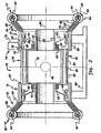
- Figure 2 is a schematic cross-sectional side-elevational view of the MRI magnet of Figure 1 with a cryocooler coldhead and magnet floor mount added.
-
- Referring now to the drawings, wherein like numerals represent like elements throughout, Figures 1-2 show the open magnetic resonance imaging (MRI)
magnet 10. Themagnet 10 includes a toroidal-shaped superconductivefirst coil assembly 12, a toroidal-shaped superconductivesecond coil assembly 14 spaced apart from thefirst coil assembly 12, and a plurality (preferably four) of spaced-apart, parallel, inter-coil-assembly posts 16 each having afirst end 18 attached to thefirst coil assembly 12 and asecond end 20 attached to thesecond coil assembly 14. Themagnet 10 also includes an annular-shaped superconductivefirst shielding assembly 22 spaced-apart from thefirst coil assembly 12 opposite the inter-coil-assembly posts 16 and also includes a plurality (preferably six) of spaced-apart first-assembly posts 24 each having one end 26 attached to thefirst coil assembly 12 and anotherend 28 attached to thefirst shielding assembly 22. Themagnet 10 further includes an annular-shaped superconductivesecond shielding assembly 30 spaced-apart from thesecond coil assembly 14 opposite the inter-coil-assembly posts 16 and further includes a plurality (preferably six) of spaced-apart second-assembly posts 32 each having one end 34 attached to thesecond coil assembly 14 and anotherend 36 attached to thesecond shielding assembly 30. - The
first coil assembly 12 includes an annular-shaped superconductive firstmain coil 38, and thefirst shielding assembly 22 includes an annular-shaped superconductivefirst shielding coil 40 having an inner diameter greater than the outer diameter of the firstmain coil 38. Likewise, thesecond coil assembly 14 includes an annular-shaped superconductive secondmain coil 42, and thesecond shielding assembly 30 includes an annular-shaped superconductivesecond shielding coil 44 having an inner diameter greater than the outer diameter of the secondmain coil 42. All of the first and second coil assemblies 12 and 14 andmain coils second shielding assemblies shielding coils longitudinal axis 46. It is noted that the first and second-assembly posts second shielding coils open MRI magnet 10 to levels acceptable for medical imaging, thefirst coil assembly 12 additionally includes a first bucking coil 50, and thesecond coil assembly 14 additionally includes asecond bucking coil 52. - The first
main coil 38 carries an electric current in a first direction. The first direction is defined to be either a clockwise or a counterclockwise circumferential direction about thelongitudinal axis 46 with any slight longitudinal component of current direction being ignored. The first shielding coil 40 (as well as the first bucking coil 50) carries an electric current in a direction opposite to the first direction (i.e., in a direction opposite to the direction of the electric current carried by the first main coil 38). The secondmain coil 42 carries an electric current in the same direction as that of the firstmain coil 38, thesecond shielding coil 44 carries an electric current in the same direction as that of thefirst shielding coil 40, and thesecond bucking coil 52 carries an electric current in the same direction as that of the first bucking coil 50. Preferably, all of the currents are equal in amperage. - The
first coil assembly 12 has a firstmain coil form 54 supporting the first main coil 38 (and supporting the first bucking coil 50), athermal shield 56 generally spaced apart from and surrounding the firstmain coil 38 and the firstmain coil form 54, and ahousing 58 spaced apart from and surrounding thethermal shield 56 of thefirst coil assembly 12. Thefirst shielding assembly 22 has a firstshielding coil form 60 supporting thefirst shielding coil 40, athermal shield 62 spaced apart from and surrounding thefirst shielding coil 40 and the firstshielding coil form 60, and ahousing 64 spaced apart from and surrounding thethermal shield 62 of thefirst shielding assembly 22. At least one (and preferably all) of the first-assembly posts 24 includes a firstcentral member 66 in thermal contact with the firstshielding coil form 60 and the firstmain coil form 54, athermal shield 68 spaced apart from and surrounding the firstcentral member 66 and in thermal contact with thethermal shield 62 of thefirst shielding assembly 22 and thethermal shield 56 of thefirst coil assembly 12, and ahousing 70 spaced apart from and surrounding thethermal shield 68 of the at least one first-assembly post 24 and in thermal contact with thehousing 64 of thefirst shielding assembly 22 and thehousing 58 of thefirst coil assembly 12. - The
second coil assembly 14 is a mirror image of thefirst coil assembly 12 about a plane 72 (seen on edge as a dashed line in Figure 2) oriented perpendicular to the inter-coil-assembly posts 16 (and perpendicular to the longitudinal axis 46) and disposed equidistant from the first andsecond coil assemblies second shielding assembly 30 is a mirror image of thefirst shielding assembly 22 about theplane 72, and the plurality of spaced-apart second-assembly posts 32 is a mirror image of the plurality of spaced-apart first-assembly posts 24 about theplane 72. - A cryocooler coldhead 74 (such as that of a conventional Gifford McMahon cryocooler), which is also part of the
magnet 10, includes a housing 76 attached to thehousing 58 of thefirst coil assembly 12. The cryocooler coldhead 74 has afirst stage 78 and asecond stage 80. Thefirst stage 78 is in thermal contact with thethermal shield 56 of thefirst coil assembly 12 and is maintained at a temperature of 40 Kelvin. Thesecond stage 80 is in thermal contact with the firstmain coil form 54 of thefirst coil assembly 12 and is maintained at a temperature of 10 Kelvin. - At least one (and preferably all) of the inter-coil-
assembly posts 16 has an inner member 82 in thermal contact with the firstmain coil form 54. The at least oneinter-coil assembly post 16 also has athermal shield 84 spaced apart from and surrounding the inner member 82 and in thermal contact with thethermal shield 56 of thefirst coil assembly 12. The at least oneinter-coil assembly post 16 further has ahousing 86 spaced apart from and surrounding thethermal shield 84 of the at least one inter-coil-assembly post 16 and in thermal contact with thehousing 58 of thefirst coil assembly 12. Afloor mount 88 supports themagnet 10. - A vacuum enclosure is formed by the combination of the
housing 64 of thefirst shielding assembly 22, thehousing 70 of the first-assembly posts 24, thehousing 58 of thefirst coil assembly 12, thehousing 86 of the inter-coil-assembly posts 16, and the corresponding housings (shown but not labeled in Figure 2) of the mirror-imagesecond coil assembly 14, the mirror-image second-assembly posts 32, and the mirror-imagesecond shielding assembly 30. A thermal shield array is formed by the combination of thethermal shield 62 of thefirst shielding assembly 22, thethermal shield 68 of the first-assembly posts 24, thethermal shield 56 of thefirst coil assembly 12, thethermal shield 84 of the inter-coil-assembly posts 16, and the corresponding thermal shields (shown but not labeled in Figure 2) of the mirror-imagesecond coil assembly 14, the mirror-image second-assembly posts 32, and the mirror-imagesecond shielding assembly 30. A thermal conductor structure is formed by the combination of the firstshielding coil form 60 of thefirst shielding assembly 22, the firstcentral members 66 of the first-assembly posts 24, the firstmain coil form 54 of thefirst coil assembly 12, the inner members 82 of the inter-coil-assembly posts 16, and the corresponding members (shown but not labeled in Figure 2) of the mirror-imagesecond coil assembly 14, the mirror-image second-assembly posts 32, and the mirror-imagesecond shielding assembly 30. - Preferably, the
superconductive coils superconductive coils main coil form 54 typically comprises fiberglass (with an aluminum ring, not shown in the figures, to provide thermal conduction and provide support to the radially outward electromagnetic force on the largemain coils 38 and 42), and the firstshielding coil form 60 typically comprises nonmagnetic stainless steel. The firstcentral members 66 of the first-assembly posts 24 and the inner members 82 of the inter-coil-assembly posts 16 typically comprise copper. Thethermal shields housings thermal shield 56 spaced apart from the first main coil form 54) are spaced apart by thermal insulating tubes and the like (not shown in the figures and typically comprising fiberglass). Thermally conductive rings, plates, strips and the like (not shown in the figures and typically comprising copper or aluminum) may be added, as necessary, to provide thermal paths for heat to be removed from all of thesuperconductive coils second stage 80 of thesingle cryocooler coldhead 74. It is noted that a separate cryocooler coldhead is not needed to cool thesuperconductive coils second coil assembly 14 and thesecond shielding assembly 30. - A computer simulation of the
magnet 10 was performed for a 2,500 pound magnet designed to generate a 0.3 Tesla magnetic field within a spherical imaging volume having a diameter of 25 centimeters and having a peak-to-peak magnetic field inhomogeneity of 7.4 ppm (parts-per-million). Applicant designed the shielding for thisparticular magnet 10 using the principles of the present invention, previously disclosed herein, together with conventional magnetic field analysis, as is within the skill of the artisan. The firstmain coil 38 had 414600 amp-turns, thefirst shielding coil 40 had -118680 amp-turns, and the first bucking coil 50 had -104400 amp-turns. The firstmain coil 38 had a mean radius of 36.0 centimeters and was longitudinally disposed a mean distance of 120.6 centimeters from the secondmain coil 42. Thefirst shielding coil 40 was disposed a mean distance of 35.3 centimeters radially outward and 39.0 centimeters longitudinally outward of the firstmain coil 38 The first bucking coil 50 was disposed a mean distance of 15.1 centimeters radially inward and 6.8 centimeters longitudinally inward of the firstmain coil 38. It is noted that "mean radius" is one-half the sum of the inner and outer radii. It is further noted that the "mean distance" between two coils is the closest distance between a circle in each coil, such circle having a center located on the longitudinal axis of the coil equidistant the longitudinal boundaries of the coil and having a radius equal to the mean radius of the coil. Computer simulations showed that with the shielding of the invention, the 5 Gauss stray field was located a longitudinal distance of 2.5 meters and a radial distance of 3.5 meters from the center of theimaging volume 48 of themagnet 10. Without such shielding of the invention, the 5 Gauss stray field was located a longitudinal distance of 7.6 meters and a radial distance of 6.2 meters from the center of theimaging volume 48 of themagnet 10. It is seen that the active superconductive magnetic shielding provided by the invention does not use liquid cryogens, makes theopen magnet 10 easy to site in medical examination rooms, and retains the openness of the open magnet design.
Claims (10)
- An open magnetic resonance imaging magnet comprising:a) a toroidal-shaped superconductive first coil assembly including an annular-shaped superconductive first main coil;b) a toroidal-shaped superconductive second coil assembly being spaced longitudinally from said first coil assembly and including an annular-shaped superconductive second main coil;c) a plurality of spaced-apart, parallel, inter-coil-assembly posts each having a first end attached to said first coil assembly and each having a second end attached to said second coil assembly;
the magnet characterized in that it further comprises :d) an annular-shaped superconductive first shielding assembly including an annular-shaped superconductive first shielding coil having an inner diameter greater than the outer diameter of said first main coil, said first shielding assembly being spaced longitudinally from said first coil assembly in opposite direction to said second coil assembly;e) a plurality of spaced-apart first-assembly posts each having one end attached to said first coil assembly and another end attached to said first shielding assembly;f) an annular-shaped superconductive second shielding assembly including an annular-shaped superconductive second shielding coil having an inner diameter greater than the outer diameter of said second main coil, said second shielding assembly being spaced longitudinally from said second coil assembly in oppssite direction to said first coil assembly; andg) a plurality of spaced-apart second-assembly posts each having one end attached to said second coil assembly and another end attached to said second shielding assembly, wherein all of said first and second coil assemblies and main coils and said first and second shielding assemblies and shielding coils are coaxially aligned. - The magnet of claim 1, wherein:a) said first shielding assembly also includes a first shielding coil form supporting said first shielding coil;b) said first coil assembly also includes a first main coil form supporting said first main coil; andc) at least one of said first-assembly posts includes a first central member in thermal contact with said first shielding coil form and said first main coil form.
- The magnet of claim 2, wherein:a) said first shielding assembly also includes a thermal shield spaced apart from and surrounding said first shielding coil and said first shielding coil form;b) said first coil assembly also includes a thermal shield spaced apart from and surrounding said first main coil and said first main coil form; andc) said at least one first-assembly post includes a thermal shield spaced apart from and surrounding said first central member and in thermal contact with said thermal shield of said first shielding assembly and said thermal shield of said first coil assembly.
- The magnet of claim 3, wherein:a) said first shielding assembly also includes a housing spaced apart from and surrounding said thermal shield of said first shielding assembly;b) said first coil assembly also includes a housing spaced apart from and surrounding said thermal shield of said first coil assembly; andc) said at least one first-assembly post includes a housing spaced apart from and surrounding said thermal shield of said at least one first-assembly post and in thermal contact with said housing of said first shielding assembly and said housing of said first coil assembly.
- The magnet of claim 4, also including a cryocooler coldhead having a housing attached to said housing of said first coil assembly, having a first stage in thermal contact with said thermal shield of said first coil assembly, and having a second stage in thermal contact with said first main coil form of said first coil assembly.
- The magnet of claim 5, wherein at least one of said inter-coil-assembly posts has an inner member in thermal contact with said first main coil form.
- The magnet of claim 6, wherein said at least one inter-coil-assembly post has a thermal shield spaced apart from and surrounding said inner member and in thermal contact with said thermal shield of said first coil assembly.
- The magnet of claim 7, wherein said at least one inter-coil-assembly post has a housing spaced apart from and surrounding said thermal shield of said at least one inter-coil-assembly post and in thermal contact with said housing of said first coil assembly.
- The magnet of claim 8, wherein said second coil assembly is a mirror image of said first coil assembly about a plane oriented perpendicular to said inter-coil-assembly posts and disposed equidistant from said first and second coil assemblies, wherein said second shielding assembly is a mirror image of said first shielding assembly about said plane, and wherein said plurality of spaced-apart second-assembly posts is a mirror image of said plurality of spaced-apart first-assembly posts about said plane.
- The magnet of claim 9; wherein said first coil assembly also includes a first bucking coil; wherein said first main coil has 414600 amp-turns, said first shielding coil has -118680 amp-turns, and said first bucking coil has -104400 amp-turns; wherein said first main coil has a mean radius of 36.0 centimeters and is longitudinally disposed a mean distance of 120.6 centimeters from said second main coil; wherein said first shielding coil is disposed a mean distance of 35.3 centimeters radially outward and 39.0 centimeters longitudinally outward of said first main coil; and wherein said first bucking coil is disposed a mean distance of 15.1 centimeters radially inward and 6.8 centimeters longitudinally inward of said first main coil.
Applications Claiming Priority (2)
| Application Number | Priority Date | Filing Date | Title |
|---|---|---|---|
| US08/260,433 US5448214A (en) | 1994-06-15 | 1994-06-15 | Open MRI magnet with superconductive shielding |
| US260433 | 1994-06-15 |
Publications (2)
| Publication Number | Publication Date |
|---|---|
| EP0687920A1 EP0687920A1 (en) | 1995-12-20 |
| EP0687920B1 true EP0687920B1 (en) | 2003-08-06 |
Family
ID=22989145
Family Applications (1)
| Application Number | Title | Priority Date | Filing Date |
|---|---|---|---|
| EP95303649A Expired - Lifetime EP0687920B1 (en) | 1994-06-15 | 1995-05-30 | MRI magnet |
Country Status (4)
| Country | Link |
|---|---|
| US (1) | US5448214A (en) |
| EP (1) | EP0687920B1 (en) |
| JP (1) | JP3673556B2 (en) |
| DE (1) | DE69531425T2 (en) |
Families Citing this family (38)
| Publication number | Priority date | Publication date | Assignee | Title |
|---|---|---|---|---|
| GB2295673B (en) * | 1994-11-29 | 1999-04-28 | Oxford Magnet Tech | Improvements in or relating to cryogenic mri magnets |
| EP0766094B1 (en) * | 1995-09-28 | 2002-05-29 | Siemens Aktiengesellschaft | Magnet arrangement for a diagnostic magnetic resonance device |
| US5799653A (en) * | 1995-10-03 | 1998-09-01 | Toshiba America Mri, Inc. | Magnetic resonance imaging apparatus with decreased patient claustrophobia and increased access to patient |
| US5568104A (en) * | 1995-10-23 | 1996-10-22 | General Electric Company | Open MRI superconductive magnet with cryogenic-fluid cooling |
| US5565831A (en) * | 1995-10-23 | 1996-10-15 | General Electric Company | Shielded and open MRI magnet |
| US5563566A (en) * | 1995-11-13 | 1996-10-08 | General Electric Company | Cryogen-cooled open MRI superconductive magnet |
| EP0774670B1 (en) * | 1995-11-16 | 2002-05-02 | Siemens Aktiengesellschaft | Magnet assembly for a diagnostic magnetic resonance apparatus |
| JP3731231B2 (en) | 1995-11-30 | 2006-01-05 | 株式会社日立メディコ | Superconducting magnet device |
| US5818319A (en) * | 1995-12-21 | 1998-10-06 | The University Of Queensland | Magnets for magnetic resonance systems |
| DE19548272C1 (en) * | 1995-12-22 | 1997-05-28 | Bruker Analytische Messtechnik | Superconducting NMR magnet arrangement |
| JP3654463B2 (en) * | 1996-03-29 | 2005-06-02 | 株式会社日立メディコ | Magnetic resonance imaging system |
| US6084497A (en) * | 1997-08-05 | 2000-07-04 | The University Of Queensland | Superconducting magnets |
| JP3824412B2 (en) * | 1998-02-17 | 2006-09-20 | 株式会社東芝 | Superconducting magnet device for crystal pulling device |
| US5874880A (en) * | 1998-03-05 | 1999-02-23 | General Electric Company | Shielded and open superconductive magnet |
| US5874882A (en) * | 1998-02-19 | 1999-02-23 | General Electric Company | Open and shielded superconductive magnet |
| US5883558A (en) * | 1998-02-19 | 1999-03-16 | General Electric Company | Open superconductive magnet having shielding |
| US5994991A (en) * | 1998-02-19 | 1999-11-30 | General Electric Company | Open magnet having shielding |
| US6078234A (en) * | 1998-07-09 | 2000-06-20 | General Electric Company | Helium vessel for open architecture magnetic resonance imaging superconducting magnet |
| US6011456A (en) * | 1998-12-30 | 2000-01-04 | Eckels; Phillip W. | Superconducting magnet split cryostat cryogen ride-through reserve |
| US6172588B1 (en) | 1999-04-23 | 2001-01-09 | General Electric Company | Apparatus and method for a superconductive magnet with pole piece |
| US6198371B1 (en) * | 1999-11-09 | 2001-03-06 | General Electric Company | Open magnet with floor mount |
| US6201462B1 (en) | 1999-11-09 | 2001-03-13 | General Electric Company | Open superconductive magnet having a cryocooler coldhead |
| US6396377B1 (en) | 2000-08-25 | 2002-05-28 | Everson Electric Company | Liquid cryogen-free superconducting magnet system |
| JP3939489B2 (en) * | 2000-08-28 | 2007-07-04 | 株式会社日立メディコ | Magnet apparatus and magnetic resonance imaging apparatus using the same |
| AU2001287741A1 (en) * | 2000-09-26 | 2002-04-08 | Koninklijke Philips Electronics N.V. | Vertical field type mri apparatus with a conical cavity situated in the main magnet |
| GB0102654D0 (en) * | 2001-02-02 | 2001-03-21 | Oxford Magnet Tech | Improvements in or relating to magnets |
| US20030079334A1 (en) * | 2001-10-29 | 2003-05-01 | Minfeng Xu | Magnetic homogeneity design method |
| US7061741B2 (en) * | 2003-03-14 | 2006-06-13 | Trench Limited | Method for magnetic field reduction using the decoupling effects of multiple coil systems |
| JP2006115934A (en) * | 2004-10-19 | 2006-05-11 | Mitsubishi Electric Corp | Magnet apparatus and magnetic resonance imaging system using the same |
| DE102006040687A1 (en) * | 2006-08-30 | 2008-03-13 | Bruker Biospin Ag | Split coil magnet assembly with improved mechanical design |
| WO2008073517A1 (en) * | 2006-12-07 | 2008-06-19 | Ehrenpreis Eli D | Treatment for intestinal gas, bloating, microscopic colitis and traveler's diarrhea using colloidal bismuth subcitrate |
| WO2008100546A1 (en) * | 2007-02-13 | 2008-08-21 | The Government Of The United States Of America, As Represented By The Secretary, Department Of Health And Human Services | Transmit profile control in mri |
| US8279030B2 (en) * | 2008-09-27 | 2012-10-02 | Magnetic-Electrostatic Confinement (Mec) Corporation | Method and apparatus for electrical, mechanical and thermal isolation of superconductive magnets |
| WO2010067272A1 (en) * | 2008-12-11 | 2010-06-17 | Philips Intellectual Property & Standards Gmbh | Arrangement for influencing and/or detecting magnetic particles in a region of action |
| CN101819845B (en) * | 2010-04-16 | 2012-07-04 | 中国科学院电工研究所 | Superconducting magnet system for high power microwave source focusing and cyclotron electronic device |
| US11385312B2 (en) * | 2015-03-27 | 2022-07-12 | Michael Hutchinson | Ultrafast MRI system and method |
| US10877122B2 (en) * | 2015-03-27 | 2020-12-29 | Michael Hutchinson | Ultrafast MRI system and method |
| US10784001B2 (en) | 2018-01-17 | 2020-09-22 | Lockheed Martin Corporation | Passive magnetic shielding of structures immersed in plasma using superconductors |
Family Cites Families (18)
| Publication number | Priority date | Publication date | Assignee | Title |
|---|---|---|---|---|
| DE3227844A1 (en) * | 1982-07-26 | 1984-01-26 | Siemens AG, 1000 Berlin und 8000 München | DEVICE FOR ADJUSTING AND HOLDING MAGNETIC COILS OF A MAGNETIC SYSTEM FOR CORE SPIN TOMOGRAPHY |
| FR2541551A1 (en) * | 1983-02-21 | 1984-08-24 | Drusch & Cie | DEVICE FOR HOLDING AND FIXING COILS FOR REALIZING A CONSTANT AND HOMOGENEOUS MAGNETIC FIELD |
| JPS59172403U (en) * | 1983-04-30 | 1984-11-17 | 株式会社東芝 | Diagnostic nuclear magnetic resonance apparatus |
| FI70751C (en) * | 1983-05-20 | 1986-10-06 | Instrumentarium Oy | SPOLANORDNING FOR NMR-UNDERSOEKNINGSUTRUSTNING |
| US4581580A (en) * | 1983-12-14 | 1986-04-08 | General Electric Company | Intentionally non-orthogonal correction coils for high-homogeneity magnets |
| US4506247A (en) * | 1984-05-23 | 1985-03-19 | General Electric Company | Axisymmetric correction coil system for NMR magnets |
| US4500860A (en) * | 1984-07-05 | 1985-02-19 | General Electric Company | Winding support and method for NMR magnet axisymmetric correction coils |
| US4509030A (en) * | 1984-07-05 | 1985-04-02 | General Electric Company | Correction coil assembly for NMR magnets |
| US4595899A (en) * | 1984-07-06 | 1986-06-17 | The Board Of Trustees Of The Leland Stanford Junior University | Magnetic structure for NMR applications and the like |
| US4523166A (en) * | 1984-10-19 | 1985-06-11 | General Electric Company | Optimal field inhomogeneity correction coil operation for NMR magnets |
| EP0243669B1 (en) * | 1986-04-21 | 1991-04-10 | Siemens Aktiengesellschaft | Frame structure for a magnet assembly for use in a magnetic-resonance imaging apparatus |
| US4724412A (en) * | 1987-08-03 | 1988-02-09 | General Electric Company | Method of determining coil arrangement of an actively shielded magnetic resonance magnet |
| US4935714A (en) * | 1988-07-05 | 1990-06-19 | General Electric Company | Low thermal conductance support for a radiation shield in a MR magnet |
| US4924198A (en) * | 1988-07-05 | 1990-05-08 | General Electric Company | Superconductive magnetic resonance magnet without cryogens |
| EP0424808A1 (en) * | 1989-10-21 | 1991-05-02 | Kabushiki Kaisha Toshiba | Magnetic resonance imaging apparatus |
| US5006804A (en) * | 1989-12-04 | 1991-04-09 | General Electric Company | Method of optimizing shim coil current selection in magnetic resonance magnets |
| US5237300A (en) * | 1992-08-03 | 1993-08-17 | General Electric Company | Support structure for actively shielded superconducting magnets |
| US5291169A (en) * | 1992-11-02 | 1994-03-01 | General Electric Company | Open architecture magnetic resonance imaging superconducting magnet assembly |
-
1994
- 1994-06-15 US US08/260,433 patent/US5448214A/en not_active Expired - Fee Related
-
1995
- 1995-05-30 DE DE69531425T patent/DE69531425T2/en not_active Expired - Fee Related
- 1995-05-30 EP EP95303649A patent/EP0687920B1/en not_active Expired - Lifetime
- 1995-06-09 JP JP14228395A patent/JP3673556B2/en not_active Expired - Fee Related
Also Published As
| Publication number | Publication date |
|---|---|
| JPH08102416A (en) | 1996-04-16 |
| EP0687920A1 (en) | 1995-12-20 |
| DE69531425T2 (en) | 2004-07-01 |
| DE69531425D1 (en) | 2003-09-11 |
| US5448214A (en) | 1995-09-05 |
| JP3673556B2 (en) | 2005-07-20 |
Similar Documents
| Publication | Publication Date | Title |
|---|---|---|
| EP0687920B1 (en) | MRI magnet | |
| US5410287A (en) | Open MRI magnet with uniform magnetic field | |
| US5565831A (en) | Shielded and open MRI magnet | |
| US5416415A (en) | Over-shoulder MRI magnet for human brain imaging | |
| US5999075A (en) | Open magnet with shielding | |
| US5428292A (en) | Pancake MRI magnet with modified imaging volume | |
| US5721523A (en) | Compact MRI superconducting magnet | |
| US5574417A (en) | Open MRI magnet with homogeneous imaging volume | |
| US6396376B1 (en) | Apparatus and method for a superconductive magnet with pole piece | |
| JPH10225447A (en) | Plane-type magnetic resonance imaging magnet | |
| JP3663262B2 (en) | Open magnetic resonance imaging magnet | |
| EP0937994B1 (en) | Open and shielded supercondutive magnet | |
| US5517169A (en) | Superconducting magnet with magnetic shielding | |
| US6157279A (en) | Open magnet having shielding | |
| US5568110A (en) | Closed MRI magnet having reduced length | |
| EP0757256A2 (en) | Open architecture magnetic resonance imaging superconducting magnet assembly | |
| US5568102A (en) | Closed superconductive magnet with homogeneous imaging volume | |
| US5594401A (en) | Closed superconductive magnet with uniform imaging volume | |
| US5517168A (en) | Superconducting magnet with magnetic shielding | |
| US5521571A (en) | Open MRI magnet with uniform imaging volume | |
| EP0940687A2 (en) | Open magnet with shielding | |
| EP0826978A1 (en) | Closed MRI magnet having compact design |
Legal Events
| Date | Code | Title | Description |
|---|---|---|---|
| PUAI | Public reference made under article 153(3) epc to a published international application that has entered the european phase |
Free format text: ORIGINAL CODE: 0009012 |
|
| AK | Designated contracting states |
Kind code of ref document: A1 Designated state(s): DE GB NL |
|
| 17P | Request for examination filed |
Effective date: 19960620 |
|
| GRAH | Despatch of communication of intention to grant a patent |
Free format text: ORIGINAL CODE: EPIDOS IGRA |
|
| GRAH | Despatch of communication of intention to grant a patent |
Free format text: ORIGINAL CODE: EPIDOS IGRA |
|
| GRAA | (expected) grant |
Free format text: ORIGINAL CODE: 0009210 |
|
| AK | Designated contracting states |
Designated state(s): DE GB NL |
|
| REG | Reference to a national code |
Ref country code: GB Ref legal event code: FG4D |
|
| REF | Corresponds to: |
Ref document number: 69531425 Country of ref document: DE Date of ref document: 20030911 Kind code of ref document: P |
|
| PLBE | No opposition filed within time limit |
Free format text: ORIGINAL CODE: 0009261 |
|
| STAA | Information on the status of an ep patent application or granted ep patent |
Free format text: STATUS: NO OPPOSITION FILED WITHIN TIME LIMIT |
|
| 26N | No opposition filed |
Effective date: 20040507 |
|
| PGFP | Annual fee paid to national office [announced via postgrant information from national office to epo] |
Ref country code: NL Payment date: 20050429 Year of fee payment: 11 |
|
| PGFP | Annual fee paid to national office [announced via postgrant information from national office to epo] |
Ref country code: GB Payment date: 20050525 Year of fee payment: 11 |
|
| PGFP | Annual fee paid to national office [announced via postgrant information from national office to epo] |
Ref country code: DE Payment date: 20050630 Year of fee payment: 11 |
|
| PG25 | Lapsed in a contracting state [announced via postgrant information from national office to epo] |
Ref country code: GB Free format text: LAPSE BECAUSE OF NON-PAYMENT OF DUE FEES Effective date: 20060530 |
|
| PG25 | Lapsed in a contracting state [announced via postgrant information from national office to epo] |
Ref country code: NL Free format text: LAPSE BECAUSE OF NON-PAYMENT OF DUE FEES Effective date: 20061201 Ref country code: DE Free format text: LAPSE BECAUSE OF NON-PAYMENT OF DUE FEES Effective date: 20061201 |
|
| GBPC | Gb: european patent ceased through non-payment of renewal fee |
Effective date: 20060530 |
|
| NLV4 | Nl: lapsed or anulled due to non-payment of the annual fee |
Effective date: 20061201 |