EP0685834A1 - A speech synthesis method and a speech synthesis apparatus - Google Patents
A speech synthesis method and a speech synthesis apparatus Download PDFInfo
- Publication number
- EP0685834A1 EP0685834A1 EP95303606A EP95303606A EP0685834A1 EP 0685834 A1 EP0685834 A1 EP 0685834A1 EP 95303606 A EP95303606 A EP 95303606A EP 95303606 A EP95303606 A EP 95303606A EP 0685834 A1 EP0685834 A1 EP 0685834A1
- Authority
- EP
- European Patent Office
- Prior art keywords
- pitch
- waveform
- speech
- speech synthesis
- synthesis method
- Prior art date
- Legal status (The legal status is an assumption and is not a legal conclusion. Google has not performed a legal analysis and makes no representation as to the accuracy of the status listed.)
- Granted
Links
- 230000015572 biosynthetic process Effects 0.000 title claims abstract description 113
- 238000003786 synthesis reaction Methods 0.000 title claims abstract description 113
- 238000001308 synthesis method Methods 0.000 title claims abstract description 24
- 239000011159 matrix material Substances 0.000 claims abstract description 41
- 230000003595 spectral effect Effects 0.000 claims abstract description 27
- 230000004044 response Effects 0.000 claims abstract description 24
- 238000004364 calculation method Methods 0.000 claims abstract description 22
- 238000005070 sampling Methods 0.000 claims description 37
- 238000001228 spectrum Methods 0.000 claims description 8
- 238000005316 response function Methods 0.000 claims description 3
- 238000009795 derivation Methods 0.000 claims 3
- 230000010363 phase shift Effects 0.000 claims 1
- 239000011295 pitch Substances 0.000 description 383
- 238000000034 method Methods 0.000 description 61
- 230000014509 gene expression Effects 0.000 description 45
- 238000010586 diagram Methods 0.000 description 38
- 238000010606 normalization Methods 0.000 description 36
- 238000012545 processing Methods 0.000 description 22
- 230000006870 function Effects 0.000 description 12
- 238000007796 conventional method Methods 0.000 description 5
- 238000006243 chemical reaction Methods 0.000 description 2
- 238000004891 communication Methods 0.000 description 2
- 230000006866 deterioration Effects 0.000 description 2
- 238000007620 mathematical function Methods 0.000 description 2
- 230000005540 biological transmission Effects 0.000 description 1
- 230000003247 decreasing effect Effects 0.000 description 1
- 230000002194 synthesizing effect Effects 0.000 description 1
- 238000012546 transfer Methods 0.000 description 1
Images


Classifications
-
- G—PHYSICS
- G10—MUSICAL INSTRUMENTS; ACOUSTICS
- G10L—SPEECH ANALYSIS TECHNIQUES OR SPEECH SYNTHESIS; SPEECH RECOGNITION; SPEECH OR VOICE PROCESSING TECHNIQUES; SPEECH OR AUDIO CODING OR DECODING
- G10L13/00—Speech synthesis; Text to speech systems
- G10L13/02—Methods for producing synthetic speech; Speech synthesisers
- G10L13/033—Voice editing, e.g. manipulating the voice of the synthesiser
-
- G—PHYSICS
- G10—MUSICAL INSTRUMENTS; ACOUSTICS
- G10L—SPEECH ANALYSIS TECHNIQUES OR SPEECH SYNTHESIS; SPEECH RECOGNITION; SPEECH OR VOICE PROCESSING TECHNIQUES; SPEECH OR AUDIO CODING OR DECODING
- G10L13/00—Speech synthesis; Text to speech systems
- G10L13/08—Text analysis or generation of parameters for speech synthesis out of text, e.g. grapheme to phoneme translation, prosody generation or stress or intonation determination
Definitions
- the present invention relates to a speech synthesis method and a speech synthesis apparatus that employ a system for synthesis by rule.
- Conventional apparatuses for speech synthesis by rule employ, as a method for generating synthesized speech, a synthesis filter system (PARCOR, LESP, or MSLA), a waveform editing system, or a superposition system for an impulse response waveform.
- a synthesis filter system PARCOR, LESP, or MSLA
- waveform editing system or a superposition system for an impulse response waveform.
- Speech synthesis that is performed by a synthesis filter system requires many calculations before a speech waveform can be generated, and not only is the load that is placed on the apparatus large, but a long processing time is also required.
- speech synthesis performed by a waveform editing system since a complicated process must be performed to change the tones of synthesized speech, the load placed on the apparatus is large, and because a complicated waveform editing process must be performed, the quality of the synthesized speech is deteriorated compared with the one before editing.
- Speech synthesis that is performed by an impulse response waveform superposition system deteriorates the quality of sounds in portions where waveforms are superposed.
- a speech synthesis apparatus comprises: generation means for generating pitch waveforms by employing a pitch and a parameter of synthesized speech and for connecting the pitch waveforms to provide a speech waveform; and generation means for generating an unvoiced waveform using a parameter of synthesized speech and for connecting the unvoiced waveforms to provide a speech waveform that can prevent the deterioration of sound quality for an unvoiced waveform.
- a product of a matrix, which is acquired in advance, and a parameter is calculated for the generation of unvoiced speech, so that the number of calculations that are required for the generation of an unvoiced waveforms can be reduced.
- Pitch waveforms having shifted phases, are generated and linked together to represent a decimal portion of a pitch period point number, so that the exact pitch can be provided for a speech waveform in which is included a decimal portion.
- synthesized speech for an arbitrary sampling frequency can be generated by a simple method.
- a mathematical function that determines a frequency response is employed to multiply a function value integer times a pitch frequency, and a sample value for a spectral envelope, which is obtained by using a parameter, is transformed. Fourier transform is performed on the resultant, transformed sample value to provide a pitch waveform, so that the timbre of synthesized speech can be changed without performing a complicated process, such as a parameter operation.
- a speech waveform can be generated by using a parameter in a frequency range and a parameter operation in the frequency range can be performed.
- a function that decides a frequency response is employed to multiply a function value integer times a pitch frequency, and a sample value of a spectral envelope that is acquired by a parameter is transformed. Then, a Fourier transform is performed on the transformed sample value to generate a pitch waveform, so that the timbre of the synthesized speech can be altered without parameter operations.
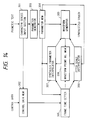
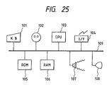
- Fig. 25 is a block diagram illustrating the arrangement of a speech synthesis apparatus according to one embodiment of the present invention.
- a keyboard (KB) 101 is employed to input text for synthesized speech and to input control commands, etc..
- a pointing device 102 is employed to input a desired position on the display screen of a display 108; by positioning a pointing icon with this device, desired control commands, etc., can be input.
- a central processing unit (CPU) 103 controls various processes, in the embodiment that will be described later, that are executed by the apparatus of the present invention, and performs processing by executing a control program that is stored in a read only memory (ROM) 105.
- a communication interface (I/F) 104 is employed to control the transmission and the reception of data across various communication networks.
- the ROM 105 is employed for storing a control program for a process that is shown in a flowchart for this embodiment.
- a random access memory (RAM) 106 is employed as a means for storing data that are generated by various processes in the embodiment.
- a loudspeaker 107 is used to output sounds, such as synthesized speech and messages for an operator.
- the display 108 an apparatus such as an LCD or a CRT, is employed to display text that are input at the keyboard and data that are being processed.
- a bus 109 is used to transfer data and commands between the individual components.
- Fig. 1 is a block diagram illustrating the functional arrangement of a synthesis apparatus according to Embodiment 1 of the present invention. These functions are executed under the control of the CPU 103 in Fig. 25.
- a character series input section 1 inputs a character series for a speech that is to be synthesized. When speech to be synthesized is for example, a character series of phonetic text, such as "AIUEO", is input. Aside from phonetic text, character series that are input by the character series input section 1 indicate control sequences that are for determining utterance speeds and pitches. The character series input section 1 determines whether or not an input character series is phonetic text or a control sequence.
- Character series that are determined as control sequences by the character series input section 1, and control data for utterance speeds and pitches that are input via a user interface are transmitted to a control data memory 2 and stored in the internal register of the control data memory 2.
- a parameter generator 3 reads a parameter series, which is stored in advance from the ROM 105 in consonance with a character series that is input by the character series input section 1 and that is determined to be phonetic text.
- a parameter of a frame that is to be processed is extracted from the parameter series that is generated by the parameter generator 3 and is stored in the internal register of a parameter memory 4.
- a frame time setter 5 calculates time length Ni for each frame by employing control data that concern utterance speeds and that are stored in the control data memory 2, and utterance speed coefficient K (a parameter used for determining a frame time length in consonance with utterance speed), which is stored in the parameter memory 4.
- a waveform point number memory 6 is employed to store in its internal register acquired waveform point number n W for one frame.
- a synthesis parameter interpolator 7 interpolates synthesis parameters, which are stored in the parameter memory 4, by using frame time length Ni, which is set by the frame time setter 5, and waveform point number n W , which is stored in the waveform point number memory 6.
- a pitch scale interpolator 8 interpolates pitch scales, which are stored in the parameter memory 4, by using frame time length Ni, which is set by the frame time setter 5, and waveform point number n w , which is stored in the waveform point number memory 6.
- a waveform generator 9 generates a pitch waveform by using a synthesis parameter, which has been interpolated by the synthesis parameter interpolator 7, and a pitch scale, which has been interpolated by the pitch scale interpolator 8, and links the pitch waveforms to output synthesized speech.
- a synthesis parameter that is employed for the generation of a pitch waveform will be explained.
- N the power of the Fourier transform
- M the power of a synthesis parameter
- N and M satisfy N ⁇ 2M.
- a logarithm power spectrum envelope for speech is The logarithm power spectrum envelope is substituted in an exponentional function to return the envelope to a linear form, and a reverse Fourier transform is performed on the resultant envelope.
- the acquired impulse response is
- Synthesis parameter p(m) (0 ⁇ m ⁇ M) is acquired by doubling the ratio of a value of the power of 0 of the impulse response and a value of the power of 1 and the following number of the impulse response.
- a pitch frequency of synthesized speech is f
- N p (f) [N p (f)].
- a pitch waveform is w (k) (0 ⁇ k ⁇ N p (f)), and a power normalization coefficient that corresponds to pitch frequency f is C (f).
- pitch waveform w (k) (0 ⁇ k ⁇ N p (f)) can be generated (Fig. 5):
- the pitch scale is employed as a scale for representing the tone of speech.
- pitch period point number N p (s) and power normalization coefficient C (s) that correspond to pitch scale s are stored in a table.
- step S1 phonetic text is input by the character series input section 1.
- control data (utterance speed, pitch of speech, etc.) that are externally input, and control data for the input phonetic text are stored in the control data memory 2.
- the parameter generator 3 generates a parameter series for the phonetic text that has been input by the character series input section 1.
- FIG. 8 A data structure example for one frame of parameters that are generated at step S3 is shown in Fig. 8.
- n W 0.
- step S5 parameter series counter i is initialized to 0.
- step S6 parameters for the ith frame and the (i+1)th frame are fetched from the parameter generator 3 to the internal register of the parameter memory 4.
- step S7 utterance speed is fetched from the control data memory 2 to the frame time setter 5.
- the frame time setter 5 employs utterance speed coefficients for the parameters, which have been fetched to the parameter memory 4, and utterance speed that has been fetched from the control data memory 2 to set frame time length Ni.
- step S9 a check is performed to ascertain whether or not waveform point number n W is smaller than frame time length Ni in order to determine whether or not the process for the ith frame has been completed.
- n W ⁇ Ni it is assumed that the process for the ith frame has been completed, and program control advances to step S14.
- n W ⁇ Ni it is assumed that the process for the ith frame is in the process of being performed and program control moves to step S10 where the process is continued.
- the synthesis parameter interpolator 7 employs the synthesis parameter, which is stored in the parameter memory 4, the frame time length, which is set by the frame time setter 5, and the waveform point number, which is stored in the waveform point number memory 6, to perform interpolation for the synthesis parameter.
- Fig. 9 is an explanatory diagram for the interpolation of the synthesis parameter.
- a synthesis parameter for the ith frame is denoted by pi [m] (0 ⁇ m ⁇ M)
- a synthesis parameter for the (i+1)th frame is denoted by P i+1 [m] (0 ⁇ m ⁇ M)
- the time length for the ith frame is denoted by N i point.
- synthesis parameter p [m] (0 ⁇ m ⁇ M) is updated each time a pitch waveform is generated.
- the process p [m] p i [m] + n W ⁇ p [m] is performed at the starting point for a pitch waveform.
- the pitch scale interpolator 8 employs the pitch scale, which is stored in the parameter memory 4, the frame time length, which is set by the frame time setter 5, and the waveform point number, which is stored in the waveform point number memory 6, to interpolate the pitch scale.
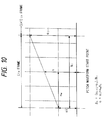
- Fig. 10 is an explanatory diagram for the interpolation of pitch scales.
- a pitch scale for the ith frame is s i
- a pitch scale of the (i+1)th frame is s i+1
- the N i point is a frame time length for the ith frame.
- pitch scale s is updated each time a pitch waveform is generated.
- the waveform generator 9 employs synthesis parameter p [m] (0 ⁇ m ⁇ M), which is obtained from equation (3), and pitch scale s, which is obtained from equation (4), to generate a pitch waveform.
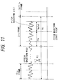
- Fig. 11 is an explanatory diagram for the linking of generated pitch waveforms.
- a speech waveform that is output as synthesized speech by the waveform generator 9 is represented as W (n) (0 ⁇ n).
- the pitch waveforms are linked by the following equations:
- step S9 When, at step S9, n W ⁇ N i , program control goes to step S14.
- n W n W - N i .
- step S15 a check is performed to determine whether or not the process for all the frames has been completed.
- program control goes to step S16.
- step S16 the control data (utterance speed, pitch of speech, etc.) that are input externally are stored in the control data memory 2.
- step S15 the process for all the frames has been completed, the processing is thereafter terminated.
- Embodiment 1 the structure and the functional arrangement of a speech synthesis apparatus according to Embodiment 2 are shown in the block diagrams in Figs. 25 and 1.
- a synthesis parameter that is employed for generation of a pitch waveform is p(m) (0 ⁇ m ⁇ M) and a sampling frequency is f s .
- a pitch frequency of synthesized speech is f
- the notation [x] represents an integer that is equal to or smaller than x.
- the decimal portion of a pitch period point number is represented by linking pitch waveforms that are shifted in phase.
- the number of pitch waveforms that correspond to frequency f is the number of phases n p (f).
- ⁇ 1 2 ⁇ N p (f) .
- phase index i p (0 ⁇ i p ⁇ n p (f)).
- the pitch waveform point number that corresponds to phase index i p is calculated by the equation of:
- a pitch frequency is altered to f' for the generation of the next pitch waveform
- a value of i' is calculated to satisfy in order to acquire a phase angle that is the closest to ⁇ p
- the pitch scale is employed as a scale for representing the tone of speech.
- the speed of calculation can be increased as follows.
- n p (s) is a phase number that corresponds to pitch scale s ⁇ S (S denotes a set of pitch scales)
- i p (0 ⁇ i p ⁇ n p (s)) is a phase index
- N (s) is an expanded pitch period point number
- N p (s) is a pitch period point number
- P (s, i p ) is a pitch waveform point number
- a phase angle of ⁇ ( s,i p ) 2 ⁇ n p (s) i p , which corresponds to pitch scale s and phase index i p , is stored in the table.
- phase number n p (s), pitch waveform point number p (s, i p ), and power normalization coefficient C (s), each of which corresponds to pitch scale s and phase index i p are stored in the table.
- phase index that is stored in the internal register is defined as i p
- phase angle is defined as ⁇ p
- synthesis parameter p (m) (0 ⁇ m ⁇ M)
- pitch scale s which is output by the pitch scale interpolator 8
- step S201 phonetic text is input by the character series input section 1.
- control data (utterance speed, pitch of speech, etc.) that are externally input and control data for the input phonetic text are stored in the control data memory 2.
- the parameter generator 3 generates a parameter series with the phonetic text that has been input by the character series input section 1.
- the data structure for one frame of parameters that are generated at step S203 is the same as that of Embodiment 1 and is shown in Fig. 8.
- n W 0.
- step S205 parameter series counter i is initialized to 0.
- phase index i p is initialized to 0, and phase angle ⁇ p is initialized to 0.
- step S207 parameters for the ith frame and the (i+1)th frame are fetched from the parameter generator 3 and stored in the parameter memory 4.
- utterance speed data is fetched from the control data memory 2 for use by the frame time setter 5.
- the frame time setter 5 employs utterance speed coefficients for the parameters, which have been fetched into the parameter memory 4, and utterance speed data that have been fetched from the control data memory 2 to set frame time length Ni.
- step S210 a check is performed to determine whether or not waveform point number n W is smaller than frame time length Ni.
- program control advances to step S217.
- program control moves to step S211 where the process is continued.
- the synthesis parameter interpolator 7 employs the synthesis parameter, which is stored in the parameter memory 4, the frame time length, which is set by the frame time setter 5, and the waveform point number, which is stored in the waveform point number memory 6, to perform interpolation for the synthesis parameter.
- the parameter interpolation is performed in the same manner as at step S10 in Embodiment 1.
- the pitch scale interpolator 8 employs the pitch scale, which is stored in the parameter memory 4, the frame time length, which is set by the frame time setter 5, and the waveform point number, which is stored in the waveform point number memory 6 to interpolate the pitch scale.
- the pitch scale interpolation is performed in the same manner as at step S11 in Embodiment 1.
- the waveform generator 9 employs synthesis parameter p [m] (0 ⁇ m ⁇ M), which is obtained by equation (3), and pitch scale s, which is obtained by equation (4) to generate a pitch waveform.
- a speech waveform that is output as synthesized speech by the waveform generator 9 is defined as W (n) (0 ⁇ n).
- the pitch waveforms are linked in the same manner as in Embodiment 1. With the time length for the jth frame defined as N j ,
- step S210 When, at step S210, n W ⁇ N i , program control goes to step S217.
- n W n W - N i .
- step S218 a check is performed to determine whether or not the process for all the frames has been completed. When the process has not yet been completed, program control goes to step S219.
- control data (utterance speed, pitch of speech, etc.) that are input externally are stored in the control data memory 2.
- Fig. 14 is a block diagram illustrating the functional arrangement of a speech synthesis apparatus in Embodiment 3. The individual functions are performed under the control of the CPU 103 in Fig. 25.
- a character series input section 301 inputs a character series of speech to be synthesized. When speech to be synthesized is, for example, "voice", a character series of such phonetic text as "OnSEI" is input. In addition to a phonetic text, the character series that is input by the character series input section 1 sometimes includes a character series that constitutes a control sequence for setting utterance speed and a speech pitch.
- the character series input section 301 determines whether or not the input character series is phonetic text or a control sequence.
- a control data memory 302 is an internal register, where are stored a character series, which is determined as a control sequence by the character series input section 301 and forwarded thereto, and control data, such as utterance speed and speech pitch, which are input by a under interface.
- a parameter generator 303 reads, from the ROM 105, a parameter series that is stored in advance in consonance with a character series, which has been input and has been determined to be phonetic text by the character series input section 301, and generates a parameter series. Parameters for a frame that is to be processed are extracted from the parameter series that is generated by the parameter generator 303, and are stored in the internal register of a parameter memory 304.
- a frame time setter 305 employs control data that concern utterance speed, which is stored in the control data memory 302, and utterance speed coefficient K (parameter employed for determining a frame time length in consonance with utterance speed), which is stored in the parameter memory 304, and calculates time length N i for each frame.
- a waveform point number memory 306 has an internal register wherein is stored acquired waveform point number n w for each frame.
- a synthesis parameter interpolator 307 interpolates synthesis parameters that are stored in the parameter memory 304 by using frame time length N i , which is set by the frame time length setter 305, and waveform point number n w , which is stored in the waveform point number memory 306.
- a pitch scale interpolator 308 interpolates a pitch scale that is stored in the parameter memory 304 by using frame time length n i , which is set by the frame time length setter 305, and waveform point number n w , which is stored in the waveform point number memory 306.
- a waveform generator 309 generates pitch waveforms by using a synthesis parameter, which is obtained as a result of the interpolation by the synthesis parameter interpolator 307, and a pitch scale, which is obtained as a result of the interpolation by the pitch scale interpolator 308, and links together the pitch waveforms, so that synthesized speech is output.
- the waveform generator 309 generates unvoiced waveforms by employing a synthesis parameter that is output by the synthesis parameter interpolator 307, and links the unvoiced waveforms together to output synthesized speech.
- the processing performed by the waveform generator 309 to generate a pitch waveform is the same as that performed by the waveform generator 9 in Embodiment 1.
- a synthesis parameter that is employed for generation of an unvoiced waveform is p(m) (0 ⁇ m ⁇ M) and a sampling frequency is f s .
- a pitch frequency of a sine wave that is employed for the generation of an unvoiced waveform is denoted by f, which is set to a frequency that is lower than an audio frequency band.
- the notation [x] represents an integer that is equal to or smaller than x.
- the pitch period point number that corresponds to pitch frequency f is
- the value of a spectral envelope that is integer times as large as the pitch frequency f is expressed as follows:
- the expanded unvoiced waveform is w uv (k) (0 ⁇ k ⁇ N uv ), and a power normalization coefficient that corresponds to pitch frequency f is C (f).
- C (f) f 0
- Sine waves that are integer times as large as a pitch frequency are superposed while their phases are shifted at random to provide an unvoiced waveform.
- a shift in phases is denoted by ⁇ 1 (1 ⁇ 1 ⁇ [N uv /2]).
- the expression ⁇ 1 is set to a random value such that it satisfies - ⁇ ⁇ ⁇ 1 ⁇ ⁇ .
- unvoiced waveform w uv (k) (0 ⁇ k ⁇ N uv ) can be generated as follows:
- the speed of computation can be increased as follows. With an unvoiced waveform index as i uv (0 ⁇ i uv ⁇ N uv ), is calculated and stored in the table.
- UVWGM (i uv ) (c (i uv , m)) (0 ⁇ i uv ⁇ N uv , 0 ⁇ m ⁇ M).
- pitch period point number N uv and power normalization coefficient C uv are stored in the table.
- step S301 phonetic text is input by the character series input section 301.
- control data (utterance speed, pitch of speech, etc.) that are externally input and control data for the input phonetic text are stored in the control data memory 302.
- the parameter generator 303 generates a parameter series with the phonetic text that has been input by the character series input section 301.
- the data structure for one frame of parameters that are generated at step S303 is shown in Fig. 16.
- n W 0.
- step S305 parameter series counter i is initialized to 0.
- unvoiced waveform index i uv is initialized to 0.
- step S307 parameters for the ith frame and the (i+1)th frame are fetched from the parameter generator 303 into the parameter memory 304.
- utterance speed data are fetched from the control data memory 302 for use by the frame time setter 305.
- the frame time setter 305 employs utterance speed coefficients for the parameters, which have been fetched and stored in the parameter memory 304, and utterance speed data that have been fetched from the control data memory 302 to set frame time length Ni.
- step S310 voiced or unvoiced parameter information that is fetched and stored in the parameter memory 304 is employed to determine whether or not the parameter of the ith frame is for an unvoiced waveform. If the parameter for that frame is for an unvoiced waveform, program control advances to step S311. If the parameter is for a voiced waveform, program control moves to step S317.
- step S311 a check is performed to determine whether or not waveform point number n W is smaller than frame time length Ni.
- program control advances to step S315.
- program control moves to step S312 where the process is continued.
- the waveform generator 9 employs a synthesis parameter for the ith frame, p i [m] (0 ⁇ m ⁇ M), which is input by the synthesis parameter interpolator 307, to generate an unvoiced waveform.
- a speech waveform that is output as synthesized speech by the waveform generator 309 is defined as W (n) (0 ⁇ n).
- the unvoiced waveforms are linked with the time length for the jth frame being defined as N j from the equation
- step S310 When, at step S310, information indicates an unvoiced parameter, program control moves to step S317, where pitch waveforms for the ith frame are generated and are linked together.
- step S317 The processing at this step is the same as that which is performed at steps S9 through S13 in Embodiment 1.
- step S316 a check is performed to determine whether or not the process for all the frames has been completed.
- program control goes to step S318.
- step S318 the control data (utterance speed, pitch of speech, etc.) that are input externally are stored in the control data memory 302.
- step S316 the process for all the frames has been completed, the processing is thereafter terminated.
- Embodiment 4 The structure and the functional arrangement of a speech synthesis apparatus according to Embodiment 4 are shown in the block diagrams in Figs. 25 and 1, as for Embodiment 1.
- a synthesis parameter that is employed for generation of a pitch waveform is p(m) (0 ⁇ m ⁇ M) and a sampling frequency, for an impulse response waveform, that is a synthesis parameter is defined as an analysis sampling frequency of f s1 .
- pitch waveform w (k) (0 ⁇ k ⁇ N p2 (f)
- pitch waveform w (k) (0 ⁇ k ⁇ N p2 (f)) can be generated by the following expression:
- the pitch scale is employed as a scale for representing the tone of speech.
- the speed of calculation can be increased as follows.
- N p1 (s) is a phase number that corresponds to pitch scale s ⁇ S (S denotes a set of pitch scales)
- N p2 (s) is an synthesis pitch period point number
- equations ⁇ 1 2 ⁇ N p1 (s)
- ⁇ 2 2 ⁇ N p2 (s)
- synthesis pitch period point number N p2 (s) and power normalization coefficient C(s), both of which correspond to pitch scale s, are stored in the table.
- synthesis parameter p (m) (0 ⁇ m ⁇ M)
- pitch scale s which is output by the pitch scale interpolator 8
- power normalization coefficient C (s) power normalization coefficient C (s)
- waveform generation matrix WGM (s) (c km (s))
- the waveform generator 9 employs synthesis parameter p [m] (0 ⁇ m ⁇ M), which is obtained by using equation (3), and pitch scale s, which is obtained by using equation (4), to generate a pitch waveform.
- a speech waveform that is output as synthesized speech by the waveform generator 9 is defined as W (n) (0 ⁇ n).
- the pitch waveforms are linked together with the time length for the jth frame, which is defined as N j , so that
- a pitch waveform is generated by a power spectrum envelope to enable parameter operations, within a frequency range, that employs the power spectral envelope.
- Embodiment 1 the structure and the functional arrangement of a speech synthesis apparatus in Embodiment 5 are shown in Figs. 25 and 1.
- a synthesis parameter that is employed for the generation of a pitch waveform will be explained.
- N the power of the Fourier transform
- M the power of a synthesis parameter
- N and M satisfy N ⁇ 2M.
- a logarithm power spectrum envelope for speech is The logarithm power spectrum envelope is substituted into an exponentional function to return the envelope to a linear form, and a reverse Fourier transform is performed on the resultant envelope.
- the acquired impulse response is
- Impulse response waveform h' (m) (0 ⁇ m ⁇ M) which is employed for the generation of a pitch waveform, is acquired by relatively doubling the ratio of a value of the power of 0 of the impulse response and a value of the power of 1 and the following number of the impulse response.
- a pitch frequency of synthesized speech is f
- the expression [x] represents an integer that is equal to or smaller than x
- a pitch waveform is w (k) (0 ⁇ k ⁇ N p (f)), and a power normalization coefficient that corresponds to pitch frequency f is C (f).
- C (f) f f 0 .
- pitch waveform w (k) (0 ⁇ k ⁇ N p (f)) is generated as follows:
- pitch waveform w (k) (0 ⁇ k ⁇ N p (f)) is generated as follows:
- the pitch scale is employed as a scale for representing the tone of speech.
- pitch period point number N p (s) and power normalization coefficient C (s) that correspond to pitch scale s are stored in a table.
- the synthesis parameter interpolator 7 employs the synthesis parameter, which is stored in the parameter memory 4, the frame time length, which is set by the frame time setter 5, and the waveform point number, which is stored in the waveform point number memory 6, to perform interpolation for the synthesis parameter.
- Fig. 20 is an explanatory diagram for the interpolation of the synthesis parameter.
- a synthesis parameter for the ith frame is denoted by pi [n] (0 ⁇ n ⁇ N)
- a synthesis parameter for the (i+1)th frame is denoted by p i+1 [n] (0 ⁇ n ⁇ N)
- the time length for the ith frame is denoted by N i point.
- synthesis parameter p [n] (0 ⁇ n ⁇ N) is updated each time a pitch waveform is generated.
- the process p [n] p i [n] + n W ⁇ p [n] is performed at the starting point for a pitch waveform.
- the procedure at step S11 is the same as that in Embodiment 1.
- the waveform generator 9 employs synthesis parameter p [n] (0 ⁇ n ⁇ N), which is obtained from equation (12), and pitch scale s, which is obtained from equation (4), to generate a pitch waveform.
- Fig. 11 is an explanatory diagram for the linking of generated pitch waveforms.
- a speech waveform that is output as synthesized speech by the waveform generator 9 is represented as W (n) (0 ⁇ n).
- the procedures performed at steps S13 through S17 are the same as those performed Embodiment 1.
- Embodiment 1 the structure and the functional arrangement of a speech synthesis apparatus in Embodiment 6 are shown in the block diagrams in Figs. 25 and 1.
- a synthesis parameter that is employed for the generation of a pitch waveform is defined as p (m) (0 ⁇ m ⁇ M).
- the notation [x] represents an integer that is equal to or smaller than x
- the value of a spectral envelope that is integer times as large as the pitch frequency is expressed as follows:
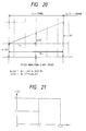
- a frequency response function that is employed for the operation of a spectral envelope is represented as r (x) (0 ⁇ x ⁇ f s /2).
- r (x) the amplitude of a high frequency that is equal to or greater than f1 is increased twice as large.
- This function is employed to transform the spectral envelope value that is integer times of a pitch frequency as follows
- a pitch waveform is w (k) (0 ⁇ k ⁇ N p (f)), and a power normalization coefficient that corresponds to pitch frequency f is C (f).
- pitch waveform w (k) (0 ⁇ k ⁇ N p (f))
- the pitch scale is employed as a scale for representing the tone of speech.
- a frequency response function is represented as is calculated for expression (13), and is calculated for expression (14), and these results are stored in a table.
- pitch period point number N p (s) and power normalization coefficient C (s) that correspond to pitch scale s are stored in a table.
- the waveform generator 9 employs synthesis parameter p [m] (0 ⁇ m ⁇ M), which is obtained from equation (3), and pitch scale s, which is obtained from equation (4), to generate a pitch waveform.
- Fig. 11 is an explanatory diagram for the linking of generated pitch waveforms.
- a speech waveform that is output as synthesized speech by the waveform generator 9 is represented as W (n) (0 ⁇ n).
- the pitch waveforms are linked by the following equations:
- Embodiment 1 the structure and the functional arrangement of a speech synthesis apparatus in Embodiment 7 are shown in the block diagrams in Figs. 25 and 1.
- a synthesis parameter that is employed for the generation of a pitch waveform is defined as p (m) (0 ⁇ m ⁇ M).
- the notation [x] represents an integer that is equal to or smaller than x
- pitch waveform w (k) (0 ⁇ k ⁇ N p (f)) can be generated by the following expression (Fig. 23):
- the pitch scale is employed as a scale for representing the tone of speech.
- the speed of calculation can be increased as follows: with N p as a pitch period point number that corresponds to pitch scale s, is calculated for expression (15), and is calculated for expression (14), and these results are stored in a table.
- pitch period point number N p (s) and power normalization coefficient C (s) that correspond to pitch scale s are stored in a table.
- the waveform generator 9 employs synthesis parameter p [m] (0 ⁇ m ⁇ M), which is obtained from equation (3), and pitch scale s, which is obtained from equation (4), to generate a pitch waveform.
- a waveform generation matrix is calculated from expression (17)
- difference ⁇ s of a pitch scale for one point is read from the pitch scale interpolator 8
- Fig. 11 is an explanatory diagram for the linking of generated pitch waveforms.
- a speech waveform that is output as synthesized speech by the waveform generator 9 is represented as W (n) (0 ⁇ n).
- the pitch waveforms are linked by the following equations:
- Embodiment 1 the structure and the functional arrangement of a speech synthesis apparatus in Embodiment 8 are shown in the block diagrams in Figs. 25 and 1.
- a synthesis parameter that is employed for the generation of a pitch waveform is defined as p (m) (0 ⁇ m ⁇ M).
- the notation [x] represents an integer that is equal to or smaller than x
- pitch waveform w (k) (0 ⁇ k ⁇ [N p (f)/2]) can be generated by the following expression:
- the pitch scale is employed as a scale for representing the tone of speech.
- the speed of calculation can be increased as follows: with N p as a pitch period point number that corresponds to pitch scale s, is calculated for expression (18), and is calculated for expression (19), and these results are stored in a table.
- a waveform generation matrix is In addition, pitch period point number N p (s) and power normalization coefficient C (s) that correspond to pitch scale s are stored in a table.
- the waveform generator 9 employs synthesis parameter p [m] (0 ⁇ m ⁇ M), which is obtained from equation (3), and pitch scale s, which is obtained from equation (4), to generate a pitch waveform.
- a speech waveform that is output as synthesized speech by the waveform generator 9 is represented as W (n) (0 ⁇ n).
- W (n) (0 ⁇ n).
- N j the pitch waveforms of half a period are linked by the following equations:
- Embodiment 1 the structure and the functional arrangement of a speech synthesis apparatus for Embodiment 9 are shown in the block diagrams in Figs. 25 and 1.
- a synthesis parameter that is employed for generation of a pitch waveform is p(m) (0 ⁇ m ⁇ M) and a sampling frequency is f s .
- a pitch frequency of synthesized speech is f
- the notation [x] represents an integer that is equal to or smaller than x.
- the decimal portion of a pitch period point number is represented by linking pitch waveforms that are shifted in phase.
- the number of pitch waveforms that correspond to frequency f is the number of phases n p (f).
- ⁇ 1 as an angle for each point when the pitch period point number corresponds to angle 2 ⁇
- ⁇ 1 2 ⁇ N p (f) .
- the expanded pitch waveform point number is defined as the expanded pitch waveform is w (k) (0 ⁇ k ⁇ N ex (f)), and a power normalization coefficient that corresponds to pitch frequency f is C (f).
- phase index i p (0 ⁇ i p ⁇ n p (f)).
- the pitch waveform point number that corresponds to phase index i p is calculated by the equation of:
- a pitch frequency is altered to f' for the generation of the next pitch waveform
- a value of i' is calculated to satisfy in order to acquire a phase angle that is the closest to ⁇ p
- the pitch scale is employed as a scale for representing the tone of speech.
- the speed of calculation can be increased as follows.
- n p (s) is a phase number that corresponds to pitch scale s ⁇ S (S denotes a set of pitch scales)
- i p (0 ⁇ i p ⁇ n p (s)) is a phase index
- N (s) is an expanded pitch period point number
- N p (s) is a pitch period point number
- P (s, i p ) is a pitch waveform point number
- a phase angle of ⁇ ( s,i p ) 2 ⁇ n p (s) i p , which corresponds to pitch scale s and phase index i p , is stored in the table.
- phase number n p (s), pitch waveform point number P (s, i p ), and power normalization coefficient C (s), each of which corresponds to pitch scale s and phase index i p are stored in the table.
- the phase index that is stored in the internal register is defined as i p
- the phase angle is defined as ⁇ p
- synthesis parameter p (m) (0 ⁇ m ⁇ M)
- pitch scale s which is output by the pitch scale interpolator 8
- the waveform generator 9 then reads from the table pitch waveform point number P (s, i p ) and power normalization coefficient C (s).
- waveform generation matrix WGM (s, i p ) (c km (s, i p )) is read from the table, and a pitch waveform is generated by using
- the waveform generator 9 employs synthesis parameter p [m] (0 ⁇ m ⁇ M), which is obtained by equation (3), and pitch scale s, which is obtained by equation (4) to generate a pitch waveform.
- the waveform generator 9 reads, from the table, pitch waveform point number P (s, i p ) and power normalization coefficient C (s).
- waveform generation matrix WGM (s, i p ) (C km (s, i p )) is read from the table, and a pitch waveform is generated by using
- a pitch waveform is then generated by using
- a speech waveform that is output as synthesized speech by the waveform generator 9 is represented as W (n) (0 ⁇ n).
- the pitch waveforms are linked in the same manner as in Embodiment 1 by using the following equations:
Landscapes
- Engineering & Computer Science (AREA)
- Computational Linguistics (AREA)
- Health & Medical Sciences (AREA)
- Audiology, Speech & Language Pathology (AREA)
- Human Computer Interaction (AREA)
- Physics & Mathematics (AREA)
- Acoustics & Sound (AREA)
- Multimedia (AREA)
- Electrophonic Musical Instruments (AREA)
Abstract
Description
- The present invention relates to a speech synthesis method and a speech synthesis apparatus that employ a system for synthesis by rule.
- Conventional apparatuses for speech synthesis by rule employ, as a method for generating synthesized speech, a synthesis filter system (PARCOR, LESP, or MSLA), a waveform editing system, or a superposition system for an impulse response waveform.
- Speech synthesis that is performed by a synthesis filter system requires many calculations before a speech waveform can be generated, and not only is the load that is placed on the apparatus large, but a long processing time is also required. As for speech synthesis performed by a waveform editing system, since a complicated process must be performed to change the tones of synthesized speech, the load placed on the apparatus is large, and because a complicated waveform editing process must be performed, the quality of the synthesized speech is deteriorated compared with the one before editing.
- Speech synthesis that is performed by an impulse response waveform superposition system deteriorates the quality of sounds in portions where waveforms are superposed.
- By employing the above described conventional techniques, performing a process for generating a speech waveform with a pitch period that is not integer times as large as a sampling cycle is difficult, and therefore, synthesized speech at an exact pitch can not be acquired.
- As with the above described conventional techniques a process for increasing/decreasing sampling speeds and a process for a low-pass filter must be performed for conversion of the sampling frequencies of synthesized speech, the processing that is required is complicated and the number of calculations that must be performed is large.
- When using the above described conventional techniques, parameter operations within frequency ranges can not be performed, and it is difficult for an operator to visualize the operation.
- According to the above described conventional techniques, as parameter operations must be performed to change the timbre of synthesized speech, such processing becomes very complicated.
- According to the above described conventional techniques, all the waveforms for synthesized speech must be generated by the synthesis filter system, the waveform editing system, and the superposition system of impulse response waveforms. As a result, the number of calculations that must be performed is enormous.
- To at least alleviate the above described shortcomings, it is an object of the present invention to provide a speech synthesis method and a speech synthesis apparatus that prevent the deterioration of the quality of synthesized speech and that reduce the number of calculations that are required for generation of a speech waveform.
- It is another object of the present invention to provide a speech synthesis method and a speech synthesis apparatus that provide synthesized speech that has an accurate pitch.
- It is an additional object of the present invention to provide a speech synthesis method and a speech synthesis apparatus that reduce the number of calculations that are required for the conversion of a sampling frequency of a synthesized speech.
- In accordance with the present invention, a speech synthesis apparatus comprises:
generation means for generating pitch waveforms by employing a pitch and a parameter of synthesized speech and for connecting the pitch waveforms to provide a speech waveform; and
generation means for generating an unvoiced waveform using a parameter of synthesized speech and for connecting the unvoiced waveforms to provide a speech waveform that can prevent the deterioration of sound quality for an unvoiced waveform. - A product of a matrix, which is acquired in advance, and a parameter is calculated for each pitch in the process for generating a pitch waveform, so that the number of calculations that are required for the generation of a speech waveform can be reduced.
- A product of a matrix, which is acquired in advance, and a parameter is calculated for the generation of unvoiced speech, so that the number of calculations that are required for the generation of an unvoiced waveforms can be reduced.
- Pitch waveforms, having shifted phases, are generated and linked together to represent a decimal portion of a pitch period point number, so that the exact pitch can be provided for a speech waveform in which is included a decimal portion.
- Since a parameter (impulse response waveform) that is acquired at a specific sampling frequency is employed to generate pitch waveforms for arbitrary sampling frequencies and to link them together, synthesized speech for an arbitrary sampling frequency can be generated by a simple method.
- For the generation of a pitch waveform, a mathematical function that determines a frequency response is employed to multiply a function value integer times a pitch frequency, and a sample value for a spectral envelope, which is obtained by using a parameter, is transformed. Fourier transform is performed on the resultant, transformed sample value to provide a pitch waveform, so that the timbre of synthesized speech can be changed without performing a complicated process, such as a parameter operation.
- Since symmetry of a waveform is used for the generation of a pitch waveform, the number of calculations that are required for the generation of a speech waveform can be reduced.
- According to the present invention, since a power spectrum envelope for speech is employed as a parameter for the generation of a pitch waveform, a speech waveform can be generated by using a parameter in a frequency range and a parameter operation in the frequency range can be performed.
- According to the present invention, for the generation of a pitch waveform, a function that decides a frequency response is employed to multiply a function value integer times a pitch frequency, and a sample value of a spectral envelope that is acquired by a parameter is transformed. Then, a Fourier transform is performed on the transformed sample value to generate a pitch waveform, so that the timbre of the synthesized speech can be altered without parameter operations.
- A number of embodiments of the invention will now be described, by way of example only.
- Fig. 1 is a block diagram illustrating the arrangement of functions of components in a speech synthesis apparatus according to one embodiment of the present invention;
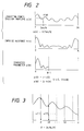
- Fig. 2 is an explanatory diagram for a synthesis parameter according to the embodiment of the present invention;
- Fig. 3 is an explanatory diagram for a spectral envelope according to the embodiment of the present invention;
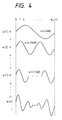
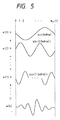
- Fig. 4 is an explanatory diagram for the superposition of sine waves;
- Fig. 5 is an explanatory diagram for the superposition of sine waves;
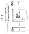
- Fig. 6 is an explanatory diagram for the generation of a pitch waveform;
- Fig. 7 is a flowchart showing a speech waveform generating process;
- Fig. 8 is a diagram showing the data structure of 1 frame of parameters;
- Fig. 9 is an explanatory diagram for interpolation of synthesis parameters;
- Fig. 10 is an explanatory diagram for interpolation of pitch scales;
- Fig. 11 is an explanatory diagram for linking waveforms;
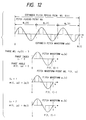
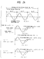
- Fig. 12 is an explanatory diagram for a pitch waveform;
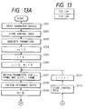
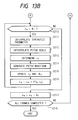
- Fig. 13 is comprised of Figs. 13A and 13B showing flowcharts of a speech waveform generation process;
- Fig. 14 is a block diagram illustrating the functional arrangement of a speech synthesis apparatus according to another embodiment;
- Fig. 15 is a flowchart showing a speech waveform generation process;
- Fig. 16 is a diagram showing the data structure of 1 frame of parameters;
- Fig. 17 is an explanatory diagram for a synthesis parameter;
- Fig. 18 is an explanatory diagram for generation of a pitch waveform;
- Fig. 19 is a diagram illustrating the data structure of 1 frame of parameters;
- Fig. 20 is an explanatory diagram for interpolation of synthesis parameters;
- Fig. 21 is an explanatory diagram for a mathematical function of a frequency response;
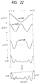
- Fig. 22 is an explanatory diagram for the superposition of cosine waves;
- Fig. 23 is an explanatory diagram for the superposition of cosine waves;
- Fig. 24 is an explanatory diagram for a pitch waveform; and
- Fig. 25 is a block diagram illustrating the arrangement of a speech synthesis apparatus according to the embodiment of the present invention.
- Fig. 25 is a block diagram illustrating the arrangement of a speech synthesis apparatus according to one embodiment of the present invention.
- A keyboard (KB) 101 is employed to input text for synthesized speech and to input control commands, etc.. A
pointing device 102 is employed to input a desired position on the display screen of adisplay 108; by positioning a pointing icon with this device, desired control commands, etc., can be input. A central processing unit (CPU) 103 controls various processes, in the embodiment that will be described later, that are executed by the apparatus of the present invention, and performs processing by executing a control program that is stored in a read only memory (ROM) 105. A communication interface (I/F) 104 is employed to control the transmission and the reception of data across various communication networks. TheROM 105 is employed for storing a control program for a process that is shown in a flowchart for this embodiment. A random access memory (RAM) 106 is employed as a means for storing data that are generated by various processes in the embodiment. Aloudspeaker 107 is used to output sounds, such as synthesized speech and messages for an operator. Thedisplay 108, an apparatus such as an LCD or a CRT, is employed to display text that are input at the keyboard and data that are being processed. Abus 109 is used to transfer data and commands between the individual components. - Fig. 1 is a block diagram illustrating the functional arrangement of a synthesis apparatus according to
Embodiment 1 of the present invention. These functions are executed under the control of theCPU 103 in Fig. 25. A characterseries input section 1 inputs a character series for a speech that is to be synthesized. When speech to be synthesized is for example, a character series of phonetic text, such as "AIUEO", is input. Aside from phonetic text, character series that are input by the character
series input section 1 indicate control sequences that are for determining utterance speeds and pitches. The characterseries input section 1 determines whether or not an input character series is phonetic text or a control sequence. Character series that are determined as control sequences by the characterseries input section 1, and control data for utterance speeds and pitches that are input via a user interface are transmitted to acontrol data memory 2 and stored in the internal register of thecontrol data memory 2. For generation of a parameter series, aparameter generator 3 reads a parameter series, which is stored in advance from theROM 105 in consonance with a character series that is input by the characterseries input section 1 and that is determined to be phonetic text. A parameter of a frame that is to be processed is extracted from the parameter series that is generated by theparameter generator 3 and is stored in the internal register of aparameter memory 4. Aframe time setter 5 calculates time length Ni for each frame by employing control data that concern utterance speeds and that are stored in thecontrol data memory 2, and utterance speed coefficient K (a parameter used for determining a frame time length in consonance with utterance speed), which is stored in theparameter memory 4. A waveformpoint number memory 6 is employed to store in its internal register acquired waveform point number nW for one frame. A synthesis parameter interpolator 7 interpolates synthesis parameters, which are stored in theparameter memory 4, by using frame time length Ni, which is set by theframe time setter 5, and waveform point number nW, which is stored in the waveformpoint number memory 6. Apitch scale interpolator 8 interpolates pitch scales, which are stored in theparameter memory 4, by using frame time length Ni, which is set by theframe time setter 5, and waveform point number nw, which is stored in the waveformpoint number memory 6. Awaveform generator 9 generates a pitch waveform by using a synthesis parameter, which has been interpolated by the synthesis parameter interpolator 7, and a pitch scale, which has been interpolated by thepitch scale interpolator 8, and links the pitch waveforms to output synthesized speech. - Processing of the
waveform generator 9 for generating a pitch waveform will now be described while referring to Figs. 2 through 6. - A synthesis parameter that is employed for the generation of a pitch waveform will be explained. In Fig. 2, with the power of the Fourier transform is denoted by N, and the power of a synthesis parameter is denoted by M, N and M satisfy N ≧ 2M. Suppose that a logarithm power spectrum envelope for speech is

The logarithm power spectrum envelope is substituted in an exponentional function to return the envelope to a linear form, and a reverse Fourier transform is performed on the resultant envelope. The acquired impulse response is
- Synthesis parameter

is acquired by doubling the ratio of a value of the power of 0 of the impulse response and a value of the power of 1 and the following number of the impulse response. In other words, with r ≠ 0,

- With a sampling frequency of fs, a sampling period is

When a pitch frequency of synthesized speech is f, a pitch period is
and the pitch period point number is
[x] represents an integer that is equal to or smaller than x, and the pitch period point number, which is quantized by using an integer, is expressed as
When the pitch period corresponds to angle 2π, an angle for each point is represented by ϑ,
The value of a spectral envelope that is integer times as large as the pitch frequency is expressed as follows (Fig. 3):
A pitch waveform is
and a power normalization coefficient that corresponds to pitch frequency f is
When a pitch frequency with which C (f) = 1.0 is established is f₀, the following equation provides C(f):
- Sine waves that are integer times of a fundamental frequency are superposed, and by the following expression, pitch waveform w (k) (0 ≦ k < Np (f)) can be generated (Fig. 4):

- Or, the sine waves are superposed with half of a phase of the pitch period being shifted, and by the following expression, pitch waveform w (k) (0 ≦ k < Np (f)) can be generated (Fig. 5):

- The pitch scale is employed as a scale for representing the tone of speech. Instead of calculating expressions (1) and (2), the speed of calculation can be increased as follows: with Np as a pitch period point number that corresponds to pitch scale s,


is calculated for expression (1), and
is calculated for expression (2), and these results are stored in a table. A waveform generation matrix is
In addition, pitch period point number Np (s) and power normalization coefficient C (s) that correspond to pitch scale s are stored in a table. - By employing, as input data, the synthesis parameter p (m) (0 ≦ m < M), which is output by the synthesis parameter interpolator 7, and pitch scale s, which is output by the
pitch scale interpolator 8, from the table thewaveform generator 9 reads pitch period point number Np (s), power normalization coefficient C (s), and waveform generation matrix WGM (s) = (ckm (s)), and generates a pitch waveform (Fig. 6) by using the following equation:
- The process, beginning with the input of phonetic text and continuing until the generation of a pitch waveform, will now be described while referring to the flowchart in Fig. 7.
- At step S1, phonetic text is input by the character
series input section 1. - At step S2, control data (utterance speed, pitch of speech, etc.) that are externally input, and control data for the input phonetic text are stored in the
control data memory 2. - At step S3, the
parameter generator 3 generates a parameter series for the phonetic text that has been input by the characterseries input section 1. - A data structure example for one frame of parameters that are generated at step S3 is shown in Fig. 8.
- At step S4, the internal register of the waveform
point number memory 6 is set to 0. The waveform point number is represented by nW as follows:
- At step S5, parameter series counter i is initialized to 0.
- At step S6, parameters for the ith frame and the (i+1)th frame are fetched from the
parameter generator 3 to the internal register of theparameter memory 4. - At step S7, utterance speed is fetched from the
control data memory 2 to theframe time setter 5. - At step S8, the
frame time setter 5 employs utterance speed coefficients for the parameters, which have been fetched to theparameter memory 4, and utterance speed that has been fetched from thecontrol data memory 2 to set frame time length Ni. - At step S9, a check is performed to ascertain whether or not waveform point number nW is smaller than frame time length Ni in order to determine whether or not the process for the ith frame has been completed. When nW ≧ Ni, it is assumed that the process for the ith frame has been completed, and program control advances to step S14. When nW < Ni, it is assumed that the process for the ith frame is in the process of being performed and program control moves to step S10 where the process is continued.
- At step S10, the synthesis parameter interpolator 7 employs the synthesis parameter, which is stored in the
parameter memory 4, the frame time length, which is set by theframe time setter 5, and the waveform point number, which is stored in the waveformpoint number memory 6, to perform interpolation for the synthesis parameter. Fig. 9 is an explanatory diagram for the interpolation of the synthesis parameter. A synthesis parameter for the ith frame is denoted by pi [m] (0 ≦ m < M), a synthesis parameter for the (i+1)th frame is denoted by Pi+1 [m] (0 ≦ m < M), and the time length for the ith frame is denoted by Ni point. A difference Δp [m] (0 ≦ m < M) of a synthesis parameter for each point is
Then, synthesis parameter p [m] (0 ≦ m < M) is updated each time a pitch waveform is generated. The process
is performed at the starting point for a pitch waveform. - At step S11, the
pitch scale interpolator 8 employs the pitch scale, which is stored in theparameter memory 4, the frame time length, which is set by theframe time setter 5, and the waveform point number, which is stored in the waveformpoint number memory 6, to interpolate the pitch scale. Fig. 10 is an explanatory diagram for the interpolation of pitch scales. Suppose that a pitch scale for the ith frame is si, a pitch scale of the (i+1)th frame is si+1, and the Ni point is a frame time length for the ith frame. Difference Δs of a pitch scale for each point is represented as
Then, pitch scale s is updated each time a pitch waveform is generated. The process
is performed at the starting point for a pitch waveform. - At step S12, the
waveform generator 9 employs synthesis parameter p [m] (0 ≦ m < M), which is obtained from equation (3), and pitch scale s, which is obtained from equation (4), to generate a pitch waveform. Thewaveform generator 9 reads, from the table, pitch period point number Np (s), power normalization coefficient C (s), and waveform generation matrix WGM (s) = (Ckm (s)) (0 ≦ k < Np (s), 0 ≦ m < M), which correspond to pitch scale s, and generates a pitch waveform with the following expression:
- Fig. 11 is an explanatory diagram for the linking of generated pitch waveforms. A speech waveform that is output as synthesized speech by the
waveform generator 9 is represented as
The pitch waveforms are linked by the following equations:
- At step S13, in the waveform
point number memory 6, the waveform point number nW is updated by
program control returns to step S9, and the processing is repeated. - When, at step S9, nW ≧ Ni, program control goes to step S14.
- At step S14, the waveform point number nW is initialized as

- At step S15, a check is performed to determine whether or not the process for all the frames has been completed. When the process is not yet completed, program control goes to step S16.
- At step S16, the control data (utterance speed, pitch of speech, etc.) that are input externally are stored in the
control data memory 2. At step S17, parameter series counter i is updated as
Program control then returns to step S6 and the processing is repeated. - When, at step S15, the process for all the frames has been completed, the processing is thereafter terminated.
- As they are for
Embodiment 1, the structure and the functional arrangement of a speech synthesis apparatus according toEmbodiment 2 are shown in the block diagrams in Figs. 25 and 1. - In this embodiment, an explanation will be given for an example where pitch waveforms whose phases are shifted are generated and linked in order to represent the decimal portion of a pitch period point number.
- The processing by the
waveform generator 9 for the generation of a pitch waveform will be described while referring to Fig. 12. - Suppose that a synthesis parameter that is employed for generation of a pitch waveform is

and a sampling frequency is fs. A sampling period then is
When a pitch frequency of synthesized speech is f, a pitch period is
and the pitch period point number is
- The notation [x] represents an integer that is equal to or smaller than x.
- The decimal portion of a pitch period point number is represented by linking pitch waveforms that are shifted in phase. The number of pitch waveforms that correspond to frequency f is the number of phases

An example in Fig. 12 is a pitch waveform with np (f) = 3. Further, an expanded pitch period point number is expressed as
and a pitch period point number is quantized to obtain
With ϑ₁ as an angle for each point when the pitch period point number corresponds to angle 2π,
The value of a spectral envelope that is integer times as large as the pitch frequency is expressed as follows:
With ϑ₂ as an angle for each point when the expanded pitch period point number corresponds to 2π,
The expanded pitch waveform is
and a power normalization coefficient that corresponds to pitch frequency f is
When a pitch frequency with which C(f) = 1.0 is established is f₀, the following equation provides C(f):
- Sine waves that are integer times of a pitch frequency are superposed, and expanded pitch waveform w (k) (0 ≦ k < N (f)) can be generated by using the following expression:

- Or, the sine waves are superposed with half a phase of the pitch period being shifted, and expanded pitch waveform w (k) (0 ≦ k < N (f)) can be generated by using the following expression:

- Suppose that a phase index is

A phase angle that corresponds to pitch frequency f and phase index ip is defined as:
The statement a mod b is defined as representing the remainder following the division of a by b as in
The pitch waveform point number that corresponds to phase index ip is calculated by the equation of:
A pitch waveform that corresponds to phase index ip is defined as
Then, the phase index is updated to
and the updated phase index is employed to calculate a phase angle to establish
When a pitch frequency is altered to f' for the generation of the next pitch waveform, a value of i' is calculated to satisfy
in order to acquire a phase angle that is the closest to φp, and ip is determined as
- The pitch scale is employed as a scale for representing the tone of speech. Instead of calculating expressions (5) and (6), the speed of calculation can be increased as follows. When np (s) is a phase number that corresponds to pitch scale s ε S (S denotes a set of pitch scales), ip (0 ≦ ip < np (s)) is a phase index, N (s) is an expanded pitch period point number, Np (s) is a pitch period point number, and P (s, ip) is a pitch waveform point number, with the following equation


for equation (5),
is calculated, and for equation (6),
is calculated, and the obtained results are stored in the table. A pitch scale generation matrix is defined as
A phase angle of
which corresponds to pitch scale s and phase index ip, is stored in the table. With respect to pitch scale s and phase angle φp (ε { φ (s, ip) | s ε S, 0 ≦ i < np (s)}), such a relationship that provides io to establish
is defined as
and is stored in the table. Further, phase number np (s), pitch waveform point number p (s, ip), and power normalization coefficient C (s), each of which corresponds to pitch scale s and phase index ip, are stored in the table. - In the
waveform generator 9, the phase index that is stored in the internal register is defined as ip, the phase angle is defined as φp, and synthesis parameter p (m) (0 ≦ m < M), which is output by the synthesis parameter interpolator 7, and pitch scale s, which is output by thepitch scale interpolator 8, are employed as input data, so that the phase index can be determined by the following equation:
Thewaveform generator 9 then reads from the table pitch waveform point number P (s, ip), power normalization coefficient C (s) and waveform generation matrix WGM (s, ip) = (ckm (s, ip)), and generates a pitch waveform by using the expression
After the pitch waveform has been generated, the phase index is updated as follows:
and the updated phase index is employed to update the phase angle as follows:
- The above described process will now be described while referring to the flowchart in Figs. 13A and 13B.
- At step S201, phonetic text is input by the character
series input section 1. - At step S202, control data (utterance speed, pitch of speech, etc.) that are externally input and control data for the input phonetic text are stored in the
control data memory 2. - At step S203, the
parameter generator 3 generates a parameter series with the phonetic text that has been input by the characterseries input section 1. - The data structure for one frame of parameters that are generated at step S203 is the same as that of
Embodiment 1 and is shown in Fig. 8. - At step S204, the internal register of the waveform
point number memory 6 is set to 0. The waveform point number is represented by nW as follows:
- At step S205, parameter series counter i is initialized to 0.
- At step S206, phase index ip is initialized to 0, and phase angle φp is initialized to 0.
- At step S207, parameters for the ith frame and the (i+1)th frame are fetched from the
parameter generator 3 and stored in theparameter memory 4. - At step S208, utterance speed data is fetched from the
control data memory 2 for use by theframe time setter 5. - At step S209, the
frame time setter 5 employs utterance speed coefficients for the parameters, which have been fetched into theparameter memory 4, and utterance speed data that have been fetched from thecontrol data memory 2 to set frame time length Ni. - At step S210, a check is performed to determine whether or not waveform point number nW is smaller than frame time length Ni. When nW ≧ Ni, program control advances to step S217. When nW < Ni, program control moves to step S211 where the process is continued.
- At step S211, the synthesis parameter interpolator 7 employs the synthesis parameter, which is stored in the
parameter memory 4, the frame time length, which is set by theframe time setter 5, and the waveform point number, which is stored in the waveformpoint number memory 6, to perform interpolation for the synthesis parameter. The parameter interpolation is performed in the same manner as at step S10 inEmbodiment 1. - At step S212, the
pitch scale interpolator 8 employs the pitch scale, which is stored in theparameter memory 4, the frame time length, which is set by theframe time setter 5, and the waveform point number, which is stored in the waveformpoint number memory 6 to interpolate the pitch scale. The pitch scale interpolation is performed in the same manner as at step S11 inEmbodiment 1. - At step S213, a phase index is determined by

which is established by using pitch scale s and phase angle φp that are acquired by equation (4). - At step S214, the
waveform generator 9 employs synthesis parameter p [m] (0 ≦ m < M), which is obtained by equation (3), and pitch scale s, which is obtained by equation (4) to generate a pitch waveform. Thewaveform generator 9 reads, from the table, pitch waveform point number P (s, ip), power normalization coefficient C (s), and waveform generation matrix WGM (s, ip) = (ckm (s, ip)) (0 ≦ k < P (s, ip), 0 ≦ m < M), which correspond to pitch scale s, and generates a pitch waveform by the following expression:
- A speech waveform that is output as synthesized speech by the
waveform generator 9 is defined as
The pitch waveforms are linked in the same manner as inEmbodiment 1. With the time length for the jth frame defined as Nj,
- At step S215, the phase index is updated as described below:

and the updated phase index is employed to update the phase angle as follows:
- At step S216, in the waveform
point number memory 6, the waveform point number nW is updated with
program control returns to step S210, and the processing is repeated. - When, at step S210, nW ≧ Ni, program control goes to step S217.
- At step S217, the waveform point number nw is initialized as

- At step S218, a check is performed to determine whether or not the process for all the frames has been completed. When the process has not yet been completed, program control goes to step S219.
- At step S219, the control data (utterance speed, pitch of speech, etc.) that are input externally are stored in the
control data memory 2. At step S220, parameter series counter i is updated as
Program control then returns to step S207 and the processing is repeated. - When, at step S218, the process for all the frames has been completed, the processing is thereafter terminated.
- In addition to the method for generating a pitch waveform described in
Embodiment 1, generation of an unvoiced waveform will now be described in this embodiment. - Fig. 14 is a block diagram illustrating the functional arrangement of a speech synthesis apparatus in
Embodiment 3. The individual functions are performed under the control of theCPU 103 in Fig. 25. A characterseries input section 301 inputs a character series of speech to be synthesized. When speech to be synthesized is, for example, "voice", a character series of such phonetic text as "OnSEI" is input. In addition to a phonetic text, the character series that is input by the characterseries input section 1 sometimes includes a character series that constitutes a control sequence for setting utterance speed and a speech pitch. The characterseries input section 301 determines whether or not the input character series is phonetic text or a control sequence. In acontrol data memory 302 is an internal register, where are stored a character series, which is determined as a control sequence by the characterseries input section 301 and forwarded thereto, and control data, such as utterance speed and speech pitch, which are input by a under interface. Aparameter generator 303 reads, from theROM 105, a parameter series that is stored in advance in consonance with a character series, which has been input and has been determined to be phonetic text by the characterseries input section 301, and generates a parameter series. Parameters for a frame that is to be processed are extracted from the parameter series that is generated by theparameter generator 303, and are stored in the internal register of aparameter memory 304. Aframe time setter 305 employs control data that concern utterance speed, which is stored in thecontrol data memory 302, and utterance speed coefficient K (parameter employed for determining a frame time length in consonance with utterance speed), which is stored in theparameter memory 304, and calculates time length Ni for each frame. A waveformpoint number memory 306 has an internal register wherein is stored acquired waveform point number nw for each frame. Asynthesis parameter interpolator 307 interpolates synthesis parameters that are stored in theparameter memory 304 by using frame time length Ni, which is set by the frametime length setter 305, and waveform point number nw, which is stored in the waveformpoint number memory 306. Apitch scale interpolator 308 interpolates a pitch scale that is stored in theparameter memory 304 by using frame time length ni, which is set by the frametime length setter 305, and waveform point number nw, which is stored in the waveformpoint number memory 306. Awaveform generator 309 generates pitch waveforms by using a synthesis parameter, which is obtained as a result of the interpolation by thesynthesis parameter interpolator 307, and a pitch scale, which is obtained as a result of the interpolation by thepitch scale interpolator 308, and links together the pitch waveforms, so that synthesized speech is output. In addition, thewaveform generator 309 generates unvoiced waveforms by employing a synthesis parameter that is output by thesynthesis parameter interpolator 307, and links the unvoiced waveforms together to output synthesized speech. - The processing performed by the
waveform generator 309 to generate a pitch waveform is the same as that performed by thewaveform generator 9 inEmbodiment 1. - In this embodiment, in addition to pitch waveform generation that is performed by the
waveform generator 9, the generation of an unvoiced waveform will now be described. - Suppose that a synthesis parameter that is employed for generation of an unvoiced waveform is

and a sampling frequency is fs. A sampling period then is
A pitch frequency of a sine wave that is employed for the generation of an unvoiced waveform is denoted by f, which is set to a frequency that is lower than an audio frequency band. - The notation [x] represents an integer that is equal to or smaller than x.
- The pitch period point number that corresponds to pitch frequency f is

- An unvoiced waveform point number is defined as

With ϑ₁ as an angle for each point when the unvoiced waveform point number corresponds to angle 2π,
The value of a spectral envelope that is integer times as large as the pitch frequency f is expressed as follows:
The expanded unvoiced waveform is
and a power normalization coefficient that corresponds to pitch frequency f is
When a pitch frequency with which C (f) = 1.0 is established is f₀, the following equation provides C (f):
A power normalization coefficient that is used for the generation of an unvoiced waveform is defined as
- Sine waves that are integer times as large as a pitch frequency are superposed while their phases are shifted at random to provide an unvoiced waveform. A shift in phases is denoted by α₁ (1 ≦ 1 ≦ [Nuv/2]). The expression α₁ is set to a random value such that it satisfies

Then, unvoiced waveform wuv (k) (0 ≦ k < Nuv) can be generated as follows:
Instead of calculating equation (7), the speed of computation can be increased as follows. With an unvoiced waveform index as

is calculated and stored in the table. An unvoiced waveform generation matrix is defined as
In addition, pitch period point number Nuv and power normalization coefficient Cuv are stored in the table. - In the
waveform generator 309, with an unvoiced waveform index that is stored in the internal register being denoted by iuv, and synthesis parameter p (m) (0 ≦ m < M), which is output by the synthesis parameter interpolator 7, being employed as input data, unvoiced waveform generation matrix UVWGM (iuv) = (c (iuv, m)) is read from the table, and an unvoiced generator is generated for one point by equation
After the unvoiced waveform has been generated, pitch period point number Nuv is read from the table, and unvoiced waveform index iuv is updated as
Waveform point number nW that is stored in the waveformpoint number memory 306 is also updated below
- The above described process will now be described while referring to the flowchart in Fig. 15.
- At step S301, phonetic text is input by the character
series input section 301. - At step S302, control data (utterance speed, pitch of speech, etc.) that are externally input and control data for the input phonetic text are stored in the
control data memory 302. - At step S303, the
parameter generator 303 generates a parameter series with the phonetic text that has been input by the characterseries input section 301. - The data structure for one frame of parameters that are generated at step S303 is shown in Fig. 16.
- At step S304, the internal register of the waveform
point number memory 306 is set to 0. The waveform point number is represented by nW as follows:
- At step S305, parameter series counter i is initialized to 0.
- At step S306, unvoiced waveform index iuv is initialized to 0.
- At step S307, parameters for the ith frame and the (i+1)th frame are fetched from the
parameter generator 303 into theparameter memory 304. - At step S308, utterance speed data are fetched from the
control data memory 302 for use by theframe time setter 305. - At step S309, the
frame time setter 305 employs utterance speed coefficients for the parameters, which have been fetched and stored in theparameter memory 304, and utterance speed data that have been fetched from thecontrol data memory 302 to set frame time length Ni. - At step S310, voiced or unvoiced parameter information that is fetched and stored in the
parameter memory 304 is employed to determine whether or not the parameter of the ith frame is for an unvoiced waveform. If the parameter for that frame is for an unvoiced waveform, program control advances to step S311. If the parameter is for a voiced waveform, program control moves to step S317. - At step S311, a check is performed to determine whether or not waveform point number nW is smaller than frame time length Ni. When nW ≧ Ni, program control advances to step S315. When nW < Ni, program control moves to step S312 where the process is continued.
- At step S312, the
waveform generator 9 employs a synthesis parameter for the ith frame, pi [m] (0 ≦ m < M), which is input by thesynthesis parameter interpolator 307, to generate an unvoiced waveform. Thewaveform generator 9 reads power normalization coefficient C (s) from the table, and also reads from the table waveform generation matrix UVWGM (iuv) = (c (iuv, m)) (0 ≦ m < M), which corresponds to unvoiced waveform index iuv. Then, an unvoiced waveform is generated with the following equation:
- A speech waveform that is output as synthesized speech by the
waveform generator 309 is defined as
The unvoiced waveforms are linked with the time length for the jth frame being defined as Nj from the equation
- At step S313, unvoiced waveform point number Nuv is read from the table, and an unvoiced waveform index is updated as described below:

- At step S314, in the waveform
point number memory 306, the waveform point number nW is updated by
program control returns to step S311, and the processing is repeated. - When, at step S310, information indicates an unvoiced parameter, program control moves to step S317, where pitch waveforms for the ith frame are generated and are linked together. The processing at this step is the same as that which is performed at steps S9 through S13 in
Embodiment 1. - When, at step S311, nW ≧ Ni, program control goes to step S315, and the waveform point number nW is initialized as

- At step S316, a check is performed to determine whether or not the process for all the frames has been completed. When the process has not yet been completed, program control goes to step S318.
- At step S318, the control data (utterance speed, pitch of speech, etc.) that are input externally are stored in the
control data memory 302. At step S319, parameter series counter i is updated as
Program control then returns to step S307 and the processing is repeated. - When, at step S316, the process for all the frames has been completed, the processing is thereafter terminated.
- In this embodiment, an explanation will be given for an example where processing can be performed at a sampling frequency that differs at the analyzing process and at the synthesizing process.
- The structure and the functional arrangement of a speech synthesis apparatus according to
Embodiment 4 are shown in the block diagrams in Figs. 25 and 1, as forEmbodiment 1. - The processing by the
waveform generator 9 for the generation of a pitch waveform will be described. - Suppose that a synthesis parameter that is employed for generation of a pitch waveform is

and a sampling frequency, for an impulse response waveform, that is a synthesis parameter is defined as an analysis sampling frequency of fs1. An analysis sampling period then is
When a pitch frequency of synthesized speech is f, a pitch period is
and the analysis pitch period point number is
- The expression [x] represents an integer that is equal to or smaller than x, and the analysis pitch period point is quantized so that it becomes

- When a sampling frequency for synthesized speech is denoted by a synthesis sampling frequency of fs2, the synthesis pitch period point number is

which when quantized becomes
- With ϑ₁ as an angle for one point when the analysis pitch period point number corresponds to angle 2π,

The value of a spectral envelope that is integer times as large as the pitch frequency is expressed as follows:
With ϑ₂ as an angle for one point when the synthesis pitch period point number corresponds to 2π,
The pitch waveform is
and a power normalization coefficient that corresponds to pitch frequency f is
When a pitch frequency with which C(f) = 1.0 is established is f₀, the following equation provides C(f):
- Sine waves that are integer times as large as a pitch frequency are superposed, and pitch waveform w (k) (0 ≦ k < Np2 (f)) can be generated by using the following expression:

- Or, the sine waves are superposed with half of a phase of the pitch period being shifted, and pitch waveform w (k) (0 ≦ k < Np2 (f)) can be generated by the following expression:

- The pitch scale is employed as a scale for representing the tone of speech. Instead of calculating expressions (8) and (9), the speed of calculation can be increased as follows. When Np1 (s) is a phase number that corresponds to pitch scale s ε S (S denotes a set of pitch scales) and Np2 (s) is an synthesis pitch period point number, with the following equations


for equation (8),
is calculated, and for equation (9),
is calculated, and these results are stored in the table. A pitch scale generation matrix is defined as
In addition, synthesis pitch period point number Np2 (s) and power normalization coefficient C(s), both of which correspond to pitch scale s, are stored in the table. - In the
waveform generator 9, synthesis parameter p (m) (0 ≦ m < M), which is output by the synthesis parameter interpolator 7, and pitch scale s, which is output by thepitch scale interpolator 8, are employed as input data, and synthesis pitch waveform point number Np2 (s), power normalization coefficient C (s), and waveform generation matrix WGM (s) = (ckm (s)) are read from the table. A pitch waveform is then generated by equation
- The above described process will now be described while referring to the flowchart in Fig. 7.
- The procedures performed at steps S1 through S11 in this embodiment are the same as those performed in
Embodiment 1. - The process at step S12 for pitch waveform generation in this embodiment will now be described. The
waveform generator 9 employs synthesis parameter p [m] (0 ≦ m < M), which is obtained by using equation (3), and pitch scale s, which is obtained by using equation (4), to generate a pitch waveform. Thewaveform generator 9 reads, from the table, synthesis pitch waveform point number Np2 (s), power normalization coefficient C (s), and waveform generation matrix WGM (s) = (ckm (s)) (0 ≦ k < Np2 (s), 0 ≦ m < M), all of which correspond to pitch scale s, and generates a pitch waveform by using the following equation:
- A speech waveform that is output as synthesized speech by the
waveform generator 9 is defined as
The pitch waveforms are linked together with the time length for the jth frame, which is defined as Nj, so that
- At step S13, in the waveform
point number memory 6, the waveform point number nW is updated to
- The procedures performed at steps S14 through S17 in this embodiment are the same as those performed in
Embodiment 1. - In this embodiment, an example where a pitch waveform is generated by a power spectrum envelope to enable parameter operations, within a frequency range, that employs the power spectral envelope.
- As they are for
Embodiment 1, the structure and the functional arrangement of a speech synthesis apparatus inEmbodiment 5 are shown in Figs. 25 and 1. - Processing of the
waveform generator 9 for generating a pitch waveform will now be described. - A synthesis parameter that is employed for the generation of a pitch waveform will be explained. In Fig. 17, with the power of the Fourier transform being denoted by N, and the power of a synthesis parameter being denoted by M, N and M satisfy N ≧ 2M. Suppose that a logarithm power spectrum envelope for speech is

The logarithm power spectrum envelope is substituted into an exponentional function to return the envelope to a linear form, and a reverse Fourier transform is performed on the resultant envelope. The acquired impulse response is
- Impulse response waveform

which is employed for the generation of a pitch waveform, is acquired by relatively doubling the ratio of a value of the power of 0 of the impulse response and a value of the power of 1 and the following number of the impulse response. In other words, with r ≠ 0,

- When a synthesis parameter is defined as


When the following equation is established
then,
- With a sampling frequency of fs, a sampling period is

When a pitch frequency of synthesized speech is f, a pitch period is
and the pitch period point number is
The expression [x] represents an integer that is equal to or smaller than x, and the pitch period point number, which is quantized by using an integer, is expressed as
When the pitch period corresponds to angle 2π, an angle for each point is represented by ϑ,
The value of a spectral envelope that is integer times as large as the pitch frequency is expressed as follows:
A pitch waveform is
and a power normalization coefficient that corresponds to pitch frequency f is
When a pitch frequency with which C (f) = 1.0 is established is f₀, the following equation provides C(f):
- Sine waves that are integer times as large as a fundamental frequency are superposed, and pitch waveform w (k) (0 ≦ k < Np (f)) is generated as follows:

- Or, the sine waves are superposed with half of a phase of the pitch period being shifted, and pitch waveform w (k) (0 ≦ k < Np (f)) is generated as follows:

- The pitch scale is employed as a scale for representing the tone of speech. Instead of calculating expressions (10) and (11), the speed of calculation can be increased as follows: with Np (s) as a pitch period point number that corresponds to pitch scale s,


is calculated for expression (10), and
is calculated for expression (11), and these results are stored in a table. A waveform generation matrix is
In addition, pitch period point number Np (s) and power normalization coefficient C (s) that correspond to pitch scale s are stored in a table. - By employing, as input data, the synthesis parameter p (n) (0 ≦ n < N), which is output by the synthesis parameter interpolator 7, and pitch scale s, which is output by the
pitch scale interpolator 8, from the table thewaveform generator 9 reads pitch period point number Np (s), power normalization coefficient C (s), and waveform generation matrix WGM (s) = (ckn (s)), and generates a pitch waveform (Fig. 18) by using the following equation:
- The above described process will now be described while referring to the flowchart in Fig. 7.
- The procedures performed at steps S1, S2, and S3 are the same as those that are performed in
Embodiment 1. - The data structure of one frame of parameters that is generated at step S3 is shown in Fig. 19.
- The procedures at steps S4 through S9 are the same as those in
Embodiment 1. - At step S10, the synthesis parameter interpolator 7 employs the synthesis parameter, which is stored in the
parameter memory 4, the frame time length, which is set by theframe time setter 5, and the waveform point number, which is stored in the waveformpoint number memory 6, to perform interpolation for the synthesis parameter. Fig. 20 is an explanatory diagram for the interpolation of the synthesis parameter. A synthesis parameter for the ith frame is denoted by pi [n] (0 ≦ n < N), a synthesis parameter for the (i+1)th frame is denoted by pi+1 [n] (0 ≦ n < N), and the time length for the ith frame is denoted by Ni point. A difference Δp [n] (0 ≦ n < N) of a synthesis parameter for each point is
Then, synthesis parameter p [n] (0 ≦ n < N) is updated each time a pitch waveform is generated. The process
is performed at the starting point for a pitch waveform. - The procedure at step S11 is the same as that in
Embodiment 1. - At step S12, the
waveform generator 9 employs synthesis parameter p [n] (0 ≦ n < N), which is obtained from equation (12), and pitch scale s, which is obtained from equation (4), to generate a pitch waveform. Thewaveform generator 9 reads, from the table, pitch period point number Np (s), power normalization coefficient C (s), and waveform generation matrix WGM (s) = (ckn (s)) (0 ≦ k < Np (s), 0 ≦ n < N), which correspond to pitch scale s, and generates a pitch waveform by using the following expression:
- Fig. 11 is an explanatory diagram for the linking of generated pitch waveforms. A speech waveform that is output as synthesized speech by the
waveform generator 9 is represented as
The pitch waveforms are linked by the following equations:

The procedures performed at steps S13 through S17 are the same as those performedEmbodiment 1. - In this embodiment, an example where a function that determines a frequency response is employed to transform a spectral envelope will be described.
- As they are for
Embodiment 1, the structure and the functional arrangement of a speech synthesis apparatus inEmbodiment 6 are shown in the block diagrams in Figs. 25 and 1. - The pitch waveform generation performed by the
waveform generator 9 will now be explained. - A synthesis parameter that is employed for the generation of a pitch waveform is defined as

With a sampling frequency of fs, a sampling period is
When a pitch frequency of synthesized speech is f, a pitch period is
and the pitch period point number is
The notation [x] represents an integer that is equal to or smaller than x, and the pitch period point number, which is quantized by using an integer, is expressed as
When the pitch period corresponds to angle 2π, an angle for each point is represented by ϑ,
The value of a spectral envelope that is integer times as large as the pitch frequency is expressed as follows:
- A frequency response function that is employed for the operation of a spectral envelope is represented as

In an example in Fig. 21, the amplitude of a high frequency that is equal to or greater than f₁ is increased twice as large. By changing r (x), the spectral envelope can be operated. This function is employed to transform the spectral envelope value that is integer times of a pitch frequency as follows
A pitch waveform is
and a power normalization coefficient that corresponds to pitch frequency f is
When a pitch frequency with which C (f) = 1.0 is established is f₀, the following equation provides C(f):
- Sine waves that are integer times as large as a fundamental frequency are superposed, and pitch waveform w (k) (0 ≦ k < Np (f)) can be generated by using the following expression:

- Or, the sine-waves are superposed with half a phase of the pitch period being shifted, and pitch waveform w (k) (0 ≦ k < Np (f)) can be generated by the following expression:

- The pitch scale is employed as a scale for representing the tone of speech. Instead of calculating expressions (13) and (14), the speed of calculation can be increased as follows: with Np as a pitch period point number that corresponds to pitch scale s,

Further, a frequency response function is represented as
is calculated for expression (13), and
is calculated for expression (14), and these results are stored in a table. A waveform generation matrix is
In addition, pitch period point number Np (s) and power normalization coefficient C (s) that correspond to pitch scale s are stored in a table. - By employing, as input data, the synthesis parameter p (m) (0 ≦ m < M), which is output by the synthesis parameter interpolator 7, and pitch scale s, which is output by the
pitch scale interpolator 8, from the table thewaveform generator 9 reads pitch period point number Np (s), power normalization coefficient C (s), and waveform generation matrix WGM (s) = (ckm (s)), and generates a pitch waveform (Fig. 6) by using the following equation:
- The above described process will now be explained while referring to the flowchart in Fig. 7.
- The procedures performed at steps S1 through S11 are the same as those performed in
Embodiment 1. - At step S12, the
waveform generator 9 employs synthesis parameter p [m] (0 ≦ m < M), which is obtained from equation (3), and pitch scale s, which is obtained from equation (4), to generate a pitch waveform. Thewaveform generator 9 reads, from the table, pitch period point number Np (s), power normalization coefficient C (s), and waveform generation matrix WGM (s) = (ckm (s)) (0 ≦ k < Np (s), 0 ≦ m < M), which correspond to pitch scale s, and generates a pitch waveform with the following expression:
- Fig. 11 is an explanatory diagram for the linking of generated pitch waveforms. A speech waveform that is output as synthesized speech by the
waveform generator 9 is represented as
The pitch waveforms are linked by the following equations:
- The procedures performed at steps S13 through S17 are the same as those performed in
Embodiment 1. - In this embodiment, instead of a sine function used in
Embodiment 1, an example where a cosine function is employed will be described. - As they are for
Embodiment 1, the structure and the functional arrangement of a speech synthesis apparatus in Embodiment 7 are shown in the block diagrams in Figs. 25 and 1. - The pitch waveform generation performed by the
waveform generator 9 will now be explained. - A synthesis parameter that is employed for the generation of a pitch waveform is defined as

With a sampling frequency of fs, a sampling period is
When a pitch frequency of synthesized speech is f, a pitch period is
and the pitch period point number is
The notation [x] represents an integer that is equal to or smaller than x, and the pitch period point number, which is quantized by using an integer, is expressed as
When the pitch period corresponds to angle 2π, an angle for each point is represented by ϑ,
The value of a spectral envelope that is integer times as large as the pitch frequency is expressed as follows (Fig. 3):
A pitch waveform is
and a power normalization coefficient that corresponds to pitch frequency f is
When a pitch frequency with which C (f) = 1.0 is established is f₀, the following equation provides C(f):
- When cosine waves that are integer times as large as a fundamental frequency are superposed,

Further, when a pitch frequency for the next pitch waveform is denoted by f', a value of the power of 0 for the next pitch waveform is
Therefore, with
pitch waveform w (k) (0 ≦ k < Np (f)) is generated from expression (Fig. 22)
- Or, sine waves are superposed with half a phase of the pitch period being shifted, and pitch waveform w (k) (0 ≦ k < Np (f)) can be generated by the following expression (Fig. 23):

- The pitch scale is employed as a scale for representing the tone of speech. Instead of calculating expressions (15) and (16), the speed of calculation can be increased as follows: with Np as a pitch period point number that corresponds to pitch scale s,

is calculated for expression (15), and
is calculated for expression (14), and these results are stored in a table. A waveform generation matrix is
In addition, pitch period point number Np (s) and power normalization coefficient C (s) that correspond to pitch scale s are stored in a table. - By employing, as input data, the synthesis parameter p (m) (0 ≦ m < M), which is output by the synthesis parameter interpolator 7, and pitch scale s, which is output by the
pitch scale interpolator 8, from the table thewaveform generator 9 reads pitch period point number Np (s), power normalization coefficient C (s), and waveform generation matrix WGM (s) = (ckm (s)), and generates a pitch waveform (Fig. 6) by using the following equation:
- In addition, for calculation of a waveform generation matrix by using expression (17), with a pitch scale for the next pitch waveform being s',

is calculated and
is defined as a pitch waveform. - The above described process will now be explained while referring to the flowchart in Fig. 7.
- The procedures performed at steps S1 through S11 are the same as those performed in
Embodiment 1. - At step S12, the
waveform generator 9 employs synthesis parameter p [m] (0 ≦ m < M), which is obtained from equation (3), and pitch scale s, which is obtained from equation (4), to generate a pitch waveform. Thewaveform generator 9 reads, from the table, pitch period point number Np (s), power normalization coefficient C (s), and waveform generation matrix WGM (s) = (ckm (s)) (0 ≦ k < Np (s), 0 ≦ m < M), which correspond to pitch scale s, and generates a pitch waveform with the following expression:
In addition, when a waveform generation matrix is calculated from expression (17), difference Δs of a pitch scale for one point is read from thepitch scale interpolator 8, and a pitch scale for the next pitch waveform is acquired by the following expression:
is then calculated with using s', and
is defined as a pitch waveform. - Fig. 11 is an explanatory diagram for the linking of generated pitch waveforms. A speech waveform that is output as synthesized speech by the
waveform generator 9 is represented as
With the frame time length of the jth frame being Nj, the pitch waveforms are linked by the following equations:
- The procedures performed at steps S13 through S17 are the same as those performed in
Embodiment 1. - In this embodiment, an explanation will be given for an example where a pitch waveform of half a period is used for one period by employing pitch waveform symmetry.
- As they are for
Embodiment 1, the structure and the functional arrangement of a speech synthesis apparatus inEmbodiment 8 are shown in the block diagrams in Figs. 25 and 1. - The pitch waveform generation performed by the
waveform generator 9 will now be explained. - A synthesis parameter that is employed for the generation of a pitch waveform is defined as

With a sampling frequency of fs, a sampling period is
When a pitch frequency of synthesized speech is f, a pitch period is
and the pitch period point number is
The notation [x] represents an integer that is equal to or smaller than x, and the pitch period point number, which is quantized by using an integer, is expressed as
When the pitch period corresponds to angle 2π, an angle for each point is represented by ϑ,
The value of a spectral envelope that is integer times as large as the pitch frequency is expressed as follows:
A pitch waveform of half a period is
and a power normalization coefficient that corresponds to pitch frequency f is
When a pitch frequency with which C (f) = 1.0 is established is f₀, the following equation provides C(f):
- Sine waves that are integer times as large as a fundamental frequency are superposed, and half-period pitch waveform w (k) (0 ≦ k < Np (f)/2) can be generated by using the following expression:

- Or, the sine waves are superposed with half a phase of the pitch period being shifted, and pitch waveform w (k) (0 ≦ k ≦ [Np (f)/2]) can be generated by the following expression:

- The pitch scale is employed as a scale for representing the tone of speech. Instead of calculating expressions (18) and (19), the speed of calculation can be increased as follows: with Np as a pitch period point number that corresponds to pitch scale s,

is calculated for expression (18), and
is calculated for expression (19), and these results are stored in a table. A waveform generation matrix is
In addition, pitch period point number Np (s) and power normalization coefficient C (s) that correspond to pitch scale s are stored in a table. - By employing, as input data, the synthesis parameter p (m) (O ≦ m < M), which is output by the synthesis parameter interpolator 7, and pitch scale s, which is output by the
pitch scale interpolator 8, from the table thewaveform generator 9 reads pitch period point number Np (s), power normalization coefficient C (s), and waveform generation matrix WGM (s) = (ckm (s)), and generates a pitch waveform of half a period by using the following equation:
- The above described process will now be explained while referring to the flowchart in Fig. 7.
- The procedures performed at steps S1 through S11 are the same as those performed in
Embodiment 1. - At step S12, the
waveform generator 9 employs synthesis parameter p [m] (0 ≦ m < M), which is obtained from equation (3), and pitch scale s, which is obtained from equation (4), to generate a pitch waveform. Thewaveform generator 9 reads, from the table, pitch period point number Np (s), power normalization coefficient C (s), and waveform generation matrix WGM (s) = (ckm (s)) (0 ≦ k < Np (s)/2, 0 ≦ m < M), which correspond to pitch scale s, and generates a pitch waveform of half a period with the following expression:
- The linking of generated pitch waveforms of half a period will be described. A speech waveform that is output as synthesized speech by the
waveform generator 9 is represented as
With a frame time length of the jth frame being Nj, the pitch waveforms of half a period are linked by the following equations:

- The procedures performed at steps S13 through S17 are the same as those performed in
Embodiment 1. - In this embodiment, an explanation will be given for an example where pitch waveforms whose pitch point number include a decimal portion are repeatedly employed by using waveform symmetry.
- As they are for
Embodiment 1, the structure and the functional arrangement of a speech synthesis apparatus forEmbodiment 9 are shown in the block diagrams in Figs. 25 and 1. - The processing by the
waveform generator 9 for the generation of a pitch waveform will be described while referring to Fig. 24. - Suppose that a synthesis parameter that is employed for generation of a pitch waveform is

and a sampling frequency is fs. A sampling period is then
When a pitch frequency of synthesized speech is f, a pitch period is
and the pitch period point number is
- The notation [x] represents an integer that is equal to or smaller than x.
- The decimal portion of a pitch period point number is represented by linking pitch waveforms that are shifted in phase. The number of pitch waveforms that correspond to frequency f is the number of phases

An example in Fig. 24 is a pitch waveform with np (f) = 3. Further, an expanded pitch period point number is expressed as
and a pitch period point number is quantized to obtain
With ϑ₁ as an angle for each point when the pitch period point number corresponds to angle 2π,
The value of a spectral envelope that is integer times as large as the pitch frequency is expressed as follows:
With ϑ₂ as an angle for each point when the expanded pitch period point number corresponds to 2π,
- With a mod b representing the remainder obtained by the division of a by b, the expanded pitch waveform point number is defined as

the expanded pitch waveform is
and a power normalization coefficient that corresponds to pitch frequency f is
When a pitch frequency with which C(f) = 1.0 is established is f₀, the following equation provides C(f):
- Sine waves that are integer times of a pitch frequency are superposed, and expanded pitch waveform w (k) (0 ≦ k < Nex (f)) can be generated by using the following expression:

- Or, the sine waves are superposed with half a phase of the pitch period being shifted, and expanded pitch waveform w (k) (O ≦ k < Nex (f)) can be generated by using the following expression:

- Suppose that a phase index is

A phase angle that corresponds to pitch frequency f and phase index ip is defined as:
The statement a mod b is defined as representing the remainder following the division of a by b as in
The pitch waveform point number that corresponds to phase index ip is calculated by the equation of:
A pitch waveform that corresponds to phase index ip is defined as
Then, the phase index is updated to
and the updated phase index is employed to calculate a phase angle to establish
When a pitch frequency is altered to f' for the generation of the next pitch waveform, a value of i' is calculated to satisfy
in order to acquire a phase angle that is the closest to φp, and ip is determined as
- The pitch scale is employed as a scale for representing the tone of speech. Instead of calculating expressions (20) and (21), the speed of calculation can be increased as follows. When np (s) is a phase number that corresponds to pitch scale s ε S (S denotes a set of pitch scales), ip (0 ≦ ip < np (s)) is a phase index, N (s) is an expanded pitch period point number, Np (s) is a pitch period point number, and P (s, ip) is a pitch waveform point number, with the following equation


for equation (20),
is calculated, and for equation (21),
is calculated, and the obtained results are stored in the table. A pitch scale generation matrix is defined as
A phase angle of
which corresponds to pitch scale s and phase index ip, is stored in the table. With respect to pitch scale s and phase angle φp (ε { φ (s, ip) | s ε S, 0 ≦ i < np (s)}), such a relationship that provides i₀ to establish
is defined as
and is stored in the table. Further, phase number np (s), pitch waveform point number P (s, ip), and power normalization coefficient C (s), each of which corresponds to pitch scale s and phase index ip, are stored in the table. - In the
waveform generator 9, the phase index that is stored in the internal register is defined as ip, the phase angle is defined as φp, and synthesis parameter p (m) (0 ≦ m < M), which is output by the synthesis parameter interpolator 7, and pitch scale s, which is output by thepitch scale interpolator 8, are employed as input data, so that the phase index can be determined by the following equation:
Thewaveform generator 9 then reads from the table pitch waveform point number P (s, ip) and power normalization coefficient C (s). When
waveform generation matrix WGM (s, ip) = (ckm (s, ip)) is read from the table, and a pitch waveform is generated by using
In addition, when
k' = P (s, np (s) - 1 - ip) - 1 - k (0 ≦ k < P (s, ip)) is established, and waveform generation matrix WGM (s, ip) = (ck'm(s, np (s) - 1 - ip)) is read from the table. A pitch waveform is then generated by using
After the pitch waveform has been generated, the phase index is updated as follows:
and the updated phase index is employed to update the phase angle as follows:
- The above described process will now be described while referring to the flowchart in Figs. 13A and 13B.
- The procedures at steps S201 through S213 are the same as those performed in
Embodiment 2. - At step S214, the
waveform generator 9 employs synthesis parameter p [m] (0 ≦ m < M), which is obtained by equation (3), and pitch scale s, which is obtained by equation (4) to generate a pitch waveform. Thewaveform generator 9 reads, from the table, pitch waveform point number P (s, ip) and power normalization coefficient C (s). When
waveform generation matrix WGM (s, ip) = (Ckm (s, ip)) is read from the table, and a pitch waveform is generated by using
In addition, when
k' = P (s, np (s) - 1 - ip) - 1 - k (0 ≦ k < P (s, ip)) is established, and waveform generation matrix WGM (s, ip) = (ck'm(s, np (s) - 1 - ip)) is read from the table. A pitch waveform is then generated by using
- A speech waveform that is output as synthesized speech by the
waveform generator 9 is represented as
With a frame time length of the jth frame being Nj, the pitch waveforms are linked in the same manner as inEmbodiment 1 by using the following equations:
- The procedures performed at steps S215 through S220 are the same as those performed in
Embodiment 2.
Claims (18)
- A speech synthesis method comprising:
a parameter generation step of generating parameters for a speech waveform in consonance with a character series;
a pitch matrix derivation step of deriving a matrix in consonance with a pitch; and
a pitch waveform output step of calculating products of said parameters that are generated by said parameter generation means and said pitch matrix that is derived by said pitch matrix derivation means to output said products as pitch waveforms. - A speech synthesis method according to claim 1, further comprising a character series input step of inputting said character series.
- A speech synthesis method according to claim 1, further comprising a speech output step of connecting said pitch waveforms that are generated by said pitch waveform generation means and for outputting the connected pitch waveform as speech.
- A speech synthesis method according to claim 1, wherein product calculation at said pitch waveform output step is performed each time said pitch is changed.
- A speech synthesis method according to claim 1, wherein, at said pitch waveform generation step, a pitch waveform, of which one period is determined to be a pitch period of said synthesized speech, is generated by employing an impulse response waveform that is acquired from a logarithm power spectrum envelope of speech.
- A speech synthesis method according to claim 1, wherein, at said pitch waveform generation step, a spectral envelope is calculated from said impulse response waveform, sampling is performed on said spectral envelope at a pitch frequency of said synthesized speech, the resultant sampling value is transformed into a waveform in a time span by a Fourier transform, and the transformed waveform is defined as a pitch waveform.
- A speech synthesis method according to claim 1, wherein, at said pitch waveform generation step, a sampling value for a spectral envelope that is integer times a pitch frequency of synthesized speech is acquired from a product of said impulse response waveform and a cosine function, Fourier transform is performed on said sampling value of said spectral envelope, and the resultant waveform is defined as a pitch waveform.
- A speech synthesis method according to claim 5, wherein, at said pitch waveform generation step, said sampling value of said spectral envelope is defined as a coefficient of a sine series, and a product of said sampling value and said sine series is calculated to acquire said pitch waveform from said spectral envelope.
- A speech synthesis method according to claim 8, wherein a sine function where a phase is shifted by half a period is employed for said sine series.
- A speech synthesis method according to claim 8, further comprising a matrix derivation step of deriving, for each pitch, a product of said cosine function and said sine function as a matrix, wherein said pitch waveform is generated by acquiring a product of said matrix that is derived and said impulse response waveform.
- A speech synthesis method according to claim 5, wherein said impulse response waveform is interpolated for every pitch period.
- A speech synthesis method according to claim 3, wherein a pitch of said synthesized speech is interpolated for every pitch period.
- A speech synthesis method according to claim 3, wherein pitch waveforms with phases that are being shifted are generated and connected to represent a decimal portion of a pitch period point number.
- A speech synthesis method according to claim 3, further comprising an unvoiced waveform generation step of generating unvoiced waveforms by using parameters and for linking said unvoiced waveforms.
- A speech synthesis method according to claim 1, wherein said unvoiced waveforms are generated from said impulse response waveform that is acquired from a logarithm power spectrum envelope of speech.
- A speech synthesis method according to claim 1, wherein a product of said impulse response waveform and a cosine function are employed to acquire a sampling value for a spectral envelope that is integer times a frequency lower than an audio frequency, and said product of said sampling value for said spectral envelope and a sine function that provides a phase shift at random is calculated to generate said unvoiced waveforms.
- A speech synthesis method including the steps of:
inputting phonetic signals;
generating a spectral envelope from said signals;
determining a frequency response function; and
using said function to change the timbres of the synthesised speech. - A speech synthesis apparatus for performing a speech synthesis method in accordance with any one of the preceding claims.
Applications Claiming Priority (3)
| Application Number | Priority Date | Filing Date | Title |
|---|---|---|---|
| JP116733/94 | 1994-05-30 | ||
| JP11673394 | 1994-05-30 | ||
| JP11673394A JP3559588B2 (en) | 1994-05-30 | 1994-05-30 | Speech synthesis method and apparatus |
Publications (2)
| Publication Number | Publication Date |
|---|---|
| EP0685834A1 true EP0685834A1 (en) | 1995-12-06 |
| EP0685834B1 EP0685834B1 (en) | 2001-01-10 |
Family
ID=14694447
Family Applications (1)
| Application Number | Title | Priority Date | Filing Date |
|---|---|---|---|
| EP95303606A Expired - Lifetime EP0685834B1 (en) | 1994-05-30 | 1995-05-26 | A speech synthesis method and a speech synthesis apparatus |
Country Status (4)
| Country | Link |
|---|---|
| US (1) | US5745651A (en) |
| EP (1) | EP0685834B1 (en) |
| JP (1) | JP3559588B2 (en) |
| DE (1) | DE69519818T2 (en) |
Cited By (3)
| Publication number | Priority date | Publication date | Assignee | Title |
|---|---|---|---|---|
| EP0694905A3 (en) * | 1994-05-30 | 1997-07-16 | Canon Kk | Speech synthesis method and apparatus |
| EP0851405A2 (en) * | 1996-12-26 | 1998-07-01 | Canon Kabushiki Kaisha | Method and apparatus of speech synthesis by means of concatenation of waveforms |
| CN111091807A (en) * | 2019-12-26 | 2020-05-01 | 广州酷狗计算机科技有限公司 | Speech synthesis method, speech synthesis device, computer equipment and storage medium |
Families Citing this family (11)
| Publication number | Priority date | Publication date | Assignee | Title |
|---|---|---|---|---|
| GB9600774D0 (en) * | 1996-01-15 | 1996-03-20 | British Telecomm | Waveform synthesis |
| JP4632384B2 (en) * | 2000-03-31 | 2011-02-16 | キヤノン株式会社 | Audio information processing apparatus and method and storage medium |
| JP4054507B2 (en) | 2000-03-31 | 2008-02-27 | キヤノン株式会社 | Voice information processing method and apparatus, and storage medium |
| JP2001282279A (en) * | 2000-03-31 | 2001-10-12 | Canon Inc | Voice information processor, and its method and storage medium |
| JP2002132287A (en) * | 2000-10-20 | 2002-05-09 | Canon Inc | Speech recording method and speech recorder as well as memory medium |
| WO2002084646A1 (en) * | 2001-04-18 | 2002-10-24 | Koninklijke Philips Electronics N.V. | Audio coding |
| JP2003295882A (en) * | 2002-04-02 | 2003-10-15 | Canon Inc | Text structure for speech synthesis, speech synthesizing method, speech synthesizer and computer program therefor |
| US7546241B2 (en) * | 2002-06-05 | 2009-06-09 | Canon Kabushiki Kaisha | Speech synthesis method and apparatus, and dictionary generation method and apparatus |
| JP4587160B2 (en) * | 2004-03-26 | 2010-11-24 | キヤノン株式会社 | Signal processing apparatus and method |
| US20050222844A1 (en) * | 2004-04-01 | 2005-10-06 | Hideya Kawahara | Method and apparatus for generating spatialized audio from non-three-dimensionally aware applications |
| JP2008225254A (en) * | 2007-03-14 | 2008-09-25 | Canon Inc | Speech synthesis apparatus, method, and program |
Citations (3)
| Publication number | Priority date | Publication date | Assignee | Title |
|---|---|---|---|---|
| WO1993004467A1 (en) * | 1991-08-22 | 1993-03-04 | Georgia Tech Research Corporation | Audio analysis/synthesis system |
| EP0577488A1 (en) * | 1992-06-29 | 1994-01-05 | Nippon Telegraph And Telephone Corporation | Speech coding method and apparatus for the same |
| US5300724A (en) * | 1989-07-28 | 1994-04-05 | Mark Medovich | Real time programmable, time variant synthesizer |
Family Cites Families (8)
| Publication number | Priority date | Publication date | Assignee | Title |
|---|---|---|---|---|
| JPS5331323B2 (en) * | 1972-11-13 | 1978-09-01 | ||
| JPS5681900A (en) * | 1979-12-10 | 1981-07-04 | Nippon Electric Co | Voice synthesizer |
| US4885790A (en) * | 1985-03-18 | 1989-12-05 | Massachusetts Institute Of Technology | Processing of acoustic waveforms |
| US5384891A (en) * | 1988-09-28 | 1995-01-24 | Hitachi, Ltd. | Vector quantizing apparatus and speech analysis-synthesis system using the apparatus |
| JP2763322B2 (en) * | 1989-03-13 | 1998-06-11 | キヤノン株式会社 | Audio processing method |
| JPH02239292A (en) * | 1989-03-13 | 1990-09-21 | Canon Inc | Voice synthesizing device |
| DE69028072T2 (en) * | 1989-11-06 | 1997-01-09 | Canon Kk | Method and device for speech synthesis |
| JP3278863B2 (en) * | 1991-06-05 | 2002-04-30 | 株式会社日立製作所 | Speech synthesizer |
-
1994
- 1994-05-30 JP JP11673394A patent/JP3559588B2/en not_active Expired - Fee Related
-
1995
- 1995-05-26 DE DE69519818T patent/DE69519818T2/en not_active Expired - Lifetime
- 1995-05-26 EP EP95303606A patent/EP0685834B1/en not_active Expired - Lifetime
- 1995-05-30 US US08/452,545 patent/US5745651A/en not_active Expired - Lifetime
Patent Citations (3)
| Publication number | Priority date | Publication date | Assignee | Title |
|---|---|---|---|---|
| US5300724A (en) * | 1989-07-28 | 1994-04-05 | Mark Medovich | Real time programmable, time variant synthesizer |
| WO1993004467A1 (en) * | 1991-08-22 | 1993-03-04 | Georgia Tech Research Corporation | Audio analysis/synthesis system |
| EP0577488A1 (en) * | 1992-06-29 | 1994-01-05 | Nippon Telegraph And Telephone Corporation | Speech coding method and apparatus for the same |
Cited By (6)
| Publication number | Priority date | Publication date | Assignee | Title |
|---|---|---|---|---|
| EP0694905A3 (en) * | 1994-05-30 | 1997-07-16 | Canon Kk | Speech synthesis method and apparatus |
| US5745650A (en) * | 1994-05-30 | 1998-04-28 | Canon Kabushiki Kaisha | Speech synthesis apparatus and method for synthesizing speech from a character series comprising a text and pitch information |
| EP0851405A2 (en) * | 1996-12-26 | 1998-07-01 | Canon Kabushiki Kaisha | Method and apparatus of speech synthesis by means of concatenation of waveforms |
| EP0851405A3 (en) * | 1996-12-26 | 1999-02-03 | Canon Kabushiki Kaisha | Method and apparatus of speech synthesis by means of concatenation of waveforms |
| US6021388A (en) * | 1996-12-26 | 2000-02-01 | Canon Kabushiki Kaisha | Speech synthesis apparatus and method |
| CN111091807A (en) * | 2019-12-26 | 2020-05-01 | 广州酷狗计算机科技有限公司 | Speech synthesis method, speech synthesis device, computer equipment and storage medium |
Also Published As
| Publication number | Publication date |
|---|---|
| JPH07319491A (en) | 1995-12-08 |
| US5745651A (en) | 1998-04-28 |
| EP0685834B1 (en) | 2001-01-10 |
| DE69519818T2 (en) | 2001-06-28 |
| DE69519818D1 (en) | 2001-02-15 |
| JP3559588B2 (en) | 2004-09-02 |
Similar Documents
| Publication | Publication Date | Title |
|---|---|---|
| JP3548230B2 (en) | Speech synthesis method and apparatus | |
| EP0685834B1 (en) | A speech synthesis method and a speech synthesis apparatus | |
| EP0388104B1 (en) | Method for speech analysis and synthesis | |
| US3982070A (en) | Phase vocoder speech synthesis system | |
| US4754485A (en) | Digital processor for use in a text to speech system | |
| EP0427485B1 (en) | Speech synthesis apparatus and method | |
| JP3528258B2 (en) | Method and apparatus for decoding encoded audio signal | |
| EP1381028B1 (en) | Singing voice synthesizing apparatus, singing voice synthesizing method and program for synthesizing singing voice | |
| EP0851405B1 (en) | Method and apparatus of speech synthesis by means of concatenation of waveforms | |
| US7933768B2 (en) | Vocoder system and method for vocal sound synthesis | |
| US5463716A (en) | Formant extraction on the basis of LPC information developed for individual partial bandwidths | |
| US5715363A (en) | Method and apparatus for processing speech | |
| US6253172B1 (en) | Spectral transformation of acoustic signals | |
| Paul et al. | On piecewise-linear basis functions and piecewise-linear signal expansions | |
| US5270481A (en) | Filter coefficient generator for electronic musical instruments | |
| Wakefield | Chromagram visualization of the singing voice. | |
| JPH10254500A (en) | Interpolated tone synthesizing method | |
| JP2702157B2 (en) | Optimal sound source vector search device | |
| JPH05127668A (en) | Automatic transcription device | |
| US20040032920A1 (en) | Methods and systems for providing a noise signal | |
| CA1235814A (en) | Voice synthesizing system | |
| JP2553745B2 (en) | Speech analysis method and speech analysis device | |
| JPH05127697A (en) | Speech synthesis method by division of linear transfer section of formant | |
| JP2990897B2 (en) | Sound source device | |
| JP2956936B2 (en) | Speech rate control circuit of speech synthesizer |
Legal Events
| Date | Code | Title | Description |
|---|---|---|---|
| PUAI | Public reference made under article 153(3) epc to a published international application that has entered the european phase |
Free format text: ORIGINAL CODE: 0009012 |
|
| AK | Designated contracting states |
Kind code of ref document: A1 Designated state(s): DE FR GB IT NL |
|
| 17P | Request for examination filed |
Effective date: 19960417 |
|
| 17Q | First examination report despatched |
Effective date: 19981103 |
|
| GRAG | Despatch of communication of intention to grant |
Free format text: ORIGINAL CODE: EPIDOS AGRA |
|
| GRAG | Despatch of communication of intention to grant |
Free format text: ORIGINAL CODE: EPIDOS AGRA |
|
| GRAG | Despatch of communication of intention to grant |
Free format text: ORIGINAL CODE: EPIDOS AGRA |
|
| GRAH | Despatch of communication of intention to grant a patent |
Free format text: ORIGINAL CODE: EPIDOS IGRA |
|
| RIC1 | Information provided on ipc code assigned before grant |
Free format text: 7G 10L 13/02 A, 7G 10L 13/04 B |
|
| GRAH | Despatch of communication of intention to grant a patent |
Free format text: ORIGINAL CODE: EPIDOS IGRA |
|
| GRAA | (expected) grant |
Free format text: ORIGINAL CODE: 0009210 |
|
| AK | Designated contracting states |
Kind code of ref document: B1 Designated state(s): DE FR GB IT NL |
|
| PG25 | Lapsed in a contracting state [announced via postgrant information from national office to epo] |
Ref country code: NL Free format text: LAPSE BECAUSE OF FAILURE TO SUBMIT A TRANSLATION OF THE DESCRIPTION OR TO PAY THE FEE WITHIN THE PRESCRIBED TIME-LIMIT Effective date: 20010110 Ref country code: IT Free format text: LAPSE BECAUSE OF FAILURE TO SUBMIT A TRANSLATION OF THE DESCRIPTION OR TO PAY THE FEE WITHIN THE PRE;WARNING: LAPSES OF ITALIAN PATENTS WITH EFFECTIVE DATE BEFORE 2007 MAY HAVE OCCURRED AT ANY TIME BEFORE 2007. THE CORRECT EFFECTIVE DATE MAY BE DIFFERENT FROM THE ONE RECORDED.SCRIBED TIME-LIMIT Effective date: 20010110 |
|
| REF | Corresponds to: |
Ref document number: 69519818 Country of ref document: DE Date of ref document: 20010215 |
|
| ET | Fr: translation filed | ||
| NLV1 | Nl: lapsed or annulled due to failure to fulfill the requirements of art. 29p and 29m of the patents act | ||
| PLBE | No opposition filed within time limit |
Free format text: ORIGINAL CODE: 0009261 |
|
| STAA | Information on the status of an ep patent application or granted ep patent |
Free format text: STATUS: NO OPPOSITION FILED WITHIN TIME LIMIT |
|
| REG | Reference to a national code |
Ref country code: GB Ref legal event code: IF02 |
|
| 26N | No opposition filed | ||
| PGFP | Annual fee paid to national office [announced via postgrant information from national office to epo] |
Ref country code: GB Payment date: 20130523 Year of fee payment: 19 Ref country code: DE Payment date: 20130531 Year of fee payment: 19 |
|
| PGFP | Annual fee paid to national office [announced via postgrant information from national office to epo] |
Ref country code: FR Payment date: 20130621 Year of fee payment: 19 |
|
| REG | Reference to a national code |
Ref country code: DE Ref legal event code: R119 Ref document number: 69519818 Country of ref document: DE |
|
| GBPC | Gb: european patent ceased through non-payment of renewal fee |
Effective date: 20140526 |
|
| REG | Reference to a national code |
Ref country code: DE Ref legal event code: R119 Ref document number: 69519818 Country of ref document: DE Effective date: 20141202 |
|
| REG | Reference to a national code |
Ref country code: FR Ref legal event code: ST Effective date: 20150130 |
|
| PG25 | Lapsed in a contracting state [announced via postgrant information from national office to epo] |
Ref country code: DE Free format text: LAPSE BECAUSE OF NON-PAYMENT OF DUE FEES Effective date: 20141202 |
|
| PG25 | Lapsed in a contracting state [announced via postgrant information from national office to epo] |
Ref country code: FR Free format text: LAPSE BECAUSE OF NON-PAYMENT OF DUE FEES Effective date: 20140602 Ref country code: GB Free format text: LAPSE BECAUSE OF NON-PAYMENT OF DUE FEES Effective date: 20140526 |